Open Source Completely 3-D Printable Centrifuge


Abstract
:
1. Introduction
2. Materials and Methods
2.1. Design
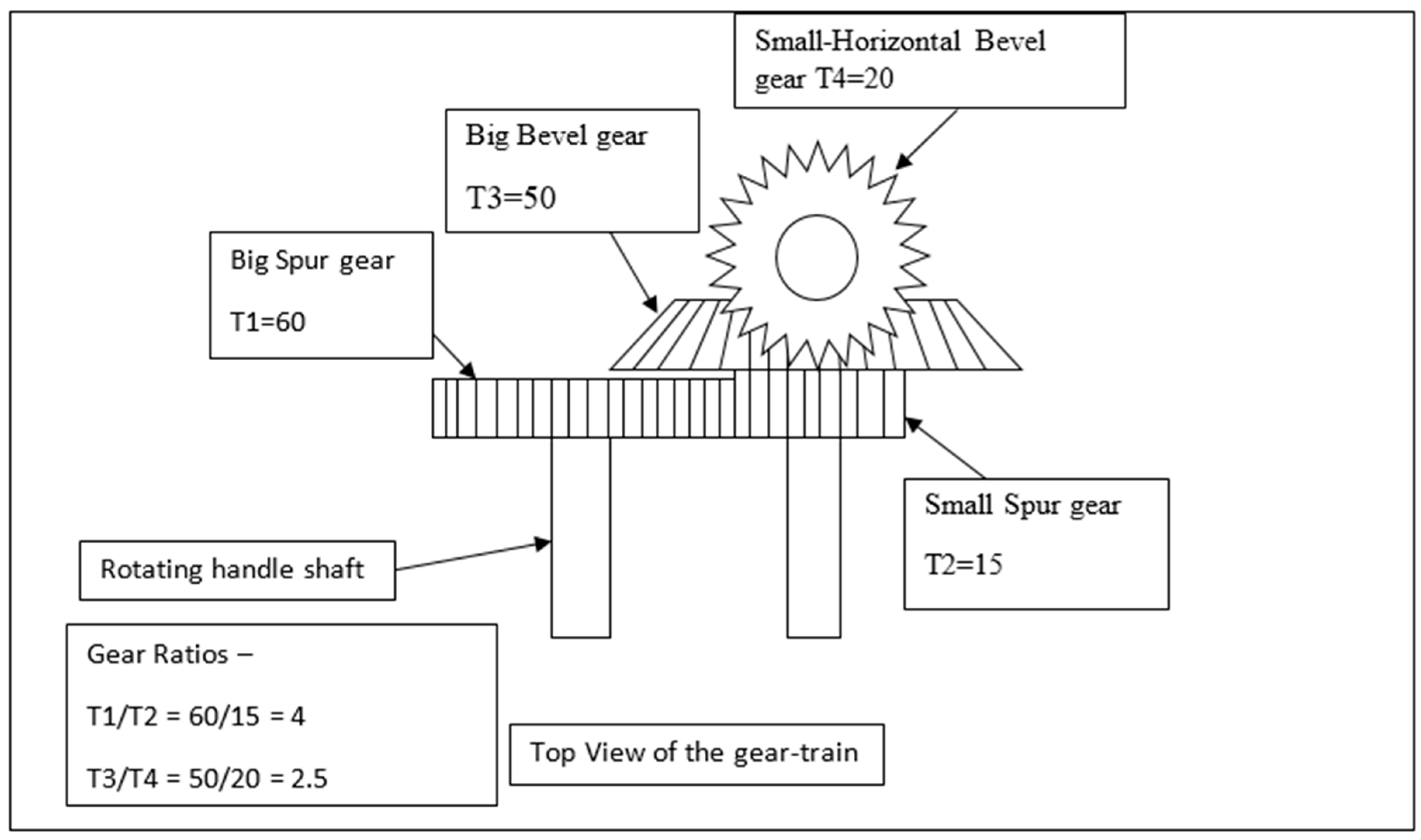
2.1.1. Gear Designing and Final Drive Calculations
- Teeth on 1st spur gear: T1 = 60;
- Teeth on 2nd spur gear: T2 = 15;
- Teeth on 1st bevel gear: T3 = 50;
- Teeth on 2nd bevel gear: T4 = 20.
2.1.2. Operation of Design
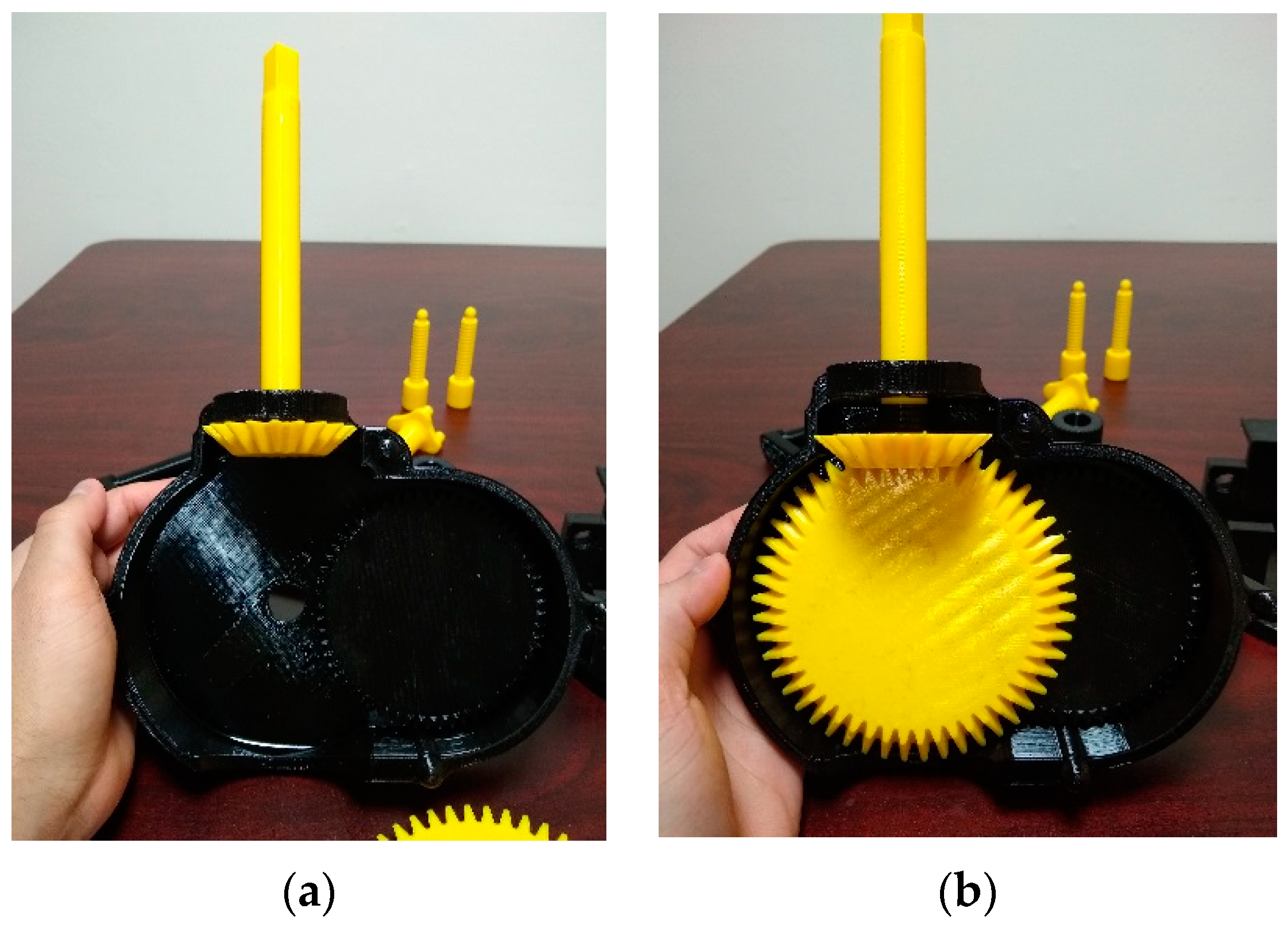
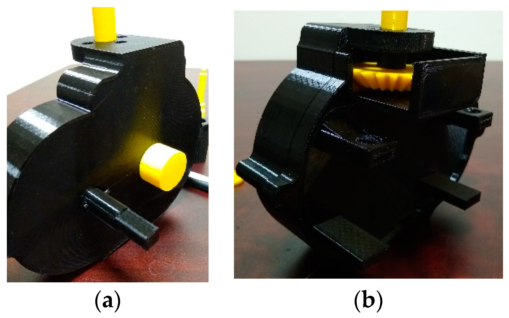
- Rotating the handle rotates the bigger spur gear, which starts the motion. The two spur gears in contact have equal modules. The module is the ratio of the reference diameter of the gear to the number of teeth on the gear. The bigger spur gear has 60 teeth and a module of 2. Although a larger spur gear would yield a higher gear ratio, it would also increase the size of the casing and in turn the size of the whole apparatus. A spur gear with 60 teeth and a module of 1.5 modules was chosen, considering the need of the final required rotations of the rotor (N4). Meshed to the bigger spur gear is a smaller spur gear with an equal module. To mesh and rotate a set of any gears, it is necessary that both the gears should have the same profile and an equivalent module. This smaller spur gear is coupled to a larger bevel gear to eliminate the overhang and also another component required to hold the two together. The bigger bevel gear has 50 teeth and a module of 2. The bevel gear is used to transmit the motion in a perpendicular direction. A smaller bevel gear is then meshed with the large one to increase the rotations per minute of the test tubes.
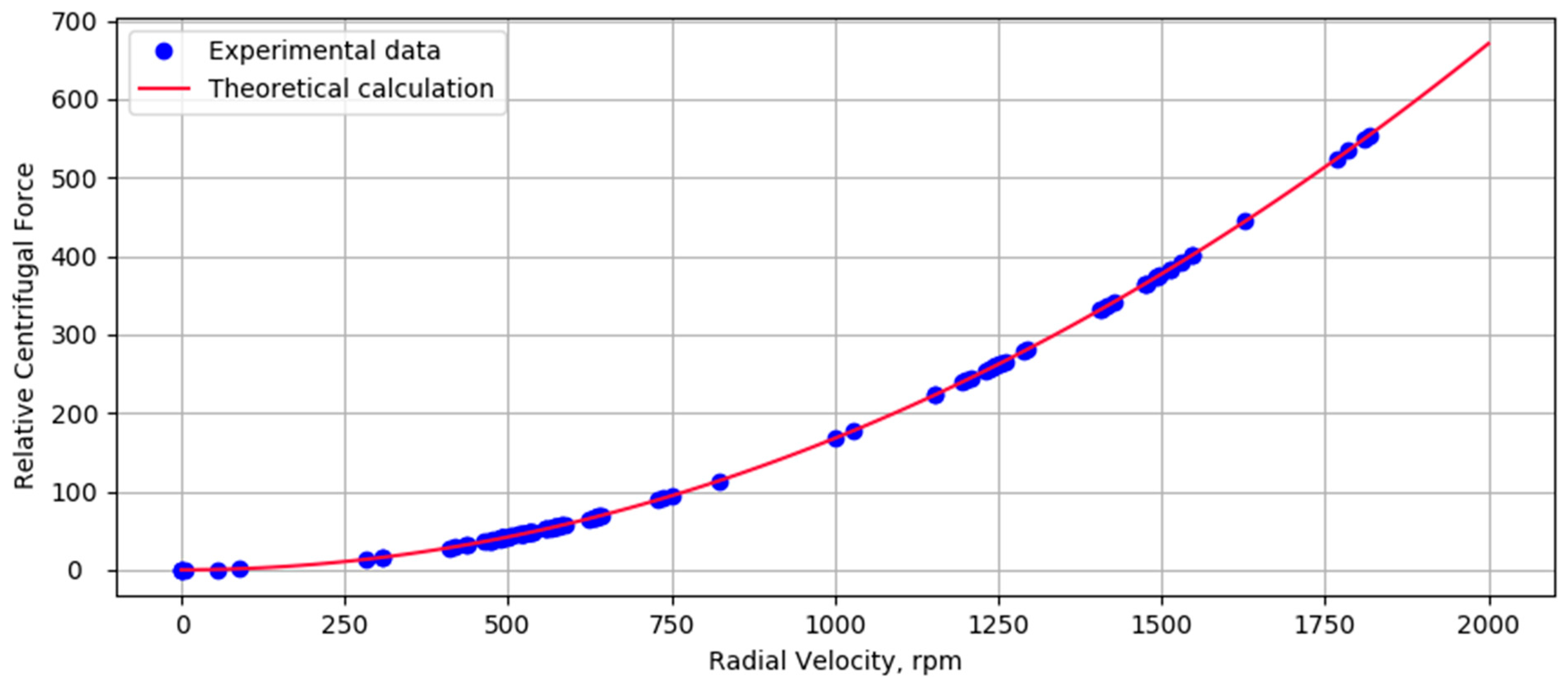
- High rotational speeds of 1200–2000 rpm are required to carry out typical medical tests. Thus, this gear train is designed in such a way that, with every two rotations per second, the rotor rotates at 1200 rpm. With every 2.5 rotations per second of the handle, the rotor rotates at 1500 rpm, and with 3 rotations per second, it can do 1800 rpm. The commercial equivalent products are capable of rotating at 1800 rpm, which is equal to the rotational capability of this 3-D printed centrifuge apparatus. The speeds can be easily increased if the number of teeth on either of the bevels or spurs or both bigger gears are increased and the source code in FreeCAD (computer-aided design 3-D modeling software, www.freecadweb.org) is made available for those that need this capability.
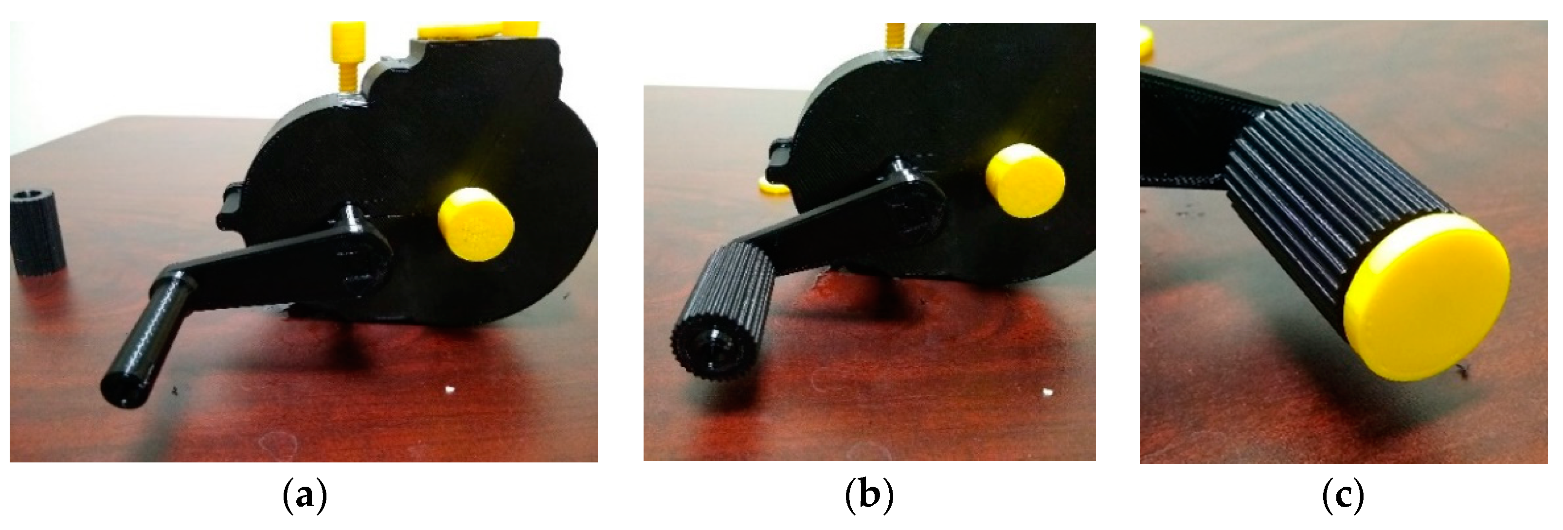
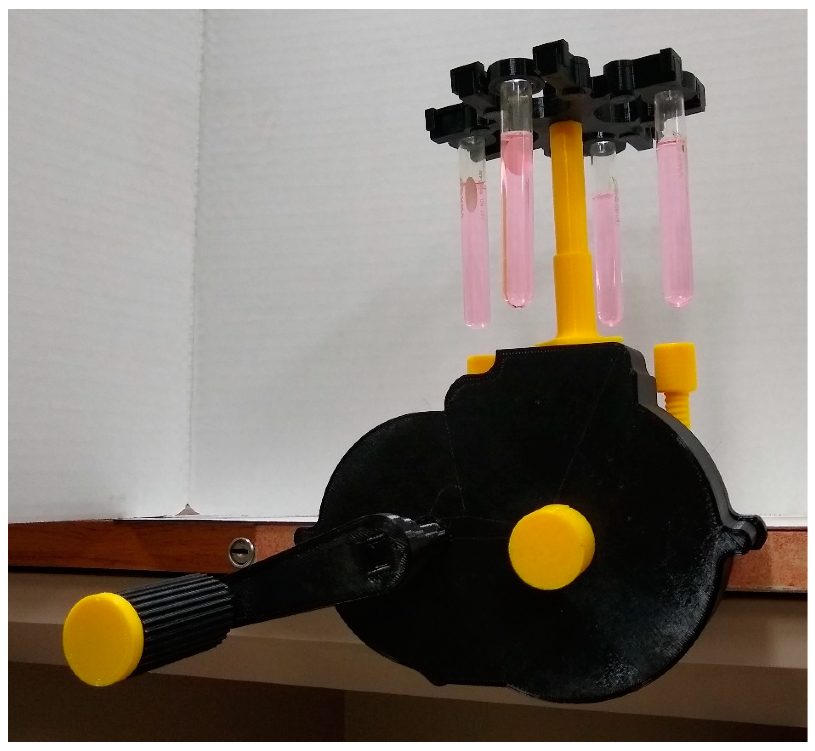
- The dimensions of the handle are designed in such a way that it will not interfere with the rotation of the test tubes. The grip is designed to keep in mind the ergonomics of the human hand and its motion while rotating the handle. Enough grip is provided on the grip bar, which freely rotates around the centerpiece of the handle. The horizontal motion of grip is constrained by implementing a ball–socket joint at the end of the handle.
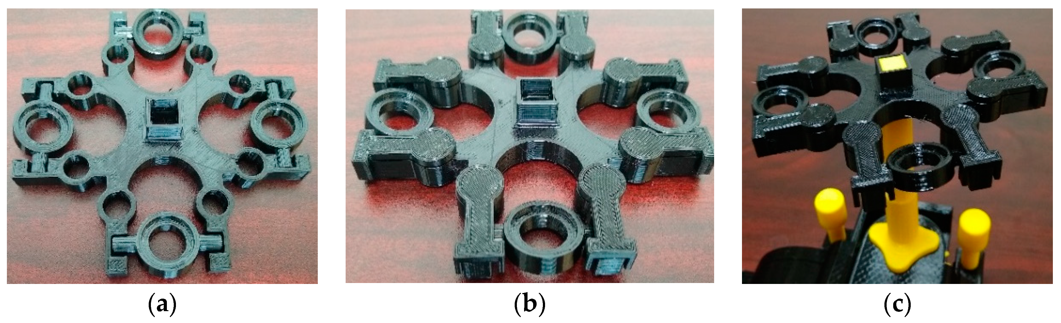
- Test tubes are placed in the test rings, which are specifically designed for standard test tubes. However, there is a wide variety of test tubes that are available on the market. All of the part files in FreeCAD are made available and open source so that others can adapt the tube holders to meet other sizes of test tubes. The test rings that hold the test tubes are locked in the rotor by using rotor snaps. These snaps can easily withstand the high centrifugal forces acting on them, as they are tightly fitted in the rotor itself. The rotor diameter is 120 mm, which is enough to generate high centrifugal force, following Equation (4).
2.1.3. Bill of Materials
2.2. Fabrication
2.3. Assembly
2.4. Operation
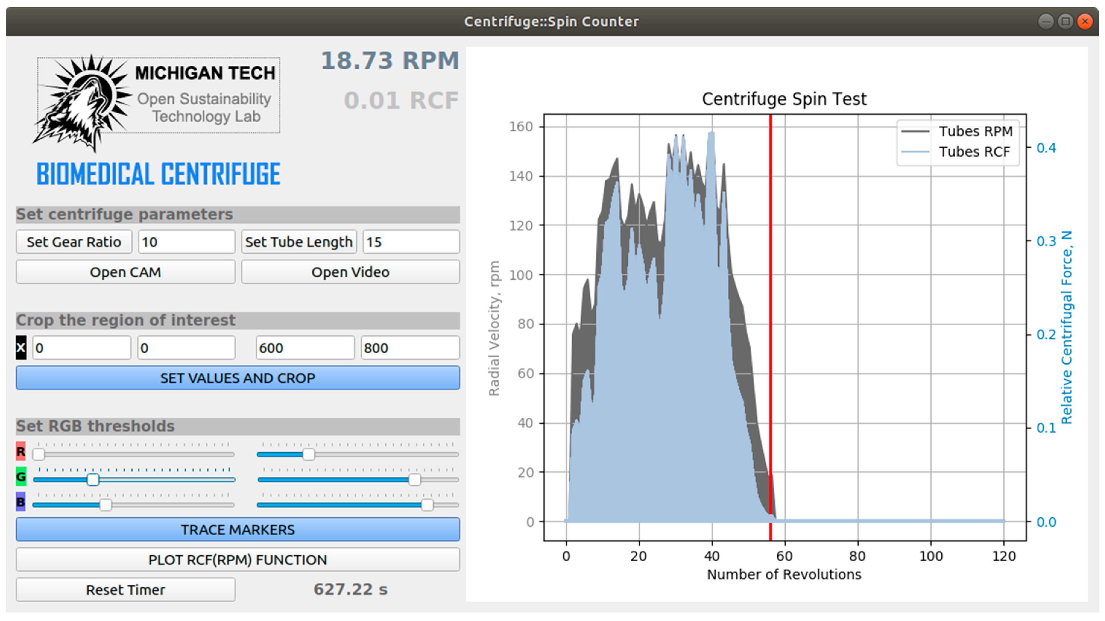
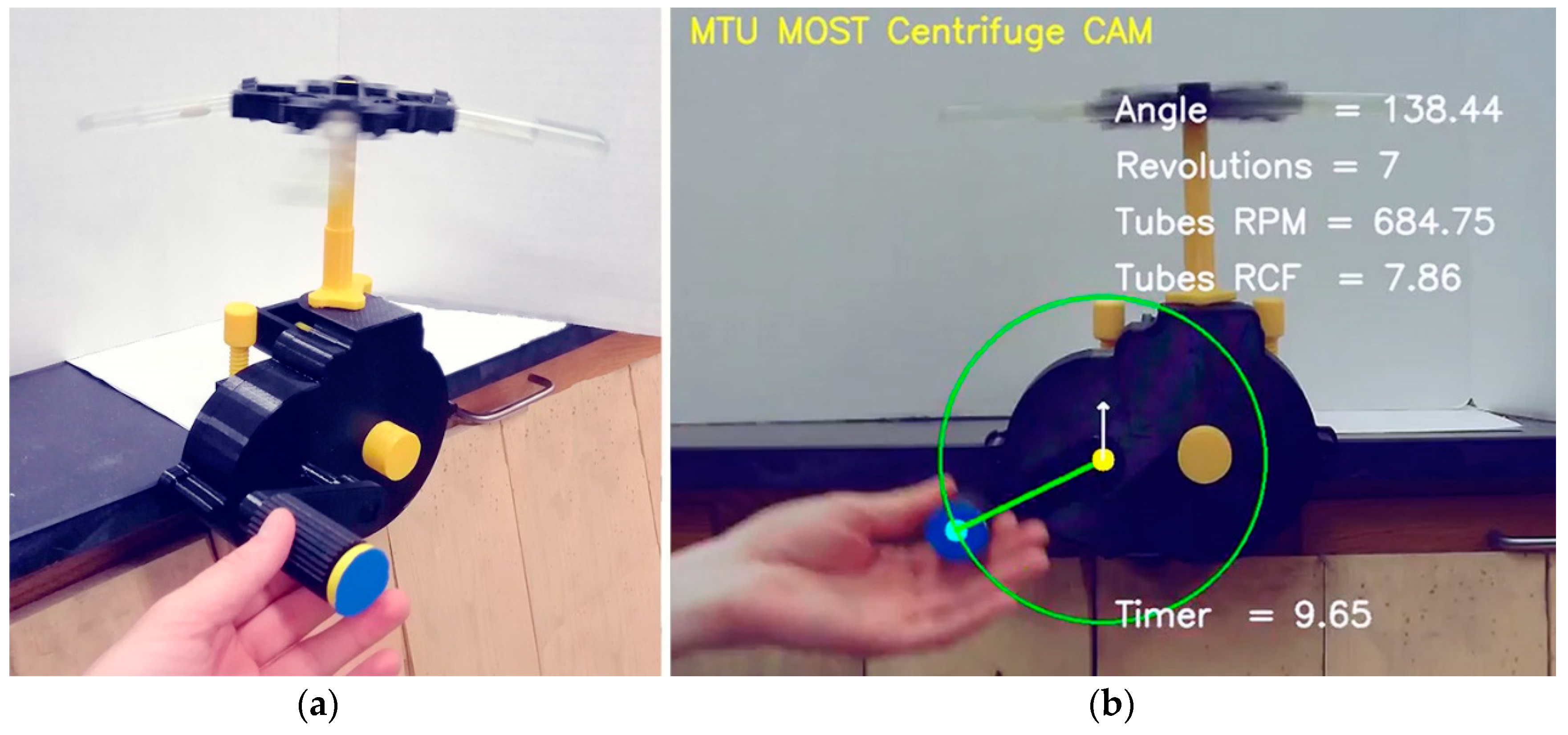
2.5. Validation
| Computing Angular Velocity and Relative Centrifugal Force |
| Input: an image frame from a camera or a video sequence. |
| Output: rpm and RCF values for the test tubes. |
| while a camera is open or a video is reading do: |
| get a single frame as an RGB image; |
| crop the region of interest of the image frame; |
| apply linear filtering to blur the cropped region; |
| mask the color marker using RGB thresholds; |
| apply operations of opening and closing to remove noise after RGB masking; |
| find the contours of the masked area. |
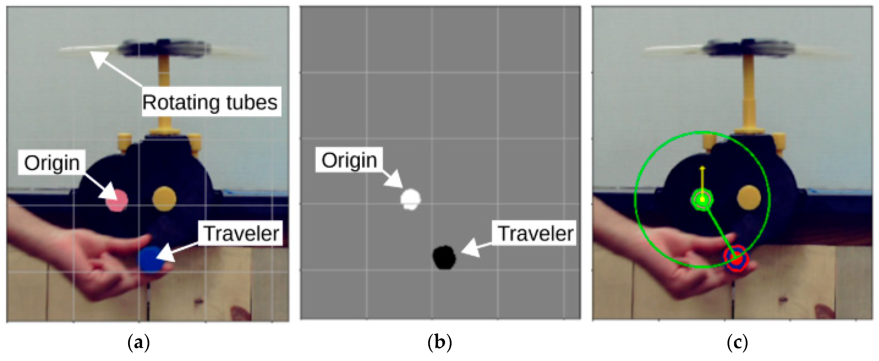
| if the traveler marker is detected do: |
| find the centroid location of the color marker applying the method of moments; |
| calculate the radius of rotation and the angle of the centrifuge arm. |
| if the angle is in a specified zero range do: |
| increase the number of revolutions by one; |
| update timer and compute the time period for one revolution; |
| calculate the tubes’ rpm; |
| calculate the tubes’ RCF. |
| end if |
| end if |
| end while |
2.6. Economic Analysis
3. Results
4. Discussion
5. Conclusions
Supplementary Materials
Author Contributions
Funding
Acknowledgments
Conflicts of Interest
References
- Gibb, A. Building Open Source Hardware: DIY Manufacturing for Hackers and Makers; Pearson Education: New York, NY, USA, 2014. [Google Scholar]
- Da Costa, E.T.; Mora, M.F.; Willis, P.A.; do Lago, C.L.; Jiao, H.; Garcia, C.D. Getting started with open-hardware: Development and control of microfluidic devices. Electrophoresis 2014, 35, 2370–2377. [Google Scholar] [CrossRef] [PubMed]
- Ackerman, J.R. Toward open source hardware. U. Dayton L. Rev. 2008, 34, 183–222. [Google Scholar]
- Powell, A. Democratizing production through open source knowledge: From open software to open hardware. Media Cult. Soc. 2012, 34, 691–708. [Google Scholar] [CrossRef]
- Von Hippel, E. Democratizing innovation: The evolving phenomenon of user innovation. JfB 2005, 55, 63–78. [Google Scholar] [CrossRef]
- Blikstein, P. Digital fabrication and “making” in education: The democratization of invention. FabLabs Mach. Mak. Invent. 2013, 4, 1–21. [Google Scholar]
- Gershenfeld, N. How to Make Almost Anything: The Digital Fabrication Revolution. Available online: http://cba.mit.edu/docs/papers/12.09.FA.pdf (accessed on 16 May 2019).
- Wittbrodt, B.; Laureto, J.; Tymrak, B.; Pearce, J. Distributed manufacturing with 3-d printing: A case study of recreational vehicle solar photovoltaic mounting systems. J. Frugal Innov. 2015, 1, 1–7. [Google Scholar] [CrossRef]
- Sells, E.; Bailard, S.; Smith, Z.; Bowyer, A.; Olliver, V. RepRap: The Replicating Rapid Prototyper-Maximizing Customizability by Breeding the Means of Production. In Proceedings of the World Conference on Mass Customization and Personalization, Cambridge, MA, USA, 7–10 October 2007. [Google Scholar]
- Jones, R.; Haufe, P.; Sells, E.; Iravani, P.; Olliver, V.; Palmer, C.; Bowyer, A. RepRap-the replicating rapid prototyper. Robotica 2011, 29, 177–191. [Google Scholar] [CrossRef]
- Bowyer, A. 3D Printing and humanity’s first imperfect replicator. 3D Print. Addit. Manuf. 2014, 1, 4–5. [Google Scholar] [CrossRef]
- Kietzmann, J.; Pitt, L.; Berthon, P. Disruptions, decisions, and destinations: Enter the age of 3-D printing and additive manufacturing. Bus. Horiz. 2015, 58, 209–215. [Google Scholar] [CrossRef]
- Lipson, H.; Kurman, M. Fabricated: The New World of 3D Printing; John Wiley & Sons: Indianapolis, IN, USA, 2013. [Google Scholar]
- Gwamuri, J.; Wittbrodt, B.; Anzalone, N.; Pearce, J. Reversing the trend of large scale and centralization in manufacturing: The case of distributed manufacturing of customizable 3-d-printable self-adjustable glasses. Chall. Sustain. 2014, 2, 30–40. [Google Scholar] [CrossRef]
- Attaran, M. The rise of 3-D printing: The advantages of additive manufacturing over traditional manufacturing. Bus. Horiz. 2017, 60, 677–688. [Google Scholar] [CrossRef]
- Tanikella, N.G.; Wittbrodt, B.; Pearce, J.M. Tensile strength of commercial polymer materials for fused filament fabrication 3D printing. Addit. Manuf. 2017, 15, 40–47. [Google Scholar] [CrossRef]
- Pearce, J.M. Building research equipment with free, open-source hardware. Science 2012, 337, 1303–1304. [Google Scholar] [CrossRef] [PubMed]
- Pearce, J. Open-Source Lab: How to Build Your Own Hardware and Reduce Research Costs; Elsevier: New York, NY, USA, 2013. [Google Scholar]
- Baden, T.; Chagas, A.M.; Gage, G.; Marzullo, T.; Prieto-Godino, L.L.; Euler, T. Open labware: 3-D printing your own lab equipment. PLoS Biol. 2015, 13, e1002086. [Google Scholar] [CrossRef] [PubMed]
- Coakley, M.; Hurt, D.E. 3D Printing in the laboratory: Maximize time and funds with customized and open-source labware. J. Lab. Autom. 2016, 21, 489–495. [Google Scholar] [CrossRef] [PubMed]
- Zhang, C.; Wijnen, B.; Pearce, J.M. Open-Source 3-D platform for low-cost scientific instrument ecosystem. J. Lab. Autom. 2016, 21, 517–525. [Google Scholar] [CrossRef] [PubMed]
- Dhankani, K.C.; Pearce, J.M. Open source laboratory sample rotator mixer and shaker. HardwareX 2017, 1, 1–12. [Google Scholar] [CrossRef]
- Trivedi, D.K.; Pearce, J.M. Open Source 3-D Printed Nutating Mixer. Appl. Sci. 2017, 7, 942. [Google Scholar] [CrossRef]
- Zhang, C.; Anzalone, N.C.; Faria, R.P.; Pearce, J.M. Open-Source 3D-Printable Optics Equipment. PLoS ONE 2013, 8, e59840. [Google Scholar] [CrossRef]
- Winters, B.J.; Shepler, D. 3D printable optomechanical cage system with enclosure. HardwareX 2018, 3, 62–81. [Google Scholar] [CrossRef]
- Agcayazi, T.; Foster, M.; Kausche, H.; Gordon, M.; Bozkurt, A. Multi-axis stress sensor characterization and testing platform. HardwareX 2019, 5, e00048. [Google Scholar] [CrossRef]
- Anzalone, G.C.; Glover, A.G.; Pearce, J.M. Open-Source Colorimeter. Sensors 2013, 13, 5338–5346. [Google Scholar] [CrossRef] [PubMed]
- Kelley, C.D.; Krolick, A.; Brunner, L.; Burklund, A.; Kahn, D.; Ball, W.P.; Weber-Shirk, M. An Affordable Open-Source Turbidimeter. Sensors 2014, 14, 7142–7155. [Google Scholar] [CrossRef] [PubMed]
- Wijnen, B.; Anzalone, G.C.; Pearce, J.M. Open-source mobile water quality testing platform. J. Water Sanit. Hyg. Dev. 2014, 4, 532–537. [Google Scholar] [CrossRef]
- Wittbrodt, B.T.; Squires, D.A.; Walbeck, J.; Campbell, E.; Campbell, W.H.; Pearce, J.M. Open-Source Photometric System for Enzymatic Nitrate Quantification. PLoS ONE 2015, 10, e0134989. [Google Scholar] [CrossRef]
- Wijnen, B.; Hunt, E.J.; Anzalone, G.C.; Pearce, J.M. Open-Source Syringe Pump Library. PLoS ONE 2014, 9, e107216. [Google Scholar] [CrossRef]
- Bravo-Martinez, J. Open source 3D-printed 1000 μL micropump. HardwareX 2018, 3, 110–116. [Google Scholar] [CrossRef]
- Pusch, K.; Hinton, T.J.; Feinberg, A.W. Large volume syringe pump extruder for desktop 3D printers. HardwareX 2018, 3, 49–61. [Google Scholar] [CrossRef]
- Garcia, V.E.; Liu, J.; DeRisi, J.L. Low-cost touchscreen driven programmable dual syringe pump for life science applications. HardwareX 2018, 4, e00027. [Google Scholar] [CrossRef]
- Pearce, J.M.; Anzalone, N.C.; Heldt, C.L. Open-Source Wax RepRap 3-D Printer for Rapid Prototyping Paper-Based Microfluidics. J. Lab. Autom. 2016, 21, 510–516. [Google Scholar] [CrossRef]
- Kong, D.S.; Thorsen, T.A.; Babb, J.; Wick, S.T.; Gam, J.J.; Weiss, R.; Carr, P.A. Open-source, community-driven microfluidics with Metafluidics. Nat. Biotechnol. 2017, 35, 523–529. [Google Scholar] [CrossRef] [PubMed]
- Niezen, G.; Eslambolchilar, P.; Thimbleby, H. Open-source hardware for medical devices. BMJ Innov. 2016, 2, 78–83. [Google Scholar] [CrossRef] [PubMed]
- Beeker, L.Y.; Pringle, A.M.; Pearce, J.M. Open-source parametric 3-D printed slot die system for thin film semiconductor processing. Addit. Manuf. 2018, 20, 90–100. [Google Scholar] [CrossRef]
- Pearce, J.M. Laboratory equipment: Cut costs with open-source hardware. Nature 2014, 505, 618. [Google Scholar] [CrossRef] [PubMed]
- Pearce, J.M. Impacts of Open Source Hardware in Science and Engineering. Bridge 2017, 47, 24–31. [Google Scholar]
- Hietanen, I.; Heikkinen, I.T.S.; Savin, H.; Pearce, J.M. Approaches to open source 3-D printable probe positioners and micromanipulators for probe stations. HardwareX 2018, 4, e00042. [Google Scholar] [CrossRef]
- Pearce, J. Quantifying the Value of Open Source Hardware Development. Mod. Econ. 2015, 6, 1–11. [Google Scholar] [CrossRef]
- Pearce, J.M. Return on investment for open source scientific hardware development. Sci. Public Policy 2016, 43, 192–195. [Google Scholar] [CrossRef]
- Dryden, M.D.M.; Fobel, R.; Fobel, C.; Wheeler, A.R. Upon the Shoulders of Giants: Open-Source Hardware and Software in Analytical Chemistry. Anal. Chem. 2017, 89, 4330–4338. [Google Scholar] [CrossRef]
- Cölfen, H.; Laue, T.M.; Wohlleben, W.; Schilling, K.; Karabudak, E.; Langhorst, B.W.; Brookes, E.; Dubbs, B.; Zollars, D.; Rocco, M.; et al. The Open AUC Project. Eur. Biophys. J. 2010, 39, 347–359. [Google Scholar] [CrossRef]
- CopabX, OpenFuge. Available online: https://www.instructables.com/id/OpenFuge/ (accessed on 28 March 2019).
- Polyfuge: A DIY Open-Source Microcentrifuge for Everyone. Available online: https://www.kickstarter.com/projects/1733191226/polyfuge-a-diy-open-source-microcentrifuge-for-eve (accessed on 28 March 2019).
- Warejoncas, Z.; Stewart, C.; Giannini, J. An Inexpensive, Open-Source Mini-Centrifuge. AMBT 2018, 80, 451–456. [Google Scholar] [CrossRef]
- Progress TH Follow 3D Printed DIYbio Mini-Centrifuge. Available online: https://www.instructables.com/id/3D-Printed-DIYbio-Mini-Centrifuge/ (accessed on 28 March 2019).
- Thingiverse. El-Cheapo Table Top Mini Fuge by Tiny Tim. Available online: https://www.thingiverse.com/thing:33818 (accessed on 28 March 2019).
- Garvey, C. Thingiverse.com DremelFuge—A One-Piece Centrifuge for Rotary Tools by Cathal Garvey. Available online: https://www.thingiverse.com/thing:1483 (accessed on 28 March 2019).
- Chagas, A.M. Haves and have nots must find a better way: The case for open scientific hardware. PLoS Biol. 2018, 16, e3000014. [Google Scholar]
- International Energy Agency. Energy Access Outlook. Available online: https://www.iea.org/access2017/ (accessed on 28 March 2019).
- Edomah, N. Governing sustainable industrial energy use: Energy transitions in Nigeria’s manufacturing sector. J. Clean. Prod. 2019, 210, 620–629. [Google Scholar] [CrossRef]
- Bhamla, M.S.; Benson, B.; Chai, C.; Katsikis, G.; Johri, A.; Prakash, M. Hand-powered ultralow-cost paper centrifuge. Nat. Biomed. Eng. 2017, 1, 0009. [Google Scholar] [CrossRef]
- Brown, J.; Theis, L.; Kerr, L.; Zakhidova, N.; O’Connor, K.; Uthman, M.; Oden, Z.M.; Richards-Kortum, R. A hand-powered, portable, low-cost centrifuge for diagnosing anemia in low-resource settings. Am. J. Trop. Med. Hyg. 2011, 85, 327–332. [Google Scholar] [CrossRef] [PubMed]
- Wong, A.P.; Gupta, M.; Shevkoplyas, S.S.; Whitesides, G.M. Egg beater as centrifuge: Isolating human blood plasma from whole blood in resource-poor settings. Lab. Chip. 2008, 8, 2032–2037. [Google Scholar] [CrossRef] [PubMed]
- Hand-Driven Centrifuge. Southern Labware. Available online: https://www.southernlabware.com/hand-driven-centrifuge.html (accessed on 28 March 2019).
- Hand-Driven Centrifuge. Carolina.com. Available online: https://www.carolina.com/catalog/detail.jsp?prodId=701816&s_cid=ppc_gl_products&utm_source=google&utm_medium=cpc&scid=scplp701816&sc_intid=701816&gclid=EAIaIQobChMIgIyF37yl4QIVwrfACh22aAlgEAQYAiABEgLe4PD_BwE (accessed on 28 March 2019).
- Mabey, D.; Peeling, R.W.; Ustianowski, A.; Perkins, M.D. Tropical infectious diseases: Diagnostics for the developing world. Nat. Rev. Microbiol. 2004, 2, 231–240. [Google Scholar] [CrossRef]
- Urdea, M.; Penny, L.A.; Olmsted, S.S.; Giovanni, M.Y.; Kaspar, P.; Shepherd, A.; Wilson, P.; Dahl, C.A.; Buchsbaum, S.; Moeller, G.; et al. Requirements for high impact diagnostics in the developing world. Nature 2006, 444, 73–79. [Google Scholar] [CrossRef]
- Dineva, M.A.; Mahilum-Tapay, L.; Lee, H. Sample preparation: A challenge in the development of point-of-care nucleic acid-based assays for resource-limited settings. Analyst 2007, 132, 1193–1199. [Google Scholar] [CrossRef]
- Mariella, R. Sample preparation: The weak link in microfluidics-based biodetection. Biomed. Microdev. 2008, 10, 777. [Google Scholar] [CrossRef]
- OSF. Available online: https://osf.io/besmf/ (accessed on 16 April 2019).
- GNU General Public License Version 3. Available online: https://www.gnu.org/licenses/gpl-3.0.en.html (accessed on 29 March 2019).
- Joe, J. Fully Printable C-Clamp Licensed Under Creative Commons—Attribution License. Available online: https://www.thingiverse.com/thing:1673030 (accessed on 29 March 2019).
- Cura LulzBot Edition. Available online: https://www.lulzbot.com/cura (accessed on 2 April 2019).
- OpenCV (Open Source Computer Vision Library). Available online: https://opencv.org/ (accessed on 16 April 2019).
- PyQt. Available online: https://wiki.python.org/moin/PyQt (accessed on 16 April 2019).
- MOST_Centrifuge_GUI. Available online: https://github.com/apetsiuk/MOST_Centrifuge_GUI (accessed on 16 April 2019).
- EIA. Electric Power Monthly. Available online: https://www.eia.gov/electricity/monthly/epm_table_grapher.php?t=epmt_5_6_a (accessed on 16 April 2019).
- PETg 3D Printer Filament. IC3D Filament. Available online: https://www.lulzbot.com/store/filament/ic3d-petg (accessed on 2 April 2019).
- Recyclebot. Appropedia. Available online: http://www.appropedia.org/Recyclebot (accessed on 2 April 2019).
- Baechler, C.; DeVuono, M.; Pearce, J.M. Distributed recycling of waste polymer into RepRap feedstock. Rapid Prototyp. J. 2013, 19, 118–125. [Google Scholar] [CrossRef]
- Woern, A.L.; McCaslin, J.R.; Pringle, A.M.; Pearce, J.M. RepRapable Recyclebot: Open source 3-D printable extruder for converting plastic to 3-D printing filament. HardwareX 2018, 4, e00026. [Google Scholar] [CrossRef]
- Cruz Sanchez, F.; Lanza, S.; Boudaoud, H.; Hoppe, S.; Camargo, M. Polymer recycling and additive manufacturing in an open source context: Optimization of processes and methods. In Proceedings of the 2015 Annual International Solid Freeform Fabrication Symposium-An Additive Manufacturing Conference, Austin, TX, USA, 12–14 August 2015; pp. 10–12. [Google Scholar]
- Cruz Sanchez, F.A.C.; Boudaoud, H.; Hoppe, S.; Camargo, M. Polymer recycling in an open-source additive manufacturing context: Mechanical issues. Addit. Manuf. 2017, 17, 87–105. [Google Scholar] [CrossRef]
- Zhong, S.; Rakhe, P.; Pearce, J.M. Energy Payback Time of a Solar Photovoltaic Powered Waste Plastic Recyclebot System. Recycling 2017, 2, 10. [Google Scholar] [CrossRef]
- Anderson, I. Mechanical properties of specimens 3d printed with virgin and recycled polylactic acid. 3D Print. Addit. Manuf. 2017, 4, 110–115. [Google Scholar] [CrossRef]
- Woern, A.L.; Pearce, J.M. 3-D Printable polymer pelletizer chopper for fused granular fabrication-based additive manufacturing. Inventions 2018, 3, 78. [Google Scholar] [CrossRef]
- Zander, N.E.; Gillan, M.; Lambeth, R.H. Recycled polyethylene terephthalate as a new FFF feedstock material. Addit. Manuf. 2018, 21, 174–182. [Google Scholar] [CrossRef]
- Pepi, M.; Zander, N.; Gillan, M. Towards Expeditionary Battlefield Manufacturing Using Recycled, Reclaimed, and Scrap Materials. JOM 2018, 70, 2359–2364. [Google Scholar] [CrossRef]
- Chong, S.; Pan, G.-T.; Khalid, M.; Yang, T.C.-K.; Hung, S.-T.; Huang, C.-M. Physical Characterization and Pre-assessment of Recycled High-Density Polyethylene as 3D Printing Material. J. Polym. Environ. 2017, 25, 136–145. [Google Scholar] [CrossRef]
- Kreiger, M.; Anzalone, G.C.; Mulder, M.L.; Glover, A.; Pearce, J.M. Distributed recycling of post-consumer plastic waste in rural areas. MRS Online Proc. 2013, 1492, 91–96. [Google Scholar] [CrossRef]
- Kreiger, M.A.; Mulder, M.L.; Glover, A.G.; Pearce, J.M. Life cycle analysis of distributed recycling of post-consumer high density polyethylene for 3-D printing filament. J. Clean. Prod. 2014, 70, 90–96. [Google Scholar] [CrossRef]
- Mohammed, M.I.; Mohan, M.; Das, A.; Johnson, M.D.; Badwal, P.S.; McLean, D.; Gibson, I. A low carbon footprint approach to the reconstitution of plastics into 3D-printer filament for enhanced waste reduction. KnE Eng. 2017, 2, 234–241. [Google Scholar] [CrossRef]
- Mohammed, M.I.; Wilson, D.; Gomez-Kervin, E.; Rosson, L.; Long, J. EcoPrinting: Investigation of Solar Powered Plastic Recycling and Additive Manufacturing for Enhanced Waste Management and Sustainable Manufacturing. In Proceedings of the 2018 IEEE Conference on Technologies for Sustainability (SusTech), Long Beach, CA, USA, 9–12 November 2018; pp. 1–6. [Google Scholar]
- Mohammed, M.I.; Das, A.; Gomez-Kervin, E.; Wilson, D.; Gibson, I. EcoPrinting: Investigating the use of 100% recycled Acrylonitrile Butadiene Styrene (ABS) for Additive Manufacturing. Solid Freeform Fabrication 2017. In Proceedings of the 28th Annual International Solid Freeform Fabrication Symposium, Austin, TX, USA, 7–9 August 2017. [Google Scholar]
- Mohammed, M.I.; Wilson, D.; Gomez-Kervin, E.; Vidler, C.; Rosson, L.; Long, J. The recycling of E-Waste ABS plastics by melt extrusion and 3D printing using solar powered devices as a transformative tool for humanitarian aid. In Proceedings of the 29th Annual International Solid Freeform Fabrication Symposium, Austin, TX, USA, 13–15 August 2018. [Google Scholar]
- Zhong, S.; Pearce, J.M. Tightening the loop on the circular economy: Coupled distributed recycling and manufacturing with recyclebot and RepRap 3-D printing. Resour. Conserv. Recycl. 2018, 128, 48–58. [Google Scholar] [CrossRef]
- Woern, A.L.; Pearce, J.M. Distributed Manufacturing of Flexible Products: Technical Feasibility and Economic Viability. Technologies 2017, 5, 71. [Google Scholar] [CrossRef]
- Zander, N.E.; Gillan, M.; Burckhard, Z.; Gardea, F. Recycled polypropylene blends as novel 3D printing materials. Addit. Manuf. 2019, 25, 122–130. [Google Scholar] [CrossRef]
- Pringle, A.M.; Rudnicki, M.; Pearce, J. Wood Furniture Waste-Based Recycled 3-D Printing Filament. For. Prod. J. 2018, 68, 86–95. [Google Scholar] [CrossRef]
- Tian, X.; Liu, T.; Wang, Q.; Dilmurat, A.; Li, D.; Ziegmann, G. Recycling and remanufacturing of 3D printed continuous carbon fiber reinforced PLA composites. J. Clean. Prod. 2017, 142, 1609–1618. [Google Scholar] [CrossRef]
- King, D.L.; Babasola, A.; Rozario, J.; Pearce, J.M. Mobile Open-Source Solar-Powered 3-D Printers for Distributed Manufacturing in Off-Grid Communities. Chall. Sustain. 2014, 2, 18–27. [Google Scholar] [CrossRef]
- Gwamuri, J.; Franco, D.; Khan, K.Y.; Gauchia, L.; Pearce, J.M. High-Efficiency Solar-Powered 3-D Printers for Sustainable Development. Machines 2016, 4, 3. [Google Scholar] [CrossRef]
- Khan, K.Y.; Gauchia, L.; Pearce, J.M. Self-sufficiency of 3-D printers: Utilizing stand-alone solar photovoltaic power systems. Renew. Wind Water Solar 2018, 5, 5. [Google Scholar] [CrossRef]
- Woern, A.L.; Byard, D.J.; Oakley, R.B.; Fiedler, M.J.; Snabes, S.L.; Pearce, J.M. Fused Particle Fabrication 3-D Printing: Recycled Materials’ Optimization and Mechanical Properties. Materials 2018, 11, 1413. [Google Scholar] [CrossRef] [PubMed]
- Byard, D.J.; Woern, A.L.; Oakley, R.B.; Fiedler, M.J.; Snabes, S.L.; Pearce, J.M. Green fab lab applications of large-area waste polymer-based additive manufacturing. Addit. Manuf. 2019, 27, 515–525. [Google Scholar] [CrossRef]
- Schelly, C.; Anzalone, G.; Wijnen, B.; Pearce, J.M. Open-source 3-D printing technologies for education: Bringing additive manufacturing to the classroom. J. Vis. Lang. Comput. 2015, 28, 226–237. [Google Scholar] [CrossRef]
- Bailey, M.; Grieco, J.; Speights, A.; Weiss, R.G. 3D printing in the classroom and laboratory. J. Comput. Sci. Coll. 2015, 31, 183–184. [Google Scholar]


| Component | Quantity | Description | Image of Component |
|---|---|---|---|
| Part A | 1 | Front plate |  |
| Part B | 1 | Back plate |  |
| Part C | 1 | Bigger spur gear with locking pin |  |
| Part D | 1 | Smaller spur gear with large bevel gear |  |
| Part E | 1 | Smaller bevel gear |  |
| Part F | 1 | Clamping ring for smaller bevel gear (Part E) |  |
| Part G | 1 | Rotor for test tubes |  |
| Part H | 1 | Clamping for Part D |  |
| Part I | 4 | Rings for test tube |  |
| Part J | 8 | Snaps for rotor |  |
| Part K | 2 | Bolts for clamping body |  |
| Part L | 2 | Base clips for the bolts |  |
| Part M | 1 | Smaller bevel gear holder |  |
| Part N | 1 | Handle |  |
| Part O | 1 | Grip for handle |  |
| Part P | 1 | Locking clip for handle |  |
| Part Name | Predefined Settings (Layer Height) | Infill (%) |
|---|---|---|
| A | High speed (0.38 mm) | 40 |
| B | High speed (0.38 mm) | 40 |
| C | Standard (0.28 mm) | 65 |
| D | Standard (0.28 mm) | 60 |
| E | Standard (0.28 mm) | 60 |
| F | High speed (0.38 mm) | 90 |
| G | High speed (0.38 mm) | 40 |
| H | High speed (0.38 mm) | 40 |
| I | Standard (0.28 mm) | 50 |
| J | Standard (0.28 mm) | 60 |
| K | Standard (0.28 mm) | 50 |
| L | High speed (0.38 mm) | 50 |
| M | High speed (0.38 mm) | 65 |
| N | High speed (0.38 mm) | 75 |
| O | High speed (0.38 mm) | 45 |
| P | High speed (0.38 mm) | 40 |
© 2019 by the authors. Licensee MDPI, Basel, Switzerland. This article is an open access article distributed under the terms and conditions of the Creative Commons Attribution (CC BY) license (http://creativecommons.org/licenses/by/4.0/).
Share and Cite
Sule, S.S.; Petsiuk, A.L.; Pearce, J.M. Open Source Completely 3-D Printable Centrifuge. Instruments 2019, 3, 30. https://doi.org/10.3390/instruments3020030
Sule SS, Petsiuk AL, Pearce JM. Open Source Completely 3-D Printable Centrifuge. Instruments. 2019; 3(2):30. https://doi.org/10.3390/instruments3020030
Chicago/Turabian StyleSule, Salil S., Aliaksei L. Petsiuk, and Joshua M. Pearce. 2019. "Open Source Completely 3-D Printable Centrifuge" Instruments 3, no. 2: 30. https://doi.org/10.3390/instruments3020030
APA StyleSule, S. S., Petsiuk, A. L., & Pearce, J. M. (2019). Open Source Completely 3-D Printable Centrifuge. Instruments, 3(2), 30. https://doi.org/10.3390/instruments3020030