From SPARC_LAB to EuPRAXIA@SPARC_LAB
by
 , , , ,
Riccardo Pompili
1,* ,
,
Enrica Chiadroni
1,
Alessandro Cianchi
2 ,
,
Massimo Ferrario
1,
Alessandro Gallo
1,
Vladimir Shpakov
1 and
Fabio Villa
1 1
Laboratori Nazionali di Frascati, Via Enrico Fermi 40, 00044 Frascati, Italy
2
Physics Department, University of Rome Tor Vergata and INFN, Via Ricerca Scientifica 1, 00133 Rome, Italy
*
Author to whom correspondence should be addressed.
Instruments 2019, 3(3), 45; https://doi.org/10.3390/instruments3030045
Submission received: 4 August 2019
/
Revised: 23 August 2019
/
Accepted: 26 August 2019
/
Published: 28 August 2019
(This article belongs to the Special Issue Physics and Applications of High Brightness Beams)
Abstract
:Following the promising results obtained at the SPARC_LAB test-facility in Frascati (Italy), we have recently submitted a proposal to develop a new facility driven by a plasma accelerator module for extended and user-oriented applications. The new multi-disciplinary user-facility will be equipped with a soft X-ray Free Electron Laser (FEL) operating with energies larger than 1 GeV. This design study is performed to be fully compatible with the EuPRAXIA design study. Here, the latest layout and beam parameters are presented.
1. Introduction
In the context of accelerator research, a fundamental milestone is represented by the realization of a new facility that will integrate high gradient accelerating modules based on plasma technology with a short wavelength Free Electron Laser (FEL) beamline. In this context, the Horizon 2020 design study EuPRAXIA [1] (European Plasma Research Accelerator with eXcellence In Applications) project aims at designing the world’s first accelerator facility based on advanced plasma-wakefield techniques to deliver 1–5 GeV electron beams that simultaneously have high charge, low emittance and low energy spread, which are required for applications by future user communities. In October 2019, the EuPRAXIA collaboration will conclude his work by proposing a solid strategy with the aim to demonstrate the possibility to use plasma accelerators for user applications. The EuPRAXIA design study will thus propose a set of beam parameters, produced for the first time by a plasma accelerator, able to generate short wavelength radiation in a FEL.
2. The EuPRAXIA@SPARC_LAB Project
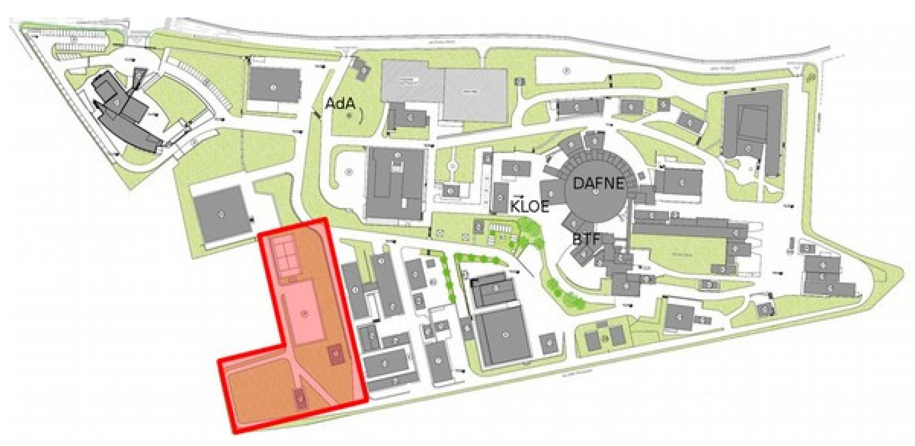
In the scenario envisioned by the EuPRAXIA design study, the EuPRAXIA@SPARC_LAB project [2] is intended to propose the LNF-INFN laboratories (Frascati, Italy) as possible host of the EuPRAXIA European Facility. The proposed facility will make available at LNF a unique combination made of: (i) a high-brightness electron beam with GeV energy generated in a novel X-band RF linac; (ii) a PW-class laser system; and (iii) a compact light-source directly driven by a plasma accelerator. These unique features will allow advanced researches oriented toward fundamental physics [3] with high social impact applications, especially in view of Key Enabling Technologies (KET) [4] and Smart Specialisation Strategies (S3) [5]. Starting from the SPARC_LAB experience [6], to achieve these goals and to meet the EuPRAXIA requirements, some activities are currently on-going at LNF. Firstly, we have to build a new infrastructure with the size of about m (see Figure 1), compatible to host the EuPRAXIA facility. Then, we have to design and develop the two pillars of the new facility: the first-ever 1 GeV X-band RF linac and an upgraded FLAME laser up to the PW range. Finally, we have to build and install downstream the linac and the plasma acceleration module a compact FEL source, equipped with user beam line at 3 nm wavelength.
From the previous considerations, the EuPRAXIA@SPARC_LAB proposal is thus conceived as an innovative tool that will allow multi-disciplinary investigations for scientific, technological and industrial purposes. The facility will be a high-brightness particle beams factory, able to produce not only electrons but also photons (from THz to -rays), neutrons, protons and positrons. The timeline developed so far foresees the start of the building construction within 2021 and the installation of all the components within 2024. In this year, the start of the commissioning phase is also expected.
3. Free Electron Laser Scientific Case
The advent of Free Electron Lasers (FELs) opened up the way for an unprecedented, wide class of experiments exploiting the peculiar features of these radiation sources [7]. Key elements are the high-peak brilliance and the short pulse duration, which is of the order of tens of femtoseconds. FELs can therefore allow high time resolution measurements and may provide a high signal-to-noise ratio. The choice of FEL configuration and radiation scheme for the EuPRAXIA@SPARC_LAB FEL is based on the user requests. In particular, the radiation wavelength, peak power, polarization and required average repetition rate. The time structure of the pulse has to be matched to the characteristic timescales of physical processes under study. For X-ray imaging and other high intensity applications, the photons should be delivered in ultra-short, high intensity pulses [8]. On the other hand, spectroscopic studies require limited peak intensity to avoid nonlinear processes, but also a high repetition rate in order to collect sufficient data in acceptable experimental periods. An interesting spectral region of operation is the so-called water window, i.e., the region between 2.5 nm and 4 nm. Users typically need about photons/pulse in a bandwidth at tunable wavelength within the water window at the experimental station. This radiation allows studying materials and biological tissues below the threshold of absorption of carbon. The machine we are proposing aims thus to provide FEL radiation in this range of wavelengths. Since no mirrors are available for confining radiation in a resonator at the wavelengths of interest, the Self-Amplified Spontaneous Emission configuration (SASE) will be the most suitable for the purpose.
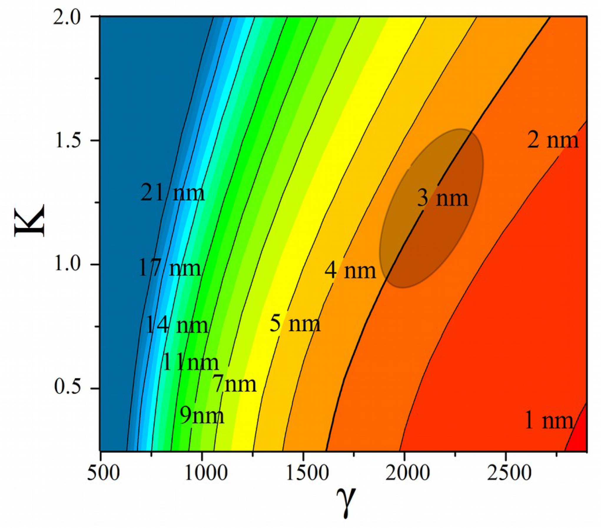
It is well known that for a single electron of given energy E, the resonance condition for the wavelength of the on-axis emitted radiation (in a planar undulator with magnetic field B) is
where is the undulator period, is the Lorentz factor and the undulator parameter. As shown in Figure 2, we have chosen as a target beam energy 1 GeV that allows FEL operation around 3 nm, which is an interesting wavelength for users aiming to applications in the biological domain. In addition, the resulting machine layout is fully compatible with the available room in the LNF laboratory with the state of the art undulator technology. Shorter wavelength will be also considered in the future, depending on further undulator technology development.
4. Plasma Acceleration
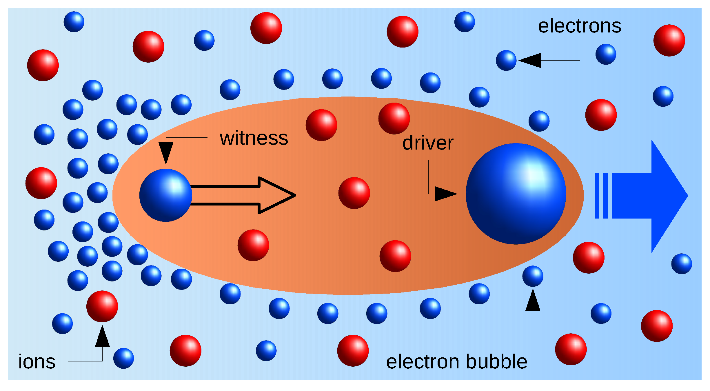
The concept of laser wakefield acceleration (LWFA) and plasma wakefield acceleration (PWFA) were first proposed in the late 1970s by Tajima and Dawson [9], holding the promise of producing high energy particle beams in length scales much smaller than what was then and is possible even today. Advancement in particle physics has historically been linked with the availability of particle beams of ever increasing energy or intensity. This revolutionary change permits one to avoid metallic or dielectric structure damage problems encountered in high-gradient operation. LWFA or PWFA may be adopted to excite space-charge oscillations in plasma. The working mechanism is shown in Figure 3. The resulting fields can be used for particle acceleration and focusing. Plasma accelerators have been built with active length ranging from the mm to the meter scale. The scaling law for the accelerating field as a function of the plasma density is
Thus far, accelerating gradients of several tens of GV/m have been successfully demonstrated in experiments [10,11] with improvements in accelerated beam quality that let us expect that advanced light sources (FEL, Compton, etc.) based on plasma-accelerators can be realized in the next decade. To proceed towards high-energy physics (HEP) applications, however, one must demonstrate progress in beam quality and control.
For the EuPRAXIA@SPARC_LAB facility, the plasma acceleration module will be used for both the PWFA [12] and LWFA [13] scenarios. To reach the required final energy (1–5 GeV), the length of the plasma channel will be adjusted accordingly. It will be around 1 m for the beam-driven case and of the order of 10 cm for the laser-driven one. The plasma will be produced in a capillary-discharge waveguide by ionizing H gas through the use of a high-voltage discharge current. To achieve the required accelerating gradients (1–10 GV/m), the plasma densities of interest will be in the cm range.
5. Beam Parameters
The strategy proposed for the EuPRAXIA@SPARC_LAB foresees the initial realization of a plasma-driven short wavelength FEL (according to the beam parameter reported in the Table 1) equipped with a beamline dedicated to users. The goal is to immediately provide useful FEL radiation in the water window region [14]. The expected performances show that the FEL, driven by a plasma accelerator in SASE configuration, is able to reach a peak brilliance which exceeds of about 10 orders of magnitude the one produced by conventional undulator sources. In addition, the pulse duration could be very short (of the order of fs-scale) with respect to what is currently attainable with storage ring based radiation source (ps-scale). We have investigated the possibility to fulfill the 1 GeV target energy of the EuPRAXIA scenario by using both plasma acceleration options (LWFA and PWFA) and also explored the possibility to drive the FEL with an higher bunch charge, 200 pC, in order to produce a larger number of photons. This is possible in a conventional configuration, i.e., exploiting the full X-band RF linac energy (1 GeV) without using the plasma module. All the details about the beam parameters are reported in Table 1.
6. Accelerator Layout
At EuPRAXIA@SPARC_LAB, the electron beam will be produced in an hybrid compact RF injector (S-band photo-injector followed by an X-band linac booster) coupled with a plasma accelerator module operating in the so-called external-injection configuration [15], i.e., the electrons accelerated are not internally catch from the plasma but come from an external and pre-accelerated witness bunch. From the RF injector point of view, the main challenges come from the request to provide ultra-short (<10 fs) and high quality (low energy spread and emittance) electron beams. For such a purpose, the bunches will be produced and pre-accelerated by a SPARC-like S-band photo-injector up to 100–170 MeV. This will then be coupled to an X-band linac booster (see Figure 4). The choice of such a configuration has been mainly guided by the expertise acquired at SPARC_LAB, where we achieved a stable and reproducible generation and manipulation of high-brightness electron beams as required by plasma-based experiments and generation of advanced radiation sources.
The EuPRAXIA@SPARC_LAB accelerator will be approximately 50 m long. The electron beams are generated in a 12 m long high-brightness photo-injector which will resemble the SPARC layout. It consists of a 1.6 cell S-band RF gun with a Copper photo-cathode mounted and driven by a short UV laser. A solenoid will be used for the emittance compensation process [16]. Three TW S-band accelerating sections follow the gun for a final energy ranging between 100–170 MeV, depending on the applied RF compression factor. Downstream the S-band injector, the X-band RF linac will bring the electron energy up to 0.5–1 GeV. Then, after it, a plasma acceleration structure is foreseen before the final undulator transfer line to imprint the final boost (1–2 GeV) to the beam. A 10 m-long magnetic chicane is inserted in the middle of the X-band Linac (between the L1 and L2 sections) for phase-space manipulation to achieve the longitudinal compression of the electron beam in order to reach peak currents of 2–3 kA.
6.1. The X-Band Linac
To provide the minimum 1 GeV energy required by the FEL, we foresee two options. The first one will use of a single stage of plasma acceleration, few tens of centimeters long, coupled with the RF Linac operating at 500 MeV. The second one will operate the Linac at twice the accelerating gradient in the X-band sections [17], without any use of the plasma acceleration module. The Eupraxia@SPARC_LAB X-band linac consists of two sections L1 and L2 (see Figure 4) located before and after the magnetic chicane respectively. L1 (L2) will consist of two (three) modules made of four structures, each one 90 cm-long. Downstream L1 the final energy will be in the range 250–400 MeV while after L2 the energy increases up to 0.5–1 GeV. This layout will resemble the one currently adopted for the Compact-Light design study project [18]. By considering that the maximum accelerating gradient applied is 65 MV/m, with a total active length of 18 m, we expect to reach a maximum achievable energy of 1.2 GeV by using only the RF linac. Downstream the L2 linac a 10 m long matching section is required to inject and match the electron beams into the plasma and to capture the accelerated one at the capillary exit. The last part of this section will transport the beam up to the undulator entrance. A four dipole magnetic chicane, 10 m long, will be used for phase space manipulation and longitudinal compression. The main parameters of the X-band linac are reported in Table 2.
6.2. Timing and Synchronization
The plasma acceleration process requires stable beams with ultra-low timing jitters [19]. This is mainly due to the fact that the accelerating region within the plasma is very small, of the order of 30–300 µm when considering typical plasma densities of cm. This corresponds to an oscillation period of 0.1–1 ps. The temporal jitter of the witness bunch must be therefore very small. For the EuPRAXIA@SPARC_LAB facility, we foresee the use of an ultra-stable reference signal generated in a central timing station to be distributed to the various clients through actively stabilized links. Each individual client (e.g., laser systems, RF power stations, and beam diagnostics hardware) has to be locked to the local reference provided by the timing distribution systems. Regarding the three different scenarios highlighted in Table 1, the laser-driven one is the most demanding since it operates at larger plasma densities. Being in this case the plasma oscillation period of the order of 100–200 fs, the maximum allowed timing jitter (according to numerical simulations) should be of the order of 20 fs [20]. To achieve this goal, the synchronization system will implement state-of-the-art solutions to guarantee a temporal coherence between all the outputs with a precision as low as 10 fs.
7. Conclusions
With the aim to candidate the LNF laboratories as a possible host site for the EuPRAXIA facility, we have proposed the realization of the EuPRAXIA@SPARC_LAB infrastructure. It will be a national multi-purpose facility, able to realize the scientific applications discussed in the previous sections. Being fully compatible with the EuPRAXIA requests, this project will represent a further step forward the real implementation of a plasma acceleration module for user-oriented applications.
Author Contributions
Writing–Original Draft, R.P.; Writing–Review and Editing, E.C., A.C., M.F., A.G., V.S. and F.V.
Funding
This work was supported by the European Union’s Horizon 2020 research and innovation program under grant agreement No. 653782.
Conflicts of Interest
The authors declare no conflict of interest.
References
- Walker, P.A.; Alesini, P.; Alexandrova, A.; Anania, M.P.; Andreev, N.; Andriyash, I.; Aschikhin, A.; Assmann, R.; Audet, T.; Bacci, A.; et al. Horizon 2020 EuPRAXIA design study. J. Phys. Conf. Ser. 2017, 874, 012029. [Google Scholar] [CrossRef]
- Ferrario, M.; Alesini, D.; Anania, M.; Artioli, M.; Bacci, A.; Bartocci, S.; Bedogni, R.; Bellaveglia, M.; Biagioni, A.; Bisesto, F.; et al. EuPRAXIA@ SPARC_LAB Design study towards a compact FEL facility at LNF. Nucl. Instrum. Methods Phys. Res. Sect. A 2018, 909, 134–138. [Google Scholar] [CrossRef]
- Balerna, A.; Bartocci, S.; Batignani, G.; Cianchi, A.; Chiadroni, E.; Coreno, M.; Cricenti, A.; Dabagov, S.; Di Cicco, A.; Faiferri, M.; et al. The Potential of EuPRAXIA@ SPARC_LAB for Radiation Based Techniques. Condens. Matter 2019, 4, 30. [Google Scholar] [CrossRef]
- Aschhoff, B.; Crass, D.; Cremers, K.; Grimpe, C.; Rammer, C.; Brandes, F.; Diaz-Lopez, F.; Woolthuis, R.K.; Mayer, M.; Montalvo, C. European Competitiveness in Key Enabling Technologies; Background Report to the EU Competitiveness Report; Centre for European Economic Research (ZEW): Mannheim, Germany, 2010. [Google Scholar]
- Evangelista, R.; Meliciani, V.; Vezzani, A. Specialisation in key enabling technologies and regional growth in Europe. Econ. Innov. New Technol. 2018, 27, 273–289. [Google Scholar] [CrossRef]
- Ferrario, M.; Alesini, D.; Anania, M.; Bacci, A.; Bellaveglia, M.; Bogdanov, O.; Boni, R.; Castellano, M.; Chiadroni, E.; Cianchi, A.; et al. SPARC_LAB present and future. Nucl. Instrum. Methods B 2013, 309, 183–188. [Google Scholar] [CrossRef] [Green Version]
- Chapman, H.N.; Barty, A.; Bogan, M.J.; Boutet, S.; Frank, M.; Hau-Riege, S.P.; Marchesini, S.; Woods, B.W.; Bajt, S.; Benner, W.H.; et al. Femtosecond diffractive imaging with a soft-X-ray free-electron laser. Nat. Phys. 2006, 2, 839–843. [Google Scholar] [CrossRef] [Green Version]
- Ackermann, W.; Asova, G.; Ayvazyan, V.; Azima, A.; Baboi, J.; Balandin, V.; Beutner, B.; Brandt, A.; Bolzmann, A.; Brinkmann, R.; et al. Operation of a free-electron laser from the extreme ultraviolet to the water window. Nat. Photonics 2007, 1, 336–342. [Google Scholar] [CrossRef]
- Tajima, T.; Dawson, J.M. Laser electron accelerator. Phys. Rev. Lett. 1979, 43, 267. [Google Scholar] [CrossRef]
- Litos, M.; Adli, E.; An, W.; Clarke, C.; Clayton, C.; Corde, S.; Delahaye, J.; England, R.; Fisher, A.; Frederico, J.; et al. High-efficiency acceleration of an electron beam in a plasma wakefield accelerator. Nature 2014, 515, 92–95. [Google Scholar] [CrossRef] [PubMed]
- Leemans, W.P.; Nagler, B.; Gonsalves, A.J.; Tóth, C.; Nakamura, K.; Geddes, C.G.R.; Esarey, E.; Schroeder, C.B.; Hooker, S.M. GeV electron beams from a centimetre-scale accelerator. Nat. Phys. 2006, 2, 696–699. [Google Scholar] [CrossRef]
- Chiadroni, E.; Alesini, D.; Anania, M.; Bacci, A.; Bellaveglia, M.; Biagioni, A.; Bisesto, F.; Cardelli, F.; Castorina, G.; Cianchi, A.; et al. Beam manipulation for resonant plasma wakefield acceleration. Nucl. Instrum. Methods Phys. Res. Sect. A 2017, 865, 139–143. [Google Scholar] [CrossRef] [Green Version]
- Rossi, A.; Petrillo, V.; Bacci, A.; Chiadroni, E.; Cianchi, A.; Ferrario, M.; Giribono, A.; Marocchino, A.; Conti, M.R.; Serafini, L.; et al. Plasma boosted electron beams for driving Free Electron Lasers. Nucl. Instrum. Methods Phys. Res. Sect. A 2018, 909, 54–57. [Google Scholar] [CrossRef]
- Petrillo, V.; Bacci, A.; Chiadroni, E.; Dattoli, G.; Ferrario, M.; Giribono, A.; Marocchino, A.; Petralia, A.; Conti, M.R.; Rossi, A.; et al. Free Electron Laser in the water window with plasma driven electron beams. Nucl. Instrum. Methods Phys. Res. Sect. A 2018, 909, 303–308. [Google Scholar] [CrossRef]
- Giribono, A.; Bacci, A.; Chiadroni, E.; Cianchi, A.; Croia, M.; Ferrario, M.; Marocchino, A.; Petrillo, V.; Pompili, R.; Romeo, S.; et al. EuPRAXIA@ SPARC_LAB: The high-brightness RF photo-injector layout proposal. Nucl. Instrum. Methods Phys. Res. Sect. A 2018, 909, 282–285. [Google Scholar] [CrossRef]
- Ferrario, M.; Alesini, D.; Bacci, A.; Bellaveglia, M.; Boni, R.; Boscolo, M.; Castellano, M.; Chiadroni, E.; Cianchi, A.; Cultrera, L.; et al. Experimental demonstration of emittance compensation with velocity bunching. Phys. Rev. Lett. 2010, 104, 054801. [Google Scholar] [CrossRef] [PubMed]
- Vaccarezza, C.; Alesini, D.; Bacci, A.; Cianchi, A.; Chiadroni, E.; Croia, M.; Diomede, M.; Ferrario, M.; Gallo, A.; Giribono, A.; et al. EUPRAXIA@ SPARC_LAB: Beam dynamics studies for the X-band Linac. Nucl. Instrum. Methods Phys. Res. Sect. A 2018, 909, 314–317. [Google Scholar] [CrossRef]
- D’Auria, G.; Di Mitri, S.; Rochow, R.; Latina, A.; Liu, X.; Rossi, C.; Schulte, D.; Stapnes, S.; Wu, X.; Wuensch, W. CompactLight DESIGN STUDY; JACoW Publishing: Geneva, Switzerland, 2019. [Google Scholar]
- Pompili, R.; Anania, M.P.; Bellaveglia, M.; Biagioni, A.; Castorina, G.; Chiadroni, E.; Cianchi, A.; Croia, M.; Giovenale, D.D.; Ferrario, M.; et al. Femtosecond timing-jitter between photo-cathode laser and ultra-short electron bunches by means of hybrid compression. New J. Phys. 2016, 18, 083033. [Google Scholar] [CrossRef]
- Rossi, A.; Anania, M.; Bacci, A.; Belleveglia, M.; Bisesto, F.; Chiadroni, E.; Cianchi, A.; Curcio, A.; Gallo, A.; Di Giovenale, D.; et al. Stability study for matching in laser driven plasma acceleration. Nucl. Instrum. Methods Phys. Res. Sect. A 2016, 829, 67–72. [Google Scholar] [CrossRef]
Figure 1.
Location of the new facility within the LNF site.

Figure 2.
Radiation wavelength as function of electron Lorentz factor and undulator parameter K with an undulator period cm. A value of corresponds to an electron beam energy GeV. The marked area is related to the possible operative parameter region.
Figure 2.
Radiation wavelength as function of electron Lorentz factor and undulator parameter K with an undulator period cm. A value of corresponds to an electron beam energy GeV. The marked area is related to the possible operative parameter region.

Figure 3.
In a plasma wakefield accelerator, a drive pulse, which can be either a laser pulse (LWFA) or an electron beam (PWFA), pushes away all the plasma electrons in an ionized gas, or plasma, leaving behind a region of positive charge. In such an ion bubble, an accelerating electric field is produced. It can be used to accelerate a witness bunch injected behind the driver pulse.

Figure 4.
Final layout of the accelerator facility.


Table 1.
Beam parameters for plasma and conventional RF linac driven FEL.
| Parameter | Units | 1 GeV PWFA | 1 GeV LWFA | 1 GeV X-Band |
|---|---|---|---|---|
| Charge | pC | 29 | 26.5 | 200 |
| Duration (rms) | fs | 11.5 | 8.4 | 55.6 |
| Peak current | kA | 2.6 | 3.15 | 1.79 |
| Repetition rate | Hz | 10 | 10 | 10 |
| Energy Spread (rms) | % | 0.73 | 0.81 | 0.05 |
| Emittance | µm | 0.6 | 0.47 | 0.5 |
| Radiation wavelength | nm | 2.79 | 2.7 | 2.87 |
| 2 | 2 | 1.55 (1.38) | ||
| cm | 1.5 | 1.5 | 1.5 | |
| K | 0.987 | 1.13 | 0.987 | |
| Undulator length | m | 30 | 30 | 16∼30 |
| Saturation power | GW | 0.85∼1.2 | 1.3 | 0.12∼0.33 |
| Energy | µJ | 63 | 63.5 | 64∼177 |
| Photons/pulse | 8.8 | 8.6 | 9.3∼25.5 | |
| Bandwidth | % | 0.35 | 0.42 | 0.24∼0.46 |
Table 2.
X-band linac main parameters.
| Parameter | Units | Value |
|---|---|---|
| Frequency | GHz | 11.9942 |
| Structure length | m | 0.9 |
| RF pulse duration | µs | 1.5 |
| Shunt impedance | M/m | 389 |
| Filling Time | ns | 130 |
| Input power | MW | 9.8 |
| Average gradient | MV/m | 65 |
| Linac active length | m | 18 |
© 2019 by the authors. Licensee MDPI, Basel, Switzerland. This article is an open access article distributed under the terms and conditions of the Creative Commons Attribution (CC BY) license (http://creativecommons.org/licenses/by/4.0/).
Share and Cite
MDPI and ACS Style
Pompili, R.; Chiadroni, E.; Cianchi, A.; Ferrario, M.; Gallo, A.; Shpakov, V.; Villa, F. From SPARC_LAB to EuPRAXIA@SPARC_LAB. Instruments 2019, 3, 45. https://doi.org/10.3390/instruments3030045
AMA Style
Pompili R, Chiadroni E, Cianchi A, Ferrario M, Gallo A, Shpakov V, Villa F. From SPARC_LAB to EuPRAXIA@SPARC_LAB. Instruments. 2019; 3(3):45. https://doi.org/10.3390/instruments3030045
Chicago/Turabian StylePompili, Riccardo, Enrica Chiadroni, Alessandro Cianchi, Massimo Ferrario, Alessandro Gallo, Vladimir Shpakov, and Fabio Villa. 2019. "From SPARC_LAB to EuPRAXIA@SPARC_LAB" Instruments 3, no. 3: 45. https://doi.org/10.3390/instruments3030045