Dipole Magnets above 20 Tesla: Research Needs for a Path via High-Temperature Superconducting REBCO Conductors


Lawrence Berkeley National Laboratory, Berkeley, CA 94720, USA
*
Author to whom correspondence should be addressed.
Instruments 2019, 3(4), 62; https://doi.org/10.3390/instruments3040062
Submission received: 9 September 2019
/
Revised: 1 November 2019
/
Accepted: 5 November 2019
/
Published: 22 November 2019
(This article belongs to the Special Issue Applied Superconductivity for Particle Accelerator)
Abstract
:To enable the physics research that continues to deepen our understanding of the Universe, future circular colliders will require a critical and unique instrument—magnets that can generate a dipole field of 20 T and above. However, today’s maturing magnet technology for low-temperature superconductors (Nb-Ti and Nb3Sn) can lead to a maximum dipole field of around 16 T. High-temperature superconductors such as REBCO can, in principle, generate higher dipole fields but significant challenges exist for both conductor and magnet technology. To address these challenges, several critical research needs, including direct needs on instrumentation and measurements, are identified to push for the maximum dipole fields a REBCO accelerator magnet can generate. We discuss the research needs by reviewing the current results and outlining the perspectives for future technology development, followed by a brief update on the status of the technology development at Lawrence Berkeley National Laboratory. We present a roadmap for the next decade to develop 20 T-class REBCO accelerator magnets as an enabling instrument for future energy-frontier accelerator complex.
1. Introduction
Higher magnetic field strengths enable a higher beam energy and the potential for particle physics discovery. For a circular collider, the beam energy scales with the radius of the collider ring and the field strength of dipole magnets that bend the beams along the collider [1]. Since the Tevtron, all major circular colliders are enabled by a special instrumentation—superconducting accelerator magnets [1,2]. Along its 26.7 km long circumference, the Large Hadron Collider (LHC) at CERN has 1232 superconducting arc dipole magnets made of Nb-Ti strands and each magnet can generate a nominal dipole field of 8.3 T at 1.9 K [2]. In 2012, CERN announced the discovery of Higgs boson based on the experiments at LHC.
To collide beams with higher energies, we need superconducting materials and associated magnet technology that can sustain higher magnetic fields [3,4]. Dipole magnets based on today’s Nb3Sn conductors can generate around 16 T, while research continues increasing the potential of Nb3Sn conductors towards a dipole field of 20 T at 4.2 K [5,6,7]. To generate dipole fields above 20 T, high-temperature superconductors (HTS) are required. Two main candidates are Bi-2212 round wires [8] and REBCO coated conductors [9]. Here we will focus on REBCO conductors.
Since the first demonstration of REBCO tape with high current density [10], the REBCO coated conductor technology has been progressed tremendously due to its potential in utility and power applications [11]. As of 2019, 15 companies in Asia, Europe, and North America offer commercial REBCO tape products. Although the anticipated utility applications have not yet been realized, high-field magnet applications have been rising as an important customer for the REBCO market [12,13,14]. An early and strong ongoing direction is the solenoid magnet applications based on single REBCO tapes that lead to a series of record dc magnetic fields with the most recent one reaching 45.5 T [15,16,17,18].
To highlight the opportunities and challenges of REBCO conductors, we compare the typical properties of Nb-Ti, Nb3Sn, Bi-2212 and REBCO in Table 1. These technical superconducting materials are currently commercially available and relevant for high-field superconducting accelerator magnet applications. The attempt here benefits from earlier comparisons [19,20,21,22,23,24,25,26]. The Nb-Ti conductor is represented by the one for the LHC main dipole [24]. For Nb3Sn, the conductor properties for the High Luminosity LHC low- quadrupole magnet is used [27]. The latest record performance for Bi-2212 round wire is from [28]. Three cable candidates are considered for REBCO, the Roebel cable [29], the CORC® wire [30] and the symmetric tape round (STAR) wire [31]. Other cable configurations such as twisted-stack [32] and exfoliated REBCO cable [33] may also be viable for accelerator magnet applications.
Table 1 highlights the unique capability of REBCO conductors to generate a high magnetic field over a broad temperature range. High mechanical strengths, no heat treatment, and possible round wire configurations are attractive for magnet development. On the other hand, the performance of round REBCO wires (the whole-conductor current density and total transport current capacity at a small bending radius) needs to improve. Indeed, there is significant potential to enable this improvement as evidenced by the record current density recently demonstrated in short REBCO tape samples [71]. This can also be seen in Figure 1 where we compare the current density across the whole conductor cross-sectional area. A comparison of the upper critical fields can be found in [8].
Several programs in the high-energy physics (HEP) community are developing REBCO magnets as a new technology paradigm [4]. The EuCARD series programs, an European collaboration lead by CERN, have been pioneering the development for REBCO accelerator magnets [73,74]. The collaboration successfully demonstrated a record bore field of 5.37 T in racetrack coils with a stack of two tapes at 4.2 K [75,76]. Focusing on the Roebel cables [22,77], the EuCARD2 program demonstrated the record dipole field of 3.1 T at 5.7 K with an aligned-block dipole magnet [78,79]. Designs of hybrid dipole magnets with HTS inserts [80] and stand-alone REBCO dipole magnets were also developed [67].
In Japan, the development of REBCO accelerator magnet technology focuses on conduction-cooled applications ranging from cancer therapy to accelerator-driven subcritical reactors in collaboration with industry [81]. An automated winding machine was developed to wind coils in complex 3D shapes using single tapes [81,82]. Detailed experimental and simulation studies have been performed to understand the current distribution and its impact on the spatial and temporal field quality critical for accelerator magnet applications [83,84,85,86].
In the U.S., the magnet technology development is shifting its foucs from single tapes [87,88,89] to multi-tape cables under the framework of the U.S. Magnet Development Program (USMDP). The USMDP, supported by the Office of High Energy Physics at the U.S. Department of Energy, has a dedicated component to develop HTS accelerator magnet technology with an initial goal to demonstrate a 5 T dipole field and to measure its field quality [90].
In this paper, we discuss the research needs to develop high-field dipole magnets as an enabling instrument for future energy-frontier accelerator complex. More specifically, we focus on a dipole field of 20 T and above using REBCO conductors. We present a series of driving questions that we believe are critical to achieve the goal of 20 T. The research required to address these driving questions covers the technology development on both REBCO magnets and conductors. We will discuss the direct and significant needs of the instrumentation and measurements for the technology development. The strong coupling and feedback between the magnet and conductor development are most effective to advance the performance of REBCO accelerator magnets. The synergies with the development needs for high-field fusion magnets and conductors are also highlighted. We also present a roadmap for the REBCO technology over the next decade towards the 20 T dipole field. Finally, we briefly summarize the status of REBCO magnet technology development at Lawrence Berkeley National Laboratory (LBNL).
2. Overarching Goal
Our goal is to generate a dipole field of 20 T and above using REBCO conductors. By developing and demonstrating the REBCO high-field magnet technology as an enabling instrument for high-energy physics and fusion applications, we hope to stimulate various applications and industrial competition to drive down the cost of REBCO conductors and magnets.
There are two approaches to reach a 20 T dipole field. The first is to use an LTS/HTS hybrid configuration. An HTS magnet is inserted into the aperture of an LTS magnet to boost the total dipole field in the magnet aperture, similar to the hybrid solenoid magnet configurations [16,91,92]. Designs of hybrid dipole magnets were proposed for high energy circular colliders [80,93]. The main issues are the technical complexity of the system and the ultimate field one can reach.
The second approach is to develop all-REBCO dipole magnets. This approach eliminates the interaction between the HTS and LTS magnets and can potentially avoid issues in terms of mechanics, magnetics and quench protection as the HTS and LTS conductors have significantly different critical surfaces and stability margins. With the high thermal stability margin, the REBCO magnets may avoid the training issue typically seen in the LTS magnets. The approach also enables the magnet operation above the liquid helium temperature. Conductor cost and availability is the main constraint for this approach.
Both approaches are enabled by the superior properties of REBCO conductors. The irreversibility field of a REBCO thin film is above 100 T with the field in parallel with the c-axis of the film between 4.2 and 20 K [36,94] (Table 1). The pinning force of laboratory REBCO tape samples has been demonstrated to be flat up to 30 T at 4.2 K so far [71,95].
The hybrid and all-REBCO approaches are not mutually exclusive. We consider the hybrid approach a critical first step for the development of an all-REBCO high-field magnet. It allows us to measure the mechanical resilience of HTS inserts under high Lorentz load and to provide early feedback to the development of REBCO conductor and magnet technology. Today’s high cost of REBCO conductors (Table 1) also favors the hybrid approach to achieve 20 T, although the cost can significantly reduce due to the low raw material cost, given enough production and yield volume [19,25,96].
3. Driving Questions and Research Needs to Reach 20 T Dipole Fields
We introduce a few questions that we believe are important to drive the technology development of REBCO accelerator magnets towards 20 T and above. Concerning both magnets and conductors, these questions are naturally intertwined. To effectively address them, the development of REBCO conductor and magnet technology should strongly collaborate and interact. The successful technology development will rely on advanced measurement and simulation techniques. Figure 2 summarizes the driving questions and their relationship.
The ceramic REBCO layer in a coated conductor is brittle. Therefore, the challenge for REBCO conductor and magnet technology is upfront: in addition to the pre-existing mechanical defects in the conductors, stress/strain experienced by the REBCO layer during cabling, magnet fabrication and operation, can degrade or damage the REBCO layer causing an irreversible reduction in its current-carrying capability. One of the fundamental issues for our quest to a dipole field of 20+ T is to measure and understand the mechanics of REBCO conductors and to minimize and mitigate the conductor degradation due to stress/strain.
We assume that high-field accelerator magnets require multi-tape REBCO cables or wires that will be simply called conductors here. High-current, on the order of 10–20 kA, multi-tape conductors can reduce the magnet inductance to enable fast charging/discharging and to reduce the voltage gradient along the coil during current ramping [22,24]. The multi-tape conductor architecture can also allow current sharing between tapes to accommodate local defects in REBCO tapes.
We focus on the issues critical for field generation to demonstrate the feasibility and capability of high-field REBCO accelerator magnets. Other important issues such as radiation hardness that can affect the magnet design and operation will be covered elsewhere.
3.1. How to Make High-Field Accelerator Magnets Using Multi-Tape REBCO Conductor?
By making and testing magnets, we can understand and address the limits to various aspects of magnet performances. Therefore, the first question addresses the design and fabrication of magnets. Although racetrack and cos θ-type magnets using single REBCO tapes have been demonstrated [88,97,98,99], developing magnets with multi-tape REBCO conductors is in its early stage.
The key issue is to minimize the strain-induced conductor degradation with the magnet design and during the magnet fabrication such as winding and impregnation. This is a unique challenge for REBCO: Nb-Ti is ductile; Nb3Sn and Bi-2212 are sufficiently ductile before heat treatment for winding and only require special care when they are fragile after heat treatments. The winding strain on the REBCO layer depends on the conductor architecture and magnet design. Conductors with a high aspect ratio such as the Roebel cable can minimize the strain in REBCO layers by following the constant-perimeter principle for magnet design and conductor bending [100,101,102,103,104]. From this aspect, round REBCO conductors are more flexible and can work with diverse magnet designs, although to understand the critical current degradation and reduce the strain development is still critical [30,105,106,107,108,109,110].
In addition, automated cabling and winding process, instruments and associated procedures with minimum, controlled and reproducible handling of REBCO conductors is an important issue to be addressed for the design and development of high-current conductors and high-field magnets [81,82].
Impregnation enables cables to distribute the stresses and to operate with high transverse pressure. For instance, the transverse pressure that a Roebel cable can withstand increases from below 40 MPa to at least 170 MPa after impregnation [37,111,112]. Meanwhile, epoxy in contact with REBCO tapes can substantially degrade the tape due to the low delamination stress in REBCO tapes (about 10 MPa) [113,114]. One approach to address this issue is to tailor the mechanical properties of the epoxy so as to mitigate the tape degradation as much as possible [112,115,116,117,118], although non-negligible degradation still occurs in some cases when the epoxy touches the REBCO tapes [37,111]. A most effective approach appears to be completely shielding REBCO tapes from epoxy [15,116,119]. For all these solutions, a concern is poor or non-exisitent electrcal contact between tapes, which prevents good current sharing inside a multi-tape conductor (Section 3.4). The ideal situation is a support medium that provides the requisite stress distribution while enabling current sharing between tapes. For instance, can we support conductors and individual tapes inside the conductor and allow current sharing through conductive epoxy [120,121] or solder [122,123,124]? Can we replace the insulation and epoxy and embed the tapes in a media whose electrical resistance decreases with increasing temperature [125]? Systematic measurements will be required to address these questions.
Joints between conductors need low electrical resistance to minimize the heat generation during magnet operation. Although HTS conductors and magnets can tolerate higher heat load and hence possibly higher joint resistances, a low joint resistance on the order of 1 nΩ at self field is still desirable to minimize the refrigeration load [126] for accelerator magnets operating at 10–20 kA current range. This low resistance has been routinely achieved in joints for Nb-Ti and Nb3Sn Rutherford cables [65] (Table 1) but the joint technology for multi-tape REBCO conductors remains to be demonstrated to achieve the same low joint resistance. Part of the challenge is to expose each individual tape to maximize the direct current transfer to the REBCO layer which strongly depends on the conductor architecture. A fin-block technology demonstrated 10–20 nΩ joint resistance at 10 K for Roebel cables [66]. Joints for CORC® conductors demonstrated 2–6 nΩ resistance at 4.5 K [68]. With the well defined tape-tape contact condition, several studies show that the interfacial resistance inside a REBCO tape (Cu/Ag, Ag/REBCO) contribute strongly to the joint resistance [64,126,127]. Collaboration with tape manufacturers is needed to achieve a low and consistent interfacial resistance with the industrial tape manufacturing process. In addition to the low resistance, uniform joint resistance for each tape in a multi-tape conductor is critical to allow uniform current distribution to maximize the current-carrying capability of the multi-tape conductor [128,129,130].
3.2. What Is the Maximum Field a REBCO Dipole Magnet Can Achieve?
As we start learning how to make REBCO magnets, a natural question is how high can we push the field. To address this question, let us consider the parameters that can limit the maximum field for a REBCO magnet. The irreversibility field and transport current of REBCO conductor are not likely the limiting factors to reach a 20 T dipole field at an operating temperature below 20 K (Table 1). Indeed designs of all-REBCO magnets have been proposed to generate a 100 T dc solenoid field [92] and a 20 T dipole field [67]. We believe the mechanical load on the REBCO conductor, in particular, the stress and strain along and transverse to the longitudinal axis of the conductor, will determine the maximum dipole field one can achieve with REBCO conductors, similar to the case for Nb3Sn conductors [131].
Recent measurements show that multi-tape REBCO conductors can withstand large transverse stress. For instance, a 15-strand impregnated Roebel cable for the CERN REBCO dipole magnet [132] shows no degradation in critical current at 4.2 K for up to 370–440 MPa [37]. This stress level is sufficient for a 20 T block REBCO dipole design [67]. Measurements on commercial CORC® wires, without impregnation, showed an estimated irreversible stress limit between 99 and 241 MPa at 76 K, defined at a 3% degradation criterion [60].
Two questions need to be addressed:
- How does the measured stress/strain limit on various conductor architectures translate to the maximum achievable dipole fields? Similarly, how does a specific field target translate into the required stress/strain limit on a REBCO conductor? Credible and comprehensive mechanical analyses are required to address both questions.
To improve the conductor stress/strain limit, one can optimize conductor architecture such as introducing a stronger core material for the round REBCO wires [60]. It may also be necessary to support individual tapes in the conductor through impregnation to better distribute the stresses as discussed in Section 3.1. Magnet designs can also be exploited to reduce the peak stresses on the conductors. For instance, by embedding conductors in the magnet mandrel, the canted magnet concept can intercept the accumulation of Lorentz stress on conductors [135]. The block design can separate the high-field and high-stress regions to provide more operation margin on the conductors [7].
3.3. What Is the Long-Term Performance of REBCO Magnets under Lorentz Loads?
Accelerator magnets cycle the fields between the injection and collision levels during the physics experiments. It is therefore important to have a stable magnet performance over a certain lifetime. However, one concern for REBCO magnets is that their current-carrying capability may degrade over time. This is because the cracks in the ceramic REBCO layers, for example pre-existing or introduced during conductor and magnet fabrication, can only become worse under Lorentz loads and further degrade the conductor and magnet performance during the operation.
The available measurement data, though limited in statistics, indeed show non-negligible degradation in high-current REBCO conductors after cycling the Lorentz load [133,134,136,137,138]. On the other hand, cycling tests on CORC® conductors in liquid nitrogen with external mechanical loads show that the current-carrying capability does not degrade over 105 cycles when the load is below the irreversible limit [56,60].
Although the exact mechanism for the observed degradation and its impact on the magnet long-term performance remain to be clarified [137,139], observations from recent REBCO pancake coils in high background fields provide relevant insights. First, Lorentz forces can cause deformation and stress concentration in tapes and joints that are not well supported and lead to degradation [140,141]. One solution is to fully impregnate the coil [141], consistent with the significantly improved resilience to the transverse pressure in impregnated Roebel cables [37,111,112]. On the other hand, solder-filled REBCO fusion conductors still show degradation [19,142].
Second, pre-existing cracks in the REBCO layer from the tape-slit process can induce further degradation under the large hoop tension due to Lorentz load [18,143]. For solenoid insert coils wound with single tapes, one may avoid this issue by properly orienting the slit edge with respect to the background solenoid fields [18]. For magnets based on multi-tape REBCO conductors featuring more complex conductor and magnetic field orientations, more fundamental solutions are needed to eliminate the crack formation during the tape fabrication process. One option is the laser cutting technique that yields less damage in the REBCO layer compared to the mechanical slitting process [144,145]. More measurements are required to prove the performance of alternative slitting processes.
An effective approach to understanding the long-term behavior of REBCO magnets is to measure the transport behavior of the conductors and coils under large and cycling Lorentz load relevant to the conditions of magnet operation as is done for fusion conductors [133,137,146]. The HTS/LTS hybrid approach (Section 2) not only motivates but also provides a natural test bed for this study.
The first three driving questions focus on achieving the maximum dipole field with REBCO conductors. Addressing these questions will allow us to exploit the maximum potential of REBCO conductors. Figure 3 summarizes the relationship between these questions.
3.4. How Do REBCO Accelerator Magnets Transit from Superconducting to Normal State and How Can the Transition Be Detected?
The energy stored in a superconducting coil converts into heat during the superconducting-to-normal transition (quench). The excessive heat can degrade or damage the conductor, which must be avoided through the understanding of the quench behavior and early detection of the quench.
One question is how the heating and temperature develop in a multi-tape REBCO conductor [147,148,149]. Would the current sharing between tapes in a multi-tape architecture reduce the peak temperature compared to a single tape [150,151]? The answer through both experimental and computational studies will be important to understand the quench behavior of conductors with different margins due to local defects (Section 3.3) and/or different magnetic fields, temperatures and strain states in a coil. It will also provide useful feedback on the conductor design.
The key parameters here are the electrical and thermal contact resistances between tapes that can affect the current sharing and quench dynamics [149,151]. With a contact resistivity ranging from 20 to 100 μΩ cm2 [152], the non-insulation REBCO solenoid magnet technology demonstrates the self-protection capability thanks to the current sharing between the tapes [153]. On the other hand, measurements on short (<1 m) tape-stacked and CORC® conductors indicate that the current sharing occurs through the terminal dominated by the joint resistance when the electrical contact resistance between the tapes is high [129,130]. Measurements on the quench behavior of conductors and magnets with different contact resistances will be useful to clarify the current sharing mechanism and the impact of contact resistances.
The maximum allowable temperature in a REBCO conductor will determine the strategies for quench detection and protection. This peak temperature can depend on the conductor architecture [151] and can be established experimentally [154,155,156,157]. Two options can limit the peak temperature during a quench [158,159]. First, reduce the current density in the normal metal (such as the Cu stabilizer electroplated around the REBCO tape) during a transition. For round REBCO conductors such as CORC® and STAR wires, it would be useful for the metal former to carry most of the current during the transition since it occupies 30%–90% of the conductor cross-sectional area (Table 1) [38,160].
Second, reduce the time span when the hot-spot temperature increases with a sensitive quench detection, a significant challenge for instrument and measurement. New quench detection techniques measuring the temperature rise in the normal zone are under investigation [161,162,163,164,165,166,167]. Compared to the voltage-based detection technique, these new optic and acoustic techniques are more immune to electromagnetic interference, attractive for fusion applications. More tests with magnets to prove the feasibility of these new techniques are required.
Higher normal zone propagation velocity can also benefit the quench detection. For instance, coating with a high thermal conductivity applied on single tapes can double the turn-to-turn propagation speed compared to the turn-to-turn insulation with Kapton tape [168]. Increasing the interface resistance between the REBCO and stabilizer increases the normal zone propagation velocity by several orders of magnitude to the order of 1 m s−1 [169]. Further measurements in longer tapes and multi-tape conductors would be useful to demonstrate the benefit for quench detection and the impact on joint resistance (Section 3.1).
3.5. What Is the Field Quality of REBCO Accelerator Magnets?
In addition to the main field strength, REBCO accelerator magnets must deliver high static and dynamic field quality to steer particle beams. Design of accelerator magnets generally aim for field errors less than a few units at a reference radius of one-third of the magnet aperture [103,170]. One unit corresponds to 100 ppm of the main field. Although we expect that the physics of field quality for the LTS accelerator magnets [171,172] apply to the REBCO counterparts, several open questions need to be addressed.
One issue is the dc magnetization effects (persistent-current effects) [171] and whether the tape striation is needed to reduce the effects [173]. Leveraging the micron-thick REBCO layer and field orientation, the aligned-block dipole magnet using Roebel cables shows a small persistent-current (the normal sextupole) of 10–15 units [79,174]. Larger persistent effects are expected for other accelerator magnet designs such as designs and other conductor configurations such as CORC® and STAR wires (Table 1). As an example, the peak magnetization normalized to the wire volume of a CORC® wire at 4.2 K [175] is a factor of five higher than that of a Nb3Sn Rutherford cable measured at 1.9 K [176]. Tape striation is effective to reduce the magnetization in REBCO tapes [86,173,177,178], although it may increase the conductor cost/performance ratio. Compensation from the magnet aspect is another effective approach that should be explored [67,179,180].
If a low electrical contact resistance is required (Section 3.4), would it lead to pronounced dynamic field errors that depend on the current ramp rates as observed in LTS magnets [181,182,183,184,185,186]? Measurements from recent Roebel and CORC® dipole magnets show no pronounced dynamic field errors [174,187]. More measurements on magnets and cables preferably with different will be useful to address the question [188,189].
What is the decay behavior of the field components at the current plateau? For LTS accelerator magnets, the decay at the injection level can be related to the flux creep of superconductors [171] and a resistive current diffusion in a cable [190,191,192]. REBCO magnets may present new behaviors as the relaxation of the magnetization in REBCO can deviate from the logarithmic-time behavior and can strongly depend on the operation temperature [193]. The various architectures of multi-tape REBCO conductors may also yield different current diffusion processes affecting the decay behavior. More measurements and simulation studies on both conductor [49] and magnet levels are required to understand and control the behavior.
3.6. What Is the Required Performance for REBCO Conductors to Achieve the Desired Magnet Performance?
As part of the iterative development process for REBCO technology, the sixth question aims at providing guidance and feedback to the conductor development based on the desired and measured magnet performance [22,194]. The main aspects for the desired conductor performance include:
- Flexible to make magnets and robust/resilient to cycling electromagnetic and thermal loadsUnderstanding how strain develops in REBCO layer during the cabling and magnet winding processes will be critical [32,104,106,108,109,110,195,196]. The design tools based on the understanding of the conductor mechanics will help guide the development of more flexible round REBCO conductors and the optimized REBCO tapes with thinner substrates and narrower widths [34,38,160]. It is also important to systematically measure the impact of electromagnetic loads on conductors and to understand and mitigate potential conductor degradation.
- High transport current and current densityAn ultimate target for round REBCO conductors is 10–20 kA current-carrying capability at 20 T and a bending radius of 10 mm (Section 4). The current can be carried by a single or multiple REBCO conductors. Understanding the impact of tensile/compressive strain on tapes with thicker REBCO layer [71] will clarify its potential for multi-tape conductors. The current density in the stabilizer will determine the time budget to detect the superconducting-to-normal transition in multi-tape conductors [158]. The metal former that occupies a significant portion of round REBCO conductors should be leveraged to reduce the current density during the transition.
- Enhancing current sharing between tapes and suppressing inter-tape coupling currentsWe need to clarify the role of electrical contact resistances on both current sharing and inter-tape coupling and determine an optimal range for . It is important to measure and understand how current sharing between tapes affects the heat generation in multi-tape conductors during the transition. Implementing a controlled and reproducible on REBCO tapes can be a challenge. One option is to start with a minimum and evaluate its impact on the coupling losses and dynamic field errors.
With several available designs of multi-tape REBCO conductors, the community needs to develop, test REBCO magnets to build statistics on the magnet performance and understand how it is linked to the conductor design and optimization. Would different conductor options lead to different magnet performances? If so, is there a preferred conductor design for high-field REBCO accelerator or fusion magnets? Given a conductor design, is there a preferred magnet design that can achieve the best magnet performances? To effectively address these questions, we need a fast-paced technology evolution with integrated design and development of REBCO conductors and magnets.
3.7. How to Determine the Performance of a Long Multi-Tape REBCO Conductor for More Predictable Magnet Performance?
The current-carrying capability of REBCO tapes can degrade locally during the fabrication of a multi-tape conductor. Therefore, it is important to measure the transport performance of the multi-tape conductor after fabrication. The knowledge can help improve conductor fabrication. Together with the field, strain and temperature distribution in a magnet, this knowledge can also help predict the locations where the superconducting-normal transition in a magnet is likely to occur. This can enable a precision monitoring of transition to avoid magnet quenches, assuming REBCO magnets do not train.
Accelerator and fusion magnets can require a conductor of the order of 10–100 m to minimize the electrical splices inside coils. How can we measure the transport performance along the entire REBCO conductor? Non-destructive measurements of the critical current density on long-length single REBCO tape have been demonstrated [197]. Measurements based on the scanning Hall probe can give valuable insight on the spatial distribution of the critical current density that can help explain the source of the observed critical-current fluctuation [198,199,200,201]. In particular, the Hall probe measurements effectively reveal the damage pattern and identify the causes of conductor damage that occurred in the REBCO pancake coils achieving the record 45.5 T dc field [18]. A similar method has been successfully applied to individual strands of Roebel cables, identifying the sources of reduction [202]. Can we extend these non-destructive methods to measure the transport performance along multi-tape REBCO conductors as part of the conductor fabrication?
As a closing remark to this section, we recognize that along with the HEP community, the fusion community has consistently identified REBCO high-field magnets as a transformative enabling technology for the magnetic fusion devices towards energy generation [203,204,205,206,207,208,209]. With the strong synergy between the high-field accelerator and fusion magnets [19,142,210], the research needs discussed here can also be leveraged for the development of high-field fusion conductors and magnets (Table 2).
4. A Roadmap Towards a 20 T Dipole Magnet
Figure 4 shows a technology-limited roadmap towards a 20 T dipole magnet with milestones for the development of magnets and round REBCO conductors. The hybrid approach will address the insert fabrication technology (driving question in Section 3.1), probe the behavior and performance of insert magnets in background fields (driving questions in Section 3.2, Section 3.3, Section 3.4 and Section 3.5) and provide early feedback to the conductor development (driving question in Section 3.6). The outcome of the hybrid approach can provide direct input to the development of stand-alone magnets that will require longer conductors than the insert coils. Therefore, the hybrid approach with measurements in high background fields (15 T or higher) should take priority.
In the U.S., BNL hosts a 10 T common-coil dipole magnet with a rectangular aperture that is ideal to test race-track type insert coils [211]. For cylindrical insert coils, we propose to start the hybrid test with CCT5, an 8.5 T, 90 mm aperture dipole magnet available at LBNL [212]. The U.S. is planning to develop a 15 T dipole magnet with a large aperture (∼100 mm) that is expected to be commissioned around 2025 [213]. Between the 8 T and 15 T outsert magnets, we consider two candidates. One is the FRESCA2 dipole magnet at CERN that has an aperture of 100 mm and successfully generated 14.6 T at 1.9 K [214]. The other is a 12–13 T class dipole magnet to be developed with an aperture of about 120 mm.
Similar to the hybrid approach, the stand-alone approach addresses all the driving questions. With a suitable outer diameter, some of the stand-alone magnets can be tested as insert magnets. We propose to develop a 8–9 T stand-alone REBCO dipole magnet as a first step after the 5 T dipole field is achieved. Almost doubling the 5 T, it is a stretched but achievable goal to be reached by 2023 assuming the conductors will be available. In addition, the magnet can be compared to the Nb-Ti LHC main dipole magnets (8.3 T operation field). We consider two stepping stones covering 10–14 T and 15–19 T ranges to develop the required conductor and magnet technologies towards a 20 T stand-alone REBCO dipole magnet. The stand-alone REBCO dipole magnets can have large apertures and serve as a facility magnet to provide the 20–25 T background fields for insert and cable testing [213].
The progress of both approaches relies on the continuous performance improvement, production scale-up and cost reduction of the REBCO conductors. The roadmap focuses on the development of round conductors such as CORC® and STAR wires with the following performances:
- The 10–20 kA total transport current at 20 T, 4.2 K and the minimum bending radius, assuming a dipole transfer function of 1–2 T kA−1 at 20 T. Higher transfer functions will reduce the required total transport current. Multiple conductors can be grouped to reach the target current.
- No degradation at the transverse Lorentz load. Figure 4 shows only the Lorentz force per unit length of straight conductor based on with 100% margin.
The roadmap calls for the continuous development of REBCO insert and stand-alone magnets. The magnet development requires a strong collaboration between the magnet programs domestic and abroad. Meanwhile, a close collaboration is indispensable among magnet programs, material development programs, and the conductor industry. The USMDP is an excellent platform to pursue and nurture the collaborations.
5. Development of REBCO Magnet Technology at LBNL
As part of the USMDP, the effort at LBNL currently focuses on developing CCT dipole magnet technology using round REBCO conductors. The CCT concept has several features that are attractive particularly for high-field accelerator magnet applications. First, embedding the conductor in magnet mandrels can effectively intercept the accumulation of Lorentz stresses on the conductor. Several REBCO fusion cable designs have a similar feature [38,216]. Second, the CCT design gives excellent geometric field quality. The drawback is a lower efficiency of field generation and a lack of experience.
Although one can make CCT magnets using stacked-tapes or Roebel cables [104,110], we focus on round conductors that are under active development in the U.S. [31,34,38]. With multiple layers of tapes wrapped helically around a round former, the tapes are transposed within each layer. The neighboring layers of tapes are in contact allowing current sharing. The round conductor can simplify the magnet design and winding compared to the conductor based on stacked tapes. Our focus complements the effort on the Roebel cables in Europe [22,73,74].
Our near-term goal is to generate a dipole field of 5 T in a stand-alone CORC® CCT dipole magnet operating at 4.2 K (Figure 4). To achieve this goal, we are developing magnets with increasing fields, complexity and technical challenges. We aim for two outcomes: (1) developing magnet technology for round wires (driving question in Section 3.1), understanding the magnet performances (driving questions in Section 3.3, Section 3.4 and Section 3.5) and (2) collaborating with industry to improve conductor performance to enable higher fields based on the feedback from the magnet development and performance (driving question in Section 3.6).
After the first introduction of the concept of CCT using CORC® conductors [217,218], several CCT coils were developed since 2016 as the first step in collaboration with ACT. These magnets (C0) had only three turns and used less than 3 m long CORC® wires. Two double-layer magnets were developed to test winding and joints. One magnet (C0a) used a 16-tape CORC® wire and the other (C0b) used a 27-tape wire [215]. Both magnets were hand-wound without tension. of 900–1200 A mm−2 was demonstrated at 4.2 K, self-field. Resistance across the joint between two layers was measured with a best performance of reaching 10 nΩ at 12 kA, 4.2 K with no background field.
Based on the experience from C0, we developed the C1 magnet that is identical with C0a except with 40 turns of conductor. C1 reached a dipole field of 1.2 T with 4.8 kA at 4.2 K, consistent with the design target [187]. The field quality of a CORC® CCT dipole magnet was measured for the first time. Reasonable geometric field quality was observed considering that the conductor was wound with minimum tension (10 N) and was not impregnated after winding. Strong persistent-current effects were observed in the main field and .
The C1 magnet not only presented the first opportunity to understand the conductor and magnet behavior but also represented two small but important steps for the development of future 20 T REBCO dipole magnets. First, C1 magnet used 30 m long CORC® wires, about 15 m in each layer, a record length of CORC® wires that were wound into a magnet. The performance of the C1 magnet indicated no significant defect in the conductors, increasing confidence in the performance uniformity of longer CORC® wires that will be required for future magnets.
Second, the winding of C1 magnet demonstrated an option suitable for automated winding of longer magnets (Section 3.1). During the winding of C1, the conductor spool rotated around the mandrel like winding a solenoid magnet [187]. The opening of the grooves follows the plane determined by the local tangent of normal vectors of the CCT curve in the Frenet–Serret frame [215]. The design allows the incoming REBCO conductor to enter the groove with minimum obstacle. The tensile stress (1.3 MPa) due to the winding tension is well below the irreversible tension stress measured on CORC® wires with 27 or 30 tapes [60].
We are making the C2 magnet, a CCT magnet with four layers, aiming at a dipole field of 3 T (Figure 4). In addition to higher dipole fields, C2 aims at demonstrating the design and fabrication of metal mandrel (Figure 5) that will be required for high-field REBCO accelerator magnets. We will also use Stycast to constrain the conductors.
Experimental and computational tools are under development to investigate the behavior of REBCO conductors and magnets under stresses (driving question in Section 3.3). On the level of single tape, we measure the impact of applied tensile and compressive strains on the critical current of commercial REBCO tapes under high background field up to 15 T and at various temperatures from 4.2 to 40 K, in collaboration with Tufts University [219]. The measured strain dependence can be used to understand the transport performance of REBCO tapes under bending that is required for the fabrication of multi-tape conductors and magnets. Towards this goal, we develop numerical models based on a developable surface [104] and finite-element analysis [110] to analyze the strain distribution in REBCO tapes. The experimental results and computational tools can provide useful input for the design of robust REBCO conductors and magnets that can benefit both high energy physics and fusion applications.
As part of the USMDP’s effort to develop underpinning technology to advance the magnet science, LBNL and collaborators are developing advanced quench detection and diagnostic techniques for HTS magnets. One example is to use the acoustic thermometry to detect quenches that have been successfully demonstrated in REBCO tapes and small coils [166,220]. A promising concept based on the stray capacitance between the coil and its structural elements has also been successfully tested in Bi-2212 racetrack coils in collaboration with CERN [221,222]. We will test the technique on the REBCO CCT magnets with metal mandrels that are under development. In collaboration with North Carolina State University, we are examining the quench detection technique using optic fibers [164]. Preliminary 77 K tests of a three-turn CCT coil with the optic fiber co-wound with the CORC® wire revealed multiple local and growing normal zones during the transition [223]. Further investigation will help correlate the normal zones with the conductor performance and magnet design/fabrication to address the factors that limit the magnet performance.
We plan to develop a platform to test REBCO conductor and insert coils in a background field provided by Nb3Sn CCT magnets. We intend to start with the existing CCT5 magnet that reached 8.5 T in an aperture of 90 mm. Although the field is moderate, the test platform will allow us to obtain initial results and provide early feedback on the development of conductor and magnets. It will also allow us to gain experience towards the measurements and tests in higher background fields.
6. Conclusions
High-temperature superconducting REBCO conductors can enable future magnets with a dipole field of 20 T and above as a critical and unique instrument for future high-energy accelerator complex. To develop the required REBCO conductor and magnet technology, several critical research needs should be addressed. In particular, the mechanical stress and strain on the conductor will determine the maximum dipole field a REBCO magnet can deliver. We proposed a roadmap towards a 20 T dipole in 2030 with the milestones for the hybrid and stand-alone approaches. The significant improvement of the conductor performance is required along the magnet development. Various conductor designs, further optimization and performance improvement bring significant opportunities for REBCO technology. The most effective approach is to couple the development of REBCO conductors and magnets to enable a fast-paced technology evolution: make magnets using improved conductors, measure and understand the magnet performance, and use the magnet data to help guide further conductor development. With sufficient support and effective collaboration, we are confident that high-field REBCO magnet technology will deliver a dipole field of 20 T and above as an enabling instrument for future circular colliders. The technology can also be significantly leveraged for future compact fusion machines towards energy generation.
Author Contributions
Conceptualization, X.W., S.A.G. and S.O.P.; Writing—original draft preparation, X.W.; Writing—review and editing, X.W., S.A.G. and S.O.P.
Funding
This work was funded by the U.S. Magnet Development Program through Director, Office of Science, Office of High Energy Physics and by the Office of Fusion Energy Sciences, of the US Department of Energy under Contract No. DEAC02-05CH11231.
Acknowledgments
We thank Danko van der Laan and Jeremy Weiss at ACT and Hugh Higley, William Ghiorso, Diego Arbelaez, Timothy Bogdanof, Lucas Brouwer, Shlomo Caspi, Laura Garcia Fajardo, Andy Lin, Thomas Lipton, Maxim Marchevsky, Maxwell Maruszewski, Tengming Shen, Jordan Taylor and Marcos Turqueti at LBNL, and Joseph DiMarco at FNAL for their contribution to the development and test of CORC®-based CCT magnets. We thank Tengming Shen at LBNL and Jianyi Jiang at the ASC/NHMFL/FSU for the latest performance data on the Bi-2212 strand. We also thank Danko van der Laan and Jeremy Weiss at ACT for the performance data on commercial REBCO tapes.
Conflicts of Interest
The authors declare no conflict of interest. The funders had no role in the design of the study; in the collection, analyses, or interpretation of data; in the writing of the manuscript, or in the decision to publish the results.
Abbreviations
The following abbreviations are used in this manuscript:
| ACT | Advanced Conductor Technologies, LLC |
| ASC | Applied Superconductivity Center |
| Bi-2212 | Bi2Sr2CaCu2O8+x |
| BNL | Brookhaven National Laboratory |
| CCT | canted |
| CORC® | Conductor on round core |
| CERN | European Organization for Nuclear Research |
| CTE | Coefficient of thermal expansion |
| EuCARD | Enhanced European Coordination for Accelerator Research and Development |
| FNAL | Fermi National Accelerator Laboratory |
| FSU | Florida State University |
| HEP | High Energy Physics |
| HTS | High-temperature superconducting |
| Critical current | |
| Engineering current density, transport current averaged over the entire cross sectional area of a conductor | |
| LBNL | Lawrence Berkeley National Laboratory |
| LHC | Large Hadron Collider |
| LTS | Low-temperature superconducting |
| NHMFL | National High Magnetic Field Laboratory |
| Electrical contact resistance between superconducting strands | |
| REBCO | REBa2Cu3O7−δ, RE = rare earth elements |
| RRR | Residual resistivity ratio |
| SPI | SuperPower Inc. |
| STAR | Symmetric Tape Round REBCO wire |
| TBD | To be determined |
| USMDP | U.S. Magnet Development Program |
References
- Rossi, L.; Bottura, L. Superconducting Magnets for Particle Accelerators. Rev. Accel. Sci. Technol. 2012, 5, 51–89. [Google Scholar] [CrossRef]
- Bottura, L.; Gourlay, S.A.; Yamamoto, A.; Zlobin, A.V. Superconducting Magnets for Particle Accelerators. IEEE Trans. Nucl. Sci. 2016, 63, 751–776. [Google Scholar] [CrossRef]
- Apollinari, G.; Prestemon, S.; Zlobin, A.V. Progress with high-field superconducting magnets for high-energy colliders. Annu. Rev. Nucl. Part. Sci. 2015, 65, 355–377. [Google Scholar] [CrossRef]
- Gourlay, S.A. Superconducting accelerator magnet technology in the 21st century: A new paradigm on the horizon? Nucl. Instrum. Methods Phys. Res. A 2018, 893, 124–137. [Google Scholar] [CrossRef]
- Xu, X.; Sumption, M.; Peng, X.; Collings, E.W. Refinement of Nb3Sn grain size by the generation of ZrO2 precipitates in Nb3Sn wires. Appl. Phys. Lett. 2014, 104, 082602. [Google Scholar] [CrossRef]
- Balachandran, S.; Tarantini, C.; Lee, P.J.; Kametani, F.; Su, Y.F.; Walker, B.; Starch, W.L.; Larbalestier, D.C. Beneficial influence of Hf and Zr additions to Nb4at%Ta on the vortex pinning of Nb3Sn with and without an O source. Supercond. Sci. Technol. 2019, 32, 044006. [Google Scholar] [CrossRef]
- Sabbi, G.; Bottura, L.; Cheng, D.W.; Dietderich, D.R.; Ferracin, P.; Godeke, A.; Gourlay, S.A.; Marchevsky, M.; Todesco, E.; Wang, X. Performance Characteristics of Nb3Sn Block-Coil Dipoles for a 100 TeV Hadron Collider. IEEE Trans. Appl. Supercond. 2015, 25, 4001407. [Google Scholar] [CrossRef]
- Larbalestier, D.C.; Jiang, J.; Trociewitz, U.P.; Kametani, F.; Scheuerlein, C.; Dalban-Canassy, M.; Matras, M.; Chen, P.; Craig, N.C.; Lee, P.J.; et al. Isotropic round-wire multifilament cuprate superconductor for generation of magnetic fields above 30 T. Nat. Mater. 2014, 13, 375–381. [Google Scholar] [CrossRef]
- Selvamanickam, V. High temperature superconductor (HTS) wires and tapes. In High Temperature Superconductors (HTS) for Energy Applications; Melhem, Z., Ed.; Woodhead Publishing Series in Energy; Woodhead Publishing: Cambridge, UK, 2012; pp. 34–68. [Google Scholar] [CrossRef]
- Iijima, Y.; Tanabe, N.; Ikeno, Y.; Kohno, O. Biaxially aligned YBa2Cu3O7−x thin film tapes. Phys. C Supercond. 1991, 185–189, 1959–1960. [Google Scholar] [CrossRef]
- Obradors, X.; Puig, T. Coated conductors for power applications: Materials challenges. Supercond. Sci. Technol. 2014, 27, 044003. [Google Scholar] [CrossRef]
- Schwartz, J.; Effio, T.; Liu, X.; Le, Q.V.; Mbaruku, A.L.; Schneider-Muntau, H.J.; Shen, T.; Song, H.; Trociewitz, U.P.; Wang, X.; et al. High field superconducting magnets via high temperature superconductors. IEEE Trans. Appl. Supercond. 2008, 18, 70–81. [Google Scholar] [CrossRef]
- Senatore, C.; Alessandrini, M.; Lucarelli, A.; Tediosi, R.; Uglietti, D.; Iwasa, Y. Progresses and challenges in the development of high-field solenoidal magnets based on RE123 coated conductors. Supercond. Sci. Technol. 2014, 27, 103001. [Google Scholar] [CrossRef]
- Maeda, H.; Yanagisawa, Y. Recent Developments in High-Temperature Superconducting Magnet Technology (Review). IEEE Trans. Appl. Supercond. 2014, 24, 4602412. [Google Scholar] [CrossRef]
- Trociewitz, U.P.; Dalban-Canassy, M.; Hannion, M.; Hilton, D.K.; Jaroszynski, J.; Noyes, P.; Viouchkov, Y.; Weijers, H.W.; Larbalestier, D.C. 35.4 T field generated using a layer-wound superconducting coil made of (RE)Ba2Cu3O7−x (RE = rare earth) coated conductor. Appl. Phys. Lett. 2011, 99, 202506. [Google Scholar] [CrossRef]
- Weijers, H.W.; Markiewicz, W.D.; Gavrilin, A.V.; Voran, A.J.; Viouchkov, Y.L.; Gundlach, S.R.; Noyes, P.D.; Abraimov, D.V.; Bai, H.; Hannahs, S.T.; et al. Progress in the Development and Construction of a 32-T Superconducting Magnet. IEEE Trans. Appl. Supercond. 2016, 26, 4300807. [Google Scholar] [CrossRef]
- Yoon, S.; Kim, J.; Cheon, K.; Lee, H.; Hahn, S.; Moon, S.H. 26 T 35 mm all-GdBa2Cu3O7−x multi-width no-insulation superconducting magnet. Supercond. Sci. Technol. 2016, 29, 04LT04. [Google Scholar] [CrossRef]
- Hahn, S.; Kim, K.; Kim, K.; Hu, X.; Painter, T.; Dixon, I.; Kim, S.; Bhattarai, K.R.; Noguchi, S.; Jaroszynski, J.; et al. 45.5-tesla direct-current magnetic field generated with a high-temperature superconducting magnet. Nature 2019. [Google Scholar] [CrossRef]
- Uglietti, D. A review of commercial high temperature superconducting materials for large magnets: From wires and tapes to cables and conductors. Supercond. Sci. Technol. 2019, 32, 053001. [Google Scholar] [CrossRef]
- Susner, M.A.; Haugan, T.J. A Review of the State-of-the-Art Superconductor Technology for High Power Applications. In Proceedings of the 2018 AIAA/IEEE Electric Aircraft Technologies Symposium (EATS), Cincinnati, OH, USA, 12–14 July 2018; pp. 1–17. [Google Scholar] [CrossRef]
- Parizh, M.; Lvovsky, Y.; Sumption, M. Conductors for commercial MRI magnets beyond NbTi: Requirements and challenges. Supercond. Sci. Technol. 2017, 30, 014007. [Google Scholar] [CrossRef]
- Badel, A.; Ballarino, A.; Barth, C.; Bottura, L.; Dhalle, M.M.J.; Fleiter, J.; Goldacker, W.; Himbele, J.; Kario, A.; Rossi, L.; et al. Advances in the Development of a 10-kA Class REBCO Cable for the EuCARD2 Demonstrator Magnet. IEEE Trans. Appl. Supercond. 2016, 26, 4803908. [Google Scholar] [CrossRef]
- Barth, C. High Temperature Superconductor Cable Concepts for Fusion Magnets; Karlsruher Schriftenreihe zur Supraleitung, KIT Scientific Publishing: Karlsruhe, Germany, 2013. [Google Scholar] [CrossRef]
- Bottura, L.; Godeke, A. Superconducting Materials and Conductors: Fabrication and Limiting Parameters. Rev. Accel. Sci. Technol. 2012, 5, 25–50. [Google Scholar] [CrossRef]
- Marken, K. Fundamental issues in high temperature superconductor (HTS) materials science and engineering. In High Temperature Superconductors (HTS) for Energy Applications; Melhem, Z., Ed.; Woodhead Publishing Series in Energy; Woodhead Publishing: Cambridge, UK, 2012; pp. 3–33. [Google Scholar] [CrossRef]
- Cooley, L.D.; Ghosh, A.K.; Scanlan, R.M. Costs of high-field superconducting strands for particle accelerator magnets. Supercond. Sci. Technol. 2005, 18, R51. [Google Scholar] [CrossRef]
- Cooley, L.D.; Ghosh, A.K.; Dietderich, D.R.; Pong, I. Conductor Specification and Validation for High-Luminosity LHC Quadrupole Magnets. IEEE Trans. Appl. Supercond. 2017, 27, 6000505. [Google Scholar] [CrossRef]
- Jiang, J.; Bradford, G.; Hossain, S.I.; Brown, M.D.; Cooper, J.; Miller, E.; Huang, Y.; Miao, H.; Parrell, J.A.; White, M.; et al. High-Performance Bi-2212 Round Wires Made With Recent Powders. IEEE Trans. Appl. Supercond. 2019, 29, 6400405. [Google Scholar] [CrossRef]
- Goldacker, W.; Grilli, F.; Pardo, E.; Kario, A.; Schlachter, S.I.; Vojenčiak, M. Roebel cables from REBCO coated conductors: A one-century-old concept for the superconductivity of the future. Supercond. Sci. Technol. 2014, 27, 093001. [Google Scholar] [CrossRef]
- Weiss, J.D.; Mulder, T.; ten Kate, H.J.; van der Laan, D.C. Introduction of CORC® wires: Highly flexible, round high-temperature superconducting wires for magnet and power transmission applications. Supercond. Sci. Technol. 2017, 30, 014002. [Google Scholar] [CrossRef]
- Kar, S.; Luo, W.; Ben Yahia, A.; Li, X.; Majkic, G.; Selvamanickam, V. Symmetric tape round REBCO wire with Je (4.2 K, 15 T) beyond 450 A mm−2 at 15 mm bend radius: A viable candidate for future compact accelerator magnet applications. Supercond. Sci. Technol. 2018, 31, 04LT01. [Google Scholar] [CrossRef]
- Takayasu, M.; Chiesa, L.; Bromberg, L.; Minervini, J.V. HTS twisted stacked-tape cable conductor. Supercond. Sci. Technol. 2012, 25, 014011. [Google Scholar] [CrossRef]
- Solovyov, V.; Farrell, P. Exfoliated YBCO filaments for second-generation superconducting cable. Supercond. Sci. Technol. 2016, 30, 014006. [Google Scholar] [CrossRef] [Green Version]
- Kar, S.; Sandra, J.S.; Luo, W.; Kochat, M.; Jaroszynski, J.; Abraimov, D.; Majkic, G.; Selvamanickam, V. Next-generation highly flexible round REBCO STAR wires with over 580 A mm−2 at 4.2 K, 20 T for future compact magnets. Supercond. Sci. Technol. 2019, 32, 10LT01. [Google Scholar] [CrossRef]
- Scanlan, R.M.; Malozemoff, A.P.; Larbalestier, D.C. Superconducting materials for large scale applications. Proc. IEEE 2004, 92, 1639–1654. [Google Scholar] [CrossRef]
- Nakagawa, H.; Miura, N.; Enomoto, Y. The upper critical field and the normal-state resistivity of thin films in megagauss fields. J. Phys. Condens. Matter 1999, 10, 11571. [Google Scholar] [CrossRef]
- Gao, P.; Wessel, W.A.J.; Dhallé, M.; Otten, S.; Kario, A.; Van Nugteren, J.; Kirby, G.; Bottura, L.; ten Kate, H.H.J. Effect of resin impregnation on the transverse pressure dependence of the critical current in ReBCO Roebel cables. Supercond. Sci. Technol. 2019, 32, 055006. [Google Scholar] [CrossRef]
- Van der Laan, D.C.; Weiss, J.D.; McRae, D.M. Status of CORC® cables and wires for use in high-field magnets and power systems a decade after their introduction. Supercond. Sci. Technol. 2019, 32, 033001. [Google Scholar] [CrossRef] [Green Version]
- Shen, T.; Bosque, E.; Davis, D.; Jiang, J.; White, M.; Zhang, K.; Higley, H.; Turqueti, M.; Huang, Y.; Miao, H.; et al. Stable, predictable and training-free operation of superconducting Bi-2212 Rutherford cable racetrack coils at the wire current density of 1000 A/mm2. Sci. Rep. 2019, 9, 10170. [Google Scholar] [CrossRef] [PubMed] [Green Version]
- Rossi, L.; Ballarino, A.; Betz, U.; Bottura, L.; Senatore, C.; Usoskin, A. REBCO Coated Conductor Development in the ARIES Program for HTS Accelerator Magnets. Talk at Applied Superconductivity Conference 2018. 2018. Available online: https://snf.ieeecsc.org/sites/ieeecsc.org/files/documents/snf/abstracts/1MOr2A%E2%80%9401_Rossi_amended.pdf (accessed on 17 November 2019).
- Sabbi, G.; Ghini, J.B.; Gourlay, S.A.; Marchevsky, M.; Ravaioli, E.; ten Kate, H.; Verweij, A.; Wang, X. Design Study of a 16-T Block Dipole for FCC. IEEE Trans. Appl. Supercond. 2016, 26, 4004705. [Google Scholar] [CrossRef]
- Garcia Fajardo, L.; Brouwer, L.; Caspi, S.; Hafalia, A.; Hernikl, C.; Prestemon, S.; Shen, T.; Bosque, E.; English, C. Fabrication of Bi-2212 Canted-Cosine-Theta Dipole Prototypes. IEEE Trans. Appl. Supercond. 2019, 29, 4002005. [Google Scholar] [CrossRef] [Green Version]
- Otten, S.; Kario, A.; Kling, A.; Goldacker, W. Bending properties of different REBCO coated conductor tapes and Roebel cables at T = 77 K. Supercond. Sci. Technol. 2016, 29, 125003. [Google Scholar] [CrossRef]
- Myers, C.S.; Susner, M.A.; Miao, H.; Huang, Y.; Sumption, M.D.; Collings, E.W. Reduced Magnetization and Loss in Ag–Mg Sheathed Bi2212 Wires: Systematics With Sample Twist Pitch and Length. IEEE Trans. Appl. Supercond. 2015, 25, 8201604. [Google Scholar] [CrossRef]
- Le Naour, S.; Oberli, L.; Wolf, R.; Puzniak, R.; Szewczyk, A.; Wisniewski, A.; Fikis, H.; Foitl, M.; Kirchmayr, H. Magnetization measurements on LHC superconducting strands. IEEE Trans. Appl. Supercond. 1999, 9, 1763–1766. [Google Scholar] [CrossRef] [Green Version]
- Bordini, B.; Richter, D.; Alknes, P.; Ballarino, A.; Bottura, L.; Oberli, L. Magnetization Measurements of High-Jc Nb3Sn Strands. IEEE Trans. Appl. Supercond. 2013, 23, 7100806. [Google Scholar] [CrossRef] [Green Version]
- Jiang, J.; (Applied Superconductivity Center, National High Magnetic field Laboratory, Florida State University, Tallahassee, FL, USA). Personal Communication, 2019.
- Kovacs, C.; Majoros, M.; Sumption, M.D.; Collings, E.W. Magnetization Measurements of CORC and Roebel Type YBCO Cables for Accelerators Using a ±3-T Dipole Magnetometer. IEEE Trans. Appl. Supercond. 2019, 29, 8200905. [Google Scholar] [CrossRef]
- Myers, C.S.; Sumption, M.D.; Collings, E.W. Magnetization and Creep in YBCO Tape and CORC Cables for Particle Accelerators: Value and Modification Via Preinjection Cycle. IEEE Trans. Appl. Supercond. 2019, 29, 8201405. [Google Scholar] [CrossRef]
- Zhang, K.; Higley, H.; Ye, L.; Gourlay, S.; Prestemon, S.; Shen, T.; Bosque, E.; English, C.; Jiang, J.; Kim, Y.; et al. Tripled critical current in racetrack coils made of Bi-2212 Rutherford cables with overpressure processing and leakage control. Supercond. Sci. Technol. 2018, 31, 105009. [Google Scholar] [CrossRef] [Green Version]
- Ekin, J. Relationships between critical current and stress IN NbTi. IEEE Trans. Magn. 1987, 23, 1634–1637. [Google Scholar] [CrossRef]
- Cheggour, N.; Stauffer, T.C.; Starch, W.; Lee, P.J.; Splett, J.D.; Goodrich, L.F.; Ghosh, A.K. Precipitous change of the irreversible strain limit with heat-treatment temperature in Nb3Sn wires made by the restacked-rod process. Sci. Rep. 2018, 8, 13048. [Google Scholar] [CrossRef]
- Cheggour, N.; Lu, X.F.; Holesinger, T.G.; Stauffer, T.C.; Jiang, J.; Goodrich, L.F. Reversible effect of strain on transport critical current in Bi2Sr2CaCu2O8+x superconducting wires: A modified descriptive strain model. Supercond. Sci. Technol. 2011, 25, 015001. [Google Scholar] [CrossRef] [Green Version]
- Godeke, A.; Hartman, M.H.C.; Mentink, M.G.T.; Jiang, J.; Matras, M.; Hellstrom, E.E.; Larbalestier, D.C. Critical current of dense Bi-2212 round wires as a function of axial strain. Supercond. Sci. Technol. 2015, 28, 032001. [Google Scholar] [CrossRef]
- Bumby, C.W.; Badcock, R.A.; Long, N.J. Critical current behavior of HTS Roebel cable under tensile stress. IEEE Trans. Appl. Supercond. 2013, 23, 4801805. [Google Scholar] [CrossRef]
- Van der Laan, D.C.; McRae, D.M.; Weiss, J.D. Effect of monotonic and cyclic axial tensile stress on the performance of superconducting CORC® wires. Supercond. Sci. Technol. 2019, 32, 054004. [Google Scholar] [CrossRef] [Green Version]
- Ebermann, P.; Bernardi, J.; Fleiter, J.; Lackner, F.; Meuter, F.; Pieler, M.; Scheuerlein, C.; Schoerling, D.; Wolf, F.; Ballarino, A.; et al. Irreversible degradation of Nb3Sn Rutherford cables due to transverse compressive stress at room temperature. Supercond. Sci. Technol. 2018, 31, 065009. [Google Scholar] [CrossRef]
- Felice, H.; Bajko, M.; Bingham, B.; Bordini, B.; Bottura, L.; Caspi, S.; De Rijk, G.; Dietderich, D.; Ferracin, P.; Giloux, C.; et al. Performance of a Nb3Sn Quadrupole Under High Stress. IEEE Trans. Appl. Supercond. 2011, 21, 1849–1853. [Google Scholar] [CrossRef]
- Dietderich, D.R.; Scanlan, R.M.; Hasegawa, T.; Aoki, Y.; Sokolowski, R.S.; Motowidlo, L.R. Critical current variation as a function of transverse stress of Bi-2212 Rutherford cables. IEEE Trans. Appl. Supercond. 2001, 11, 3577–3579. [Google Scholar] [CrossRef]
- van der Laan, D.C.; McRae, D.M.; Weiss, J.D. Effect of transverse compressive monotonic and cyclic loading on the performance of superconducting CORC® cables and wires. Supercond. Sci. Technol. 2018, 32, 015002. [Google Scholar] [CrossRef] [Green Version]
- Bonura, M.; Avitabile, F.; Barth, C.; Jiang, J.; Larbalestier, D.; Fête, A.; Leo, A.; Bottura, L.; Senatore, C. Very-high thermal and electrical conductivity in overpressure-processed Bi2Sr2CaCu2O8+x wires. Mater. Res. Express 2018, 5, 056001. [Google Scholar] [CrossRef] [Green Version]
- Li, P.; Ye, L.; Jiang, J.; Shen, T. RRR and thermal conductivity of Ag and Ag-0.2 wt.%Mg alloy in Ag/Bi-2212 wires. IOP Conf. Ser. Mater. Sci. Eng. 2015, 102, 012027. [Google Scholar] [CrossRef] [Green Version]
- Bonura, M.; Senatore, C. High-field thermal transport properties of REBCO coated conductors. Supercond. Sci. Technol. 2014, 28, 025001. [Google Scholar] [CrossRef] [Green Version]
- Fleiter, J.; Ballarino, A. In-Field Electrical Resistance at 4.2 K of REBCO Splices. IEEE Trans. Appl. Supercond. 2017, 27, 6603305. [Google Scholar] [CrossRef]
- Heck, S.; Scheuerlein, C.; Fleiter, J.; Ballarino, A.; Bottura, L. The Electrical Resistance of Rutherford-Type Superconducting Cable Splices. IEEE Trans. Appl. Supercond. 2015, 25, 4800404. [Google Scholar] [CrossRef] [Green Version]
- Murtomäki, J.S.; Kirby, G.; van Nugteren, J.; Contat, P.; Sacristan-de Frutos, O.; Fleiter, J.; Pincot, F.; de Rijk, G.; Rossi, L.; Ruuskanen, J.; et al. 10 kA Joints for HTS Roebel Cables. IEEE Trans. Appl. Supercond. 2018, 28, 4801406. [Google Scholar] [CrossRef]
- Van Nugteren, J.; Kirby, G.; Murtomäki, J.; DeRijk, G.; Rossi, L.; Stenvall, A. Toward REBCO 20 T+ Dipoles for Accelerators. IEEE Trans. Appl. Supercond. 2018, 28, 4008509. [Google Scholar] [CrossRef]
- Mulder, T.; Fleiter, J.; Willering, G.; Dudarev, A.; Mentink, M.; Dhallé, M.; Kate, H.T. Demonstration of the ReBCO CORC 47kA@10T/4.2K Cable-In-Conduit-Conductor and its Joint Terminals at 4.5 and 77 K. IEEE Trans. Appl. Supercond. 2017, 27, 4801004. [Google Scholar] [CrossRef]
- Dietderich, D.; Godeke, A. Nb3Sn research and development in the USA—Wires and cables. Cryogenics 2008, 48, 331–340. [Google Scholar] [CrossRef]
- Jiang, J.; Francis, A.; Alicea, R.; Matras, M.; Kametani, F.; Trociewitz, U.P.; Hellstrom, E.E.; Larbalestier, D.C. Effects of filament size on critical current density in overpressure processed Bi-2212 round wire. IEEE Trans. Appl. Supercond. 2017, 27, 6400104. [Google Scholar] [CrossRef]
- Majkic, G.; Pratap, R.; Xu, A.; Galstyan, E.; Higley, H.; Prestemon, S.; Wang, X.; Abraimov, D.; Jaroszynski, J.; Selvamanickam, V. Engineering current density over 5 kA mm−2 at 4.2 K, 14 T in thick film REBCO tapes. Supercond. Sci. Technol. 2018. [Google Scholar] [CrossRef] [Green Version]
- Boutboul, T.; Le Naour, S.; Leroy, D.; Oberli, L.; Previtali, V. Critical Current Density in Superconducting Nb-Ti Strands in the 100 mT to 11 T Applied Field Range. IEEE Trans. Appl. Supercond. 2006, 16, 1184–1187. [Google Scholar] [CrossRef]
- Rossi, L.; Badel, A.; Bajko, M.; Ballarino, A.; Bottura, L.; Dhallé, M.; Durante, M.; Fazilleau, P.; Fleiter, J.; Goldacker, W.; et al. The EuCARD-2 Future Magnets European Collaboration for Accelerator-Quality HTS Magnets. IEEE Trans. Appl. Supercond. 2015, 25, 4001007. [Google Scholar] [CrossRef]
- Rossi, L.; Badel, A.; Bajas, H.; Bajko, M.; Ballarino, A.; Barth, C.; Betz, U.; Bottura, L.; Broggi, F.; Chiuchiolo, A.; et al. The EuCARD2 Future Magnets Program for Particle Accelerator High-Field Dipoles: Review of Results and Next Steps. IEEE Trans. Appl. Supercond. 2018, 28, 4001810. [Google Scholar] [CrossRef]
- Borgnolutti, F.; Durante, M.; Debray, F.; Rifflet, J.M.; Rijk, G.D.; Tixador, P.; Tudela, J.M. Status of the EuCARD 5.4-T REBCO Dipole Magnet. IEEE Trans. Appl. Supercond. 2016, 26, 4602605. [Google Scholar] [CrossRef]
- Durante, M.; Borgnolutti, F.; Bouziat, D.; Fazilleau, P.; Gheller, J.M.; Molinié, F.; Antoni, P.D. Realization and First Test Results of the EuCARD 5.4-T REBCO Dipole Magnet. IEEE Trans. Appl. Supercond. 2018, 28, 4203805. [Google Scholar] [CrossRef]
- Fleiter, J.; Ballarino, A.; Bottura, L.; Goldacker, W.; Kario, A. Characterization of Roebel Cables for Potential Use in High-Field Magnets. IEEE Trans. Appl. Supercond. 2015, 25, 4802404. [Google Scholar] [CrossRef]
- Kirby, G.A.; van Nugteren, J.; Bajas, H.; Benda, V.; Ballarino, A.; Bajko, M.; Bottura, L.; Broekens, K.; Canale, M.; Chiuchiolo, A.; et al. First Cold Powering Test of REBCO Roebel Wound Coil for the EuCARD2 Future Magnet Development Project. IEEE Trans. Appl. Supercond. 2017, 27, 4003307. [Google Scholar] [CrossRef] [Green Version]
- Van Nugteren, J.; Kirby, G.; Bajas, H.; Bajko, M.; Ballarino, A.; Bottura, L.; Chiuchiolo, A.; Contat, P.A.; Dhallé, M.; Durante, M.; et al. Powering of an HTS dipole insert-magnet operated standalone in helium gas between 5 and 85 K. Supercond. Sci. Technol. 2018, 31, 065002. [Google Scholar] [CrossRef] [Green Version]
- Todesco, E.; Bottura, L.; de Rijk, G.; Rossi, L. Dipoles for High-Energy LHC. IEEE Trans. Appl. Supercond. 2014, 24, 4004306. [Google Scholar] [CrossRef] [Green Version]
- Amemiya, N.; Zhang, Z.; Sano, T.; Sogabe, Y.; Ogitsu, T.; Koyanagi, K.; Kurusu, T.; Mori, Y.; Iwata, Y.; Noda, K.; et al. Progress of fundamental technology R&D toward accelerator magnets using coated conductors in S-Innovation program. IEEE Trans. Appl. Supercond. 2015, 25, 4003505. [Google Scholar] [CrossRef]
- Takayama, S.; Koyanagi, K.; Tosaka, T.; Tasaki, K.; Kurusu, T.; Ishii, Y.; Amemiya, N.; Ogitsu, T. Fabrication of three-dimensional HTS coils for accelerator magnets. IEEE Trans. Appl. Supercond. 2015, 25, 4602804. [Google Scholar] [CrossRef]
- Amemiya, N.; Otake, H.; Sano, T.; Nakamura, T.; Ogitsu, T.; Koyanagi, K.; Kurusu, T. Temporal behaviour of multipole components of the magnetic field in a small dipole magnet wound with coated conductors. Supercond. Sci. Technol. 2015, 28, 035003. [Google Scholar] [CrossRef] [Green Version]
- Sano, T.; Amemiya, N.; Nakamura, T.; Ogitsu, T.; Koyanagi, K.; Kurusu, T. Magnetic Field Harmonics Measurements of Conduction-Cooled Dipole Magnets Wound With Coated Conductors. IEEE Trans. Appl. Supercond. 2015, 25, 4001605. [Google Scholar] [CrossRef]
- Amemiya, N.; Sogabe, Y.; Sakashita, M.; Iwata, Y.; Noda, K.; Ogitsu, T.; Ishii, Y.; Kurusu, T. Magnetisation and field quality of a cosine-theta dipole magnet wound with coated conductors for rotating gantry for hadron cancer therapy. Supercond. Sci. Technol. 2015, 29, 024006. [Google Scholar] [CrossRef]
- Amemiya, N.; Tominaga, N.; Toyomoto, R.; Nishimoto, T.; Sogabe, Y.; Yamano, S.; Sakamoto, H. Coupling time constants of striated and copper-plated coated conductors and the potential of striation to reduce shielding-current-induced fields in pancake coils. Supercond. Sci. Technol. 2018, 31, 025007. [Google Scholar] [CrossRef]
- Gupta, R.; Anerella, M.; Cozzolino, J.; Escallier, J.; Ganetis, G.; Ghosh, A.; Harrison, M.; Jain, A.; Marone, A.; Muratore, J.; et al. R&D for accelerator magnets with react and wind high temperature superconductors. IEEE Trans. Appl. Supercond. 2002, 12, 75–80. [Google Scholar] [CrossRef]
- Gupta, R.; Anerella, M.; Ghosh, A.; Lalitha, S.; Sampson, W.; Schmalzle, J.; Kolonko, J.; Scanlan, R.; Weggel, R.; Willen, E.; et al. Hybrid High-Field Cosine-Theta Accelerator Magnet R&D With Second-Generation HTS. IEEE Trans. Appl. Supercond. 2015, 25, 4003704. [Google Scholar] [CrossRef]
- Gupta, R.; Anerella, M.; Cozzolino, J.; Joshi, P.; Sampson, W.; Wanderer, P.; Zeller, A. HTS Quadrupole for FRIB–Design, Construction and Test Results. IEEE Trans. Appl. Supercond. 2015, 25, 4603306. [Google Scholar] [CrossRef]
- Gourlay, S.A.; Prestemon, S.O.; Zlobin, A.V.; Cooley, L.; Larbalestier, D. The U.S. Magnet Development Program Plan. 2016. Available online: https://escholarship.org/uc/item/5178744r (accessed on 17 November 2019).
- Van Sciver, S.W.; Marken, K.R. Superconducting magnets above 20 Tesla. Phys. Today 2002, 37. [Google Scholar] [CrossRef]
- Iwasa, Y.; Hahn, S. First-cut design of an all-superconducting 100-T direct current magnet. Appl. Phys. Lett. 2013, 103, 253507. [Google Scholar] [CrossRef] [Green Version]
- McIntyre, P.M.; Damborsky, K.; Holik, E.F.; Lu, F.; McInturff, A.D.; Pogue, N.; Sattarov, A.; Sooby, E. 20 T dipoles and Bi-2212: The path to LHC energy upgrade. In Proceedings of EuCARD-AccNet-EuroLumi Workshop: The High-Energy Large Hadron Collider (HE-LHC10); Todesco, E., Ed.; CERN: Villa Bighi, Malta, 2011; pp. 70–74. [Google Scholar] [CrossRef]
- Nakao, K.; Miura, N.; Tatsuhara, K.; Uchida, S.I.; Takagi, H.; Wada, T.; Tanaka, S. Superconductivity in YBa2Cu3O7−x in a 100 tesla magnetic field. Nature 1988, 332, 816–818. [Google Scholar] [CrossRef]
- Flux Pinning Force Levels of Thin Film Superconductor Tapes Made by Institutions World-Wide. Available online: http://selva.me.uh.edu/research/superconductors/ (accessed on 17 November 2019).
- Matias, V.; Hammond, R.H. YBCO Superconductor Wire based on IBAD-Textured Templates and RCE of YBCO: Process Economics. Phys. Procedia 2012, 36, 1440–1444. [Google Scholar] [CrossRef] [Green Version]
- Amemiya, N.; Takahashi, K.; Otake, H.; Nakamura, T.; Mori, Y.; Ogitsu, T.; Koyanagi, K.; Osanai, A.; Yoshiyuki, T.; Noda, K.; et al. Research and development of fundamental technologies for accelerator magnets using high Tc superconductors. Physica C 2012, 482, 74–79. [Google Scholar] [CrossRef] [Green Version]
- Zangenberg, N.; Nielsen, G.; Hauge, N.; Nielsen, B.; Baurichter, A.; Pedersen, C.; Brauner, L.; Ulsoe, B.; Moller, S. Conduction Cooled High Temperature Superconducting Dipole Magnet for Accelerator Applications. IEEE Trans. Appl. Supercond. 2012, 22, 4004004. [Google Scholar] [CrossRef]
- Bogdanov, I.V.; Kozub, S.S.; Sytnik, V.V.; Terskiy, I.S.; Tkachenko, L.M.; Trusov, O.V.; Shirshov, L.S.; Smirnov, V.M.; Shuvalov, V.I.; Shcherbakov, P.A.; et al. Design, fabrication and testing of a dipole magnet made with 2G HTS wire. Supercond. Sci. Technol. 2016, 29, 105012. [Google Scholar] [CrossRef]
- Colyer, B. The Geometry of Constant Perimeter Dipole Windings. Technical Report RL-73-143. Rutherford Laboratory, 1973. Available online: https://epubs.stfc.ac.uk/work/21123 (accessed on 17 November 2019).
- Wilson, M.N.; Hopes, R.B.; Roberts, R.L. A Pressure Impregnated Superconducting Dipole. In Proceedings of the 5th International Conference on Magnet Technology (MT-5), Rome, Italy, 21–25 April 1975; pp. 511–518. [Google Scholar]
- Cook, J.M. Strain energy minimization in SSC magnet winding. IEEE Trans. Magn. 1991, 27, 1976–1980. [Google Scholar] [CrossRef]
- Russenschuck, S. Field Computation for Accelerator Magnets: Analytical and Numerical Methods for Electromagnetic Design and Optimization; John Wiley & Sons: Weinheim, Germany, 2010. [Google Scholar]
- Wang, X.; Arbelaez, D.; Caspi, S.; Prestemon, S.O.; Sabbi, G.; Shen, T. Strain Distribution in REBCO-Coated Conductors Bent With the Constant-Perimeter Geometry. IEEE Trans. Appl. Supercond. 2017, 27, 6604010. [Google Scholar] [CrossRef]
- Van der Laan, D.C. YBa2Cu3O7−δ coated conductor cabling for low ac-loss and high-field magnet applications. Supercond. Sci. Technol. 2009, 22, 065013. [Google Scholar] [CrossRef]
- Anvar, V.A.; Ilin, K.; Yagotintsev, K.A.; Monachan, B.; Ashok, K.B.; Kortman, B.A.; Pellen, B.; Haugan, T.J.; Weiss, J.D.; van der Laan, D.C.; et al. Bending of CORC® cables and wires: Finite element parametric study and experimental validation. Supercond. Sci. Technol. 2018, 31, 115006. [Google Scholar] [CrossRef] [Green Version]
- Kar, S.; Luo, W.; Selvamanickam, V. Ultra-small Diameter Round REBCO Wire with Robust Mechanical Properties. IEEE Trans. Appl. Supercond. 2017, 27, 6603204. [Google Scholar] [CrossRef]
- Ben Yahia, A.; Kar, S.; Majkic, G.; Selvamanickam, V. Modeling-driven optimization of mechanically robust REBCO tapes and wires. IEEE Trans. Appl. Supercond. 2019, 29, 8401605. [Google Scholar] [CrossRef]
- Wang, K.; Ta, W.; Gao, Y. The winding mechanical behavior of conductor on round core cables. Phys. C 2018, 553, 65–71. [Google Scholar] [CrossRef]
- Pierro, F.; Zhao, Z.; Owen, C.M.; Colcord, C.; Chiesa, L.; Higley, H.C.; Wang, X.; Prestemon, S.O. Finite-Element Analysis of the Strain Distribution Due to Bending in a REBCO Coated Conductor for Canted Cosine Theta Dipole Magnet Applications. IEEE Trans. Appl. Supercond. 2019, 29, 4600705. [Google Scholar] [CrossRef] [Green Version]
- Otten, S.; Dhallé, M.; Gao, P.; Wessel, W.; Kario, A.; Kling, A.; Goldacker, W. Enhancement of the transverse stress tolerance of REBCO Roebel cables by epoxy impregnation. Supercond. Sci. Technol. 2015, 28, 065014. [Google Scholar] [CrossRef]
- Talantsev, E.F.; Badcock, R.A.; Mataira, R.; Chong, S.V.; Bouloukakis, K.; Hamilton, K.; Long, N.J. Critical current retention of potted and unpotted REBCO Roebel cables under transverse pressure and thermal cycling. Supercond. Sci. Technol. 2017, 30, 045014. [Google Scholar] [CrossRef]
- Van der Laan, D.C.; Ekin, J.W.; Clickner, C.C.; Stauffer, T.C. Delamination strength of YBCO coated conductors under transverse tensile stress. Supercond. Sci. Technol. 2007, 20, 765–770. [Google Scholar] [CrossRef]
- Takematsu, T.; Hu, R.; Takao, T.; Yanagisawa, Y.; Nakagome, H.; Uglietti, D.; Kiyoshi, T.; Takahashi, M.; Maeda, H. Degradation of the performance of a YBCO-coated conductor double pancake coil due to epoxy impregnation. Physica C 2010, 470, 674–677. [Google Scholar] [CrossRef] [Green Version]
- Zhang, M.; Wang, W.; Huang, Z.; Baghdadi, M.; Yuan, W.; Kvitkovic, J.; Pamidi, S.; Coombs, T.A. AC loss measurements for 2G HTS racetrack coils with heat-shrink tube insulation. IEEE Trans. Appl. Supercond. 2014, 24, 4700704. [Google Scholar] [CrossRef] [Green Version]
- Michael, P.C.; Haight, A.E.; Bromberg, L.; Kano, K. Insulation system for high temperature superconductor cables. IOP Conf. Ser. Mater. Sci. Eng. 2015, 102, 012019. [Google Scholar] [CrossRef] [Green Version]
- Kesgin, I.; Hasse, Q.; Ivanyushenkov, Y.; Welp, U. Degradation Free Vacuum Epoxy Impregnated short REBCO Undulator Magnets. IOP Conf. Ser. Mater. Sci. Eng. 2017, 279, 012009. [Google Scholar] [CrossRef] [Green Version]
- Barth, C.; Bagrets, N.; Weiss, K.P.; Bayer, C.M.; Bast, T. Degradation free epoxy impregnation of REBCO coils and cables. Supercond. Sci. Technol. 2013, 26, 055007. [Google Scholar] [CrossRef]
- Yanagisawa, Y.; Sato, K.; Piao, R.; Nakagome, H.; Takematsu, T.; Takao, T.; Kamibayashi, H.; Takahashi, M.; Maeda, H. Removal of degradation of the performance of an epoxy impregnated YBCO-coated conductor double pancake coil by using a polyimide-electrodeposited YBCO-coated conductor. Physica C 2012, 476, 19–22. [Google Scholar] [CrossRef]
- Hwang, Y.J.; Jang, J.Y.; Song, S.; Kim, J.M.; Lee, S. Feasibility study of the impregnation of a no-insulation HTS coil using an electrically conductive epoxy. IEEE Trans. Appl. Supercond. 2017, 27, 4603405. [Google Scholar] [CrossRef]
- Miyazaki, H.; Iwai, S.; Uto, T.; Kusano, T.; Otani, Y.; Koyanagi, K.; Nomura, S. Over-current test of REBCO pancake coils impregnated with electrically conductive epoxy resin under conduction-cooled conditions. IEEE Trans. Appl. Supercond. 2019, 29, 4602805. [Google Scholar] [CrossRef]
- Mulder, T.; Dudarev, A.; Mentink, M.; Silva, H.; van der Laan, D.; Dhallé, M.; ten Kate, H. Design and manufacturing of a 45 kA at 10 T REBCO-CORC cable-in-conduit conductor for large-scale magnets. IEEE Trans. Appl. Supercond. 2016, 26, 4803605. [Google Scholar] [CrossRef]
- Li, Y.; Hu, D.; Zhang, J.; Wu, W.; Li, Z.; Ryu, K.; Hong, Z.; Jin, Z. Feasibility study of the impregnation of a no-insulation HTS coil using solder. IEEE Trans. Appl. Supercond. 2018, 28, 5200505. [Google Scholar] [CrossRef]
- Yu, D.; Sun, Y.; Zhang, H.; Meng, Y.; Liu, H. Experimental analysis of critical current and alternating current losses of high-temperature superconductor tape with resin and Gallium-Indium-Tin. Materials 2018, 11, 573. [Google Scholar] [CrossRef] [Green Version]
- Kim, H.; Hur, J.; Kim, S.; Kim, S.; Ko, R.; Ha, D.; Kim, H.M.; Joo, J.; Jo, Y. Improvement in stability and operating characteristics of HTS coil using MIT material. IEEE Trans. Appl. Supercond. 2017, 27, 4601704. [Google Scholar] [CrossRef]
- Tsui, Y.; Surrey, E.; Hampshire, D. Soldered joints—An essential component of demountable high temperature superconducting fusion magnets. Supercond. Sci. Technol. 2016, 29, 075005. [Google Scholar] [CrossRef]
- Lu, J.; Han, K.; Sheppard, W.R.; Viouchkov, Y.L.; Pickard, K.W.; Markiewicz, W.D. Lap Joint Resistance of YBCO Coated Conductors. IEEE Trans. Appl. Supercond. 2011, 21, 3009–3012. [Google Scholar] [CrossRef]
- Kim, J.H.; Kim, C.H.; Pothavajhala, V.; Pamidi, S.V. Current sharing and redistribution in superconducting DC cable. IEEE Trans. Appl. Supercond. 2013, 23, 4801304. [Google Scholar] [CrossRef]
- Takayasu, M.; Chiesa, L.; Allen, N.C.; Minervini, J.V. Present status and recent developments of the twisted stacked-tape cable conductor. IEEE Trans. Appl. Supercond. 2016, 26, 6400210. [Google Scholar] [CrossRef] [Green Version]
- Willering, G.P.; van der Laan, D.C.; Weijers, H.W.; Noyes, P.D.; Miller, G.E.; Viouchkov, Y. Effect of variations in terminal contact resistances on the current distribution in high-temperature superconducting cables. Supercond. Sci. Technol. 2015, 28, 035001. [Google Scholar] [CrossRef]
- Caspi, S.; Ferracin, P. Limits of Nb3Sn accelerator magnets. Proceedings of 2005 Particle Accelerator Conference. 2005, pp. 107–111. Available online: https://escholarship.org/uc/item/00v1z0gv (accessed on 17 November 2019).
- Kirby, G.; Rossi, L.; Badel, A.; Bajko, M.; Ballarino, A.; Bottura, L.; Dhallé, M.; Durante, M.; Fazilleau, P.; Fleiter, J.; et al. Status of the demonstrator magnets for the EuCARD-2 future magnets project. IEEE Trans. Appl. Supercond. 2016, 26, 4003307. [Google Scholar] [CrossRef]
- Uglietti, D.; Bykovsky, N.; Sedlak, K.; Stepanov, B.; Wesche, R.; Bruzzone, P. Test of 60 kA coated conductor cable prototypes for fusion magnets. Supercond. Sci. Technol. 2015, 28, 124005. [Google Scholar] [CrossRef]
- Bykovsky, N.; Uglietti, D.; Sedlak, K.; Stepanov, B.; Wesche, R.; Bruzzone, P. Performance evolution of 60 kA HTS cable prototypes in the EDIPO test facility. Supercond. Sci. Technol. 2016, 29, 084002. [Google Scholar] [CrossRef]
- Brouwer, L.N. Canted-Cosine-Theta Superconducting Accelerator Magnets for High Energy Physics and Ion Beam Cancer Therapy. Ph.D. Thesis, University of California, Berkeley, CA, USA, 2015. Available online: https://escholarship.org/uc/item/8jp4g75g (accessed on 17 November 2019).
- Bykovsky, N.; Uglietti, D.; Wesche, R.; Bruzzone, P. Cyclic load effect on round strands made by twisted stacks of HTS tapes. Fusion Eng. Des. 2017, 124, 6–9. [Google Scholar] [CrossRef]
- Mulder, T.; Weiss, J.; van der Laan, D.; Dhallé, M.; Kate, H.T. Development of ReBCO-CORC wires with current densities of 400–600 A/mm2 at 10 T and 4.2 K. IEEE Trans. Appl. Supercond. 2018, 28, 4800504. [Google Scholar] [CrossRef]
- Bruzzone, P. Cable Behavior and Specific Issues for HTS Tapes. The 5th Workshop on Accelerator Magnets in HTS. 2019. Available online: https://indico.cern.ch/event/775529/contributions/3308234/ (accessed on 17 November 2019).
- Bykovsky, N.; Uglietti, D.; Wesche, R.; Bruzzone, P. Damage investigations in the HTS cable prototype after the cycling test in EDIPO. IEEE Trans. Appl. Supercond. 2018, 28, 4801705. [Google Scholar] [CrossRef]
- Kajita, K.; Iguchi, S.; Xu, Y.; Nawa, M.; Hamada, M.; Takao, T.; Nakagome, H.; Matsumoto, S.; Nishijima, G.; Suematsu, H.; et al. Degradation of a REBCO coil due to cleavage and peeling originating from an electromagnetic force. IEEE Trans. Appl. Supercond. 2016, 26, 4301106. [Google Scholar] [CrossRef]
- Matsuda, T.; Okamura, T.; Hamada, M.; Matsumoto, S.; Ueno, T.; Piao, R.; Yanagisawa, Y.; Maeda, H. Degradation of the performance of an epoxy-impregnated REBCO solenoid due to electromagnetic forces. Cryogenics 2018, 90, 47–51. [Google Scholar] [CrossRef]
- Bruzzone, P.; Fietz, W.H.; Minervini, J.V.; Novikov, M.; Yanagi, N.; Zhai, Y.; Zheng, J. High temperature superconductors for fusion magnets. Nuclear Fusion 2018, 58, 103001. [Google Scholar] [CrossRef]
- Yanagisawa, Y.; Nakagome, H.; Takematsu, T.; Takao, T.; Sato, N.; Takahashi, M.; Maeda, H. Remarkable weakness against cleavage stress for YBCO-coated conductors and its effect on the YBCO coil performance. Physica C 2011, 471, 480–485. [Google Scholar] [CrossRef] [Green Version]
- Higashikawa, K.; Katahira, K.; Okumura, K.; Shiohara, K.; Inoue, M.; Kiss, T.; Shingai, Y.; Konishi, M.; Ohmatsu, K.; Yoshizumi, M.; et al. Lateral distribution of critical current density in coated conductors slit by different cutting methods. IEEE Trans. Appl. Supercond. 2013, 23, 6602704. [Google Scholar] [CrossRef]
- Luo, W.; Kar, S.; Xu, A.; Li, X.; Yahia, A.B.; Selvamanickam, V. Fabrication and electromagnetic characterization of ultrasmall diameter REBCO wires. IEEE Trans. Appl. Supercond. 2017, 27, 6602705. [Google Scholar] [CrossRef]
- Bykovsky, N.; Uglietti, D.; Wesche, R.; Bruzzone, P. Design optimization of round strands made by twisted stacks of HTS tapes. IEEE Trans. Appl. Supercond. 2016, 26, 4201207. [Google Scholar] [CrossRef] [Green Version]
- Majoros, M.; Sumption, M.D.; Collings, E.W.; van der Laan, D. Stability and normal zone propagation in YBCO CORC cables. Supercond. Sci. Technol. 2016, 29, 044006. [Google Scholar] [CrossRef] [Green Version]
- Wang, Y.; Zheng, J.; Zhu, Z.; Zhang, M.; Yuan, W. Quench behavior of high-temperature superconductor (RE)Ba2Cu3Ox CORC cable. J. Phys. D Appl. Phys. 2019, 52, 345303. [Google Scholar] [CrossRef]
- Cavallucci, L.; Breschi, M.; Ribani, P.L.; Yang, Y. Electrothermal modeling of quench in REBCO Roebel cables. IEEE Trans. Appl. Supercond. 2018, 28, 4703405. [Google Scholar] [CrossRef]
- Willering, G. Stability of Superconducting Rutherford Cables for Accelerator Magnets. Ph.D. Thesis, University of Twente, Enschede, The Netherlands, 2009. [Google Scholar] [CrossRef] [Green Version]
- Kang, R.; Uglietti, D.; Wesche, R.; Sedlak, K.; Bruzzone, P.; Song, Y. Quench simulation of REBCO cable-in-conduit conductor with twisted stacked-tape cable. IEEE Trans. Appl. Supercond. 2020, 30, 5700107. [Google Scholar] [CrossRef]
- Lu, J.; Goddard, R.; Han, K.; Hahn, S. Contact resistance between two REBCO tapes under load and load cycles. Supercond. Sci. Technol. 2017, 30, 045005. [Google Scholar] [CrossRef] [Green Version]
- Hahn, S.; Radcliff, K.; Kim, K.; Kim, S.; Hu, X.; Kim, K.; Abraimov, D.V.; Jaroszynski, J. ‘Defect-irrelevant’ behavior of a no-insulation pancake coil wound with REBCO tapes containing multiple defects. Supercond. Sci. Technol. 2016, 29, 105017. [Google Scholar] [CrossRef] [Green Version]
- Imbasciati, L.; Bauer, P.; Ambrosio, G.; Lamm, M.J.; Miller, J.R.; Miller, G.E.; Zlobin, A.V. Effect of thermo-mechanical stress during quench on Nb3Sn cable performance. IEEE Trans. Appl. Supercond. 2003, 13, 1718–1721. [Google Scholar] [CrossRef]
- Imbasciati, L.; Bauer, P.; Ambrosio, G.; Lamm, M.; Caspi, S.; Chiesa, L.; Dietderich, D.; Ferracin, P.; Lietzke, A.; Gourlay, S. Study of the effects of high temperatures during quenches on the performance of a small Nb3Sn racetrack magnet. Supercond. Sci. Technol. 2004, 17, S389–S393. [Google Scholar] [CrossRef] [Green Version]
- Ishiyama, A.; Tanaka, Y.; Ueda, H.; Shiohara, Y.; Machi, T.; Iijima, Y.; Saitoh, T.; Kashima, N.; Mori, M.; Watanabe, T.; et al. Degradation of YBCO Coated Conductors Due to Over-Current Pulse. IEEE Trans. Appl. Supercond. 2007, 17, 3509–3512. [Google Scholar] [CrossRef]
- Wang, X.; Trociewitz, U.P.; Schwartz, J. Critical current degradation of short YBa2Cu3O7−δ coated conductor due to an unprotected quench. Supercond. Sci. Technol. 2011, 24, 035006. [Google Scholar] [CrossRef]
- Wilson, M.N. Superconducting Magnets; Oxford University Press: New York, NY, USA, 1983; Chapter 9. [Google Scholar]
- Iwasa, Y. Case Studies in Superconducting Magnets: Design and Operational Issues; Springer: Berlin, Germany, 2009; Chapter 8. [Google Scholar]
- Kar, S.; Luo, W.; sai Sandra, J.; Majkic, G.; Selvamanickam, V. Optimum copper stabilizer thickness for symmetric tape round (STAR) REBCO wires with superior mechanical properties for accelerator magnet applications. IEEE Trans. Appl. Supercond. 2019, 29, 6602605. [Google Scholar] [CrossRef]
- Van Oort, J.M.; Scanlan, R.M.; ten Kate, H.H. A fiber-optic strain measurement and quench localization system for use in superconducting accelerator dipole magnet. IEEE Trans. Appl. Supercond. 1995, 5, 882–885. [Google Scholar] [CrossRef] [Green Version]
- Mahar, S.; Geng, J.; Schultz, J.; Minervini, J.; Jiang, S.; Titus, P.; Takayasu, M.; Gung, C.Y.; Tian, W.; Chavez-Pirson, A. Real-time simultaneous temperature and strain measurements at cryogenic temperatures in an optical fiber. Remote Sens. 2008. [Google Scholar] [CrossRef]
- Chiuchiolo, A.; Bajko, M.; Perez, J.C.; Bajas, H.; Consales, M.; Giordano, M.; Breglio, G.; Cusano, A. Fiber Bragg grating cryosensors for superconducting accelerator magnets. IEEE Photonics J. 2014, 6, 0600310. [Google Scholar] [CrossRef]
- Scurti, F.; Ishmael, S.; Flanagan, G.; Schwartz, J. Quench detection for high temperature superconductor magnets: A novel technique based on Rayleigh-backscattering interrogated optical fibers. Supercond. Sci. Technol. 2016, 29, 03LT01. [Google Scholar] [CrossRef]
- Jiang, J.; Zhao, Y.; Hong, Z.; Zhang, J.; Li, Z.; Hu, D.; Qiu, D.; Zhao, A.; Ryu, K.; Jin, Z. Experimental Study on Quench Detection of a No-Insulation HTS Coil Based on Raman-Scattering Technology in Optical Fiber. IEEE Trans. Appl. Supercond. 2018, 28, 4702105. [Google Scholar] [CrossRef]
- Marchevsky, M.; Gourlay, S.A. Acoustic thermometry for detecting quenches in superconducting coils and conductor stacks. Appl. Phys. Lett. 2017, 110, 012601. [Google Scholar] [CrossRef] [Green Version]
- Takayasu, M. An Acoustic Quench Detection Method for CICC Conductor Operating in Gas or Liquid. IEEE Trans. Appl. Supercond. 2019, 29, 4702305. [Google Scholar] [CrossRef]
- Ishmael, S.; Luo, H.; White, M.; Hunte, F.; Liu, X.T.; Mandzy, N.; Muth, J.F.; Naderi, G.; Ye, L.; Hunt, A.T.; et al. Enhanced Quench Propagation in Bi2Sr2CaCu2Ox and YBa2Cu3O7−x Coils via a Nanoscale Doped-Titania-Based Thermally Conducting Electrical Insulator. IEEE Trans. Appl. Supercond. 2013, 23, 7201311. [Google Scholar] [CrossRef]
- Lacroix, C.; Lapierre, Y.; Coulombe, J.; Sirois, F. High normal zone propagation velocity in second generation high-temperature superconductor coated conductors with a current flow diverter architecture. Supercond. Sci. Technol. 2014, 27, 055013. [Google Scholar] [CrossRef]
- Jain, A.K. Basic theory of magnets. In Proceedings of the CERN Accelerator School on Measurement and Alighnment of Accelerator and Detector Magnets, Anacapri, Italy, 11–17 April 1997. [Google Scholar] [CrossRef]
- Mess, K.H.; Schmüser, P.; Wolff, S. Superconducting Accelerator Magnets; World Scientific: Munich, Germany, 1996. [Google Scholar]
- Sammut, N.; Bottura, L.; Micallef, J. Mathematical formulation to predict the harmonics of the superconducting Large Hadron Collider magnets. Phys. Rev. Spec. Top. Accel. Beams 2006, 9, 012402. [Google Scholar] [CrossRef] [Green Version]
- Kesgin, I.; Levin, G.A.; Haugan, T.J.; Selvamanickam, V. Multifilament, copper-stabilized superconductor tapes with low alternating current loss. Appl. Phys. Lett. 2013, 103, 252603. [Google Scholar] [CrossRef]
- Petrone, C.; van Nugteren, J.; Bajas, H.; Bottura, L.; Kirby, G.; Rossi, L.; Russenschuck, S. Measurement and analysis of the dynamic effects in an HTS dipole magnet. IEEE Trans. Appl. Supercond. 2018, 28, 4604404. [Google Scholar] [CrossRef]
- Myers, C.S.; Sumption, M.D.; Collings, E.W. Magnetization and flux penetration of YBCO CORC cable segments at the injection fields of accelerator magnets. IEEE Trans. Appl. Supercond. 2019, 29, 4701105. [Google Scholar] [CrossRef] [Green Version]
- Collings, E.W.; Sumption, M.D.; Myers, C.S.; Wang, X.; Dietderich, D.R.; Yagotyntsev, K.; Nijhuis, A. Persistent-current magnetizations of Nb3Sn Rutherford cables and extracted strands. IOP Conf. Ser. Mater. Sci. Eng. 2017, 279, 012037. [Google Scholar] [CrossRef]
- Vojenčiak, M.; Kario, A.; Ringsdorf, B.; Nast, R.; van der Laan, D.C.; Scheiter, J.; Jung, A.; Runtsch, B.; Gömöry, F.; Goldacker, W. Magnetization ac loss reduction in HTS CORC® cables made of striated coated conductors. Supercond. Sci. Technol. 2015, 28, 104006. [Google Scholar] [CrossRef] [Green Version]
- Grilli, F.; Kario, A. How filaments can reduce AC losses in HTS coated conductors: A review. Supercond. Sci. Technol. 2016, 29, 083002. [Google Scholar] [CrossRef]
- Völlinger, C.; Aleksa, M.; Russenschuck, S. Calculation of persistent currents in superconducting magnets. Phys. Rev. Spec. Top. Accel. Beams 2000, 3, 122402. [Google Scholar] [CrossRef] [Green Version]
- Kashikhin, V.; Barzi, E.; Chichili, D.; DiMarco, J.; Lamm, M.; Schlabach, P.; Zlobin, A. Passive correction of the persistent current effect in Nb3Sn accelerator magnets. IEEE Trans. Appl. Supercond. 2003, 13, 1270–1273. [Google Scholar] [CrossRef]
- Verweij, A.P. Electrodynamics of Superconducting Cables in Accelerator Magnets. Ph.D. Thesis, University of Twente, Enschede, The Netherlands, 1995. Available online: http://inspirehep.net/record/888466 (accessed on 17 November 2019).
- Ogitsu, T.; Kovachev, V.; Devred, A. Influence of Inter-strand Coupling Current on Field Quality of superconducting Accelerator Magnets. Part. Accel. 1997, 57, 215–235. Available online: http://inspirehep.net/record/463305 (accessed on 17 November 2019).
- Wolf, R.; Leroy, D.; Richter, D.; Verweij, A.; Walckiers, L. Determination of interstrand contact resistance from loss and field measurements in LHC dipole prototypes and correlation with measurements on cable samples. IEEE Trans. Appl. Supercond. 1997, 7, 797–800. [Google Scholar] [CrossRef]
- Andreev, N.; Apollinari, G.; Auchmann, B.; Barzi, E.; Bossert, R.; Chlachidze, G.; DiMarco, J.; Karppinen, M.; Nobrega, F.; Novitski, I.; et al. Field quality measurements in a single-aperture 11 T demonstrator dipole for LHC upgrades. IEEE Trans. Appl. Supercond. 2013, 23, 4001804. [Google Scholar] [CrossRef] [Green Version]
- Wang, X.; Ambrosio, G.; Borgnolutti, F.; Buehler, M.; Chlachidze, G.; Dietderich, D.; DiMarco, J.; Felice, H.; Ferracin, P.; Ghosh, A.; et al. Multipoles Induced by Inter-Strand Coupling Currents in LARP Nb3Sn Quadrupoles. IEEE Trans. Appl. Supercond. 2014, 24, 4002607. [Google Scholar] [CrossRef]
- Wang, X.; Cheng, D.W.; Dietderich, D.R.; DiMarco, J.; Felice, H.; Ferracin, P.; Marchevsky, M.; Prestemon, S.O.; Sabbi, G. Field Quality of HD3—A Nb3Sn Dipole Magnet Based on Block Design. IEEE Trans. Appl. Supercond. 2019, 29, 4002507. [Google Scholar] [CrossRef] [Green Version]
- Wang, X.; Dietderich, D.R.; DiMarco, J.; Ghiorso, W.B.; Gourlay, S.A.; Higley, H.C.; Lin, A.; Prestemon, S.O.; van der Laan, D.; Weiss, J.D. A 1.2 T canted cosϑ dipole magnet using high-temperature superconducting CORC® wires. Supercond. Sci. Technol. 2019, 32, 075002. [Google Scholar] [CrossRef] [Green Version]
- Yagotintsev, K.; Gao, P.; Dhalle, M.; Haugan, T.; van der Laan, D.; Nijhuis, A. AC Loss and Inter-Tape Resistance in REBCO Cables. Presented at the Coated Conductors for Applications Workshop, Aspen, CO, USA, 11–14 September 2016; Available online: https://nationalmaglab.org/images/magnet_development/asc/searchable_docs/asc_resources/coated_conductors/2016/co_15_yagotintsev.pdf (accessed on 17 November 2019).
- Van Nugteren, J.; van Nugteren, B.; Gao, P.; Bottura, L.; Dhallé, M.; Goldacker, W.; Kario, A.; ten Kate, H.; Kirby, G.; Krooshoop, E.; et al. Measurement and numerical evaluation of AC losses in a ReBCO roebel cable at 4.5 K. IEEE Trans. Appl. Supercond. 2016, 26, 8201407. [Google Scholar] [CrossRef] [Green Version]
- Sammut, N.J.; Bottura, L.; Bauer, P.; Velev, G.; Pieloni, T.; Micallef, J. Mathematical formulation to predict the harmonics of the superconducting Large Hadron Collider magnets. II. Dynamic field changes and scaling laws. Phys. Rev. ST Accel. Beams 2007, 10, 082802. [Google Scholar] [CrossRef] [Green Version]
- Fischer, W.; Jain, A.; Tepikian, S. Beam-based measurements of persistent current decay in the Relativistic Heavy Ion Collider. Phys. Rev. ST Accel. Beams 2001, 4, 041002. [Google Scholar] [CrossRef] [Green Version]
- Velev, G.; Strauss, T.; Barzi, E.; Chlachidze, G.; DiMarco, J.; Nobrega, F.; Novitski, I.; Stoynev, S.; Turrioni, D.; Zlobin, A.V. Measurements of dynamic effects in FNAL 11-T Nb3Sn dipole models. IEEE Trans. Appl. Supercond. 2018, 28, 4005904. [Google Scholar] [CrossRef]
- Yeshurun, Y.; Malozemoff, A.P.; Shaulov, A. Magnetic relaxation in high-temperature superconductors. Rev. Mod. Phys. 1996, 68, 911–949. [Google Scholar] [CrossRef] [Green Version]
- Wilson, M.N. Superconductivity and accelerators: The good companions. IEEE Trans. Appl. Supercond. 1999, 9, 111–121. [Google Scholar] [CrossRef]
- Barth, C.; Weiss, K.P.; Vojenčiak, M.; Schlachter, S. Electro-mechanical analysis of Roebel cables with different geometries. Supercond. Sci. Technol. 2011, 25, 025007. [Google Scholar] [CrossRef]
- Allen, N.C.; Chiesa, L.; Takayasu, M. Structural modeling of HTS tapes and cables. Cryogenics 2016, 80, 405–418. [Google Scholar] [CrossRef]
- Coulter, J.Y.; Hanisch, J.; Willis, J.O.; Civale, L.; Pierce, W.K. Position and Magnetic Field Angle Dependent Ic for Long-Length Coated Conductors. IEEE Trans. Appl. Supercond. 2007, 17, 3394–3397. [Google Scholar] [CrossRef]
- Higashikawa, K.; Shiohara, K.; Komaki, Y.; Okumura, K.; Imamura, K.; Inoue, M.; Kiss, T.; Iijima, Y.; Saitoh, T.; Machi, T.; et al. High-speed scanning Hall-probe microscopy for two-dimensional characterization of local critical current density in long-length coated conductor. Physics Procedia 2012, 27, 228–231. [Google Scholar] [CrossRef] [Green Version]
- Chen, S.; Li, X.; Luo, W.; Selvamanickam, V. Reel-to-reel scanning hall probe microscope measurement on REBCO tapes. IEEE Trans. Appl. Supercond. 2019, 29, 6601504. [Google Scholar] [CrossRef]
- Hu, X.; Rossi, L.; Stangl, A.; Sinclair, J.W.; Kametani, F.; Abraimov, D.; Polyanskii, A.; Coulter, J.Y.; Jaroszynski, J.; Larbalestier, D.C. An Experimental and Analytical Study of Periodic and Aperiodic Fluctuations in the Critical Current of Long Coated Conductors. IEEE Trans. Appl. Supercond. 2017, 27, 9000205. [Google Scholar] [CrossRef]
- Rossi, L.; Hu, X.; Kametani, F.; Abraimov, D.; Polyanskii, A.; Jaroszynski, J.; Larbalestier, D.C. Sample and length-dependent variability of 77 and 4.2 K properties in nominally identical RE123 coated conductors. Supercond. Sci. Technol. 2016, 29, 054006. [Google Scholar] [CrossRef]
- Higashikawa, K.; Guo, X.; Inoue, M.; Jiang, Z.; Badcock, R.; Long, N.; Kiss, T. Characterization of critical current distribution in Roebel cable strands based on reel-to-reel scanning hall-probe microscopy. IEEE Trans. Appl. Supercond. 2017, 27, 8001404. [Google Scholar] [CrossRef]
- Office of Fusion Energy Sciences. Research Needs for Magnetic Fusion Energy Sciences. Report of the Research Needs Workshop (ReNeW) Bethesda, Maryland, 8–12 June 2009; Technical Report; Department of Energy, Office of Science: Washington, DC, USA, 2009. [CrossRef] [Green Version]
- Maingi, R.; Lumsdaine, A.; Allain, J.P.; Chacon, L.; Gourlay, S.A.; Greenfield, C.M.; Hughes, J.W.; Humphreys, D.; Izzo, V.; McLean, H.; et al. Summary of the FESAC transformative enabling capabilities panel report. Fusion Sci. Technol. 2019, 75, 167–177. [Google Scholar] [CrossRef]
- National Academies of Sciences, Engineering, and Medicine. Final Report of the Committee on a Strategic Plan for U.S. Burning Plasma Research; The National Academies Press: Washington, DC, USA, 2019. [Google Scholar] [CrossRef]
- Sorbom, B.; Ball, J.; Palmer, T.; Mangiarotti, F.; Sierchio, J.; Bonoli, P.; Kasten, C.; Sutherland, D.; Barnard, H.; Haakonsen, C.; et al. ARC: A compact, high-field, fusion nuclear science facility and demonstration power plant with demountable magnets. Fusion Eng. Des. 2015, 100, 378–405. [Google Scholar] [CrossRef] [Green Version]
- Whyte, D.G.; Minervini, J.; LaBombard, B.; Marmar, E.; Bromberg, L.; Greenwald, M. Smaller & sooner: Exploiting high magnetic fields from new superconductors for a more attractive fusion energy development path. J. Fusion Energy 2016, 35, 41–53. [Google Scholar] [CrossRef] [Green Version]
- Zhai, Y.; Titus, P.; Kessel, C.; El-Guebaly, L. Conceptual magnet design study for fusion nuclear science facility. Fusion Eng. Des. 2018, 135, 324–336. [Google Scholar] [CrossRef]
- Menard, J.E. Compact steady-state tokamak performance dependence on magnet and core physics limits. Philos. Trans. R. Soc. A Math. Phys. Eng. Sci. 2019, 377, 20170440. [Google Scholar] [CrossRef] [PubMed] [Green Version]
- Muzzi, L.; De Marzi, G.; Di Zenobio, A.; della Corte, A. Cable-in-conduit conductors: Lessons from the recent past for future developments with low and high temperature superconductors. Supercond. Sci. Technol. 2015, 28, 053001. [Google Scholar] [CrossRef]
- Gupta, R.; Anerella, M.; Cozzolino, J.; Escallier, J.; Ganetis, G.; Ghosh, A.; Harrison, M.; Muratore, J.; Sampson, W.; Wanderer, P. React and Wind Nb3Sn Common Coil Dipole. IEEE Trans. Appl. Supercond. 2007, 17, 1130–1135. [Google Scholar] [CrossRef]
- Arbelaez, D. Status of CCT: Experience Gained and Next Steps. Presented at the USMDP Collaboration Meeting, FNAL, Batavia, IL, USA, 16 January 2019; Available online: https://indico.fnal.gov/event/18806/session/3/contribution/5/material/slides/0.pptx (accessed on 17 November 2019).
- Prestemon, S. High Temperature Superconductor Cable Test Facility Specifications; Technical Report Draft I; Lawrence Berkeley National Laboratory: Berkeley, CA, USA, 2018.
- Willering, G.; Arnestad, H.; Bajko, M.; Bajas, H.; Bortot, L.; Bottura, L.; Bourcey, N.; Duda, M.; Ferracin, P.; Feuvrier, J.; et al. Tests of the FRESCA2 100 mm bore Nb3Sn block-coil magnet to a record field of 14.6 T. IEEE Trans. Appl. Supercond. 2019, 29, 4004906. [Google Scholar] [CrossRef]
- Wang, X.; Caspi, S.; Dietderich, D.R.; Ghiorso, W.B.; Gourlay, S.A.; Higley, H.C.; Lin, A.; Prestemon, S.O.; van der Laan, D.; Weiss, J.D. A viable dipole magnet concept with REBCO CORC® wires and further development needs for high-field magnet applications. Supercond. Sci. Technol. 2018, 31, 045007. [Google Scholar] [CrossRef] [Green Version]
- Celentano, G.; De Marzi, G.; Fabbri, F.; Muzzi, L.; Tomassetti, G.; Anemona, A.; Chiarelli, S.; Seri, M.; Bragagni, A.; della Corte, A. Design of an industrially feasible twisted-stack HTS cable-in-conduit conductor for fusion application. IEEE Trans. Appl. Supercond. 2014, 24, 4601805. [Google Scholar] [CrossRef]
- Weiss, J.; van der Laan, D.C.; Trociewitz, U.; Abraimov, D.; Larbalestier, D.C.; Higley, H.; Prestemon, S.O.; Wang, X.; Mulder, T.; ten Kate, H.H.J. Current Progress of High-Temperature Superconducting CORC® Magnet Cable and Wire Development. Available online: https://indico.cern.ch/event/659554/contributions/2709426/attachments/1527211/2388338/3LO2-04_Jeremy_Weiss_Room_1.pdf (accessed on 1 September 2019).
- Weiss, J.; van der Laan, D.; Mulder, T.; Kate, H.T.; Godeke, A.; Kolb-Bond, D.; Larbalestier, D. Enhanced Flexibility of Round High-Temperature Superconducting CORC Wires for High-Field Magnet Applications. Presented at the 8thWorkshop on Mechanical and Electromagnetic Properties of Composite Superconductors (MEM16), Tallahassee, FL, USA, 21 March 2016; Available online: https://nationalmaglab.org/images/news_events/events/mem/talks/s2_weiss.pdf (accessed on 17 November 2019).
- Pierro, F.; Delgado, M.; Chiesa, L.; Wang, X.; Prestemon, S.O. Measurements of the strain dependence of critical current of commercial REBCO tapes at 15 T between 4.2 and 40 K for high field magnets. IEEE Trans. Appl. Supercond. 2019, 29, 8401305. [Google Scholar] [CrossRef] [Green Version]
- Marchevsky, M.; Hershkovitz, E.; Wang, X.; Gourlay, S.A.; Prestemon, S. Quench detection for high-temperature superconductor conductors using acoustic thermometry. IEEE Trans. Appl. Supercond. 2018, 28, 4703105. [Google Scholar] [CrossRef] [Green Version]
- Ravaioli, E.; Martchevskii, M.; Sabbi, G.; Shen, T.; Zhang, K. Quench detection utilizing stray capacitances. IEEE Trans. Appl. Supercond. 2018, 28, 4702805. [Google Scholar] [CrossRef]
- Ravaioli, E.; Davis, D.; Marchevsky, M.; Sabbi, G.; Shen, T.; Verweij, A.; Zhang, K. A new quench detection method for HTS magnets: Stray-capacitance change monitoring. Phys. Scr. 2019. [Google Scholar] [CrossRef]
- Scurti, F.; Ishmael, S.; Wang, X.; Weiss, J.; van der Laan, D.; Prestemon, S.; Schwartz, J. Quench Detection via Rayleigh Backscattering Interrogated Optical Fibers. Presented at the 26th International Conference on Magnet Technology, Vancouver, BC, Canada, 22–27 September 2019; Available online: https://indico.cern.ch/event/763185/contributions/3441674/ (accessed on 17 November 2019).
Figure 1.
Comparison of the whole-conductor current density () for superconductors at 4.2 K (log-log scale). The Nb-Ti data are from the LHC outer cable strand [72]. The Nb3Sn data are from the High Luminosity LHC conductor [39]. The Bi-2212 data are from [28,39]. The data for the commercial SPI 2 mm wide tape (30 μm thick substrate) with the magnetic field perpendicular to the tape broad surface were measured by D. Abraimov and A. Francis at ASC/NHMFL/FSU and provided by D. van der Laan and J. Weiss at ACT. The data for the REBCO tape developed by University of Houston are from [71] with the magnetic field perpendicular to the tape broad surface. The data for the CORC® wire at a bending radius of 30 mm with projected performance at 20 T are from [38]. The data for the STAR wire at a bending radius of 15 mm are from [34].

Figure 2.
Summary of the driving questions highlighting the inter-dependence of the technology development between the REBCO magnets (Questions 1 to 5) and conductors (Questions 6 and 7).
Figure 2.
Summary of the driving questions highlighting the inter-dependence of the technology development between the REBCO magnets (Questions 1 to 5) and conductors (Questions 6 and 7).

Figure 3.
Relationship between the maximum achievable dipole fields, the stress/strain limit of REBCO conductors and the R&D needs as outlined by the first three driving questions.
Figure 3.
Relationship between the maximum achievable dipole fields, the stress/strain limit of REBCO conductors and the R&D needs as outlined by the first three driving questions.

Figure 4.
A roadmap towards a dipole field of 20 T with the hybrid and stand-alone approaches. Also shown are the milestones for the minimum bending radius and Lorentz load for REBCO round conductors.
Figure 4.
A roadmap towards a dipole field of 20 T with the hybrid and stand-alone approaches. Also shown are the milestones for the minimum bending radius and Lorentz load for REBCO round conductors.

Figure 5.
A three-turn aluminum bronze magnet mandrel designed by W. Ghiorso and machined by M. Maruszewski at Lawrence Berkeley National Laboratory (LBNL) for test winding of CORC® wires.
Figure 5.
A three-turn aluminum bronze magnet mandrel designed by W. Ghiorso and machined by M. Maruszewski at Lawrence Berkeley National Laboratory (LBNL) for test winding of CORC® wires.


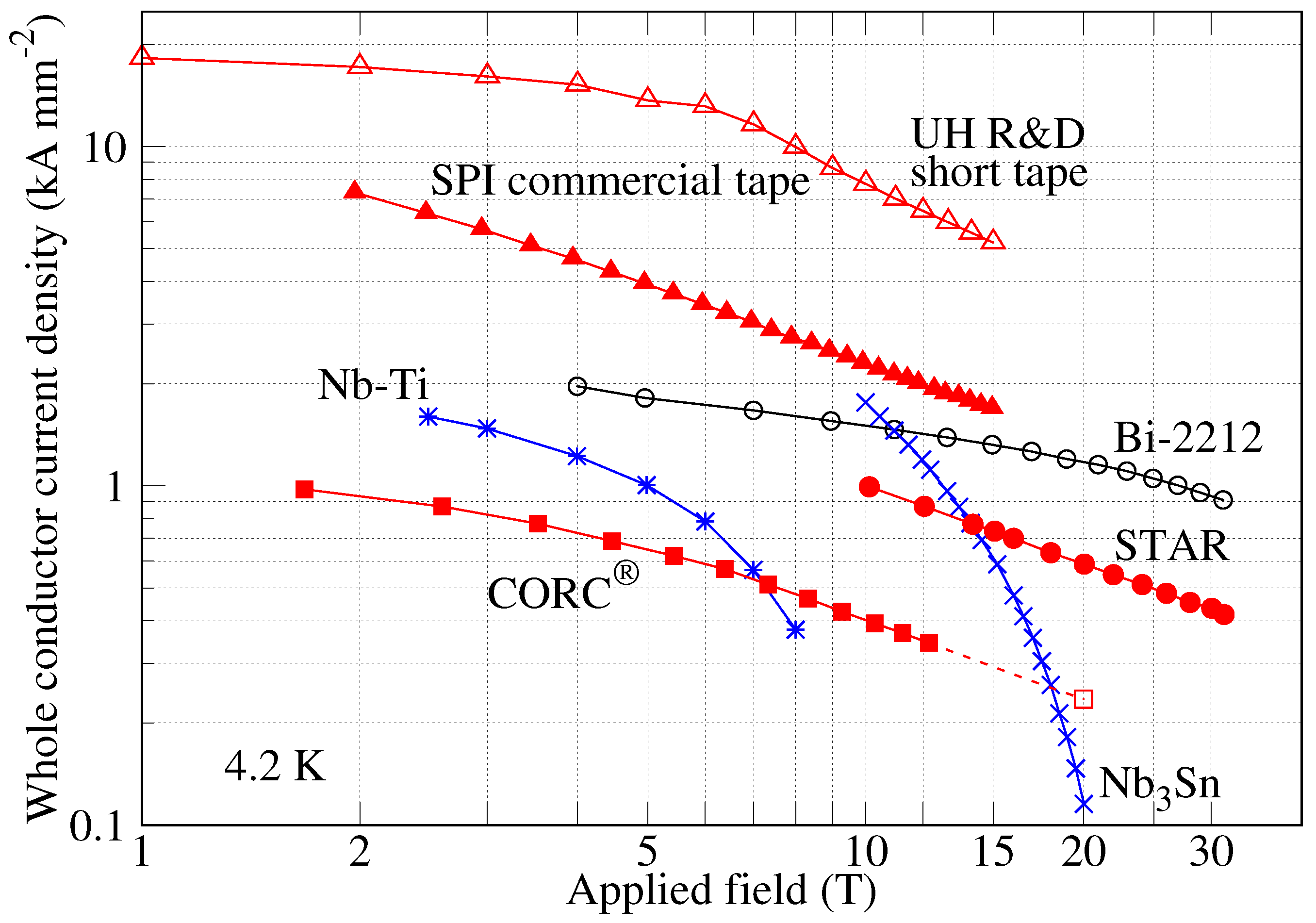
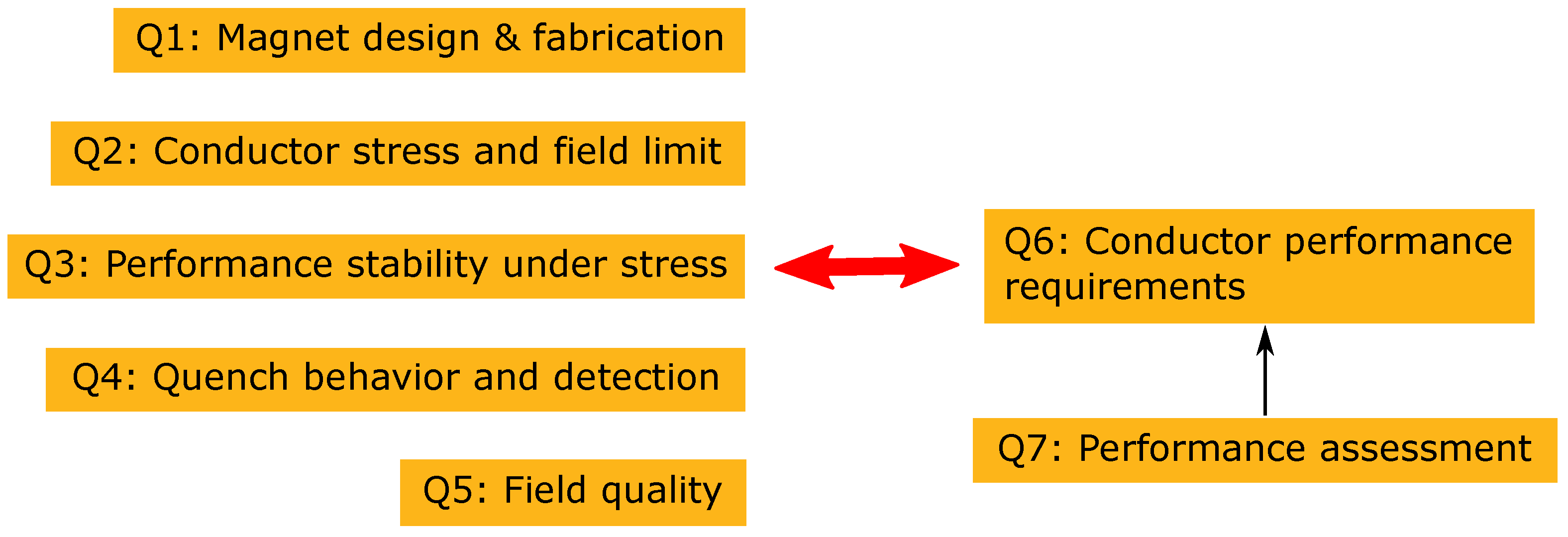
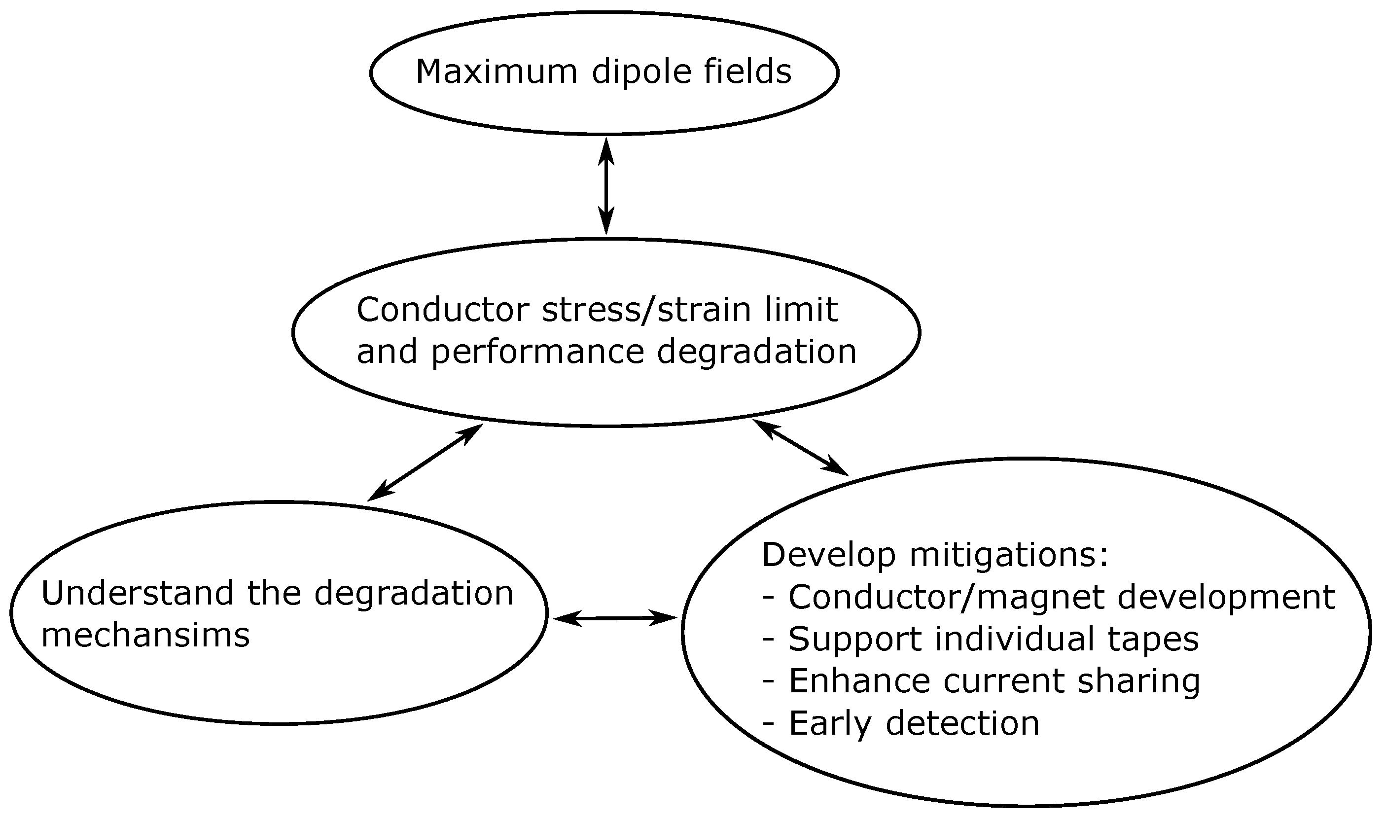
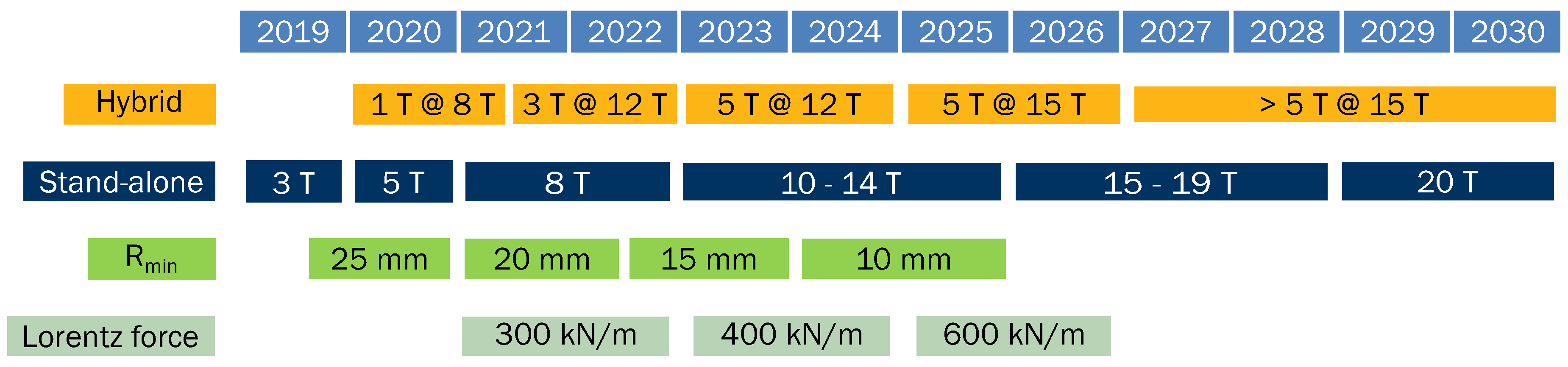
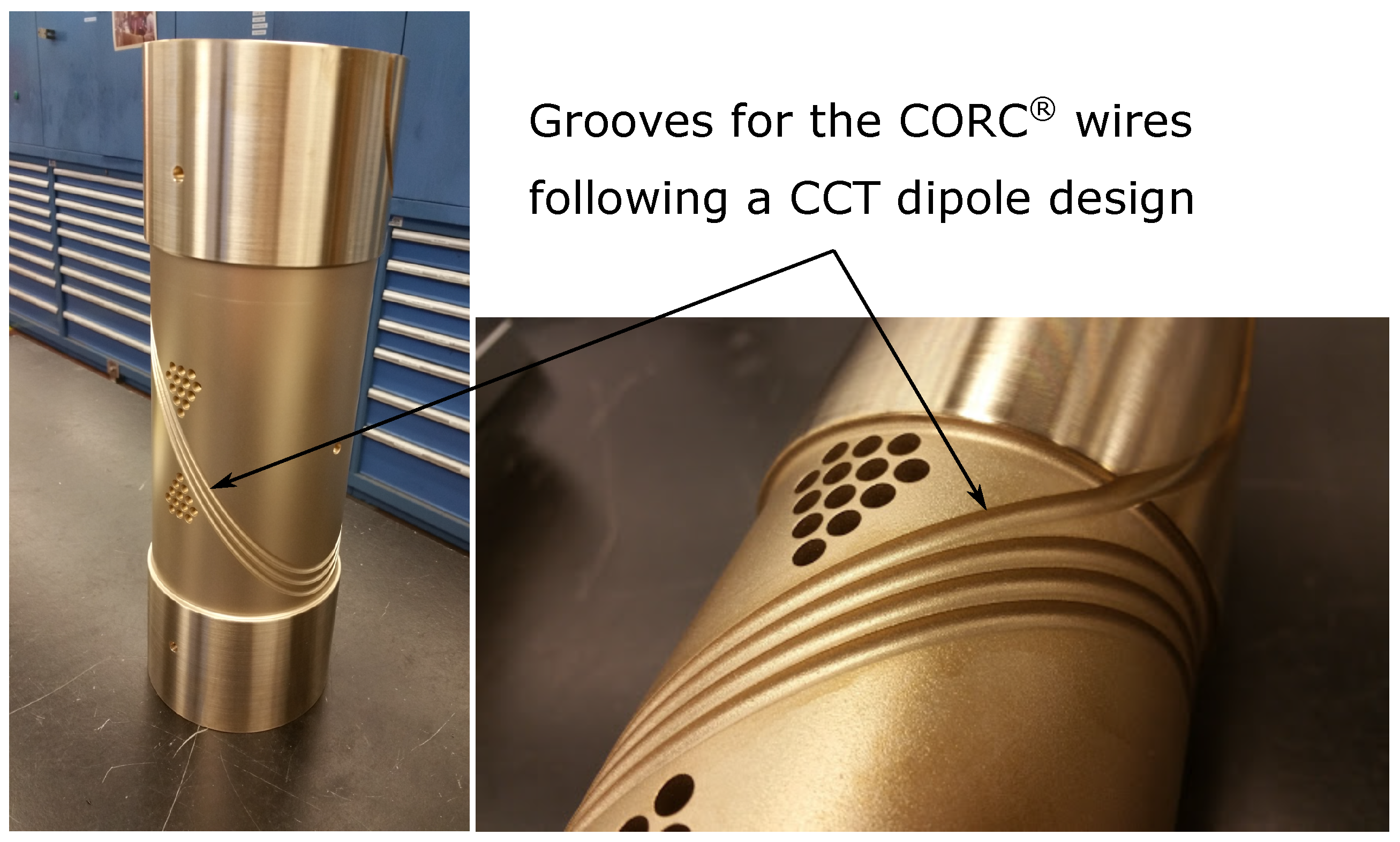
Table 1.
Typical properties, as of November 2019, of the technical superconducting materials that are currently available and relevant for high-field accelerator magnet applications.
Table 1.
Typical properties, as of November 2019, of the technical superconducting materials that are currently available and relevant for high-field accelerator magnet applications.
| Property | Unit | Nb–Ti | Nb3Sn | Bi-2212 | REBCO | ||
|---|---|---|---|---|---|---|---|
| Cable form | - | Rutherford cable | Roebel [29] | CORC® [30] | STAR [34] | ||
| Critical temperature | K | 9 | 18 | 90–95 | 93 | ||
| Upper critical field at 4.2 K | T | 11 [35] | 26 [8] | 105 [8] | 110 [36] | ||
| Upper critical field at 20 K | T | 0 | 0 | 9 [8] | 100 [36] | ||
| Typical wire diameter | mm | 1.065 [24] | 0.85 [27] | 0.80 [28] | 12×1.5 [37] | 3.7 [38] | 1.3 [34] |
| at 16 T, 4.2 K a | A mm−2 | 0 | 474 [39] | 1300 [28] | 964 b [40] | 310 c [38] | 695 d [34] |
| at 20 T, 4.2 K | A mm−2 | 0 | 123 [39] | 1180 [28] | 821 b [40] | 267 c [38] | 586 d [34] |
| Demonstrated bending radius | mm | 15 e | 13 e [41] | 10 e [42] | 4 e [43] | 30 [38] | 15 [34] |
| Effective filament diameter f | μm | 7 [24] | 55 [27] | 130 [44] | 2–5500 g [22] | 2000 g [38] | 1400–2500 g [34] |
| Magnetization at 4.2 K, 1 T h | mT | 10 i [45] | 270 [46] | 60 [47] | 716 j [48] | 502 [49] | TBD |
| Strand transposition | - | Full | Full | Partial | |||
| Peak heat treatment temperature | °C | N/A | 665 [27] | 892 [50] | N/A | ||
| Irreversible tensile strain limit | - | >1% [51] | 0.4% [52] | 0.3% [53,54] | 0.36% [55] | 0.85% [56] | TBD |
| Irreversible transverse stress limit | MPa | >200 [24] | 150–260 [57,58] | 60–TBD [59] | 370–440 [37] | 99 k [60] | TBD |
| Stabilizer fraction | - | 62% [24] | 55% [27] | 78% [61] | 20% [37] | 57% l [38] | 17% l [34] |
| Stabilizer RRR | - | 200 [24] | ≥150 [27] | 90–440 [61,62] | 13–69 m [63,64] | ||
| Joint resistance at 4.2 K | nΩ | <1 [65] | 1 | 1 [50] | <19 [66,67] | 2–6 [68] | TBD |
| Piece length (order of magnitude) | km | 1–10 [24] | 1–10 [27,69] | 1 [70] | 0.01–0.1 | ||
| Price of single strand/tape [25] | $ m−1 | 1.2 | 6.5 | 12.4 | 40 | ||
a Current density across the whole wire for the Rutherford cable cases, the individual tape for the Roebel cable case and the entire CORC® or STAR wires. Multiply by a packing factor such as 85% to obtain the current density averaged over the entire cross sectional area of the Rutherford or Roebel cable case. b Field perpendicular to the tape broad surface. c At a bending radius of 30 mm. d At a bending radius of 15 mm. e Easy-way bend along the cable broad surface. f Sub-element diameter for Nb3Sn and bundle diameter for Bi-2212 strands. g When the magnetic flux lines are in parallel with the broad surface of the REBCO tape, the REBCO layer thickness becomes the characteristic length scale for an effective filamnet size. When the flux lines are perpendicular to the tape broad surface, the width of the REBCO tape becomes the filament size. h The value at 1 T during the second up ramp from zero applied field following the virgin up and down ramp. i 2 K data. j A 9-tape Roebel cable with the field perpendicular to the cable broad surface. k Estimated based on a load of 115 kN m−1 with 3% reduction. Sample is not epoxy-impregnated. l The Cu core is considered as part of the stabilizer assuming it carries current during the superconducting to normal transition. m RRR of the Cu stabilizer in REBCO tapes. Similar RRR may also apply to the Cu core used in CORC® or STAR wires.
Table 2.
Synergies between the driving questions and the REBCO fusion magnet applications.
| Research Needs for High-Field REBCO Fusion Magnets and Conductors | Synergistic Driving Questions |
|---|---|
| Conductor design, fabrication and test | Section 3.1, Section 3.2, Section 3.3, Section 3.4, Section 3.5, Section 3.6 and Section 3.7 |
| Magnet design, fabrication and test | Section 3.1, Section 3.2, Section 3.3, Section 3.4, Section 3.5, Section 3.6 and Section 3.7 |
| Performance stability under Lorentz loads | Section 3.3, Section 3.4 and Section 3.6 |
| Quench behavior and detection | Section 3.4 and Section 3.6 |
| Demountable joints | Section 3.1 |
| Radiation hardness | Not addressed |
| AC losses | Section 3.5 and Section 3.6 |
| Operation above 4.2 K | Not addressed |
© 2019 by the authors. Licensee MDPI, Basel, Switzerland. This article is an open access article distributed under the terms and conditions of the Creative Commons Attribution (CC BY) license (http://creativecommons.org/licenses/by/4.0/).
Share and Cite
MDPI and ACS Style
Wang, X.; Gourlay, S.A.; Prestemon, S.O. Dipole Magnets above 20 Tesla: Research Needs for a Path via High-Temperature Superconducting REBCO Conductors. Instruments 2019, 3, 62. https://doi.org/10.3390/instruments3040062
AMA Style
Wang X, Gourlay SA, Prestemon SO. Dipole Magnets above 20 Tesla: Research Needs for a Path via High-Temperature Superconducting REBCO Conductors. Instruments. 2019; 3(4):62. https://doi.org/10.3390/instruments3040062
Chicago/Turabian StyleWang, Xiaorong, Stephen A. Gourlay, and Soren O. Prestemon. 2019. "Dipole Magnets above 20 Tesla: Research Needs for a Path via High-Temperature Superconducting REBCO Conductors" Instruments 3, no. 4: 62. https://doi.org/10.3390/instruments3040062