TomoPress—In Situ Synchrotron-Based Microtomography under Axial Load
by
Alexander Rack
1,*, 
Johannes Stroebel
2, 
Tatjana Rack
3,
Yves Dabin
1,
Christine Knabe
3,
Michael Stiller
3,
Paola Coan
2 and
Pierre Bleuet
4 1
ESRF—The European Synchrotron, F-38000 Grenoble, France
2
Faculty of Physics, Ludwig-Maximilians-Universität München, D-80799 Munich, Germany
3
Experimentelle Orofaziale Medizin, Philipps University Marburg, D-35039 Marburg, Germany
4
CEA, LETI, MINATEC Campus, F-38000 Grenoble, France
*
Author to whom correspondence should be addressed.
Instruments 2020, 4(2), 11; https://doi.org/10.3390/instruments4020011
Submission received: 26 February 2020
/
Revised: 14 April 2020
/
Accepted: 17 April 2020
/
Published: 22 April 2020
(This article belongs to the Collection Selected Papers from Instruments’ Editorial Board Members)
Abstract
:Computed tomography (CT) with hard X-rays is a mature technique that is in regular use to depict the interior of opaque specimens with spatial resolutions up to the micrometre range (microtomography or µCT). Short acquisition times and sophisticated contrast modes are accessible when synchrotron light sources are combined with microtomography—SR-µCT. Both features render SR-µCT as excellent probe to study delicate samples in situ, for example under mechanical load by deploying corresponding sample environments. The so-called TomoPress is such a device available within the public user programme of tomography beamline ID19 of the European Synchrotron Radiation Facility (ESRF). It allows one to study samples under high axial load (up to 500 N) with high spatial resolution up to the micrometer range. Different gauges are installed to allow online monitoring of the applied force. Constant humidity, temperature and wetting are routinely available as well. The article shall outline basic design principles of the press as well as parameters for its utilisation in a descriptive manner. Selected examples underline the potential of the device for such diverse fields as biomedical research, life sciences and materials research.
Keywords:
synchrotron; CT; microtomography; X-ray phase contrast; in situ; axial load; bone; wood; cartilage; failure; crack1. Introduction
So-called third generation synchrotron light sources with their bending magnet as well as insertion device beamlines offer an outstandingly high photon flux density [1]. For X-ray imaging, this offers the unique opportunity to work with a reduced bandwidth of the impinging radiation which increases the contrast. High photon flux also means short acquisition times which is crucial for time-resolved studies. Technically, exposure times down to the nanosecond range have been successfully used [2]. Furthermore, an extended distance to the source of up to several hundred meters allows for suppressing the influence of the finite source size on the image formation. Consequently, more sophisticated contrast modes like X-ray phase contrast become accessible [3]. Contrary to laboratory-based sources where X-ray imaging was the first technique ever used, the development of X-ray imaging with synchrotron sources began rather late in the 1980s when indirect X-ray detectors with high spatial resolution started to become routinely available [4]. Nowadays, hard X-ray beamlines which offer (full-field) imaging techniques within their portfolio are operating around the globe—for example the tomography beamline 8.3.2 at the Advanced Light Source (USA) [5], beamline 2-BM at the Advanced Photon Source (USA) [6], TopoTomo at ANKA (Germany) [7], the Imaging and Medical Beamline at the Australian Synchrotron [8], the BAMline at BESSY-II (Germany) [9], JEEP and I13 at Diamond Light Source (UK) [10,11], SYRMEP at Elettra (Italy) [12], X-ray imaging beamline at INDUS-2 (India) [13], IBL at PETRA3 (Germany) [14], tomocat at SLS (Switzerland) [15], ANATOMIX and PSICHÉ at Soleil (France) [16,17], BL47XU at SPRing8 (Japan) [18] or the future BEATS beamline at SESAME light source (Jordan) [19]. A more detailed overview is available by Rack et al. [20], as well as a general introduction on how to access synchrotron light sources by J. McCarthy [21]. Synchrotron radiation in combination with microtomography (SR-µCT) has already proven to be excellently suited to study dynamics inside specimens in three-dimensions and with high contrast [22,23,24]. Frequently, this is used to study samples under temperature changes, external mechanical forces or magnetic fields [25]. Commonly, highly specialised equipment is required in order to target one specific type of investigation. Selected highlights available in the literature are for example the study of dental implants under periodic load (chewing simulator) [26], tensile fatigue tests with tomographic acquisition rates of up to 20 Hz [27] or dedicated rigs to create conditions similar to those subsurface or at 10 km depth inside the earth crust (pressure, temperature and flow) [28,29]. This article sets its focus on axial load (up to 500 N) and high spatial resolution in the range of a few micrometer or less. Common studies within this parameter space cover deformation and crack propagation in (engineering) materials (e.g., aluminium alloys, fibre-reinforced materials) or bio- and biomedical materials (e.g., micromechanics in bone or insects) [22,23].
A proto-type of the TomoPress described in this article has been introduced by Bleuet et al. [30]—a press mainly developed to study (fracture in) bone at the tomography station of the former microscopy beamline ID22 of the ESRF [31,32]. As already mentioned above, frequently equipment is highly specialised for a specific scientific application—in case of the TomoPress it is the high spatial resolution, that is, restrictions are considered such as to consider axial loading of the sample only. The TomoPress is available for user experiments at microtomography beamline ID19 of the ESRF [33].
2. Method
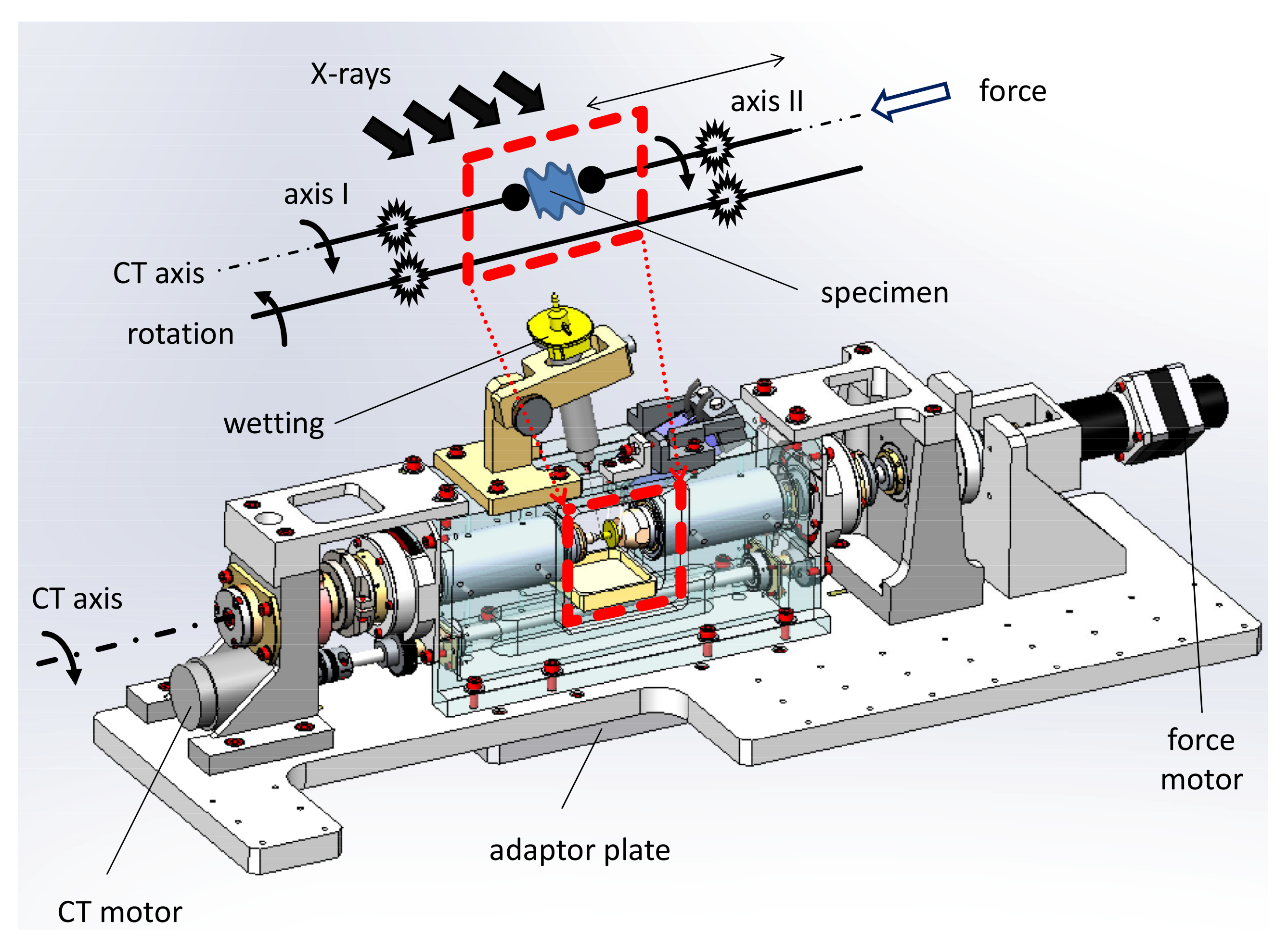
The layout and principle mode of operation of the TomoPress is sketched in Figure 1 while photos of selected configurations can be found in Figure 2. As already outlined in the introduction—being able to target a specific scientific question frequently requires highly specialised equipment. Here, the focus is put on axial load, that is, other means of mechanical testing such as torque or bending are not or at best only partially considered. As can be seen from the sketch, the TomoPress utilises a horizontal axis of rotation which is rather unusual: the original installation considered beamline ID22 located at a high-beta section of the ESRF storage ring with a corresponding large horizontal source size [31,32]. Here, in order to exploit the best coherence properties it was therefore beneficial to align the tomographic axis of rotation such that the (smaller) vertical source size dominates the contrast in-plane (axial) of the tomographic data set [34].
Despite targeting on axial loads only, several challenges have to be met for the design of such a press, namely, very low eccentricity and wobble for precise rotation (i.e., during tomographic acquisition) together with a tomographic axis which can glide in order to apply the external force. As can be seen from Figure 1, the design of the TomoPress is based on a single axis driven by a stepper motor which is connected to the two axes in charge of fixing and rotation of the sample via precise gear wheels. The gliding “axis II” (realised by high-precision ball bearings, not shown) is in touch with a micrometer screw which is driven by a stepper motor in order to apply the load, that is, the TomoPress can only load the sample, traction is not possible. Furthermore, the head of “axis II” contains a piezo element (type: p-series, Physik Instrumente (PI), Germany) in order to apply fast loads to the specimen with minor forces of up to 50 N. Such an option might be desirable in order to stimulate fatigue changes by applying fast loading cycles on top of the main load between consecutive scans. The “axis I” is commonly fixed but can be slightly manually shifted to allow for a precise sample mounting. The standard sample holders have a flat surface, that is, the sample is clamped (cf. Figure 2b). The holders are exchangeable, frequently they are custom-made for the specific scientific question (cf. for example Figure 2c). The eccentricity of the tomographic rotation has been estimated to be around 1 µm. The complete system is installed on a robust base plate which can be attached for example to standard goniometer elements in order to align the TomoPress with respect to the incoming beam and detector, cf. Figure 2. Commonly, at beamline ID19 the so-called HRtomo installation is used to host the press which offers a large flexibility in terms of detector installations and alignment procedures [35]. Specifications of the TomoPress are summarised in Table 1.
For detectors which do not fit in the aperture of the TomoPress where the sample is located (approximately 10 cm × 10 cm), the minimal propagation distance is limited to approximately 20 mm (ESRF beamlines frequently utilise indirect detector systems by the company OptiquePeter (Lentilly, France) [36]). Considering the rather large minimal propagation distance between sample and detector, edge-enhancement by means of X-ray phase contrast is frequently dominating the contrast [3]. Hence, applying single-distance phase retrieval techniques is the method of choice in order to achieve high sensitivity as well as a grey-scale distribution which is directly related to the local density of the specimen [37,38].
Different options are available to condition and monitor the sample between or during tomographic acquisition. As can be seen in Figure 1 and Figure 2—above the sample a syringe is placed. The latter is connected to a Applicateur-Doseur Ultra 1400 (Dosage 2000, Bougival, France) which is remote-controlled via a serial line. It allows for wetting the sample during or between scans. Once the central frame of the TomoPress which contains the sample is sealed with foils, cf. Figure 2b, a small local water tank can help to maintain constant humidity. Infrared lamps were successfully applied to keep specimens at constant (warm) temperature during experiments. A force sensor in the head of the clamp mount of “axis I” (type: XFL 212 by GS Sensor, France, read by a PHACABS, FGP Instrumentation, France) allows one for online monitoring of the applied load for up to 500 N (via a serial line). For more precise measurements, displacement sensors can be installed (Millimar C 1216 by Mahr, France), cf. Figure 2c.
3. Applications
This paragraph outlines the potential of the TomoPress along a few selected examples, namely tomographic studies of rat bone, wood and cartilage (all under axial load). Besides the examples shown here, the reader might refer to literature for studies on the mechanical behaviour of scaffolds under load as well spiders and their filter for vibrations and primate molar teeth [39,40,41].
3.1. Micromechanical Response of Bio-Regenerated Rat Bone
In modern dentistry the use of oral implants has become a common treatment to replace missing or lost teeth. But, bone resorption after tooth extraction frequently requires extensive bone regeneration before implants can be placed. Due to their ability to stimulate bone formation and to bond to bone resorbable bioactive ceramics are excellent bone substitute materials. This has led to their wide clinical use in both orthopaedics as well as dentistry—clinically bioactive ceramics are frequently used as bone substitute materials in the form of granules or blocks for bone grafting [42,43]. Bioactive ceramics are also excellent biomaterials for generating scaffolds for bone tissue engineering which can be used to reconstruct large segmental bone defects using adequate bone tissue engineering approaches. The latter combine scaffolds with mesenchymal stem cells and mircrovascular techniques, in order to facilitate adequate vascularization in segmental defects larger than 6 cm in width. Due to the rapid progress achieved in 3D printing technologies combining 3D printing with the patient’s computed tomography (CT) data allows fabricating scaffolds which exactly match the patient’s bony defect. The TomoPress is excellently suited to shed light on the mechanical properties of bone regenerated by using bone tissue engineering approaches. In this example we examined bioregenerated rat bone, that is, bone that was harvested from a large segmental defect in the rat femur which was regenerated using a tissue engineered synthetic bone graft—a 3D printed scaffold that contained homogenously distributed osteoblasts and mineralizing bone matrix upon implantation after seven days of in vitro perfusion cell culture prior to implantation [44].
Among the different techniques to reconstruct localized bony defects, the concept of so-called guided bone regeneration (GBR) is a predictable and well documented surgical approach. Here, frequently by implanting bio-degradable bioactive ceramics the local bone formation and regeneration is supported and even stimulated [43]. Novel bioceramics based on calcium orthophosphate with different levels of porosity have been developed recently, exhibiting an increased degradability compared to commercially existing tri-calcium phosphates [42]. They also can be used for fabricating scaffolds by 3D printing which combined with stem cells and an arteriovenous bundle are well-suited for the reconstruction of large segmental bone defects resulting from trauma or tumor surgery. In order to evaluate the suitability of these novel scaffolds and bone tissue engineering approach an animal study was performed: these scaffolds after being colonized with stem cells were implanted in large segmental defects in the rat femur in combination with an arteriovenous bundle which was created using a microvascular surgical technique. In order to shed light on the complex bioregeneration of this type of major bone defect non-destructively in three dimensions and due to its excellent density resolution, synchrotron microtomography (SR-µCT) has been frequently applied to study samples from these bioregenerated femurs (3 and 6 months after implantation using bone tissue engineering) [20]. Advancing research by employing SR-µCT in situ studies of bioregenerated bone under axial load offers the unique opportunity to access information about its micro-mechanical properties as well as elasticity, especially for the case when large segmental discontinuity bone defects are studied—for example, with respect to density variations and variations in osseous microarchitecture which lead to cracks under load [30,45].
As an example of this cutting-edge application, a rat bone sample from a segmental femoral defect which was regenerated using the tissue engineering approach outlined above was chosen. The sample was harvested 6 months after implantation of a 3D printed bioceramic scaffold colonized with cells in combination with an arteriovenous bundle into an artificially created 6 mm segmental discontinuity bony defect in the rat femur. Due to the rather long time after the implantation, the bioceramic scaffold can be expected to have largely resorbed and to have been replaced by newly formed bone. Hence, mature bone, which has been widely remodeled into the original osseous microarchitecture of the long bone is expected to be present in the specimen [20]. The sample was kept in a cold environment after harvesting, that is, it was shipped on dry ice to the ESRF for the experiment. Once mounted into the TomoPress, a commercial infrared lamp was used to keep the sample at a constant warm temperature. The TomoPress was mounted as shown in Figure 2a—capton windows sealed the sample chamber, a small water tank was inserted in order to maintain a rather high local humidity. In order to prevent the specimen from drying the wetting mechanism of the TomoPress was deployed by rinsing the bone with (destilled) water droplets between consecutive scans.
For the tomographic scans, a comparable high photon energy of 35 keV was chosen in order to minimize radiation damage to the wet sample while still maintaining sufficient contrast to see for example density changes. In order to reach sufficient photon flux density, beamline ID19 was operated in a pink-beam configuration: a so-called single-harmonic undulator (type u17.6, gap 15 mm) was chosen. Filters in the X-ray optical beam path (2 × 2.8 mm Al and 0.14 mm Cu) suppressed the fundamental harmonic: the remaining spectrum has a broad peak around 35 keV photon energy which is sufficiently intense for phase contrast X-ray imaging. As indirect high-resolution X-ray imaging detector a so-called revolver microscope was used (OptiquePeter, Lentilly, France) [36]. An Olympus 4× objective (0.16 NA) combined with an 2× eye-piece projects with 8× magnification the luminescence image of a 47 µm-thick GGG:Eu scintillator (Eu-doped GdGaO grown on top of an undoped GGG substrate) onto the sensor of a CCD camera (type: FReLoN e2v, 2048 × 2048 pixels, 15 µm pixel size) [46]. The effective pixel size of the detector is 1.85 µm. According to the chosen photon energy and pixel size, a propagation distance between sample and detector of 250 mm was used to benefit from increased sensitivity by means of X-ray phase contrast. Due to the rather slow rotation motor the TomoPress was operated in step-by-step acquisition mode (instead of continuous rotation which is nowadays the routine operation for tomographic acquisition at synchrotron light sources): 1500 projections covering 180 degree angular range were acquired (total scan time approximately 1 h). Tomographic reconstruction using standard filtered back projection was carried out using the ESRF inhouse developed software PyHST [47]. Prior to reconstruction single-distance phase retrieval was applied to the projection data in order to further boost the contrast [37]. A challenge faced during data acquisition is the fact that the sample cannot be removed for acquiring flat field images (beam background without sample). Therefore, only the mean over all projections could be used for normalisation [48]. The imperfect background correction leads to cupping-like artifacts in the final reconstructed slides. Between tomograhpic scans, the force motor was moved in equi-distant steps in order to apply load to the sample. The (nominal) applied force was measured using the force sensor in the head of “axis I”.
Example slices from a force series are depicted in Figure 3. The still intact sample already under a load of 45.5 N is shown in Figure 3a. The mature bone is clearly visible as well as soft tissue in the interior, that is, medullary canal of the long bone, and the already mentioned artifacts. Already in the following two force steps, 68.7 N and 85.8 N, severe cracks occur while the complete sample still stands the load, that is, the applied force is not decreasing. The following force step shows that substantial regions of the sample are already shattered which partially can explain the constant nominal force value measured which might be related to re-arrangements inside the broken bone pieces. The pre-final force step sees all region of the bone populated with cracks before in the final step the complete sample is damaged, that is, the measured force drops to almost zero.
3.2. Crack Propagation: The Case of Wood
Engineered wood components are wide spread, that is, wood is among the most widely used structural materials in the world. Failure of wood constructions is frequently related to fatigue—An accumulation of irreversible damages inside the material. This complex behaviour for the case of wood is still not well understood. As an example application of the TomoPress in the fields of materials research studying the fracture of wood is described in this section. It is a well-known fact that the structure of wood sufficiently changes when a substantial load is applied [49]. Depending on a wide range of loading conditions, these changes can reveal in different forms. The term “fracture” for example is used when modifications lead to new surfaces and broken bonds. The term “fracture” describes the fact that the material can not carry load anymore. Fracture can propagate slow with minor increments or fast and catastrophic, depending on the loading conditions. Failure can result from many mechanism of which fracture is not a mandatory condition. Vice versa fracture does also not automatically lead to failure. Wood establishes a specific structure during the growth of a tree. Consequently, fracture and failure strongly depend on the orientation of load with respect to the axis of growth. In the literature frequently six different fracture orientations relative to the growth orientation are defined. For each different orientation the various crack modes have to be considered and hence, leading to a substantial amount of fracture cases to be considered. As a consequence for example up to now there is no standard method established which could be used to measure fracture toughness [49]. Here the TomoPress offers unique capabilities to correlate wood properties with for example the morphology of fracture. Due to its in situ capabilities, the TomoPress would even allow one to study failure of wood under different environmental conditions such as moisture changes which can substantially alter the plant cell wall structure [50].
The experiment was again carried out on beamline ID19 (ESRF). For the sake of a simple sample preparation a small piece of wood was harvested from a plain tooth pick which perfectly fits in the field of view for high-resolution microtomography. In order to have a balance between contrast as well as dose to the sample a photon energy of 26.1 keV was chosen. Beamline ID19 was operated again in a pink configuration to reach sufficient high photon flux density for short exposure times: the radiation emitted by a so-called single-harmonic undulator (type: u13, gap 11.5 mm) was only filtered by a 1 mm-thick diamond absorber as well as 1.4 mm Al (to suppress softer parts of the emitted spectrum) and the mandatory 0.5 mm-thick Be exit window. The X-ray image detector is exactly the same as in the previous section: an indirect system consisting of scintillator, visible light optics and CCD camera, operating with an effective pixel size of 1.85 µm. According to the pixel size and photon energy chosen a propagation distance between sample and detector of 350 mm was set in order to benefit from propagation-based phase-enhanced edge contrast. One thousand projection images were recorded over a 180 degree angular range. No phase-retrieval was applied before tomographic reconstructions.
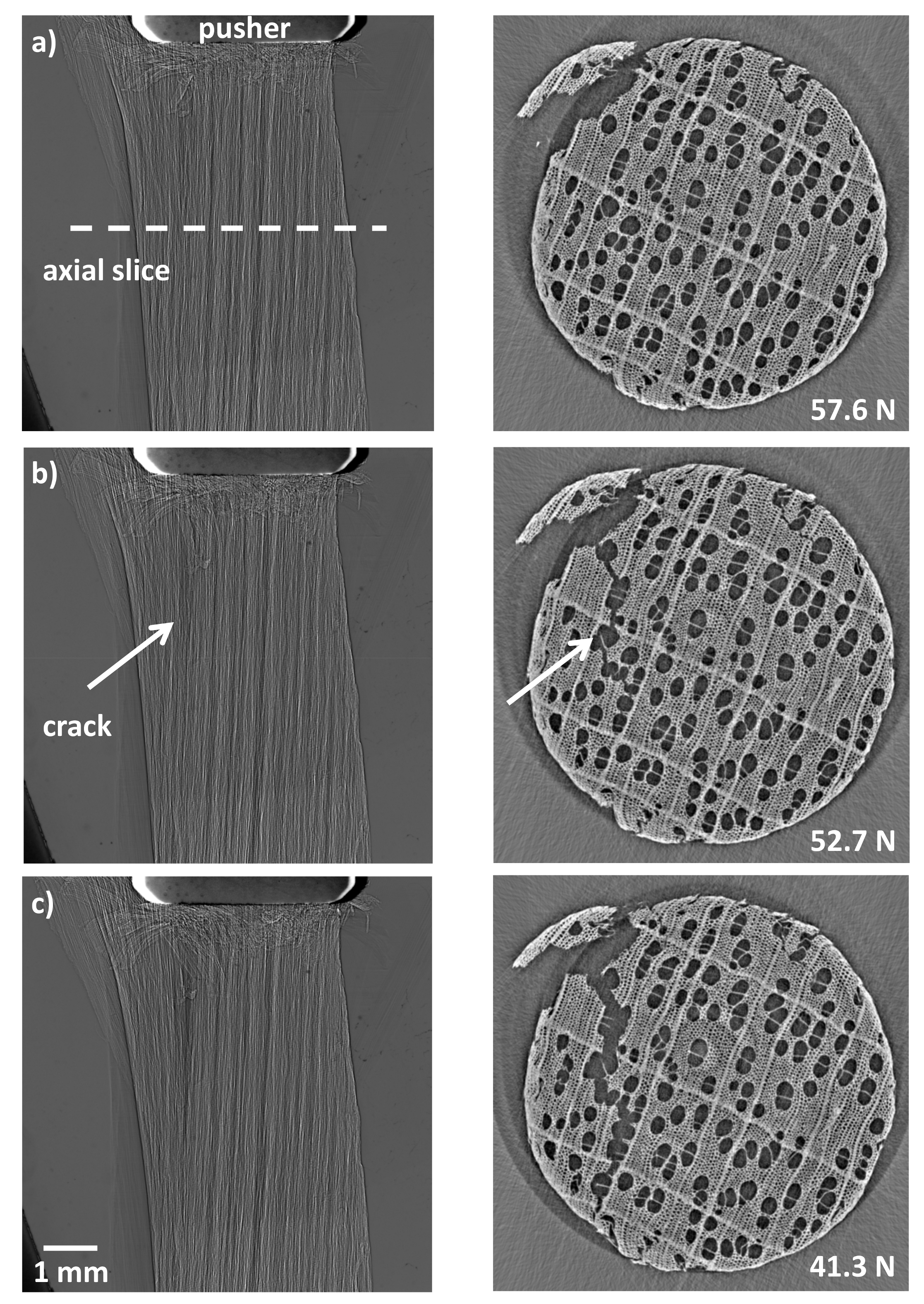
Images from the force series applied until a crack occurred in the sample are shown in Figure 4. For each tomographic slice a corresponding radiographic projection image from the corresponding data set is shown as well. The still intact sample already under load can be seen in Figure 4a. The high resolution reached with the TomoPress allows to depict fine details inside the specimen even under an external load of nominal 57.6 N. One force step further a crack starts to propagate through the sample, cf. Figure 4b. The nominal force is reduced to 52.7 N due to the release of stress. One more force step and the crack propagates through the complete sample, cf. Figure 4c, accordingly the measured force is further reduced.
3.3. Microstructure of Cartilage under Load
The mechanisms under which cartilage tissue reacts to load and how it relaxes are not well understood yet. Daily activities such as walking, running or sports expose the articular cartilage to stress and pressure. The biomechanical response of the tissue may strongly vary between healthy and pathological conditions. In order to shed light on these processes, experiments have been designed to image cartilage plugs extracted from human knee joints while applying different pressures to them with the TomoPress. Here, the use of phase-enhanced X-ray microtomography allows one to visualize in three dimensions the tissue’s morphological changes induced by the compression [51]. The objective of this work is to develop an experimental and analytical methodology to visualize and quantify the cartilage structure, cell distribution and the tissue mechanical behavior at rest and under load conditions. This protocol can be applied to healthy and degenerated tissue specimens as well. For a sound description of the sample preparation, further data processing and complete description of all experimental results the reader is referred to Reference [52].
For this study, series of samples were harvested from two human knees—thirteen plugs were drilled from the femur and patella cartilage. According to the regulations for experiments involving cadaveric samples, this study was waived by the ethics committee of the Ludwig-Maximilians-University, Munich, Germany. The required informed consent was obtained from the legally authorized/next of kin of the deceased prior to the extraction of the patella in accordance with the relevant guidelines and regulations by the forensic medicine department of the Ludwig-Maximilians-University, Munich, Germany including testing for infectious diseases. The osteochondral plugs had a diameter of about 7 mm and consisted of a cartilage part and a bone part. The sample later shown can be considered as healthy and origins from the femur cartilage (total length: 16.4 mm, cartilage thickness: 2.9 mm, bone thickness: 12.6 mm, plug diameter: 7.2 mm). Tomographic acquisition was again carried out at beamline ID19 (ESRF): a pink undulator type u13 with a photon energy of 26.1 keV delivered the required high photon flux density. Operating the beamline with minimal optical elements, that is, only attenuators (1 mm diamond, 0.7 mm aluminum) and a beryllium window (0.5 mm) ensures high sensitivity by means of X-ray phase contrast. In order to image the complete specimen, a medium resolution detector was chosen: two lenses (Hasselblad, focal length 300 mm and 100 mm) facing each other in tandem-like geometry project the luminescence image of a GGG:Eu (Eu-doped GdGaO, 1000 µm thick) onto the sensor of the inhouse-developed CCD camera FReLoN (type: e2v) [53]. The corresponding effective pixel size of the indirect detector is 5.1 µm. According to the large pixel size a propagation distance of 5 m was realised to ensure high sensitivity. 2000 projection images over an angular range of 180 degree were acquired (0.2 s exposure time per image). Dedicated sample mounts were made fitting to the dimensions of the specimen. Additionally, samples were kept during the load series confined in a plexiglass cylinder with saline solution to avoid tissue dehydration. The cylinder supported mechanical stability of the sample when the force was applied, that is, prevented the sample from bending or lateral gliding. Tomographic reconstruction was carried out again by using the ESRF in-house developed software PyHST.
The resulting tomographic images consist of axial slices, which represent virtually the entire volume of a osteochondral plug. Using then the ImageJ software each volume image was resliced to obtain a sagittal view on the sample, which gives insights into the different cartilage layers. Close to the bone surface, the chondrocytes/chondrons are vertically aligned. Close to the cartilage surface, chondrocytes are horizontally aligned. The white (brighter) color in the following images represents material with high electron density, like bone, and the black parts have instead a low electron density. In Figure 5a, the cartilage is on bottom of the image, while the bone is above. The shown sagittal image correspond to a case in which no pressure is applied to the sample (sample at rest). The black dots within the cartilage are chondrons, that is, chondrocytes with peri-cellular matrix; the gray part is the interterritorial matrix. The superficial zone is not visible for this experiment as the top cartilage layer is in contact with the TomoPress. For all images in Figure 5, the contrast function is chosen such that the visibility of the soft tissue is maximised. As a consequence, the grey values for bone are partially saturated.
When no pressure is applied the cartilage matrix is very homogenous. This changes drastically when applying a force—the interterritorial matrix gets deformed, cf. tomographic slice of the osteochondral plug in Figure 5b. The compression is visible by the lateral enlargement of the cartilage tissue. The compression of the cartilage causes a reduction in height which is of 29% with respect to condition at 0 N (cartilage at rest) for the case 12 N load and of 53% (Figure 5b) for the case of 24 N load (Figure 5c). The lateral expansion of cartilage is comparable in both cases.
4. Summary
The loading device TomoPress, as described in this article, is available for experiments in the frame of the public user programme of beamline ID19 of the European Synchrotron Radiation Facility. The system allows for studying specimens with high spatial resolution and high contrast under axial load of up to 500 N. Several example experiments such as fracture in bone and wood or the dynamic response of cartilage under load have shown the huge potential of the TomoPress for in situ studies ranging from diverse scientific fields such as materials research to biomedical applications. Successful experiments using the TomoPress can also be found in the literature, for example, a study on the mechanical behaviour of scaffolds under load or spiders and their filter for vibrations and primate molar teeth [39,40,41].
Author Contributions
The authors contributed in the following topics: conceptualization, P.B., A.R. and Y.D.; methodology, J.S., C.K., M.S., P.B., Y.D., P.C. and A.R.; formal analysis, A.R., J.S. and T.R.; investigation, A.R., T.R., C.K., M.S., P.C. and J.S.; writing—original draft preparation, A.R., J.S. and C.K.; writing—review and editing, C.K., M.S., T.R., P.C. and P.B.; visualization, A.R., T.R. and J.S. All authors have read and agreed to the published version of the manuscript.
Funding
The research of Christine Knabe was funded by Deutsche Forschungsgemeinschaft (DFG) grant number GZ: KN 377/7-1 and BE 1339/33-1. Beamtime was granted by the European Synchrotron Radiation Facility in the frame of proposals MD-820, MD-1015 and MD-1054. The project of Johannes Stroebel and Paola Coan was funded by Deutsche Forschungsgemeinschaft (Cluster of Excellence) Munich Center for Advanced Photonics (EXE158).
Acknowledgments
We acknowlege J.-P. Valade, E. Boller, E. Papillon, P. Bernard, T. Mannings (ESRF) and Florian Bonatz (h_da) for general support to integrate the TomoPress at beamline ID19 of the ESRF. Marco Lopez (Philipps University Marburg) helped during beamtime MD-820, Valentina Cantelli (HZDR) during MD-1015 and MD-1054. We thank Annie Horng for the procurement of the cartilage specimens and for the medical data interpretation and Nicola Vigano (ESRF) for proof reading.
Conflicts of Interest
The authors declare no conflict of interest. The funders had no role in the design of the study; in the collection, analyses, or interpretation of data; in the writing of the manuscript, or in the decision to publish the results.
References
- Wiedemann, H. Synchrotron Radiation; Springer: Berlin, Germany, 2002. [Google Scholar] [CrossRef]
- Olbinado, M.P.; Just, X.; Gelet, J.L.; Lhuissier, P.; Scheel, M.; Vagovic, P.; Sato, T.; Graceffa, R.; Schulz, J.; Manusco, A.; et al. MHz frame rate hard X-ray phase-contrast imaging using synchrotron radiation. Opt. Express 2017, 25, 13857–13871. [Google Scholar] [CrossRef]
- Cloetens, P.; Barrett, R.; Baruchel, J.; Guigay, J.P.; Schlenker, M. Phase objects in synchrotron radiation hard X-ray imaging. J. Phys. D 1996, 29, 133–146. [Google Scholar] [CrossRef]
- Bonse, U.; Busch, F. X-ray computed microtomography (μCT) using synchrotron radiation (SR). Prog. Biophys. Mol. Biol. 1996, 65, 133–169. [Google Scholar] [CrossRef]
- MacDowell, A.A.; Parkinson, D.Y.; Haboub, A.; Schaible, E.; Nasiatka, J.R.; Yee, C.A.; Jameson, J.R.; Ajo-Franklin, J.B.; Brodersen, C.R.; McElrone, A.J. X-ray micro-tomography at the Advanced Light Source. In Developments in X-ray Tomography VIII; Stock, S.R., Ed.; SPIE Press: Bellingham, WA, USA, 2012; Volume 8506, p. 850618. [Google Scholar] [CrossRef]
- Wang, Y.; De Carlo, F.; Mancini, D.C.; McNulty, I.; Tieman, B.; Bresnahan, J.; Foster, I.; Insley, J.; Lange, P.; Laszewski, G.; et al. A high-throughput X-ray microtomography system at the Advanced Photon Source. Rev. Sci. Instrum. 2001, 72, 2062–2068. [Google Scholar] [CrossRef] [Green Version]
- Rack, A.; Weitkamp, T.; Bauer Trabelsi, S.; Modregger, P.; Cecilia, A.; dos Santos Rolo, T.; Rack, T.; Haas, D.; Simon, R.; Heldele, R.; et al. The micro-imaging station of the TopoTomo beamline at the ANKA synchrotron light source. Nucl. Instrum. Meth. B 2009, 267, 1978–1988. [Google Scholar] [CrossRef]
- Hausermann, D.; Hall, C.; Maksimenko, A.; Campbell, C. The Imaging and Medical Beam Line at the Australian Synchrotron. AIP Conf. Proc. 2010, 1266, 3–9. [Google Scholar] [CrossRef] [Green Version]
- Rack, A.; Zabler, S.; Müller, B.R.; Riesemeier, H.; Weidemann, G.; Lange, A.; Goebbels, J.; Hentschel, M.; Görner, W. High resolution synchrotron-based radiography and tomography using hard X-rays at the BAMline (BESSY II). Nucl. Instrum. Method A 2008, 586, 327–344. [Google Scholar] [CrossRef]
- Rau, C.; Wagner, U.; Pesic, Z.; De Fanis, A. Coherent imaging at the Diamond beamline I13. Phys. Status Solidi A 2011, 208, 2522–2525. [Google Scholar] [CrossRef]
- Drakopoulos, M.; Connolley, T.; Reinhard, C.; Atwood, R.; Magdysyuk, O.; Vo, N.; Hart, M.; Connor, L.; Humphreys, B.; Howell, G.; et al. I12: The Joint Engineering, Environment and Processing (JEEP) beamline at Diamond Light Source. J. Synchrotron Radiat. 2015, 22, 828–838. [Google Scholar] [CrossRef]
- Tromba, G.; Longo, R.; Abrami, A.; Arfelli, F.; Astolfo, A.; Bregant, P.; Brun, F.; Casarin, K.; Chenda, V.; Dreossi, D.; et al. The SYRMEP Beamline of Elettra: Clinical Mammography and Biomedical Applications. AIP Conf. Proc. 2010, 1266, 18–23. [Google Scholar] [CrossRef]
- Agrawal, A.K.; Singh, B.; Kashyap, Y.S.; Shukla, M.; Sarkar, P.S.; Sinha, A. Design, development and first experiments on the X-ray imaging beamline at Indus-2 synchrotron source RRCAT, India. J. Synchrotron Radiat. 2015, 22, 1531–1539. [Google Scholar] [CrossRef] [PubMed]
- Haibel, A.; Beckmann, F.; Dose, T.; Herzen, J.; Ogurreck, M.; Müller, M.; Schreyer, A. Latest developments in microtomography and nanotomography at PETRA III. Powder Differ. 2010, 25, 161–164. [Google Scholar] [CrossRef] [Green Version]
- Stampanoni, M.; Groso, A.; Isenegger, A.; Mikuljan, G.; Chen, Q.; Meister, D.; Lange, M.; Betemps, R.; Henein, S.; Abela, R. TOMCAT: A beamline for Tomographic Microscopy and Coherent radiology experiments. AIP Conf. Proc. 2007, 879, 848–851. [Google Scholar] [CrossRef] [Green Version]
- Weitkamp, T.; Scheel, M.; Giorgetta, J.; Joyet, V.; Roux, V.L.; Cauchon, G.; Moreno, T.; Polack, F.; Thompson, A.; Samama, J. The tomography beamline ANATOMIX at Synchrotron SOLEIL. J. Phys. Conf. Ser. 2017, 849, 012037. [Google Scholar] [CrossRef] [Green Version]
- King, A.; Guignot, N.; Zerbino, P.; Boulard, E.; Desjardins, K.; Bordessoule, M.; Leclerq, N.; Le, S.; Renaud, G.; Cerato, M.; et al. Tomography and imaging at the PSICHE beam line of the SOLEIL synchrotron. Rev. Sci. Instrum. 2016, 87, 093704. [Google Scholar] [CrossRef] [Green Version]
- Uesugi, K.; Hoshino, M.; Takeuchi, A.; Suzuki, Y.; Yagi, N.; Nakano, T. Development of fast (sub-minute) micro-tomography. AIP Conf. Proc. 2010, 1266, 47–50. [Google Scholar] [CrossRef]
- Einfeld, D.; Hasnain, S.; Sayers, Z.; Schopper, H.; Winick, H. SESAME, a third generation synchrotron light source for the Middle East region. Radiat. Phys. Chem. 2004, 71, 693–700. [Google Scholar] [CrossRef] [Green Version]
- Rack, A.; Tafforeau, P.; Riesemeier, H.; Stiller, M.; Dalügge, O.; Rack, T.; Stiller, F.; Knabe, C. 3.4 Developments in High-Resolution CT: Studying Bioregeneration by Hard X-ray Synchrotron-Based Microtomography. In Comprehensive Biomaterials II; Ducheyne, P., Ed.; Elsevier: Oxford, UK, 2017; pp. 58–77. [Google Scholar] [CrossRef]
- McCarthy, J. ESRF: A Quest for Excellence in Service to Users. Synchrotron Radiat. News 2017, 30, 31–36. [Google Scholar] [CrossRef]
- Banhart, J. (Ed.) Advanced Tomographic Methods in Materials Research and Engineering; Oxford University Press: Oxford, UK, 2008. [Google Scholar] [CrossRef] [Green Version]
- Stock, S.R. MicroComputed Tomography: Methodology and Applications, 2nd ed.; CRC Press: Boca Raton, FL, USA; Taylor and Francis Group: London, UK; New York, NY, USA, 2019. [Google Scholar] [CrossRef]
- Stock, S. Recent advances in X-ray microtomography applied to materials. Int. Mater. Rev. 2008, 53, 129–181. [Google Scholar] [CrossRef]
- Maire, E.; Withers, P. Quantitative X-ray tomography. Int. Mater. Rev. 2014, 59, 1–43. [Google Scholar] [CrossRef] [Green Version]
- Wiest, W.; Zabler, S.; Rack, A.; Fella, C.; Balles, A.; Nelson, K.; Schmelzeisen, R.; Hanke, R. In situ microradioscopy and microtomography of fatigue-loaded dental two-piece implants. J. Synchrotron Radiat. 2015, 22, 1492–1497. [Google Scholar] [CrossRef] [PubMed]
- Maire, E.; Le Bourlot, C.; Adrien, J.; Mortensen, A.; Mokso, R. 20 Hz X-ray tomography during an in situ tensile test. Int. J. Fract. 2016, 200, 3–12. [Google Scholar] [CrossRef]
- Renard, F.; Cordonnier, B.; Dysthe, D.K.; Boller, E.; Tafforeau, P.; Rack, A. A deformation rig for synchrotron microtomography studies of geomaterials under conditions down to 10 km depth in the Earth. J. Synchrotron Radiat. 2016, 23, 1030–1034. [Google Scholar] [CrossRef] [PubMed]
- Voltolini, M.; Barnard, H.; Creux, P.; Ajo-Franklin, J. A new mini-triaxial cell for combined high-pressure and high-temperature in situ synchrotron X-ray microtomography experiments up to 400 °C and 24 MPa. J. Synchrotron Radiat. 2019, 26, 238–243. [Google Scholar] [CrossRef]
- Bleuet, P.; Roux, J.P.; Dabin, Y.; Boivin, G. In situ microtomography study of human bones under strain with synchrotron radiation. In Developments in X-ray Tomography IV; Bonse, U., Ed.; SPIE Press: Bellingham, WA, USA, 2004; Volume 5535, pp. 129–136. [Google Scholar] [CrossRef]
- Weitkamp, T.; Raven, C.; Snigirev, A.A. Imaging and microtomography facility at the ESRF beamline ID 22. In Developments in X-ray Tomography II; International Society for Optics and Photonics; Bonse, U., Ed.; SPIE Press: Bellingham, WA, USA, 1999; Volume 3772, pp. 311–317. [Google Scholar] [CrossRef]
- Martínez-Criado, G.; Tucoulou, R.; Cloetens, P.; Bleuet, P.; Bohic, S.; Cauzid, J.; Kieffer, I.; Kosior, E.; Labouré, S.; Petitgirard, S.; et al. Status of the hard X-ray microprobe beamline ID22 of the European Synchrotron Radiation Facility. J. Synchrotron Radiat. 2012, 19, 10–18. [Google Scholar] [CrossRef]
- Weitkamp, T.; Tafforeau, P.; Boller, E.; Cloetens, P.; Valade, J.P.; Bernard, P.; Peyrin, F.; Ludwig, W.; Helfen, L.; Baruchel, J. Status and evolution of the ESRF beamline ID19. In AIP Conference Proceedings; Denecke, M., Walker, C.T., Eds.; American Institute of Physics: College Park, MD, USA, 2010; Volume 1221, pp. 33–38. [Google Scholar] [CrossRef]
- Cloetens, P.; Guigay, J.P.; De Martino, C.; Baruchel, J.; Schlenker, M. Fractional Talbot imaging of phase gratings with hard x rays. Opt. Lett. 1997, 22, 1059–1061. [Google Scholar] [CrossRef]
- Rack, A.; Weitkamp, T.; Assoufid, L.; Rack, T.; Zanette, I.; Morawe, C.; Kluender, R.; David, C. Protocol to study wavefront preservation capabilities of reflective X-ray optics with coherent synchrotron light. Nucl. Instrum. Method A 2013, 710, 101–105. [Google Scholar] [CrossRef]
- Douissard, P.A.; Cecilia, A.; Rochet, X.; Chapel, X.; Martin, T.; van de Kamp, T.; Helfen, L.; Baumbach, T.; Luquot, L.; Xiao, X.; et al. A versatile indirect detector design for hard X-ray microimaging. J. Instrum. 2012, 7, P09016. [Google Scholar] [CrossRef]
- Paganin, D.; Mayo, S.C.; Gureyev, T.E.; Miller, P.R.; Wilkins, S.W. Simultaneous phase and amplitude extraction from a single defocused image of a homogeneous object. J. Microsc. Oxf. 2002, 206, 33–40. [Google Scholar] [CrossRef]
- Weitkamp, T.; Haas, D.; Wegrzynek, D.; Rack, A. ANKAphase: Software for single-distance phase retrieval from inline X-ray phase-contrast radiographs. J. Synchrotron Radiat. 2011, 18, 617–629. [Google Scholar] [CrossRef]
- Erko, M.; Younes-Metzler, O.; Rack, A.; Zaslansky, P.; Young, S.L.; Milliron, G.; Chyasnavichyus, M.; Barth, F.G.; Fratzl, P.; Tsukruk, V.; et al. Micro- and nano-structural details of a spider’s filter for substrate vibrations: Relevance for low-frequency signal transmission. J. R. Soc. Interface 2015, 12, 20141111. [Google Scholar] [CrossRef] [PubMed]
- Charles-Harris, M.; del Valle, S.; Hentges, E.; Bleuet, P.; Lacroix, D.; Planell, J.A. Mechanical and structural characterisation of completely degradable polylactic acid/calcium phosphate glass scaffolds. Biomaterials 2007, 28, 4429–4438. [Google Scholar] [CrossRef] [PubMed]
- Bemmann, M.; Schulz-Kornas, E.; Hammel, J.U.; Hipp, A.; Moosmann, J.; Herrel, A.; Rack, A.; Radespiel, U.; Zimmermann, E.; Kaiser, T.M.; et al. 3D movement analysis of primate molar teeth under load using synchrotron X-ray microtomography. J. R. Soc. Interface 2020, submitted. [Google Scholar]
- Knabe, C.; Koch, C.; Rack, A.; Stiller, M. Effect of β-tricalcium phosphate particles with varying porosity on osteogenesis after sinus floor augmentation in humans. Biomaterials 2008, 29, 2249–2258. [Google Scholar] [CrossRef] [PubMed]
- Knabe, C.; Ducheyne, P. Cellular Response to Bioactive Ceramics. In Bioceramics and Their Clinical Applications; Kokubo, T., Ed.; Woodhead Publishing Inc.: Cambridge, UK, 2008; pp. 133–164. [Google Scholar] [CrossRef]
- Adel-Khattab, D.; Giacomini, F.; Peleska, B.; Gildenhaar, F.; Berger, G.; Gomes, C.; Linow, U.; Hardt, M.; Günster, J.; Stiller, M.; et al. Development of a synthetic tissue engineered 3D printed bioceramic-based bone graft with homogenously distributed osteoblasts and mineralizing bone matrix in vitro. J. Tissue Eng. Regen. Med. 2018, 12, 44–58. [Google Scholar] [CrossRef]
- Zhai, X.; Gao, J.; Nie, Y.; Guo, Z.; Kedir, N.; Claus, B.; Sun, T.; Fezzaa, K.; Xiao, X.; Chen, W.W. Real-time visualization of dynamic fractures in porcine bones and the loading-rate effect on their fracture toughness. J. Mech. Phys. Sol. 2019, 131, 358–371. [Google Scholar] [CrossRef]
- Labiche, J.C.; Mathon, O.; Pascarelli, S.; Newton, M.A.; Ferre, G.G.; Curfs, C.; Vaughan, G.; Homs, A.; Carreiras, D.F. The fast readout low noise camera as a versatile X-ray detector for time resolved dispersive extended X-ray absorption fine structure and diffraction studies of dynamic problems in materials science, chemistry, and catalysis. Rev. Sci. Instrum. 2007, 78, 0901301. [Google Scholar] [CrossRef]
- Mirone, A.; Brun, E.; Gouillart, E.; Tafforeau, P.; Kieffer, J. The PyHST2 hybrid distributed code for high speed tomographic reconstruction with iterative reconstruction and a priori knowledge capabilities. Nucl. Instrum. Method Phys. Res. B 2014, 324, 41–48. [Google Scholar] [CrossRef] [Green Version]
- Nieuwenhove, V.V.; Beenhouwer, J.D.; Carlo, F.D.; Mancini, L.; Marone, F.; Sijbers, J. Dynamic intensity normalization using eigen flat fields in X-ray imaging. Opt. Express 2015, 23, 27975–27989. [Google Scholar] [CrossRef] [Green Version]
- Smith, I.; Landis, E.; Gong, M. Fracture and Fatigue in Wood; John Wiley & Sons Ltd.: Chichester, UK; Hoboken, NJ, USA, 2003. [Google Scholar]
- Zabler, S.; Paris, O.; Burgert, I.; Fratzl, P. Moisture changes in the plant cell wall force cellulose crystallites to deform. J. Struct. Biol. 2010, 171, 133–141. [Google Scholar] [CrossRef]
- Issever, A.S.; Diederichs, G.; Majumdar, S.; Rogalla, P.; Hamm, B.K.; Lange, A.; Harwardt, M.; Hentschel, M.P.; Mueller, B.R. Analyser-based tomography images of cartilage. J. Synchrotron Radiat. 2008, 15, 525–527. [Google Scholar] [CrossRef] [PubMed]
- Stroebel, J. A Multi-Scale Imaging Approach to Understand Osteoarthritis Development. Ph.D. Thesis, Ludwig-Maximilians-Universität München, Munich, Germany, 2020. [Google Scholar]
- Mittone, A.; Manakov, I.; Broche, L.; Jarnias, C.; Coan, P.; Bravin, A. Characterization of a sCMOS-based high-resolution imaging system. J. Synchrotron Radiat. 2017, 24, 1226–1236. [Google Scholar] [CrossRef] [PubMed]
Figure 1.
Open view sketch of the basic design of the TomoPress (cf. also Figure 2). The inset illustrates the principle idea—a single axis acts as master for the tomographic rotation. It is connected via precise gear wheels to the two axes which clamp and rotate the sample. One of them (“axis II”) is mounted in a gliding manner to allow for application of the external force while “axis I” is fixed during acquisition but can be released for sample mounting. An adaptor plate is used to mount the press onto standard alignment equipment.

Figure 2.
The TomoPress in operation at beamline ID19 of the ESRF: (a) the complete system (cf. sketch in Figure 1)—the central frame with the sample has been sealed with Kapton windows (yellow) to maintain locally a constant humidity, above a syringe is visible to wet the sample between scans; (b) closeup showing the TomoPress equipped with standard clamps and a mounted sample (rat bone, cf. Section 3.1); (c) close up with sample mounts realised to study specimens under bending conditions (the mounted sample is a spider leg) [39], displacement sensors are visible as well.

Figure 3.
Cross-sectional tomographic slices (axial) of a force series showing a bioregenerated rat bone sample acquired with the TomoPress: (nominal) force values given for each image were measured via the force sensor in the head of “axis I”. Crack propagation through the fresh sample is excellently visible (strong cupping artifacts in the centre of the image are present due to imperfect flat field correction).

Figure 4.
Combination of radiographic images and corresponding tomographic slices (axial, see (a) for position of slice) of a force series showing a wood sample under axial load (the pusher is visible as well in the radiographs and the limit of the field-of-view in the lower left corner): Similar to Figure 3 (nominal) force values were measured via the force sensor in the head of “axis I”.

Figure 5.
Sagittal views of an osteochondral plug under load: (a) cartilage plug without load, (b) cartilage plug with 12 N (medium) axial load and (c) cartilage plug with 24 N (maximum) axial load.
Figure 5.
Sagittal views of an osteochondral plug under load: (a) cartilage plug without load, (b) cartilage plug with 12 N (medium) axial load and (c) cartilage plug with 24 N (maximum) axial load.


Table 1.
Specifications of the TomoPress relevant for operation at beamline ID19 of the ESRF.
| Specification | |
|---|---|
| dimensions L × W × H [mm] | 700 × 230 × 300 |
| minimum propagation distance [mm] | 20 |
| displacement sensor accuracy [µm] | 1 |
| eccentricity tomographic axis [µm] | 1 |
| force accuracy [N] | 0.5 |
| force range [N] | 0 to 500 |
| maximum sample diameter (utilised) [mm] | 8 × 8 |
© 2020 by the authors. Licensee MDPI, Basel, Switzerland. This article is an open access article distributed under the terms and conditions of the Creative Commons Attribution (CC BY) license (http://creativecommons.org/licenses/by/4.0/).
Share and Cite
MDPI and ACS Style
Rack, A.; Stroebel, J.; Rack, T.; Dabin, Y.; Knabe, C.; Stiller, M.; Coan, P.; Bleuet, P. TomoPress—In Situ Synchrotron-Based Microtomography under Axial Load. Instruments 2020, 4, 11. https://doi.org/10.3390/instruments4020011
AMA Style
Rack A, Stroebel J, Rack T, Dabin Y, Knabe C, Stiller M, Coan P, Bleuet P. TomoPress—In Situ Synchrotron-Based Microtomography under Axial Load. Instruments. 2020; 4(2):11. https://doi.org/10.3390/instruments4020011
Chicago/Turabian StyleRack, Alexander, Johannes Stroebel, Tatjana Rack, Yves Dabin, Christine Knabe, Michael Stiller, Paola Coan, and Pierre Bleuet. 2020. "TomoPress—In Situ Synchrotron-Based Microtomography under Axial Load" Instruments 4, no. 2: 11. https://doi.org/10.3390/instruments4020011