
First Proof-of-Concept Prototype of an Additive Manufactured Radio Frequency Quadrupole

 ,
,  ,
,
Abstract
:1. Additive Manufacturing for the RFQ
1.1. RFQ-Specific Requirements
1.2. AM Technology and Challenges
2. Optimisation of Prototype RFQ
2.1. Design Improvements
2.2. Thermal Analysis
3. Manufacturing; AM Specific Needs and Optimisation of the Process Parameters
4. Geometrical Accuracy and Surface Roughness
4.1. Geometrical Accuracy Thermal Analysis
4.2. Surface Roughness
5. Conclusions and Way Forward
- AM technology is particularly well suited for the required mechanical complexity of RFQ, and offers significant design and optimisation freedom to meet the stringent manufacturing requirements that cannot be achieved by conventional technology. This also opens up a path to major RFQ improvements and eventually full-scale production, even using pure copper, which is a technologically demanding material.
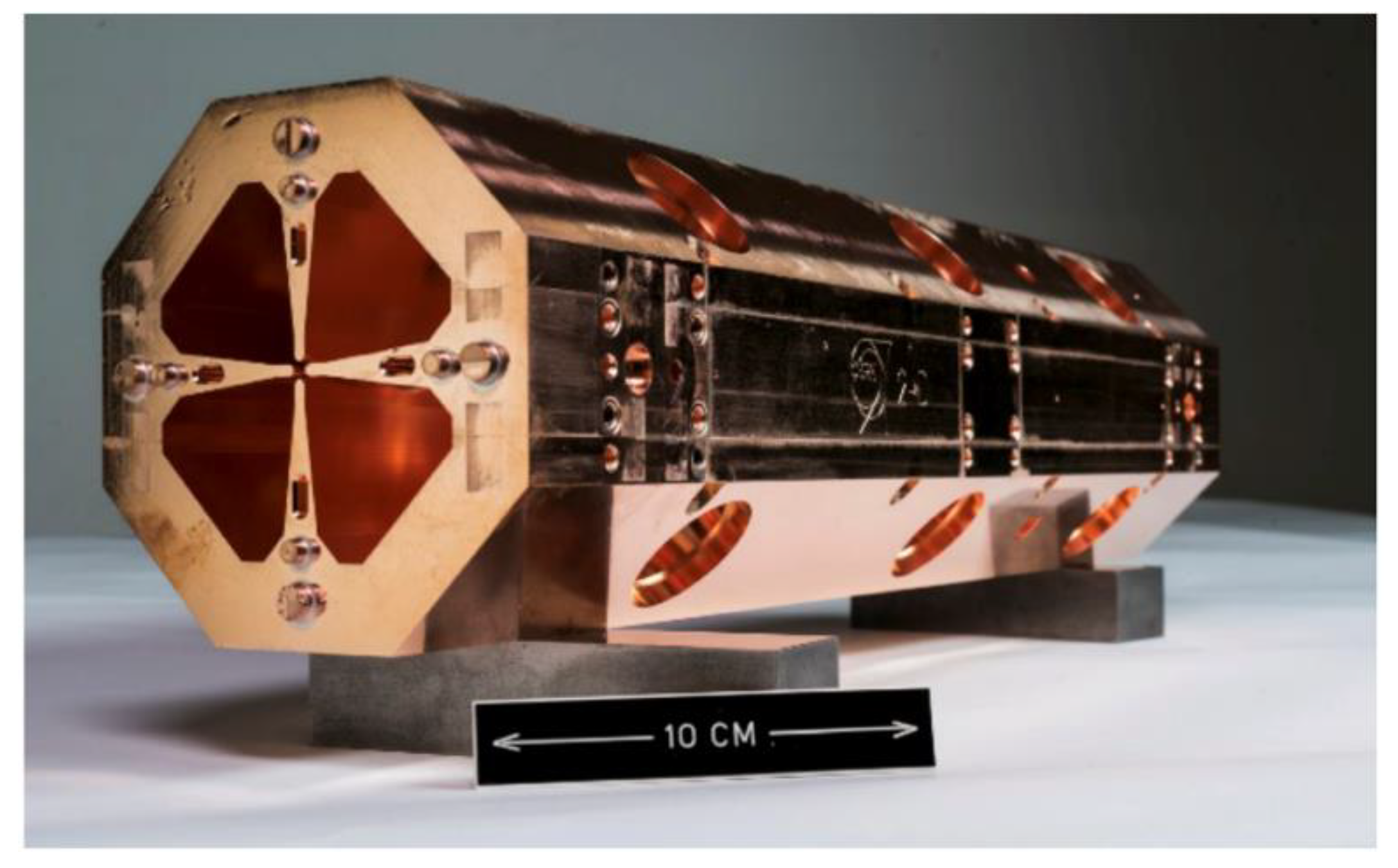
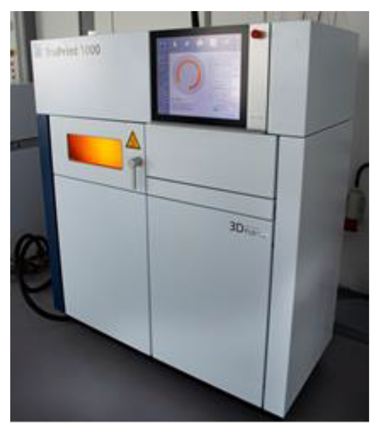
- The pure copper RFQ prototype, using an L-PBF system equipped with a green laser, can be manufactured in a reasonable time—16 h 29 min—with 3267 layers of 30 µm layer thickness.
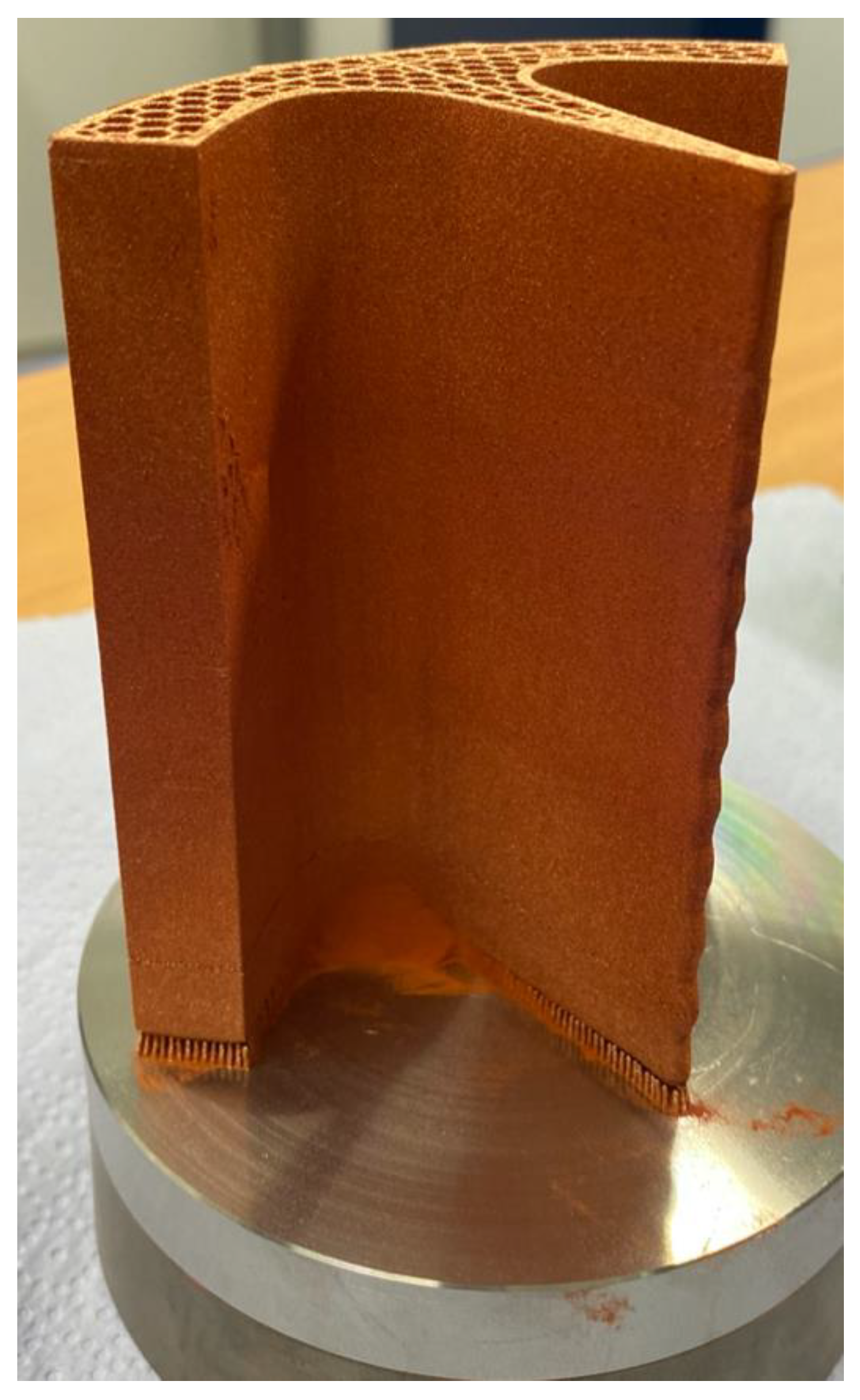
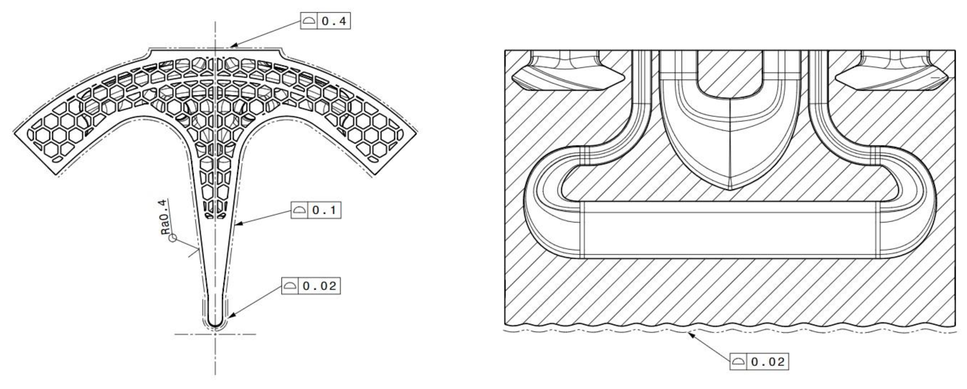
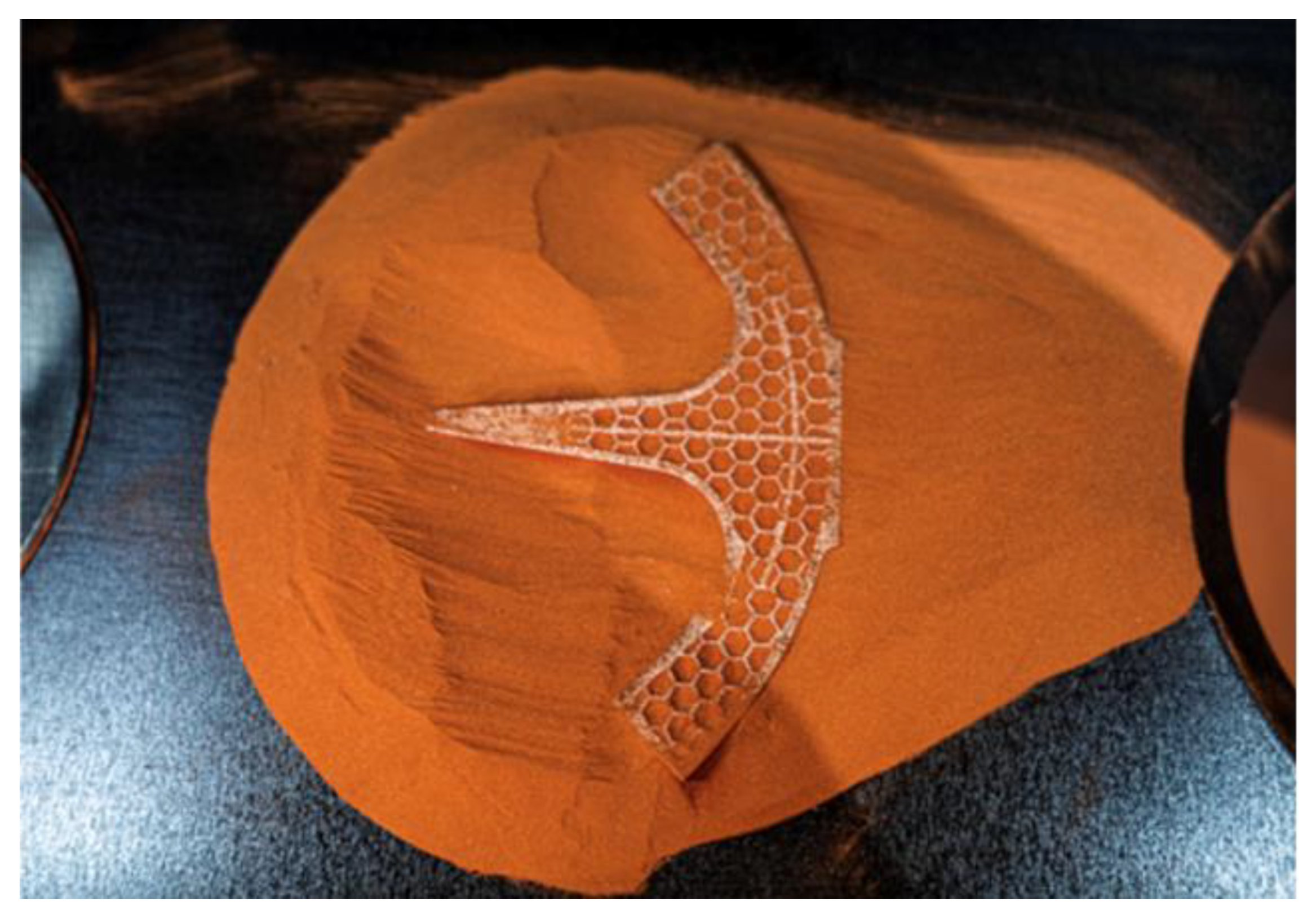
- Most of the external and internal shapes of the RFQ can be successfully optimised. The lightened RFQ structure is feasible by using a honeycomb pattern and by replacing the most massive sections.
- The shape and structure of the RFQ cooling channels can be improved according to the optimum thermal management and flow-dynamics needs—and not dictated by technological restrictions of the conventional manufacturing.
- The honeycomb structure implementation and optimisation of the cooling channels allow for substantial weight reduction—in this case ~37% (~21% and ~16% respectively).
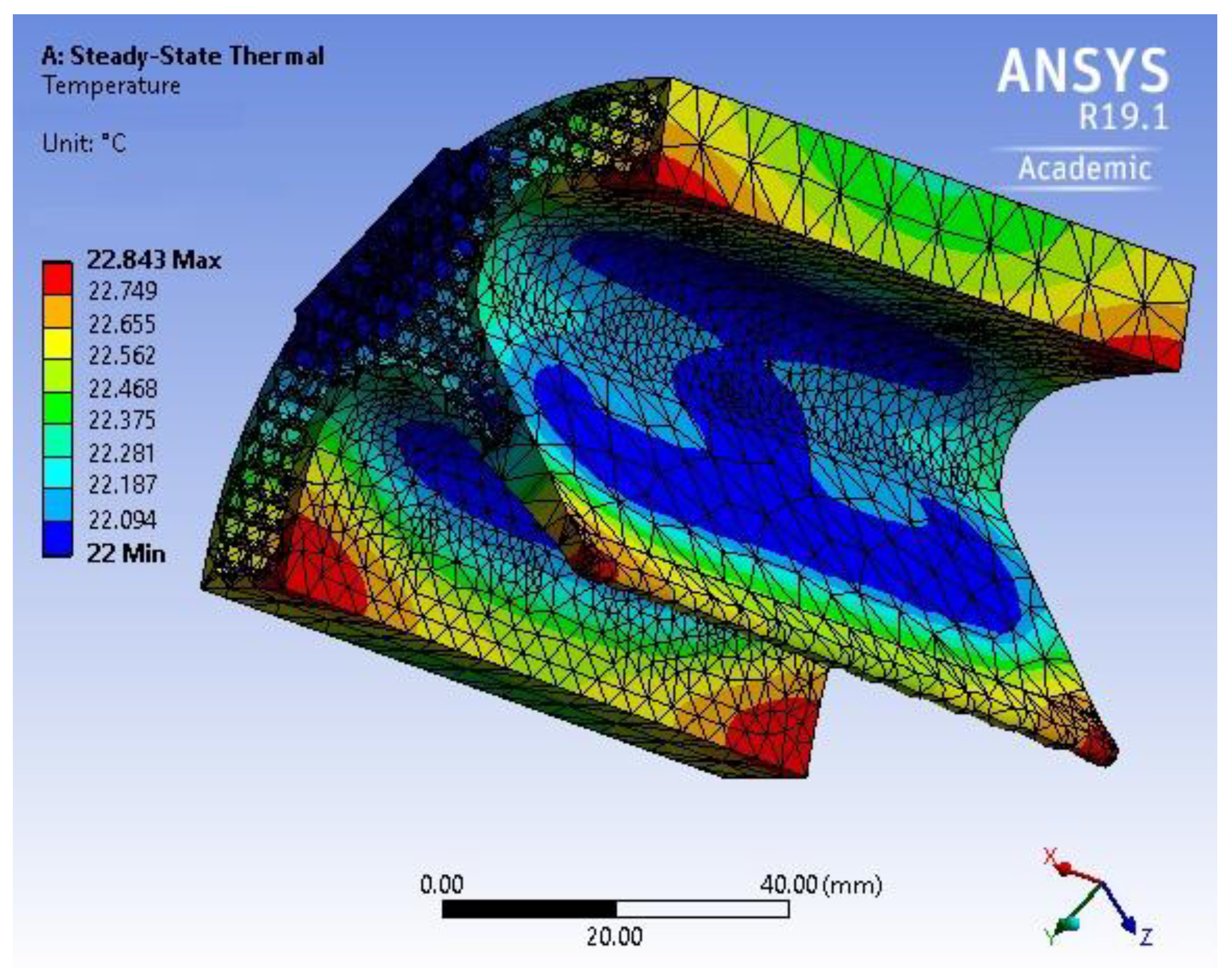
- The steady-state thermal analysis showed that for the operating conditions of the CERN PIXE RFQ, the temperature difference between different sectors remains in the order of ~0.8 °C—thereby not posing any risk for the RFQ’s functionality.
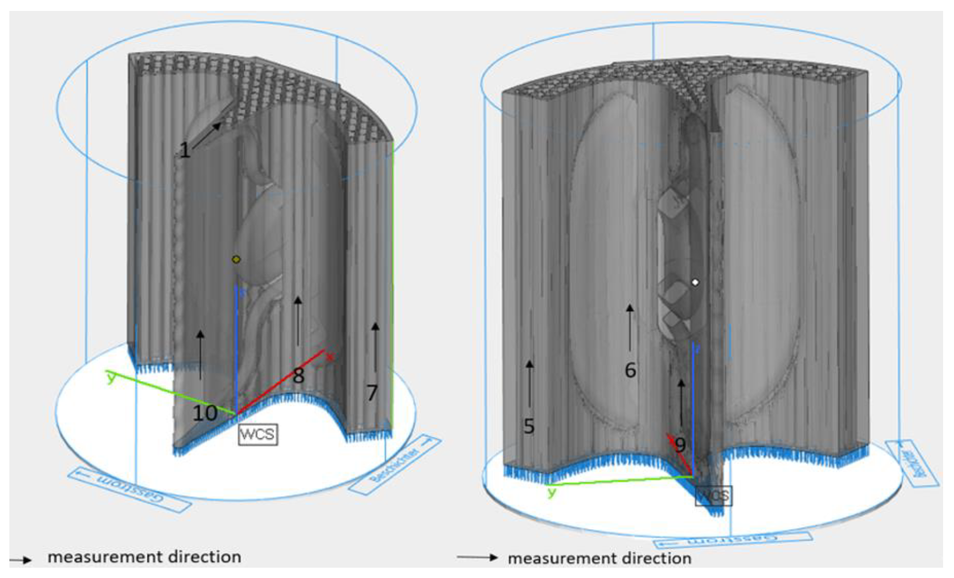
- The surface roughness measurements indicated that the prototype surface roughness quality is still far from the required Ra = 0.4 µm. The surface arithmetical mean roughness average (Ra) was registered as 14.32 µm, and the maximum height of the profile (Rz) as 116.7 µm. However, these results are encouraging, since they were obtained without any adaptation of the AM technological process for better surface roughness outputs.
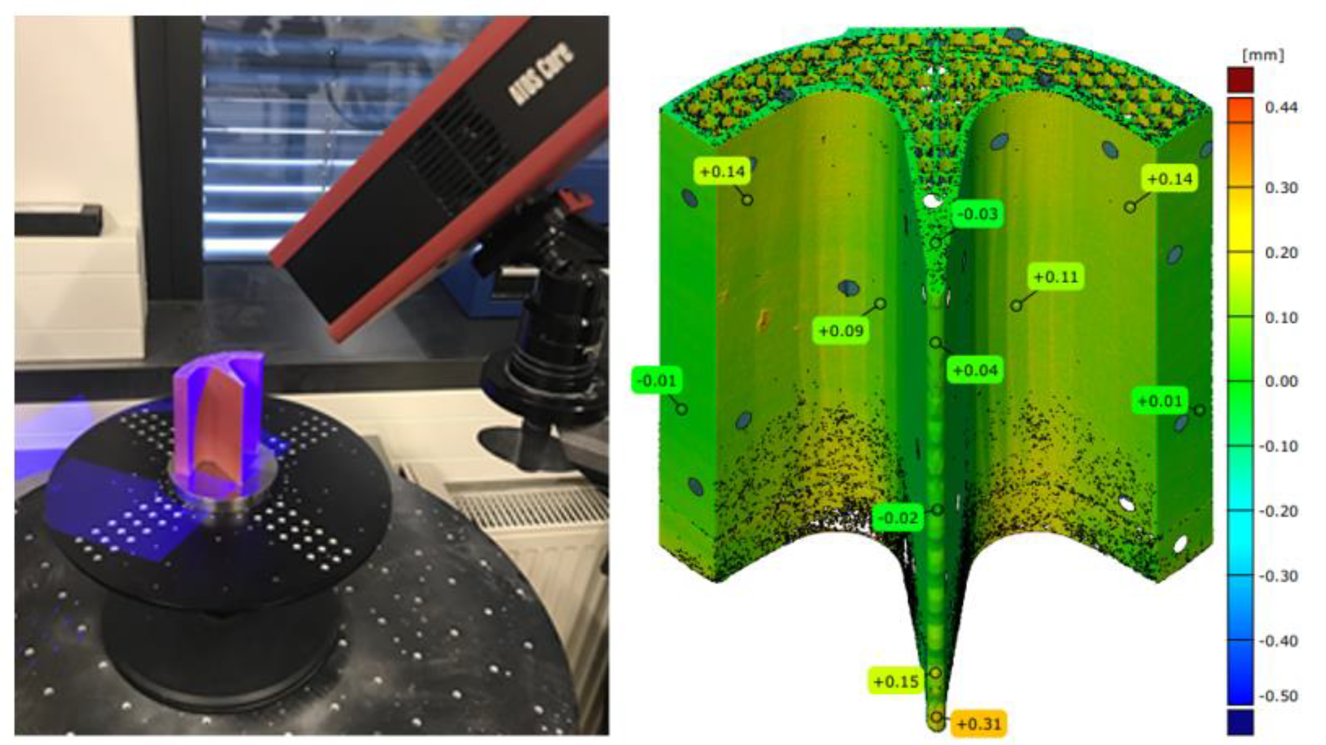
- The geometrical accuracy measurements revealed promising results—with the conventional AM methodology approaching the required precision of 20 µm on the vane tip and fully reaching 100 µm on other surfaces. The largest deviation of 0.31 mm on the vane tip can be attributed to a technological glitch—distortion of the support structures during the build process.
5.1. Lessons Learned
5.2. Lessons for the Future
Author Contributions
Funding
Data Availability Statement
Conflicts of Interest
References
- Lombardi, A. The Radio Frequency Quadrupole (RFQ); CERN: Geneva, Switzerland; Available online: https://cds.cern.ch/record/1005049/files/p201.pdf (accessed on 4 May 2021).
- Lambert, A.; DeMello, A.J.; Hoff, M.D.; Li, D.; Luo, T.; Staples, J.W.; Virostek, S.P.; Andrews, R.; Baffes, C.; Berrutti, P.; et al. High-Intensity Proton RRQ Accelerator Fabrication Status For Pxie. In Proceedings of the IPAC2015, Richmond, VA, USA, 6 May 2015; Available online: https://accelconf.web.cern.ch/ipac2015/papers/wepty045.pdf (accessed on 4 May 2021).
- Rossi, C. High-frequency Compact Rfqs for Medical and Industrial Applications. LINAC 4 RFQ Design, Construction, Commissioning, and Operation. CERN 2018. Available online: https://indico.cern.ch/event/754020/contributions/3123638/attachments/1713693/2763818/L4SpareRFQ_C_Rossi_11092018.pdf (accessed on 21 September 2021).
- Sattonnay, G.; Jenzer, S.; Alves, M.; Bilgen, S.; Bonis, J.; Brisset, F.; Djelali, S.; Gonnin, A.; Guerrier, M.; Grasset, G.; et al. Is It Possible to Use Additive Manufacturing for Accelerator UHV Beam Pipes? In Proceedings of the 10th International Particle Accelerator Conference, Melbourne, Australia, 19–24 May 2019; pp. 2240–2243. [Google Scholar]
- Delerue, N.; Carduner, H.; Gerard, R.L.; Jenzer, S.; Manil, P. Prospects of additive manufacturing for accelerators. In Proceedings of the 10th International Particle Accelerator Conference, Melbourne, Australia, 19–24 May 2019; pp. 4118–4120. [Google Scholar]
- Veness, R.; Andreazza, W.; Gudkov, D.; Miarnau Marin, A.; Samuelsson, S. Metal 3D Additive Machining for in-Vacuum Beam Instrumentation. In Proceedings of the MEDSI’18, Paris, France, 26 June 2018; pp. 121–124. [Google Scholar] [CrossRef]
- Pepato, A. R&D Sullo Sviluppo di Materiali Metallici con la Tecnologia Della Manifattura Additiva Presso il Laboratorio DIAM INFN PD. INFN DIAM 2020. Available online: https://agenda.infn.it/event/21880/contributions/111401/attachments/75741/97112/Presentazione_DIAM_Pepato_28092020.pdf (accessed on 7 June 2021).
- “Innovation Fostering in Accelerator Science and Technology” Project Co-Financed by the European Union Horizon 2020 Research and Innovation Programme (Grant Agreement No 101004730). Available online: https://ifast-project.eu (accessed on 15 October 2021).
- Gruber, S.; Stepien, L.; López, E.; Brueckner, F.; Leyens, C. Physical and Geometrical Properties of Additively Manufactured Pure Copper Samples Using a Green Laser Source. Materials 2021, 14, 3642. [Google Scholar] [CrossRef] [PubMed]
- Wagenblast, P.; Myrell, A.; Thielmann, M.; Scherbaum, T.; Coupek, D. Additive manufacturing with green disk lasers. In Proceedings of the Proc. SPIE 11271, Laser 3D Manufacturing VII, San Francisco, CA, USA, 2 March 2020. [Google Scholar] [CrossRef]
- Lodes, M.A.; Guschlbauer, R.; Körner, C. Process development for the manufacturing of 99.94% pure copper via selective electron beam melting. Mater. Lett. 2015, 143, 298–301. [Google Scholar] [CrossRef]
- Jadhav, S.D.; Goossens, L.R.; Kinds, Y.; van Hooreweder, B.; Vanmeensel, K. Laser-based powder bed fusion additive manufacturing of pure copper. Addit. Manuf. 2021, 42, 101990. [Google Scholar] [CrossRef]
- Jiang, Q.; Zhang, P.; Yu, Z.; Shi, H.; Wu, D.; Yan, H.; Ye, X.; Lu, Q.; Tian, Y. A Review on Additive Manufacturing of Pure Copper. Coatings 2021, 11, 740. [Google Scholar] [CrossRef]
- Leach, R.; Carmignato, S. (Eds.) Precision Additive Metal Manufacturing; CRC Press: Boca Raton, FL, USA, 2020; ISBN 9781138347717. [Google Scholar]
- Vretenar, M.; Dimov, V.A.; Garlasché, M.; Grudiev, A.; Koubek, B.; Lombardi, A.M.; Mathot, S.; Mazur, D.; Montesinos, E.; Timmins, M. High-frequency compact RFQs for medical and industrial applications. In Proceedings of the LINAC2016, East Lansing, East Lansing, MI, USA, 25–30 September 2016; pp. 704–709. Available online: https://cds.cern.ch/record/2304386/files/th1a06.pdf (accessed on 21 September 2021).
- Pommerenke, H.W.; Bencini, V.; Grudiev, A.; Lombardi, A.M.; Mathot, S.; Montesinos, E.; Timmins, M.; Rienen, U.; Vretenar, M. RF design studies on the 750 MHz radio frequency quadrupole linac for proton-induced x-ray emission analysis. Phys. Rev. Accel. Beams 2019, 22, 052003. [Google Scholar] [CrossRef] [Green Version]
- 2020 Update of the European Strategy for Particle Physics. Available online: https://cds.cern.ch/record/2721370/files/CERN-ESU-015-2020%20Update%20European%20Strategy.pdf (accessed on 27 September 2021).
- Torims, T.; Logins, A.; Castellano Rosado, P.; Gutiérrez, S.; Torres, R. The dependence of 3D surface roughness parameters on high-speed milling technological parameters and machining strategy. In Proceedings of the ASME 2014 International Mechanical Engineering Congress and Exposition, Montreal, QC, Canada, 14–20 November 2014. [Google Scholar]
- Logins, A.; Castellano, P.R.; Torims, T.; Gutiérrez, S.C.; Sergejev, F. Experimental analysis of end mill axis inclination and its influence on 3D areal surface texture parameters. Proc. Est. Acad. Sci. 2017, 66, 194–201. [Google Scholar] [CrossRef]


| Requirement | Target Values |
|---|---|
| Geometrical accuracy | 20 µm on vane tip, 100 µm elsewhere |
| Surface roughness | Ra = 0.4 µm for all inner surfaces |
| Porosity, degassing | Vacuum 10−7 mbar |
| Electrical conductivity | 90% IACS 1 |
| Peak electric field on surface | ~40 MV/m |
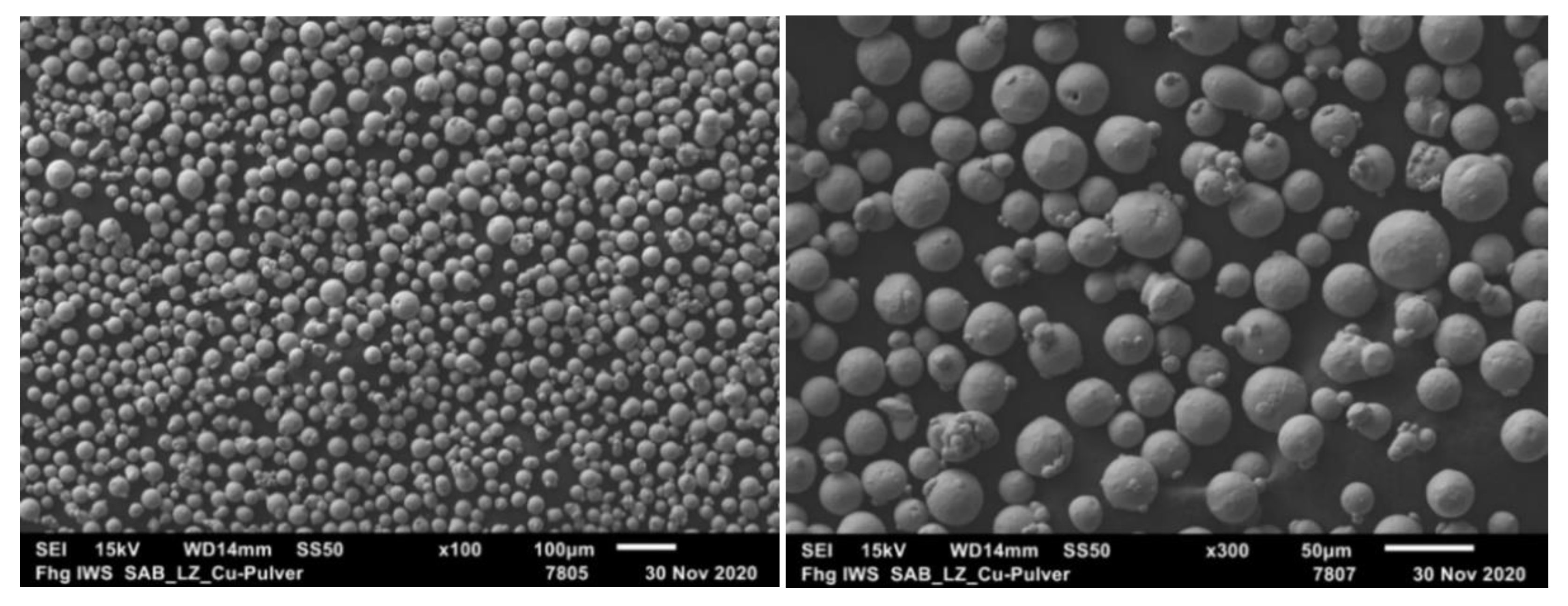
| Powder | D10 in µm | D50 in µm | D90 in µm | Sphericity |
|---|---|---|---|---|
| Cu-ETP(Electrolytic Tough-Pitch: pure copper) | 19.5 | 26.2 | 34.9 | 0.923 |
| Ra (µm) | Rz (µm) | |||||||
|---|---|---|---|---|---|---|---|---|
| Location | Measurement No. | Measurement No. | ||||||
| 1 | 2 | 3 | Mean | 1 | 2 | 3 | Mean | |
| 6 | 10.4 | 12.4 | 12.8 | 11.9 | 84.2 | 89.5 | 85.6 | 86.5 |
| 8 | 15.1 | 15.0 | 15.3 | 15.1 | 148.8 | 138.7 | 143.0 | 143.5 |
| 9 | 13.8 | 14.9 | 13.5 | 14.1 | 117.2 | 123.6 | 104.7 | 115.1 |
| 10 | 13.9 | 14.9 | 14.9 | 14.6 | 117.5 | 134.2 | 103.3 | 118.3 |
Publisher’s Note: MDPI stays neutral with regard to jurisdictional claims in published maps and institutional affiliations. |
© 2021 by the authors. Licensee MDPI, Basel, Switzerland. This article is an open access article distributed under the terms and conditions of the Creative Commons Attribution (CC BY) license (https://creativecommons.org/licenses/by/4.0/).
Share and Cite
Torims, T.; Pikurs, G.; Gruber, S.; Vretenar, M.; Ratkus, A.; Vedani, M.; López, E.; Brückner, F. First Proof-of-Concept Prototype of an Additive Manufactured Radio Frequency Quadrupole. Instruments 2021, 5, 35. https://doi.org/10.3390/instruments5040035
Torims T, Pikurs G, Gruber S, Vretenar M, Ratkus A, Vedani M, López E, Brückner F. First Proof-of-Concept Prototype of an Additive Manufactured Radio Frequency Quadrupole. Instruments. 2021; 5(4):35. https://doi.org/10.3390/instruments5040035
Chicago/Turabian StyleTorims, Toms, Guntis Pikurs, Samira Gruber, Maurizio Vretenar, Andris Ratkus, Maurizio Vedani, Elena López, and Frank Brückner. 2021. "First Proof-of-Concept Prototype of an Additive Manufactured Radio Frequency Quadrupole" Instruments 5, no. 4: 35. https://doi.org/10.3390/instruments5040035