
A Compact Avalanche-Transistor-Based Pulse Generator for Transcranial Infrared Light Stimulation (TILS) Experiments

 , , and
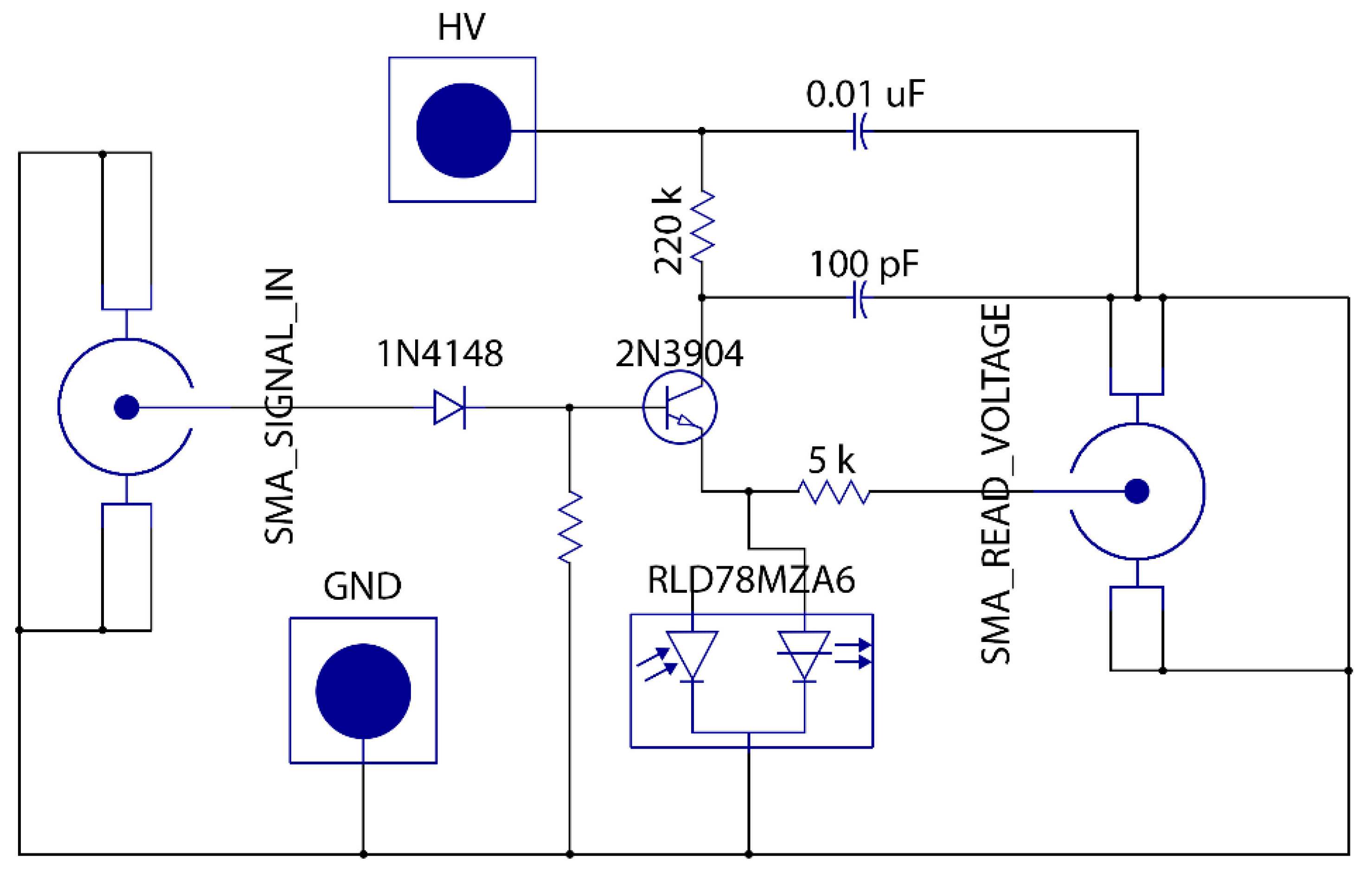
Abstract
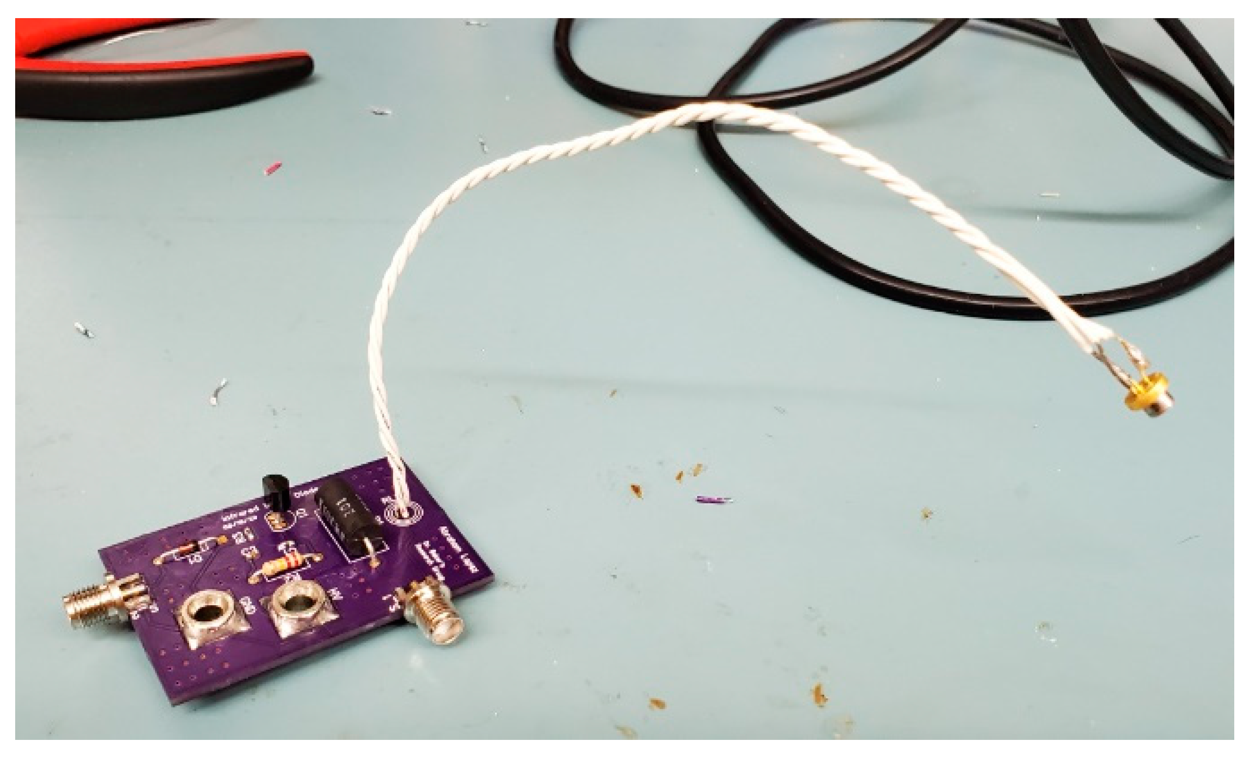
:1. Pulse Generator Design
2. Experimental Methods and Placement of the Laser Diode
2.1. Animals and Surgical Procedures
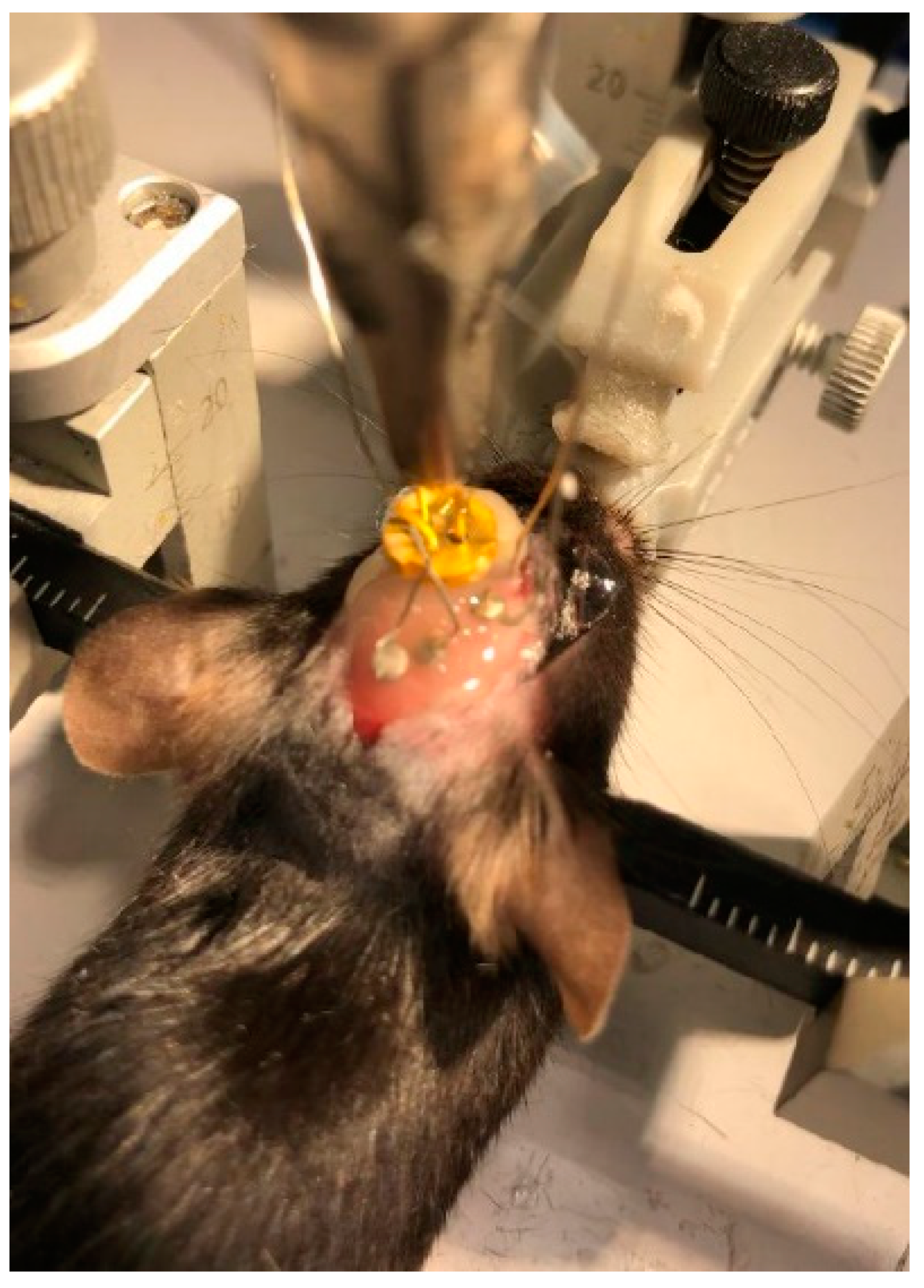
2.2. Laser Diode Placement and Mounting
2.3. Electroencephalogram and Electromyogram Recordings
3. Experimental Results
4. Concluding Remarks
Author Contributions
Funding
Institutional Review Board Statement
Informed Consent Statement
Data Availability Statement
Conflicts of Interest
References
- Baker, R.J. High voltage pulse generation using current mode second breakdown in a bipolar junction transistor. Rev. Sci. Instrum. 1991, 62, 1031–1036. [Google Scholar] [CrossRef]
- Ando, T.; Xuan, W.; Xu, T.; Dai, T.; Sharma, S.K.; Kharkwal, G.B.; Huang, Y.; Wu, Q.; Whalen, M.J.; Sato, S.; et al. Comparison of Therapeutic Effects between Pulsed and Continuous Wave 810-nm Wavelength Laser Irradiation for Traumatic Brain Injury in Mice. PLoS ONE 2011, 6, e26212. [Google Scholar] [CrossRef] [PubMed] [Green Version]
- Naeser, M.A.; Hamblin, M.R. Potential for Transcranial Laser or LED Therapy to Treat Stroke, Traumatic Brain Injury, and Neurodegenerative Disease. Photomed. Laser Surg. 2011, 29, 443–446. [Google Scholar] [CrossRef]
- Wang, X.; Reddy, D.D.; Nalawade, S.S.; Pal, S.; Gonzalez-Lima, F.; Liu, H. Impact of heat on metabolic and hemodynamic changes in transcranial infrared laser stimulation measured by broadband near-infrared spectroscopy. Neurophotonics 2017, 5, 011004. [Google Scholar] [CrossRef]
- Saucedo, C.L.; Courtois, E.C.; Wade, Z.S.; Kelley, M.N.; Kheradbin, N.; Barrett, D.W.; Gonzalez-Lima, F. Transcranial laser stimulation: Mitochondrial and cerebrovascular effects in younger and older healthy adults. Brain Stimul. 2021, 14, 440–449. [Google Scholar] [CrossRef] [PubMed]


Publisher’s Note: MDPI stays neutral with regard to jurisdictional claims in published maps and institutional affiliations. |
© 2022 by the authors. Licensee MDPI, Basel, Switzerland. This article is an open access article distributed under the terms and conditions of the Creative Commons Attribution (CC BY) license (https://creativecommons.org/licenses/by/4.0/).
Share and Cite
Lopez, A.; Strong, H.N.; McGlothen, K.I.; Hines, D.J.; Baker, R.J. A Compact Avalanche-Transistor-Based Pulse Generator for Transcranial Infrared Light Stimulation (TILS) Experiments. Instruments 2022, 6, 20. https://doi.org/10.3390/instruments6030020
Lopez A, Strong HN, McGlothen KI, Hines DJ, Baker RJ. A Compact Avalanche-Transistor-Based Pulse Generator for Transcranial Infrared Light Stimulation (TILS) Experiments. Instruments. 2022; 6(3):20. https://doi.org/10.3390/instruments6030020
Chicago/Turabian StyleLopez, Abraham, Haley N. Strong, Kendra I. McGlothen, Dustin J. Hines, and R. Jacob Baker. 2022. "A Compact Avalanche-Transistor-Based Pulse Generator for Transcranial Infrared Light Stimulation (TILS) Experiments" Instruments 6, no. 3: 20. https://doi.org/10.3390/instruments6030020