
A Compact Particle Detector for Space-Based Applications: Development of a Low-Energy Module (LEM) for the NUSES Space Mission

 , , and
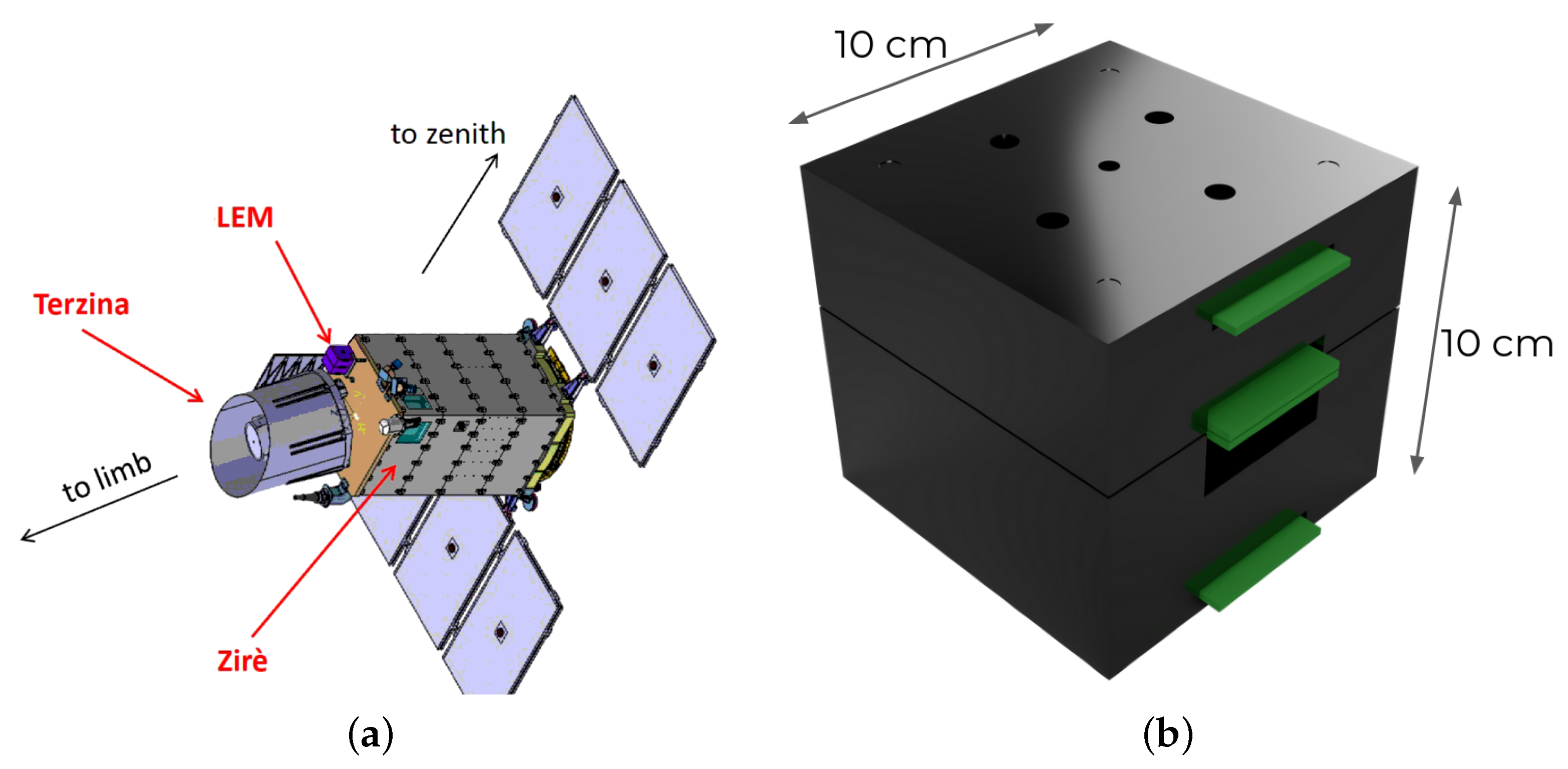
Abstract
:1. Introduction: The NUSES Space Mission
2. The Need for a Low Energy Module
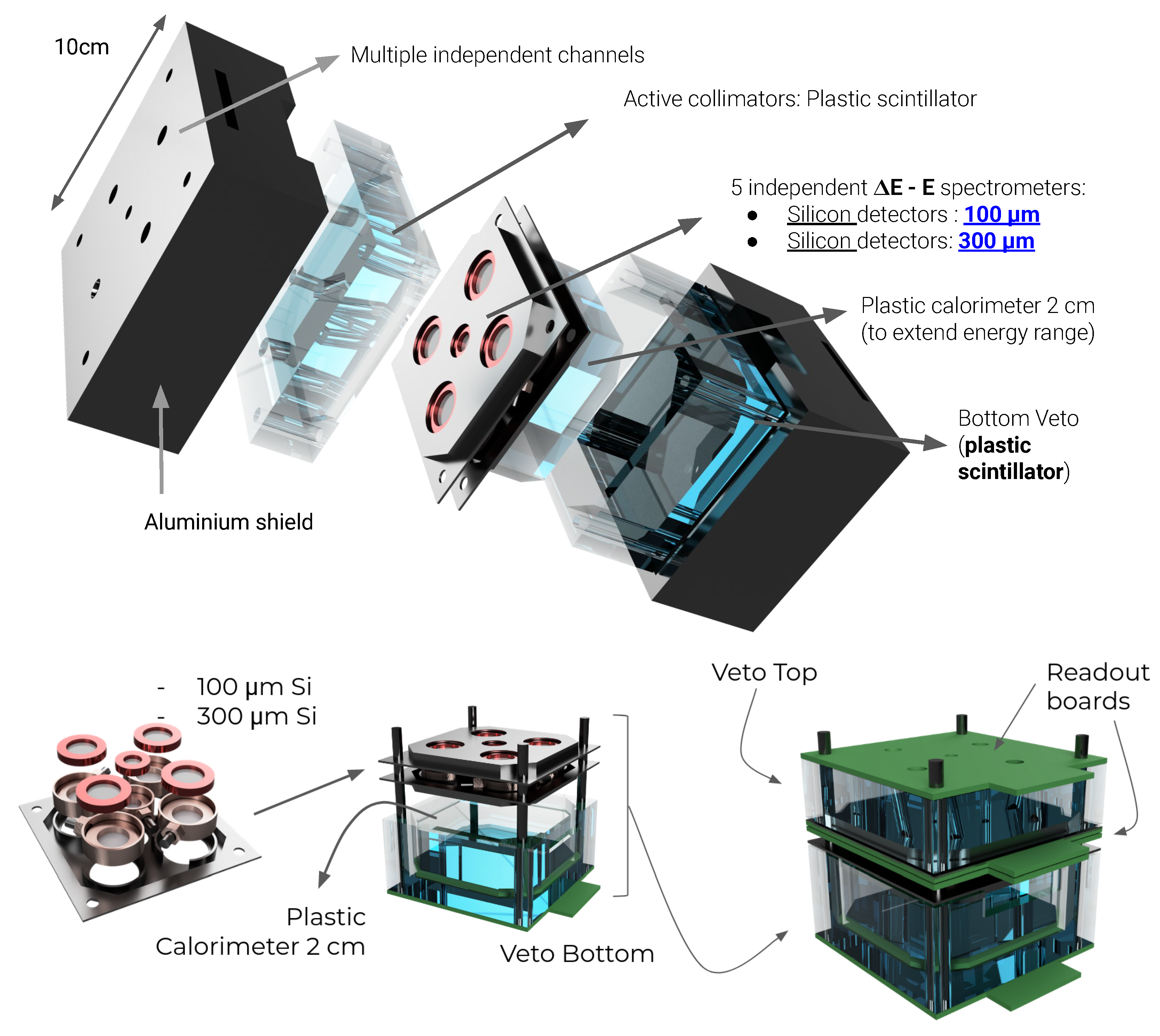
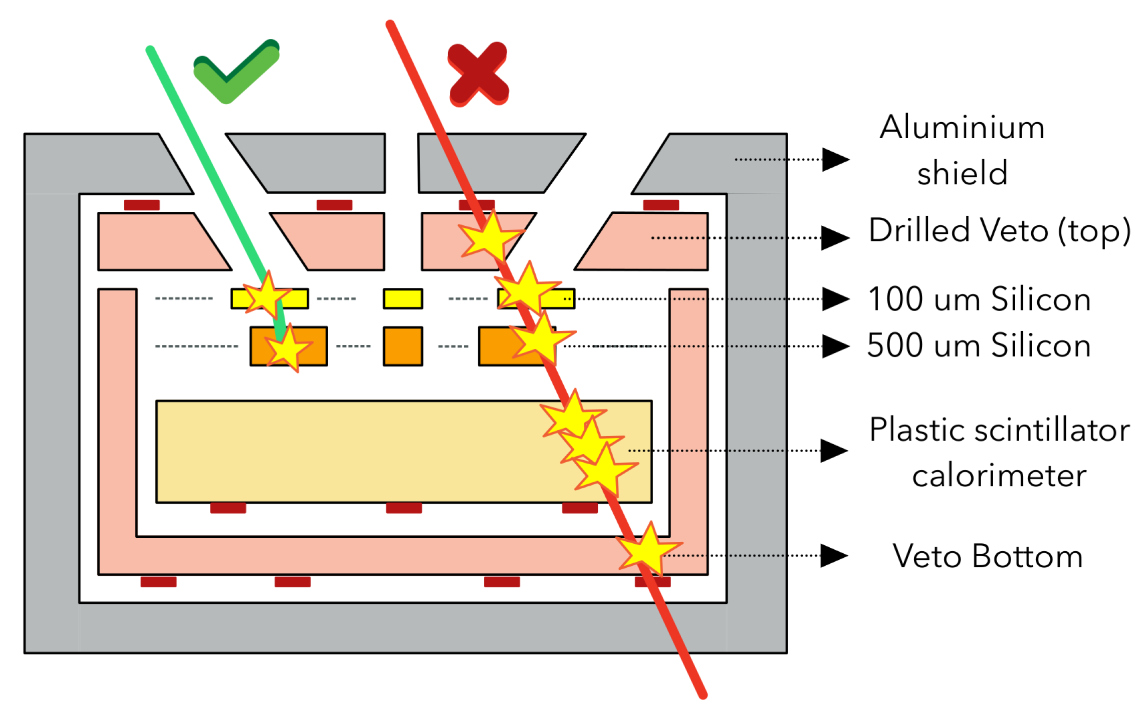
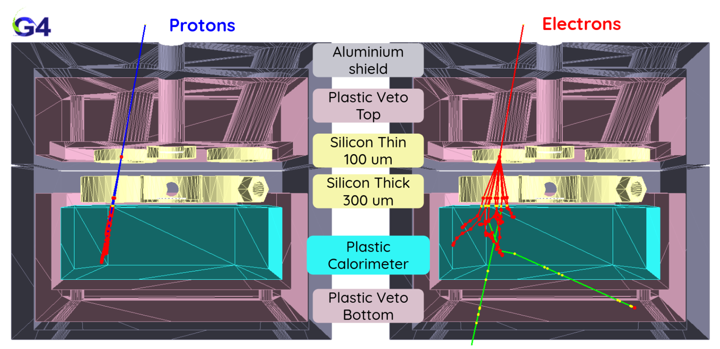
3. Geometry and Detection Concept of the LEM
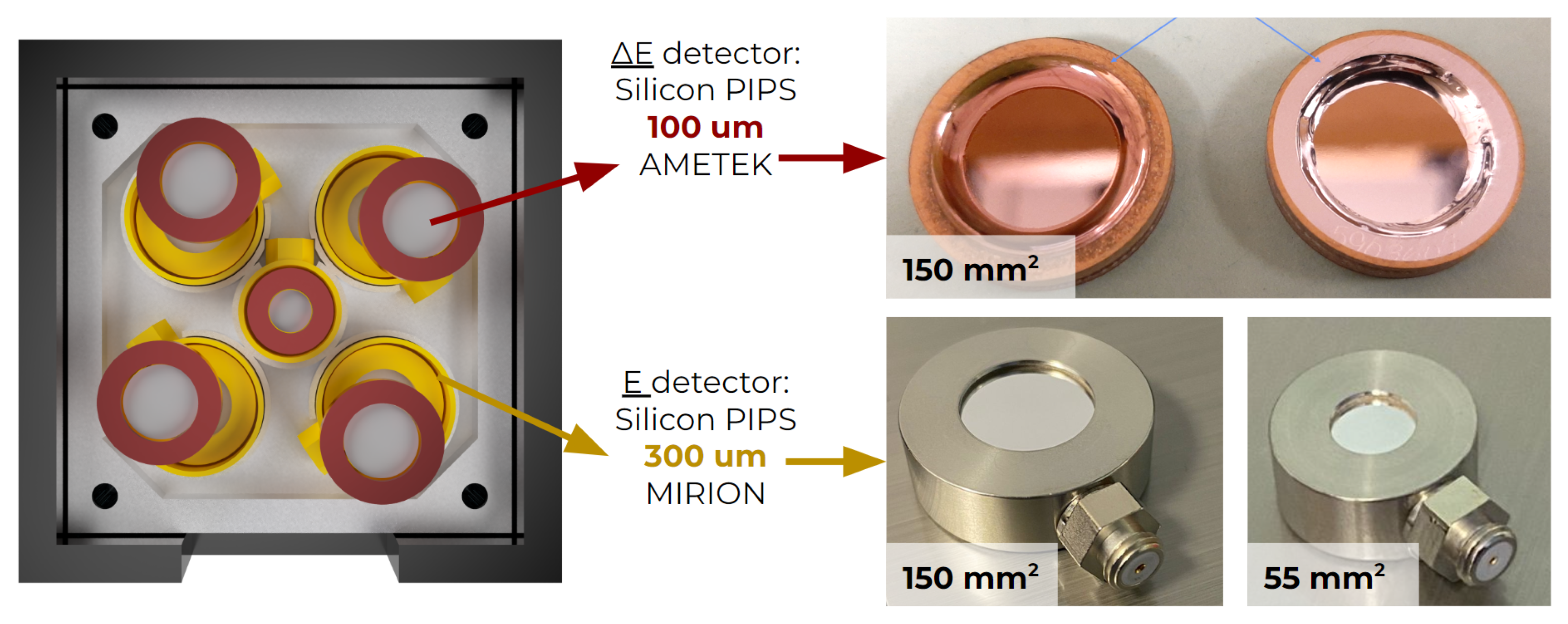
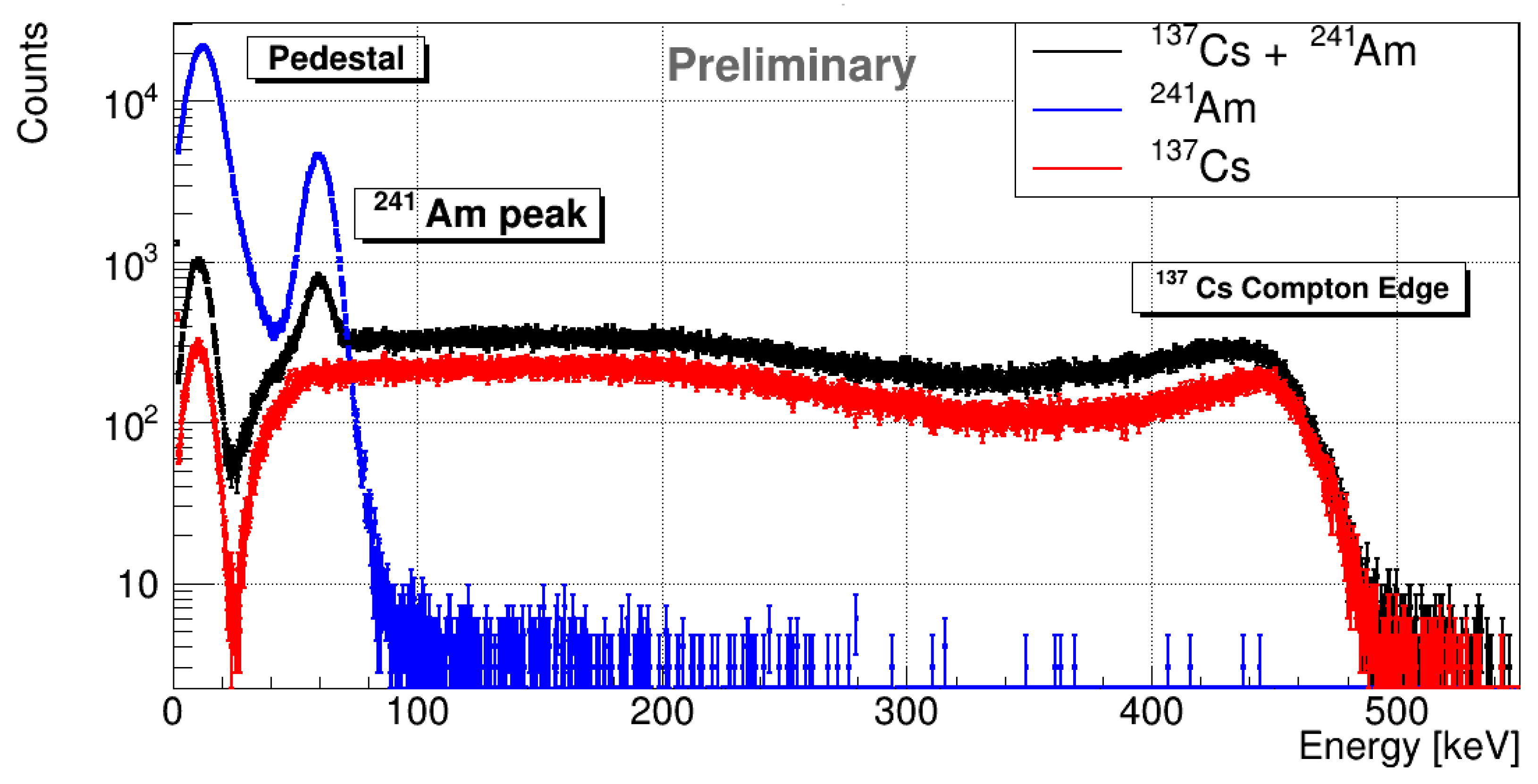
4. Preliminary Test on PIPS Sensors
5. Conclusions
Supplementary Materials
Author Contributions
Funding
Institutional Review Board Statement
Informed Consent Statement
Data Availability Statement
Conflicts of Interest
Abbreviations
| ACD | Anti-Coincidence Detector |
| CSA | Charge Sensitive Amplifier |
| EAS | Extensive Air Showers |
| FOV | Field Of View |
| GDML | Geometry Description Markup Language |
| GEANT4 | GEometry ANd Tracking 4 |
| GRB | Gamma-Ray Burst |
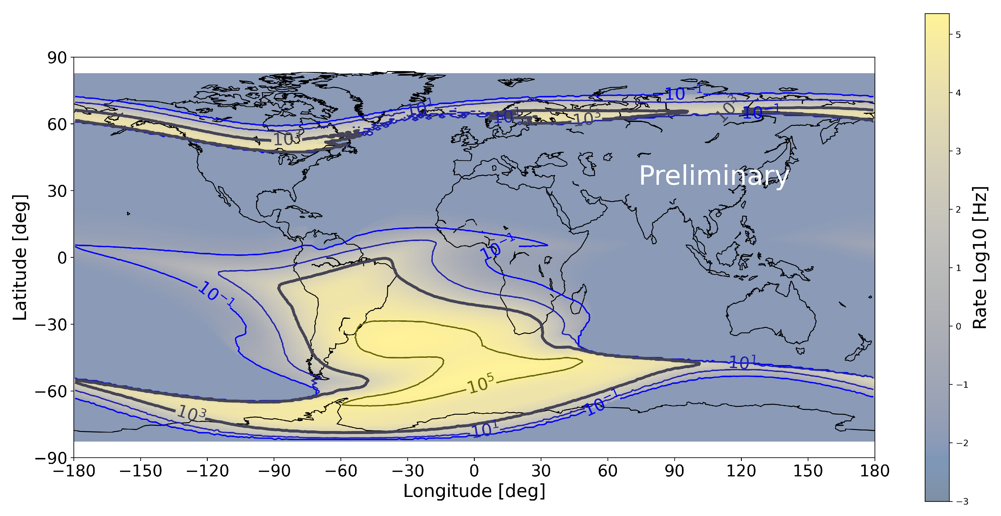
| IRENE | International Radiation Environment Near Earth |
| LAIM | Lithosphere Atmosphere Ionosphere Magnetosphere |
| LEM | Low-Energy Module |
| LEO | Low Earth Orbit |
| LYSO | Lutetium–Yttrium OxyorthoSilicate |
| MILC | Magnetosphere ionosphere lithosphere coupling |
| MIP | Minimum Ionizing Particle |
| MPV | Most Probable Value |
| NUSES | NeUtrino and Seismic Electromagnetic Signals |
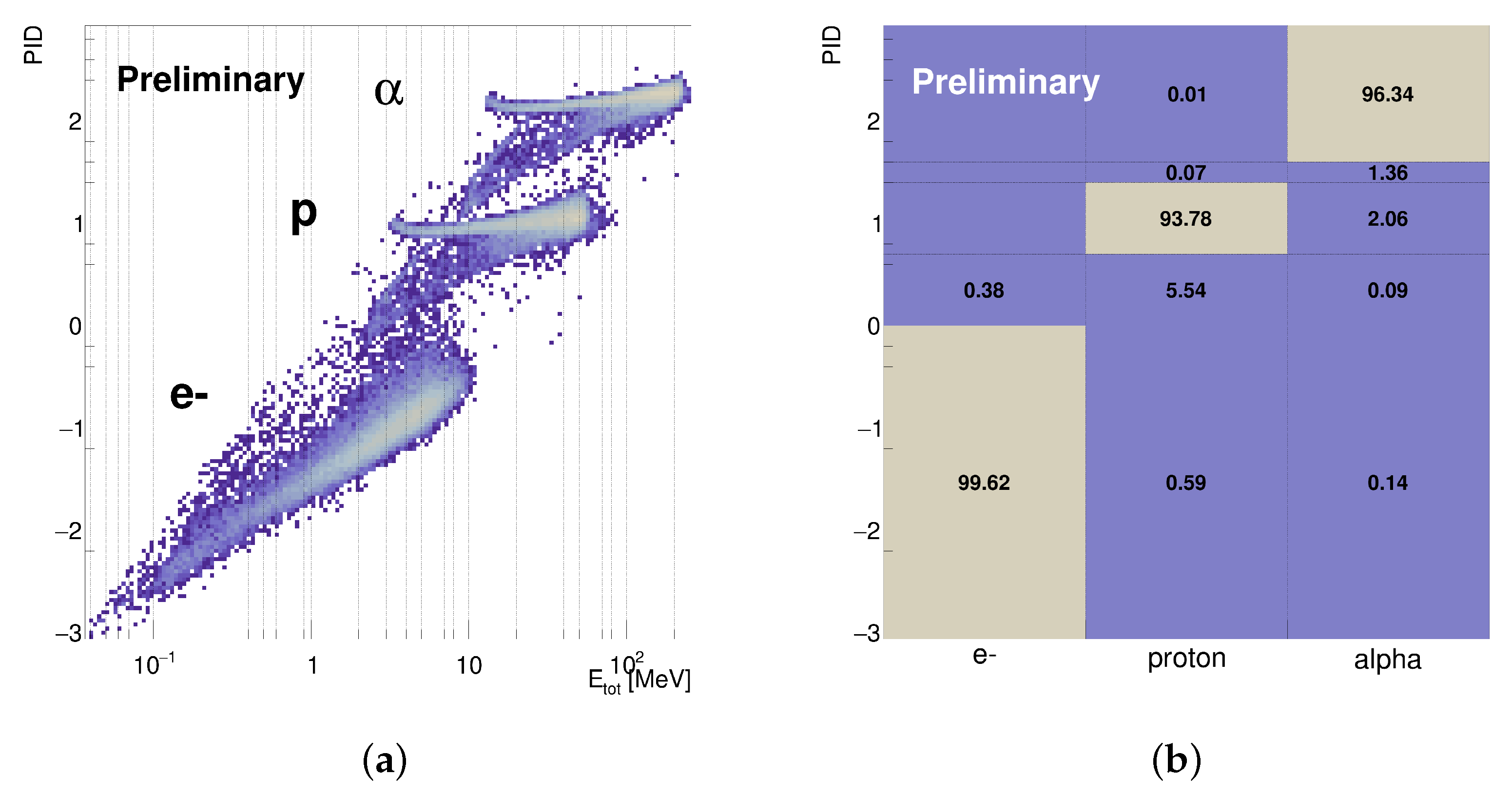
| PID | Particle Identification |
| PIPS | Passivated Implanted Planar Silicon |
| SAA | South Atlantic Anomaly |
| TGF | Terrestrial Gamma-ray Flash |
| UAS | Upgoing Air Showers |
| VAB | Van Allen Belt |
References
- Burmistrov, L. Terzina on board NUSES: A pathfinder for EAS Cherenkov Light Detection from space. Proc. Eur. Phys. J. Web Conf. 2023, 283, 06006. [Google Scholar] [CrossRef]
- Aloisio, R.; Burmistrov, L.; Heller, M.; Montaruli, T.; Trimarelli, C. The Terzina instrument onboard the NUSES space mission. Proc. Sci. 2023, 444, 391. [Google Scholar] [CrossRef]
- De Mitri, I.; Di Santo, M. The NUSES space mission. In Proceedings of the Journal of Physics: Conference Series; IOP Publishing: Bristol, UK, 2023; Volume 2429, p. 012007. [Google Scholar] [CrossRef]
- Di Giovanni, A.; Di Santo, M. The NUSES space mission. Proc. Sci. 2022, 414, 354. [Google Scholar] [CrossRef]
- Di Santo, M.; Di Giovanni, A. The NUSES space mission. Proc. Sci. 2023, 423, 143. [Google Scholar] [CrossRef]
- Mazziotta, M.N.; Altomare, C.; Bissaldi, E.; De Gaetano, S.; De Robertis, G.; Dipinto, P.; Di Venere, L.; Franco, M.; Fusco, P.; Gargano, F.; et al. A light tracker based on scintillating fibers with SiPM readout. Nucl. Instrum. Methods Phys. Res. Sect. A Accel. Spectrom. Detect. Assoc. Equip. 2022, 1039, 167040. [Google Scholar] [CrossRef]
- Mazziotta, M.N.; Pillera, R. The light tracker based on scintillating fibers with SiPM readout of the Zire instrument on board the NUSES space mission. In Proceedings of the 38th International Cosmic Ray Conference—PoS(ICRC2023), Nagoya, Japan, 26 July–3 August 2023. [Google Scholar] [CrossRef]
- Olinto, A.V.; Krizmanic, J.; Adams, J.; Aloisio, R.; Anchordoqui, L.; Anzalone, A.; Bagheri, M.; Barghini, D.; Battisti, M.; Bergman, D.; et al. The POEMMA (probe of extreme multi-messenger astrophysics) observatory. J. Cosmol. Astropart. Phys. 2021, 2021, 7. [Google Scholar] [CrossRef]
- Olinto, A.; Adams, J.; Aloisio, R.; Anchordoqui, L.; Bergman, D.; Bertaina, M.; Bertone, P.; Christl, M.; Csorna, S.; Eser, J.; et al. POEMMA: Probe Of Extreme Multi-Messenger Astrophysics. In Proceedings of the 35th International Cosmic Ray Conference (ICRC2017), Busan, Republic of Korea, 12–20 July 2017; Volume 301, p. 542. [Google Scholar] [CrossRef]
- Denton, P.B.; Kini, Y. Ultrahigh-energy tau neutrino cross sections with GRAND and POEMMA. Phys. Rev. D 2020, 102, 123019. [Google Scholar] [CrossRef]
- Krizmanic, J. POEMMA: Probe of extreme multi-messenger astrophysics. In Proceedings of the EPJ Web of Conferences; EDP Sciences: Les Ulis, France, 2019; Volume 210, p. 06008. [Google Scholar] [CrossRef]
- Kahler, S. Solar flares and coronal mass ejections. Annu. Rev. Astron. Astrophys. 1992, 30, 113–141. [Google Scholar] [CrossRef]
- Fishman, G.J.; Meegan, C.A. Gamma-ray bursts. Annu. Rev. Astron. Astrophys. 1995, 33, 415–458. [Google Scholar] [CrossRef]
- Piran, T. The physics of gamma-ray bursts. Rev. Mod. Phys. 2005, 76, 1143. [Google Scholar] [CrossRef]
- D’Angelo, G.; Piersanti, M.; Battiston, R.; Bertello, I.; Carbone, V.; Cicone, A.; Diego, P.; Papini, E.; Parmentier, A.; Picozza, P.; et al. Haiti Earthquake (Mw 7.2): Magnetospheric–Ionospheric–Lithospheric Coupling during and after the Main Shock on 14 August 2021. Remote Sens. 2022, 14, 5340. [Google Scholar] [CrossRef]
- Battiston, R.; Vitale, V. First evidence for correlations between electron fluxes measured by NOAA-POES satellites and large seismic events. Nucl. Phys. B-Proc. Suppl. 2013, 243, 249–257. [Google Scholar] [CrossRef]
- Li, X.; Xu, Y.; An, Z.; Liang, X.; Wang, P.; Zhao, X.; Wang, H.; Lu, H.; Ma, Y.; Shen, X.; et al. The high-energy particle package onboard CSES. Radiat. Detect. Technol. Methods 2019, 3, 1–11. [Google Scholar] [CrossRef]
- Scarduelli, V.; Gasques, L.; Chamon, L.; Lépine-Szily, A. A method to optimize mass discrimination of particles identified in ΔE-E silicon surface barrier detector systems. Eur. Phys. J. A 2020, 56, 24. [Google Scholar] [CrossRef]
- Evensen, L.; Westgaard, T.; Avdeichikov, V.; Carlen, L.; Jakobsson, B.; Murin, Y.; Martensson, J.; Oskarsson, A.; Siwek, A.; Whitlow, H.; et al. Thin detectors for the CHICSi/spl Delta/EE telescope. IEEE Trans. Nucl. Sci. 1997, 44, 629–634. [Google Scholar] [CrossRef]
- Carboni, S.; Barlini, S.; Bardelli, L.; Le Neindre, N.; Bini, M.; Borderie, B.; Bougault, R.; Casini, G.; Edelbruck, P.; Olmi, A.; et al. Particle identification using the ΔE–E technique and pulse shape discrimination with the silicon detectors of the FAZIA project. Nucl. Instrum. Methods Phys. Res. Sect. A Accel. Spectrom. Detect. Assoc. Equip. 2012, 664, 251–263. [Google Scholar] [CrossRef]
- Alonso, M.F.; Mitri, I.D. The Zire experiment on board the NUSES space mission. In Proceedings of the 38th International Cosmic Ray Conference—PoS(ICRC2023), Nagoya, Japan, 26 July–3 August 2023. [Google Scholar] [CrossRef]
- Agostinelli, S.; Allison, J.; Amako, K.a.; Apostolakis, J.; Araujo, H.; Arce, P.; Asai, M.; Axen, D.; Banerjee, S.; Barrand, G.; et al. GEANT4—A simulation toolkit. Nucl. Instrum. Methods Phys. Res. Sect. A Accel. Spectr. Detect. Assoc. Equip. 2003, 506, 250–303. [Google Scholar] [CrossRef]
- Chytracek, R.; McCormick, J.; Pokorski, W.; Santin, G. Geometry description markup language for physics simulation and analysis applications. IEEE Trans. Nucl. Sci. 2006, 53, 2892–2896. [Google Scholar] [CrossRef]
- Sloan, K.; Hindi, M.; luzpaz; lambdam94; Lei, Z.; Dmochowski, J. JakubDmochowski. KeithSloan/GDML: New Release for FreeCAD, v. 0.20; Zenodo: Geneva, Switzerland, 2022. [Google Scholar] [CrossRef]
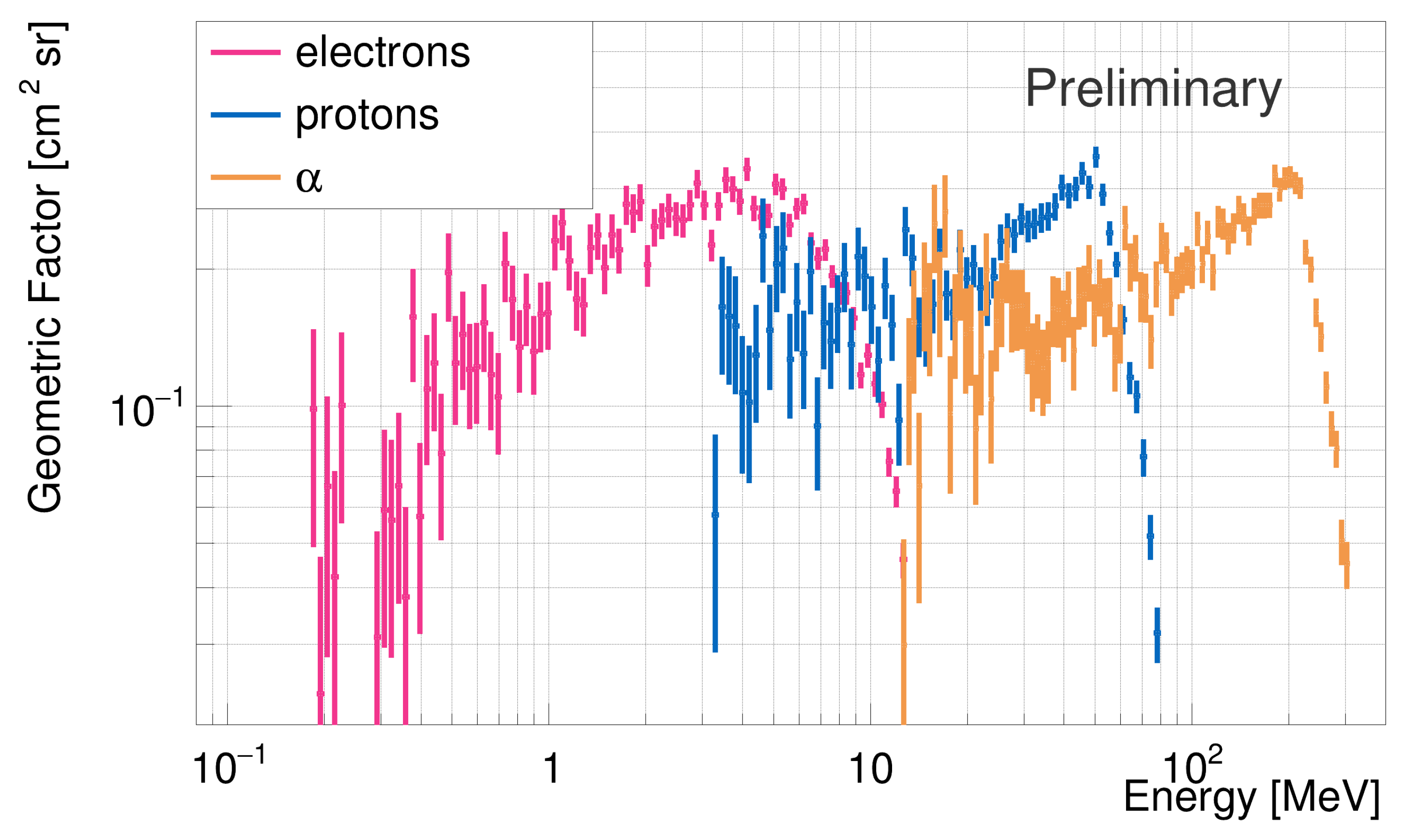
- Sullivan, J. Geometric factor and directional response of single and multi-element particle telescopes. Nucl. Instr. Methods 1971, 95, 5–11. [Google Scholar] [CrossRef]
- Ginet, G.P.; O’Brien, T.P.; Huston, S.L.; Johnston, W.R.; Guild, T.B.; Friedel, C.D.; Roth, C.J.; Whelan, P.; Quinn, R.A.; Madden, D.; et al. AE9, AP9 and SPM: New Models for Specifying the Trapped Energetic Particle and Space Plasma Environment. Space Sci. Rev. 2013, 179, 579–615. [Google Scholar] [CrossRef]
- ORTEC/AMETEK. Si Charged Particle Radiation Detectors for Research Applications. Available online: https://www.ortec-online.com/products/radiation-detectors/silicon-charged-particle-radiation-detectors/si-charged-particle-radiation-detectors-for-research-applications (accessed on 11 October 2023).
- Technologies, M. PIPS Detectors. Available online: https://mirionprodstorage.blob.core.windows.net/prod-20220822/cms4_mirion/files/pdf/spec-sheets/c39313_passivated_pips_super_spec_1.pdf (accessed on 11 October 2023).


Disclaimer/Publisher’s Note: The statements, opinions and data contained in all publications are solely those of the individual author(s) and contributor(s) and not of MDPI and/or the editor(s). MDPI and/or the editor(s) disclaim responsibility for any injury to people or property resulting from any ideas, methods, instructions or products referred to in the content. |
© 2023 by the authors. Licensee MDPI, Basel, Switzerland. This article is an open access article distributed under the terms and conditions of the Creative Commons Attribution (CC BY) license (https://creativecommons.org/licenses/by/4.0/).
Share and Cite
Nicolaidis, R.; Nozzoli, F.; Pepponi, G.; on behalf of the NUSES Collaboration. A Compact Particle Detector for Space-Based Applications: Development of a Low-Energy Module (LEM) for the NUSES Space Mission. Instruments 2023, 7, 40. https://doi.org/10.3390/instruments7040040
Nicolaidis R, Nozzoli F, Pepponi G, on behalf of the NUSES Collaboration. A Compact Particle Detector for Space-Based Applications: Development of a Low-Energy Module (LEM) for the NUSES Space Mission. Instruments. 2023; 7(4):40. https://doi.org/10.3390/instruments7040040
Chicago/Turabian StyleNicolaidis, Riccardo, Francesco Nozzoli, Giancarlo Pepponi, and on behalf of the NUSES Collaboration. 2023. "A Compact Particle Detector for Space-Based Applications: Development of a Low-Energy Module (LEM) for the NUSES Space Mission" Instruments 7, no. 4: 40. https://doi.org/10.3390/instruments7040040