Communication

FAST Low-Energy Beamline Studies: Toward High-Peak 5D Brightness Beams for FAST-GREENS

1
Department of Physics and Astronomy, University of California, Los Angeles, Los Angeles, CA 90095, USA
2
Fermi National Accelerator Laboratory, Batavia, IL 60510, USA
3
RadiaSoft, Boulder, CO 80301, USA
4
RadiaBeam Technologies, Santa Monica, CA 90404, USA
*
Author to whom correspondence should be addressed.
Instruments 2023, 7(4), 42; https://doi.org/10.3390/instruments7040042
Submission received: 30 September 2023 / Revised: 6 November 2023 / Accepted: 9 November 2023 / Published: 17 November 2023

Abstract

:
The FAST beamline is the injector for the planned Gamma-Ray Electron ENhanced Source (GREENS) program, which aims to achieve the demonstration and first application of a high-efficiency, high-average-power free-electron laser at 515 nm. FAST-GREENS requires high 5D peak brightness; transverse normalized projected emittances of 3 mm-mrad and a peak current of 600 A are the minimum beam requirements for the FEL to reach the 10% efficiency goal. In this work, studies of the low-energy section of the FAST beamline are presented toward these ends, including preliminary measurements of beam compression and beam emittance. An effort toward developing a high-fidelity simulation model that could be later optimized for FAST-GREENS is presented.

1. Introduction

The Fermilab Accelerator Science and Technology (FAST) facility is host to several current and proposed projects of notable scientific merit. The FAST injector provides beams for the Integrable Optics Test Accelerator (IOTA) [1] and the under-construction FAST Gamma-Ray Electron Enhanced Source (GREENS) [2], and FAST will host upcoming photocathode studies in a high-gradient photoinjector proposed by the Center for Bright Beams.
FAST-GREENS is a high-efficiency free-electron laser (FEL) experiment initially aimed at demonstrating the Tapering Enhanced Stimulated Superradiant Amplification at a short radiation wavelength [3,4,5]. The high average power of 515 nm radiation can then be redirected against the high-repetition-rate electron bunches from the FAST linac to generate copious amounts of circularly polarized gamma-rays [6]. The requirements for peak 5D beam brightness from the injector are particularly demanding. To these ends, FAST-GREENS will require the FAST injector to run near the boundary of capability on the Pareto front of beam charge vs. transverse emittance. Indeed, the nominal requirements of 3 mm-mrad emittance in each dimension, along with a peak current of 600 A, will require the careful optimization of the upstream injector parameters on an offline model.
This article reports on the development of a high-fidelity model of FAST for optimization toward high-peak 5D beam brightness for FAST-GREENS. Additionally, the proposed work to deduce photocathode properties from solenoid scans at FAST will benefit greatly from such a model, as such studies require a model to invert/optimize (e.g., [7,8,9]).

2. Materials and Methods

The FAST beam line (shown in Figure 1) starts with the gun, of similar type to the DESY-PITZ gun [10,11]. The 1054 nm output from a fiber laser is frequency-quadrupled and is shone onto a Cs 2 Te photocathode to produce photoelectrons [1,12], which are accelerated in the 1.3 GHz, 1.5-cell cavity. This is in turn followed by an emittance compensation solenoid, with adjustable position. The bucking solenoid directly upstream of the gun is generally set to produce a magnetic field in the opposite direction of the main solenoid at a magnitude such that the field at the photocathode is zero, so that the beam is born with zero angular momentum. The gun has an INFN-style load lock system [13] that allows for the exchange of photocathodes. Two TESLA cavities [14] (CC1 and CC2 in Figure 1) are used to accelerate the beam to 35–50 MeV in nominal cases. A series of quadrupoles are used to manipulate the beam transversely. The quadrupoles are followed by a chicane that is used to compress the beam. The chicane starts with D114 in Figure 1. The dipoles in the chicane are set to bend the beam 22.5 , which gives a nominal R 56 of −0.18 m. The chicane can also be bypassed and the beam can be directed from Q113 to Q118, the start of a quadrupole triplet. Following B122, the beam energy can be measured on the beam dump line.
As mentioned above, one of the primary goals of this study is to provide a model for the optimization of compression in the chicane at beam energies below 40 MeV. At these levels, in a chicane, the beam emittance will be diluted by space charge as well as coherent synchrotron radiation (CSR) effects, which must be modeled properly [15,16]. To these ends, the General Particle Tracer (GPT) [17] has been shown to be a good choice to model 3D CSR effects [18]. As such, GPT was chosen as the physics model to use in this effort.
There are numerous free parameters for the model. Table 1 lists these parameters and the data taken to fit them.

3. Results

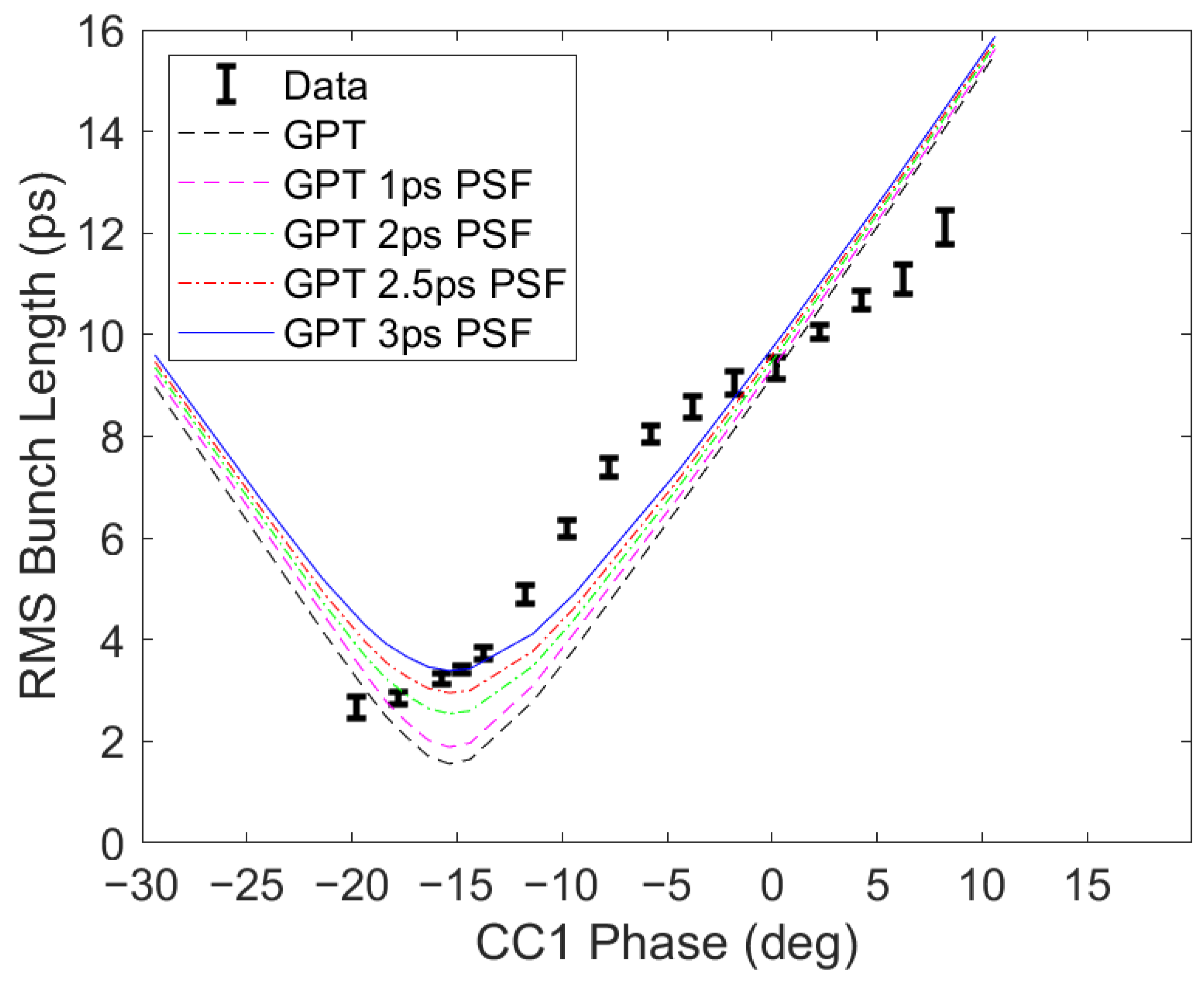
3.1. Longitudinal Dynamics

In order to benchmark longitudinal beam dynamics, two tests were performed: a gun phase scan at X101 and a streak camera measurement at X121 (see Figure 1), approximately 17.4 m downstream of the photocathode. Both will be described below.
For the first test, the gun phase was changed in 0.2-degree intervals and the extracted charge was measured at the exit of the gun. The time it takes for the beam to be extracted from the cathode can be measured from this scan. Neglecting the Schottky effect, the measured charge should start as soon as the RF phase is such that the field accelerates the head of the bunch downstream. As the phase is increased, more of the bunch experiences an accelerating field, until the full bunch does, at which point the full beam charge is measured. Based on the degrees of phase sampled between the first electrons and the full beam, the length of the pulse from the gun can be determined. For a uniform distribution, the rise will be linear, but for a Gaussian beam, the functional behavior will be an error function.
However, this is a simplified picture. In fact, as the RF phase changes, the magnitude of the field at the cathode also changes, which changes the tunneling probability of the electrons. As such, we have to take into account the Schottky enhancement when considering the quantum efficiency:
Q E ( E e x c e s s ) 2
where
E e x c e s s = h ν ϕ w + ϕ S c h o t t k y
and
ϕ S c h o t t k y = e 4 π ϵ 0 β E 0 sin ( θ )
where h ν is the photon energy and ϕ w is the nominal work function of the photocathode. E 0 is the magnitude of the electric field, while θ is the RF phase. In practice, the constants e 4 π ϵ 0 can be lumped together with β , the Schottky enhancement factor, in the fit. As such, the error function can be combined with the Schottky fit to yield for the initial laser pulse length a value of 8.6 ± 1.6 ps RMS, as shown in Figure 2, which is in fair agreement with the most recent photoinjector driver laser pulse configuration used at FAST.
The electron beam bunch length was also measured after the compressor using a streak camera setup at X121. This measurement used an OTR screen and used the synchroscan streak camera method established in numerous studies (e.g., in [19]) to characterize the pulse length. Note that the beam conditions were different (no CC2 and different laser pulse on the cathode for these measurements) so a direct comparison cannot be performed. Still, considering the parameters fitted from the current experimental setup, these measurements yielded comparable results to the GPT simulations, after factoring in a resolution term due to the height of the collimating slit which sets the spot vertical limit in focus mode for the static spread function before the deflecting voltage is on. There is also a chromatic dispersion term to consider and better results could also be obtained by using a bandpass filter to minimize dispersion effects in the transport as discussed in [19]. See Figure 3 for details. The measurements were on a beam of approximately 700 pC per bunch and 50 bunches were integrated to improve the signal-to-noise ratio. Quadrupoles Q114, Q115 and Q116 were off for this measurement and were simulated as such in Figure 3.
The beam energy was measured using a dipole spectrometer. Using the geometry of the system and the magnetic field in D122 (as shown in the Figure 1), the beam kinetic energy can be calculated using the relationship B ρ = p c / e , where B is the magnetic field, ρ is the bending radius of the magnet and p is the beam momentum. ρ is determined by the geometry of the system. By varying the phase in CC1, the beam energy can be controlled directly. Given that a sinusoidal energy kick was imparted by CC1, the kinetic energy of the beam at the exit of the gun can also be deduced.
E k i n = E g u n + E C C 1 cos ( θ )
The geometry of the system is determined by four non-destructive BPMs, B121, B122, B123, and B124, as shown in Figure 1. The latter two of these BPMs are in the dogleg beamline. As such, both the beam position and angle of the beam can be determined before and after the dipole. While the probe inside the dipole gives a readback on the magnetic field inside the dipole, this measurement has systematic (mostly due to calibration errors and physical misalignment) and measured error associated with it. As such, the energy in the preliminary GPT model is adjusted slightly to match the transverse behavior described below. See Figure 4.

3.2. Transverse Dynamics

On the transverse side, a virtual cathode camera image was recorded on each run day. This was used to start a distribution of particles in simulation. To give an idea of the beam sizes used in these experiments, a nominal beam size of 500 μ m RMS at the photocathode was used, although some variance and asymmetry was observed.
Solenoid scans were carried out on screen X101. The position of the screen is considered to be a free parameter within a range of the estimated position of 1.062 m downstream of the photocathode. See Figure 5 for more details. The best fit puts the screen approximately 5 cm upstream in simulation relative to the center of this range. Note that in simulation, the positions of the solenoids were also kept as free parameters, as these magnets can be translated along the beamline. The main solenoid was positioned 32 cm downstream of the photocathode.
Importantly, the transverse beam sizes were measured at X108 (when available), X109 and X111 and compared to simulation for various charges. See the qualitative agreement with the preliminary model in Figure 6.
The transverse emittance was measured using the two-quadrupole scan method [20]. Generally, the retrieved emittance is higher than predicted by the preliminary model. For example, the projected emittance of an approximately 700pC beam was approximately 20 mm mrad in each dimension with skew quadrupole X107 on, while the simulated RMS normalized projected emittance was approximately 9 mm mrad in x and 17 mm mrad in y for the same configuration. With the skew quadrupoles off, with a beam charge of approximately 100 pC, the emittance was measured to be approximately 4 mm mrad in x and 8.5 mm mrad in y, whereas in simulation, it was 4 mm mrad in x and 5 mm mrad in y.

4. Discussion

Preliminary measurements of the photoinjector beam dynamics and a comparison with a newly developed GPT model of FAST are presented. While the simulations qualitatively match the behavior observed in the experiment, there are still significant discrepancies that will need to be improved before quantitatively relying on the beam quality predictions from the model.
There is a clear asymmetry between x and y beam sizes in the solenoid scans. Some of it can be attributed to the elliptical shape of the laser on the photocathode (which is included in the simulation). But it is very likely that skew and normal quadrupole components in the solenoids or RF fields additionally contributed to the development of this asymmetry. These spurious quadrupole moments could be introduced in the model, but without a direct measurement of the fields (which should be avoided as it would shut down the facility for a long time), the best option is to acquire a complete set of data for varying laser spot sizes and solenoid values to characterize the injector. This asymmetry could be one of the main reasons for a larger emittance value in the experiment than in simulation. Other possible reasons for the discrepancy include non uniformities in the beam distribution at the cathode (both transverse and longitudinal) giving rise to nonlinear space charges or stronger CSR effects.
In order to reach the best possible beam quality needed for the high-efficiency FEL, it will be important for the second RF cavity CC2 to be online, as this will allow the beam to be compressed at higher energy and the cathode emittance to be better preserved. Furthermore, minimizing higher-order modes and short-range wakefields in the RF cavities and cryomodules will be required to reduce emittance degradation [21,22,23]. Finally, the transport in the cryomodule and up to the undulator will also need to be simulated and benchmarked with experiments.

Author Contributions

Conceptualization, P.M., D.B. and A.M.; methodology, F.C. and P.M.; analysis, F.C.; software, F.C., C.C.H. and J.P.E.; data acquisition, J.R., J.S., D.M. and A.H.L.; writing—original draft preparation, F.C.; writing—review and editing, F.C. and P.M.; supervision, P.M. and D.B. All authors have read and agreed to the published version of the manuscript.

Funding

This work was supported by the NSF under Grant No. PHY-1549132 and contract number DE-AC02-07CH11359 with the US Department of Energy Office of Science, Office of High Energy Physics. This manuscript has been authored by the Fermi Research Alliance, LLC, under contract number DE-AC02-07CH11359 with the US Department of Energy Office of Science, Office of High Energy Physics.

Data Availability Statement

Data are available upon reasonable request to the authors.

Conflicts of Interest

The authors declare no conflict of interest.

References

  1. Antipov, S.; Broemmelsiek, D.; Bruhwiler, D.; Edstrom, D.; Harms, E.; Lebedev, V.; Leibfritz, J.; Nagaitsev, S.; Park, C.; Piekarz, H.; et al. IOTA (Integrable Optics Test Accelerator): Facility and experimental beam physics program. J. Instrum. 2017, 12, T03002. [Google Scholar] [CrossRef]
  2. Musumeci, P.; Agustsson, R.; Amoudry, L.; Broemmelsiek, D.; Bruhwiler, D.; Denham, P.; Edelen, J.; Fisher, A.; Hall, C.; Hodgetts, T.; et al. FAST-GREENS: A High Efficiency Free Electron Laser Driven by Superconducting RF Accelerator. In Proceedings of the 13th International Particle Accelerator Conference (IPAC’22), Bangkok, Thailand, 12–17 June 2022; JACOW Publishing: Geneva, Switzerland, 2022. [Google Scholar]
  3. Duris, J.; Murokh, A.; Musumeci, P. Tapering enhanced stimulated superradiant amplification. New J. Phys. 2015, 17, 063036. [Google Scholar] [CrossRef]
  4. Sudar, N.; Musumeci, P.; Duris, J.; Gadjev, I.; Polyanskiy, M.; Pogorelsky, I.; Fedurin, M.; Swinson, C.; Kusche, K.; Babzien, M.; et al. High efficiency energy extraction from a relativistic electron beam in a strongly tapered undulator. Phys. Rev. Lett. 2016, 117, 174801. [Google Scholar] [CrossRef] [PubMed]
  5. Fisher, A.; Park, Y.; Lenz, M.; Ody, A.; Agustsson, R.; Hodgetts, T.; Murokh, A.; Musumeci, P. Single-pass high-efficiency terahertz free-electron laser. Nat. Photonics 2022, 16, 441–447. [Google Scholar] [CrossRef]
  6. Duris, J.; Musumeci, P.; Sudar, N.; Murokh, A.; Gover, A. Tapering enhanced stimulated superradiant oscillator. Phys. Rev. Accel. Beams 2018, 21, 080705. [Google Scholar] [CrossRef]
  7. Bazarov, I.; Cultrera, L.; Bartnik, A.; Dunham, B.; Karkare, S.; Li, Y.; Liu, X.; Maxson, J.; Roussel, W. Thermal emittance measurements of a cesium potassium antimonide photocathode. Appl. Phys. Lett. 2011, 98, 224101. [Google Scholar] [CrossRef]
  8. Zheng, L.; Shao, J.; Du, Y.; Power, J.G.; Wisniewski, E.E.; Liu, W.; Whiteford, C.E.; Conde, M.; Doran, S.; Jing, C.; et al. Overestimation of thermal emittance in solenoid scans due to coupled transverse motion. Phys. Rev. Accel. Beams 2018, 21, 122803. [Google Scholar] [CrossRef]
  9. Zheng, L.; Du, Y.; Huang, P. Eliminating uncertainty of thermal emittance measurement in solenoid scans due to rf and solenoid fields overlap. Nucl. Instrum. Methods Phys. Res. Sect. A Accel. Spectrometers Detect. Assoc. Equip. 2022, 1025, 166149. [Google Scholar] [CrossRef]
  10. Stephan, F.; Boulware, C.H.; Krasilnikov, M.; Bähr, J.; Asova, G.; Donat, A.; Gensch, U.; Grabosch, H.J.; Hänel, M.; Hakobyan, L.; et al. Detailed characterization of electron sources yielding first demonstration of European X-ray Free-Electron Laser beam quality. Phys. Rev. ST Accel. Beams 2010, 13, 020704. [Google Scholar] [CrossRef]
  11. Otevřel, M.; Asova, G.; Bähr, J.; Hänel, M.; Ivanisenko, Y.; Krasilnikov, M.K.M.; Mahgoub, M.; Malyutin, D.; Oppelt, A.; Rimjaem, S.; et al. Conditioning of a new gun at PITZ equipped with an upgraded RF measurement system. In Proceedings of the 32nd International Free Electron Laser Conference (FEL 2010), Malmo, Sweden, 23–27 August 2010. [Google Scholar]
  12. Ruan, J.; Edstrom, D.; Johnson, T.R.; Santucci, J.; Church, M. Commission of the Drive Laser System for Advanced Superconducting Test Accelerator. In Proceedings of the International Particle Accelerator Conference (IPAC 2013), Shanghai, China, 12–17 May 2013. [Google Scholar]
  13. Sertore, D.; Schreiber, S.; Floettmann, K.; Stephan, F.; Zapfe, K.; Michelato, P. First, operation of cesium telluride photocathodes in the TTF injector RF gun. Nucl. Instrum. Methods Phys. Res. Sect. A Accel. Spectrometers Detect. Assoc. Equip. 2000, 445, 422–426. [Google Scholar] [CrossRef]
  14. Aune, B.; Bandelmann, R.; Bloess, D.; Bonin, B.; Bosotti, A.; Champion, M.; Crawford, C.; Deppe, G.; Dwersteg, B.; Edwards, D.A.; et al. Superconducting TESLA cavities. Phys. Rev. ST Accel. Beams 2000, 3, 092001. [Google Scholar] [CrossRef]
  15. Carlsten, B.E.; Raubenheimer, T.O. Emittance growth of bunched beams in bends. Phys. Rev. E 1995, 51, 1453–1470. [Google Scholar] [CrossRef] [PubMed]
  16. Saldin, E.; Schneidmiller, E.; Yurkov, M. On the coherent radiation of an electron bunch moving in an arc of a circle. Nucl. Instrum. Methods Phys. Res. Sect. A Accel. Spectrometers Detect. Assoc. Equip. 1997, 398, 373–394. [Google Scholar] [CrossRef]
  17. General Particle Tracer. Available online: http://www.pulsar.nl/gpt/ (accessed on 1 October 2023).
  18. Brynes, A.; Smorenburg, P.; Akkermans, I.; Allaria, E.; Badano, L.; Brussaard, S.; Danailov, M.; Demidovich, A.; De Ninno, G.; Gauthier, D.; et al. Beyond the limits of 1D coherent synchrotron radiation. New J. Phys. 2018, 20, 073035. [Google Scholar] [CrossRef]
  19. Lumpkin, A.; Edstrom, D.; Ruan, J.; Santucci, J.; Thurman-Keup, R. Initial observations of micropulse elongation of electron beams in a SCRF accelerator. In Proceedings of the North American Particle Accelerator Conference (NAPAC 2016), Chicago, IL, USA, 9–14 October 2016. [Google Scholar]
  20. Prat, E.; Aiba, M. Four-dimensional transverse beam matrix measurement using the multiple-quadrupole scan technique. Phys. Rev. Spec. Top.-Accel. Beams 2014, 17, 052801. [Google Scholar] [CrossRef]
  21. Lumpkin, A.H.; Thurman-Keup, R.M.; Edstrom, D.; Ruan, J. Submicropulse electron-beam dynamics correlated with short-range wakefields in Tesla-type superconducting rf cavities. Phys. Rev. Accel. Beams 2020, 23, 054401. [Google Scholar] [CrossRef]
  22. Lumpkin, A.H.; Thurman-Keup, R.; Edstrom, D.; Ruan, J.; Eddy, N.; Prieto, P.; Napoly, O.; Carlsten, B.E.; Bishofberger, K. Submacropulse electron-beam dynamics correlated with higher-order modes in Tesla-type superconducting rf cavities. Phys. Rev. Accel. Beams 2018, 21, 064401. [Google Scholar] [CrossRef]
  23. Lumpkin, A.H.; Thurman-Keup, R.; Edstrom, D.; Prieto, P.; Ruan, J.; Jacobson, B.; Sikora, J.; Diaz-Cruz, J.; Edelen, A.; Zhou, F. Submacropulse electron-beam dynamics correlated with higher-order modes in a Tesla-type cryomodule. Phys. Rev. Accel. Beams 2022, 25, 064402. [Google Scholar] [CrossRef]
Figure 1. The FAST injector, with selected diagnostics shown. Q106, Q107 and Q111 are 45-degree skew quadrupoles. Diagnostics with X delineation are screens (Yittrium Aluminum Garnet (YAG) or Optical Transition Radiation (OTR)), while those delineated with a B are noninvasive beam position monitors (BPM).
Instruments 07 00042 g001
Figure 2. RMS laser pulse length measurement obtained with a Schottky fit of the charge vs. RF phase data assuming a Gaussian temporal profile.
Instruments 07 00042 g002
Figure 3. Measured RMS bunch length using CC1 phased off-crest and chicane for compression. Streak camera measurements are overlaid with GPT predictions convolved with a resolution term (PSF).
Instruments 07 00042 g003
Figure 4. Kinetic energy measurements as a function of the CC1 phase.
Instruments 07 00042 g004
Figure 5. Example solenoid scans at multiple charges with GPT predictions overlaid.
Instruments 07 00042 g005
Figure 6. Downstream beam second-order moments indicated with small markers, shown together with GPT predictions (blue and red lines) for an approximately 100pC beam (left) and an approximately 700pC beam (right).
Instruments 07 00042 g006
Table 1. Free parameters in the model and the tests completed to fit these parameters.
ParameterData
Main Solenoid PositionMain Solenoid Scan & Downstream Images
Bucking Solenoid PositionBucking Solenoid Scan
X101 PositionMain Solenoid Scan & Downstream Images
Gun Peak FieldCC1 Energy Scan
Gun PhaseGun Phase Scan
Initial Pulse LengthGun Phase Scan & Streak Camera Images
Beam Initial Transverse SizeVirtual Cathode Image
Solenoid StrengthsSolenoid Magnetic Measurements
CC1 Peak FieldCC1 Energy Scan & Downstream Images
CC1 PhaseCC1 Energy Scan
Disclaimer/Publisher’s Note: The statements, opinions and data contained in all publications are solely those of the individual author(s) and contributor(s) and not of MDPI and/or the editor(s). MDPI and/or the editor(s) disclaim responsibility for any injury to people or property resulting from any ideas, methods, instructions or products referred to in the content.

