

An Ultra-Compact X-ray Regenerative Amplifier Free-Electron Laser


1
SLAC National Accelerator Laboratory, Stanford University, Menlo Park, CA 94025, USA
2
Department of Applied Physics, Stanford University, Stanford, CA 94305, USA
3
Department of Physics and Astronomy, University of California Los Angeles, Los Angeles, CA 90095, USA
*
Author to whom correspondence should be addressed.
Instruments 2024, 8(1), 2; https://doi.org/10.3390/instruments8010002
Submission received: 17 October 2023
/
Revised: 23 December 2023
/
Accepted: 30 December 2023
/
Published: 5 January 2024
(This article belongs to the Special Issue Selected Papers from the Workshop on Physics and Applications of High Brightness Beams)
Abstract
:There is a growing interest in designing and building compact X-ray Free Electron Lasers (FELs) for scientific and industry applications. In this paper, we report an X-ray Regenerative Amplifier FEL (XRAFEL) design based on a proposed Ultra Compact X-ray FEL configuration. Our results show that an XRAFEL can dramatically enhance the temporal coherence and increase the spectral brightness of the radiation in the hard X-ray regime without increasing the footprint of the FEL configuration. The proposed compact, fully coherent, and high-flux hard X-ray source holds promise as a valuable candidate for a wide range of high-impact applications in both academia and industry.
1. Introduction
The development of X-ray free-electron lasers (XFELs) has been a very active field of research in recent years [1,2,3]. Several major XFEL facilities have been built around the world for multi-disciplinary research in physics, chemistry, biology, and materials science [4,5,6,7,8]. Science is not, however, immune to the laws of supply and demand. With this growing attention in XFELs, the demand for access to XFEL facilities has greatly surpassed the current capabilities of supply. Access to X-rays for multi-disciplinary studies is limited due to size and cost requirements of XFEL facilities. As a result, XFEL facilities often do not have enough time to accommodate for a majority of the proposals submitted by user communities [9]. In an effort to reduce the size and cost of XFELs, researchers have proposed various innovative methods for “miniaturizing” these devices [10,11,12]. Such compact XFELs may be able to be deployed in a university or even in industry for more dedicated purposes.
This paper studies the possible implementation of a compact X-ray Regenerative Amplifier Free-Electron Laser (XRAFEL) at the proposed Ultra-Compact X-ray Free-Electron Laser (UC-XFEL) facility [11]. The scientific motivation and the accelerator designs are reported in a companion paper of this proceedings [13], and our paper focuses on the FEL design and simulations. An XRAFEL is a type of cavity-based XFEL (CBXFEL) that couples a high-gain FEL undulator to an X-ray cavity [14]. An XRAFEL requires high-brightness, high repetition rate electron bunches and operates as a high-gain FEL which produces stable X-rays with high peak power and excellent coherence [15,16]. Because of the high-gain FEL, the high repetition rate electron bunches can come in a “burst” mode to reach XRAFEL saturation while the repetition rate of the “burst” can be relatively low [14,16]. The X-ray cavity consists of a series of Bragg mirrors, drift paths, and, optionally, focusing and other optics adjacent to the undulator. In most XRAFEL configurations, the Bragg mirrors have a narrow bandwidth which effectively monochromatizes the X-rays and diverts them off of the undulator axis [15,17]. Diamond is commonly used for its efficiency, hardness, and high reflectivity within the Bragg window bandwidth [18,19]. The portion of radiation that is reflected by the mirrors lies within the Bragg window and recirculates in the cavity for a number of passes, where at each pass it re-interacts with a new electron bunch [15]. The reflected X-rays act as the seed power for the next FEL interaction [17]. There are numerous current CBXFEL proposals [14,15,16,17], including X-ray FEL oscillators [20,21,22]. One recent experimental result with particular relevance to our study is a 14 m Bragg cavity without FEL interactions that has been successfully demonstrated [23]. In comparison to self-amplified spontaneous emission (SASE) FELs, a cavity-based system such as an XRAFEL produces a two- to three-fold increase in the spectral brightness [15,17,21]. High-brightness X-rays have broad applicability across numerous research fields, spanning high-energy density physics, [24], atomic and molecular spectrosopy [25,26], single-particle imaging [27], and X-ray optics [28,29].
In this paper, analysis on both a one- and three-dimensional model of the cavity is conducted. The purpose of the 1D simulation is to give a precursory understanding of the feasibility of such a compact XRAFEL cavity. The 3D simulation is conducted using the FEL modeling software GENESIS 1.3 [30,31] and will be the primary subject of discussion. Moreover, this study demonstrates the successful amplification of initial SASE radiation to powers up to the tens of GW level within a few passes in a 12 m round-trip cavity. The paper will be structured as follows: first, a discussion of the one-dimensional MATLAB simulation, followed by the findings of the three-dimensional GENESIS 1.3 study and analysis of the implications of each. Lastly, a commentary on the capabilities and development of the UC-XRAFEL as deduced from the one- and three-dimensional simulation results follows in the Discussion section.
2. XRAFEL and Beam Configuration
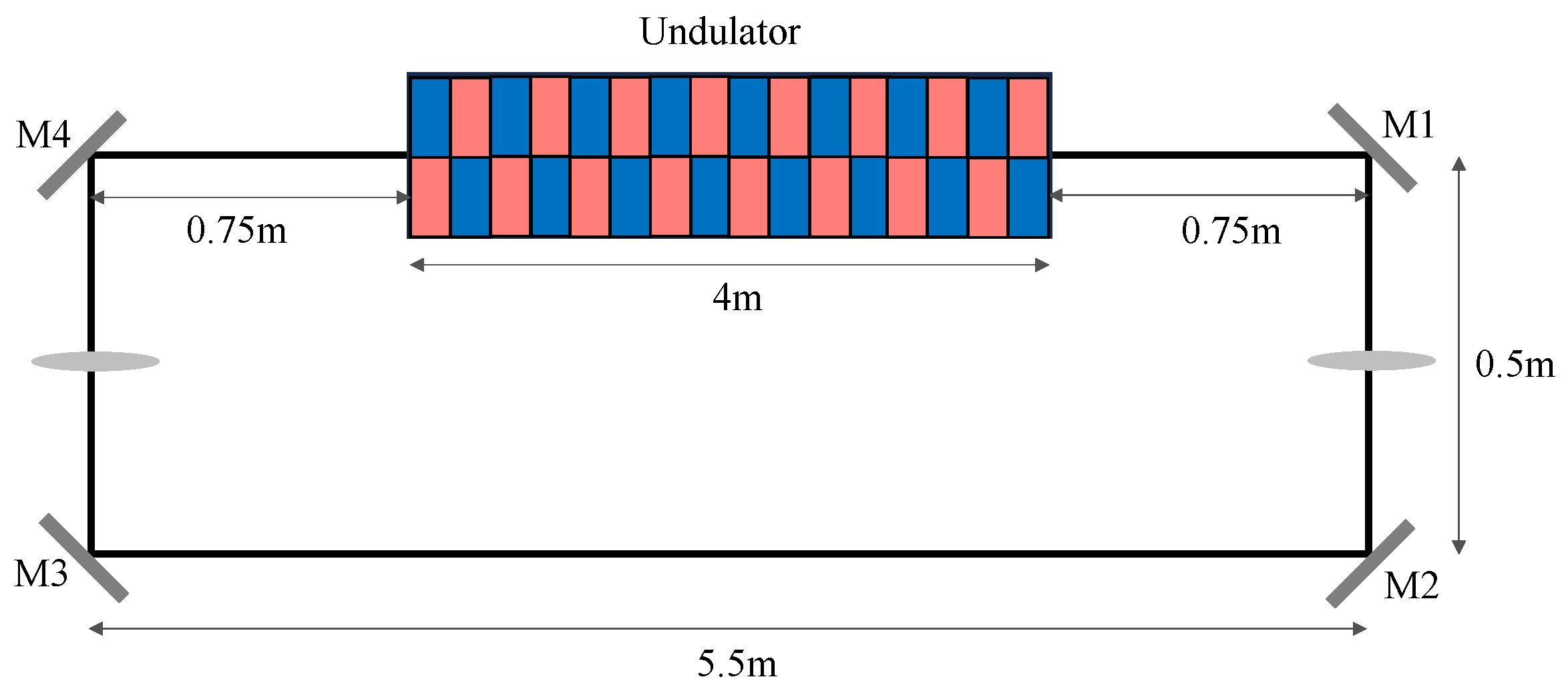
As a representative example, we consider a rectangular cavity composed of four diamond mirrors oriented at 45 degrees (see Figure 1), with Bragg resonance centered at 6.95 keV (Miller indices 220). The crystal thickness of the first mirror is 20 μm and results in a peak reflectivity of 98.9% and an FWHM reflective bandwidth of 150 meV. Mirrors 2-4 are 100 μm thick with a peak reflectivity of 99.6% and FWHM of 141 meV. The 4 m long undulator is centered between two mirrors, spaced 5.5 m apart in a rectangular X-ray cavity with roundtrip length m. Two compound refractive lenses (CRL) with m focal length are placed equidistant from each other to establish a stable transverse mode inside the cavity.
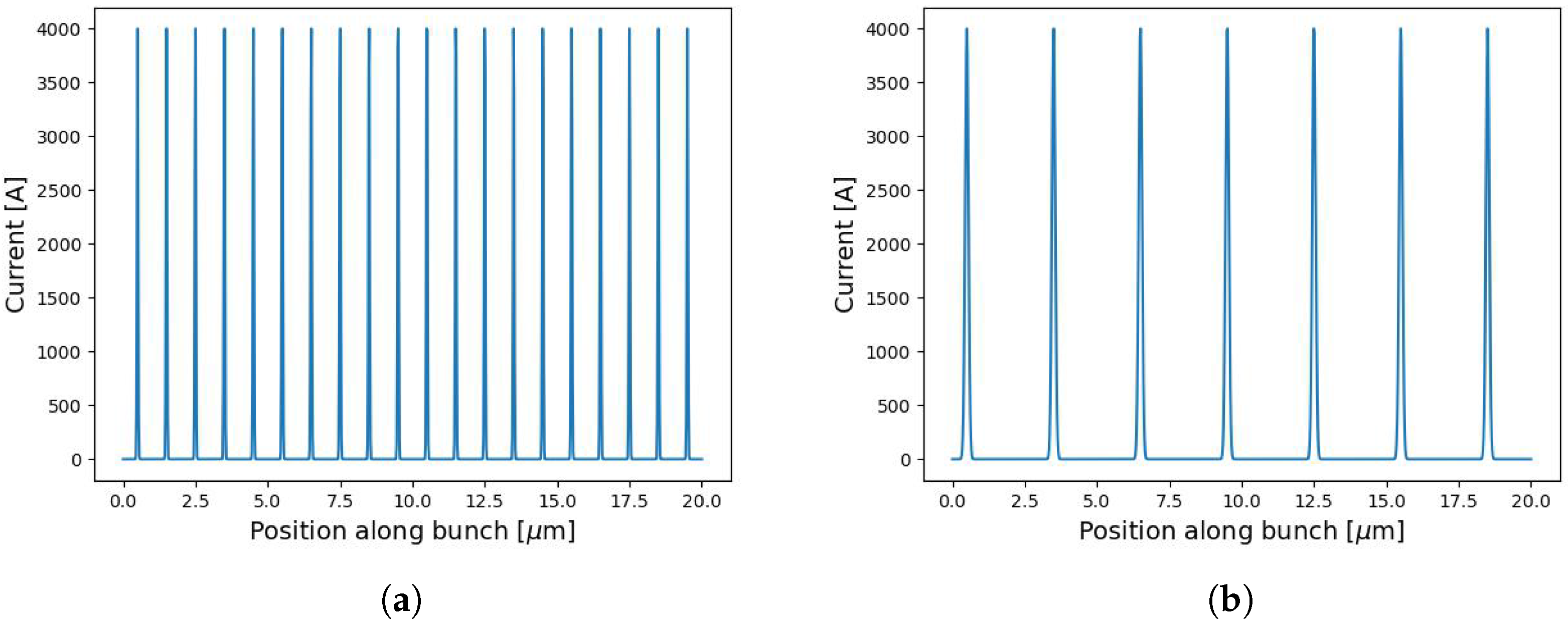
We base our study on the UC-XFEL design parameters [11]. The electron beam energy is 2.44 GeV. Six to eight electron pulses generated by the C-band linac, each separated by 40 nsec, are used to build up the intra-cavity power. The undulator period is mm, and the undulator strength is quadratically tapered to extract more FEL power. Given the design of UC-XFEL, a laser modulator is used to introduce periodical energy modulation to the electron beam. Through subsequent downstream acceleration and compression, the electron beam’s final longitudinal phase space takes the form of a bunch train [32]. The periodicity of the laser in the modulator determines the periodicity of the bunch train and the width of each individual bunch. In this report, we discuss two different cases: 1 μm and 3 μm laser modulation, with corresponding current profiles depicted in Figure 2. Additional beam parameters used in our simulation are listed in Table 1.
3. One-Dimension Study
We first demonstrate the feasibility of such a compact XRAFEL cavity using fast 1D simulations. The one-dimensional FEL simulation builds upon code developed by Z. Huang [33]. FEL radiation is produced according to the coupled longitudinal equations of motion for an electron given in [33,34,35,36] as:
where j indexes the individual electrons, is the electron phase, is the undulator wavenumber, is the normalized electron energy deviation from resonance, where is the Lorentz factor of the FEL resonant electron beam energy, K is the undulator strength parameter, and is the undulator Bessel function factor [33,34,35]. The field equation of a one-dimensional free-electron laser is given by:
where E is the electric field, is the electron density, and the angle brackets over denote an average taken over all electrons in the slice [33,34,35].
The cavity is approximated by a flattop filter in the frequency domain, with the center of the filter set to the resonant FEL frequency. Due to the short temporal duration of each bunch in the bunch train in Figure 2, the FEL output spectrum is much broader than the Bragg reflection window. Consequently, the spectral component falling within the Bragg reflection window is recirculated for repetitive interactions with the electron beams, while the portion of the spectrum lying outside the Bragg window is outcoupled.
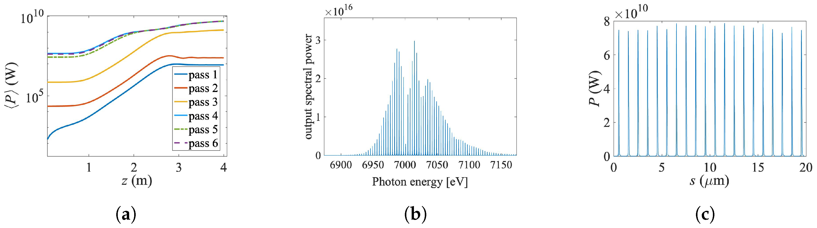
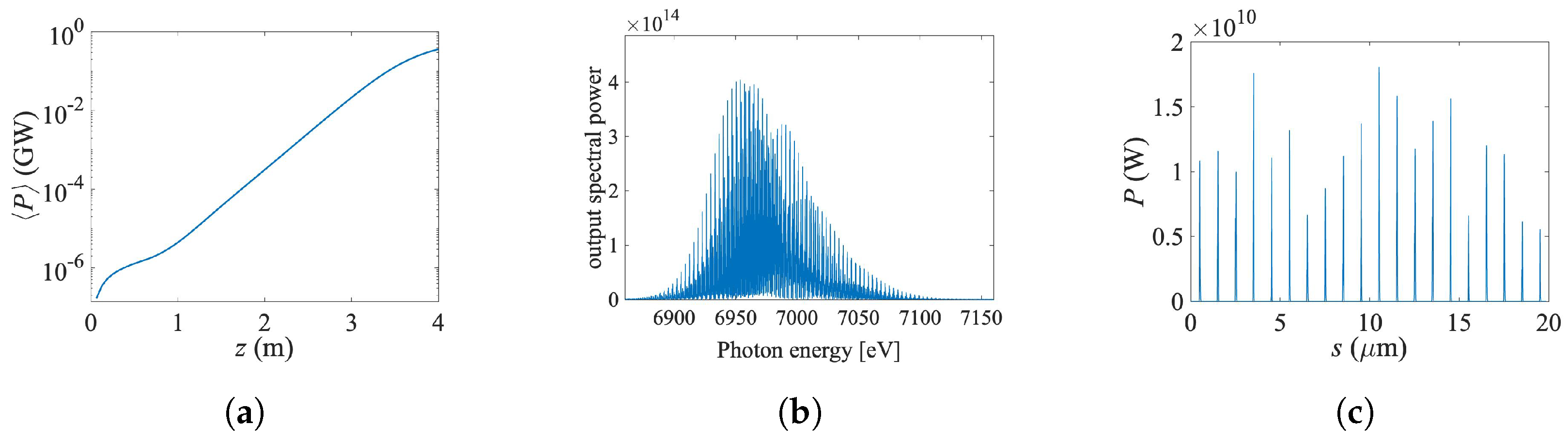
In the 1D simulations with the 1-μm case, the cavity reaches saturation within 6 e-beam pulses, as shown in Figure 3a. The resulting output spectrum exhibits a clean frequency-comb structure (Figure 3b). Further analysis on the stability and preservation of the comb structure is given in Appendix A. For comparison, we also present a single-pass SASE simulation in Figure 4. Notably, both the peak power and spectral brightness significantly exceed those of the SASE scenario.
3.1. Three-Dimension Study
Building upon the insights gained from our 1D simulations, we proceeded to perform 3D simulations for the compact XRAFEL scheme. The FEL process is modeled by the 3D FEL code GENESIS 1.3. In order to take advantage of the ultra-low emittance electron source from the UC-XFEL design, we insert a quadrupole FODO lattice superimposed to the undulator to focus the transverse size of the electron beams to about 1 μm. This likely necessitates use of permanent magnets placed inside the undulator gap. This design may be made more robust by using a new modified Panofsky quadrupole scheme [38].
A custom MPI-parallelized Python code takes the 3D complex field from GENESIS 1.3 and tracks it along the cavity. The field propagation in the drift spaces between the cavity optical components is modeled by the Fresnel equation. Each refractive lens is treated as a lossless parabolic phase mask in transverse space. The diamond mirrors are modeled using the dynamical theory of X-ray Bragg diffraction [39]. The recirculated radiation is dumped and used as the seed file for the next FEL interaction, and the field transmitted through the first Bragg mirror downstream of the undulator is recorded as the outcoupled radiation.
We consider two distinct beam profiles with 1 μm and 3 μm laser modulation, as depicted in Figure 2. For the 1 μm modulated e-beam, the current profile is made up of 20 Gaussian current spikes with a FWHM of 45 nm, each separated by 1 micron. The current profile for the 3 μm laser is 7 Gaussians with a FWHM of 135 nm and separated by 3 μm. The goal of the 3 μm study is to address slippage concerns. In our configuration, the slippage length is about 100 nm. The longer current spikes of the 3 μm current modulation is notably longer than the slippage length, resulting in enhanced FEL performance in terms of both power output and spectral width.
3.1.1. 1 μm Current
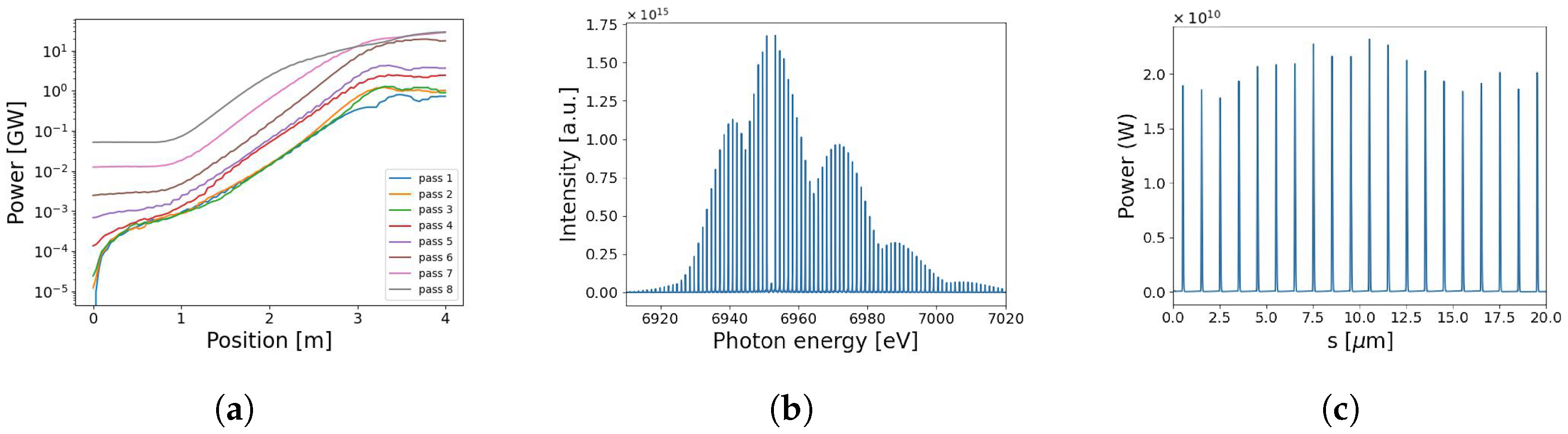
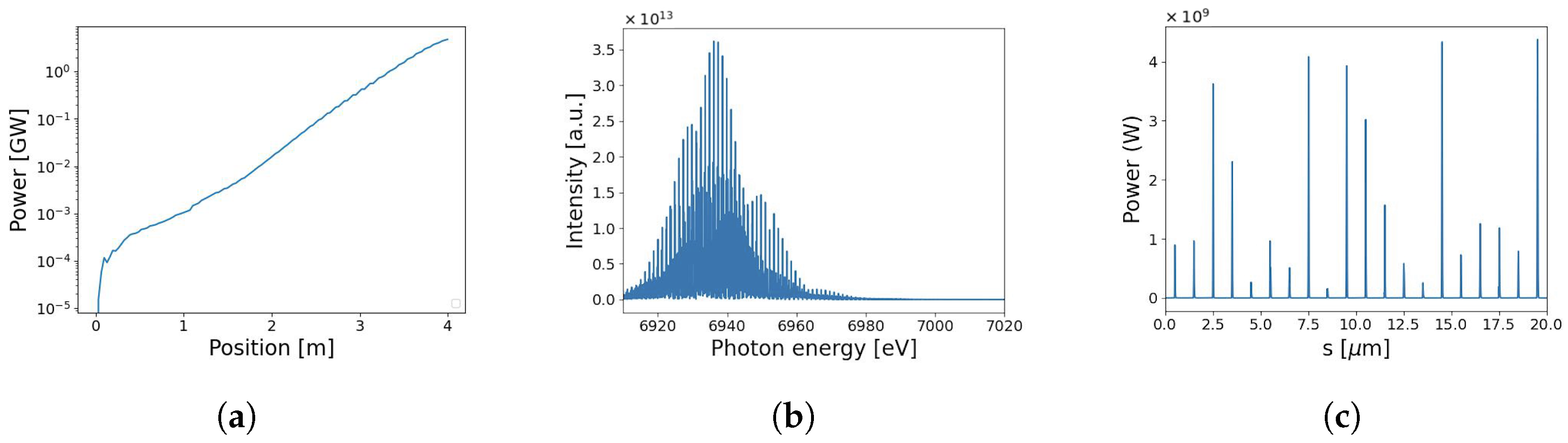
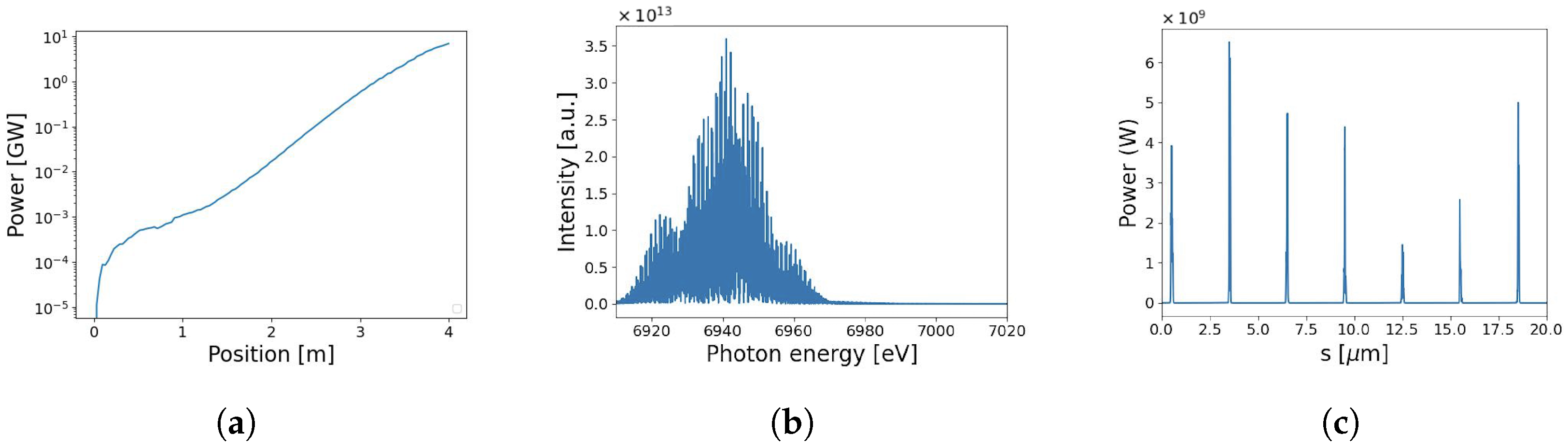
In Figure 5a we show the 3D simulation result of the pass-to-pass power build-up process of the UC-XRAFEL using electron beams with 1 μm laser modulation. The FEL peak power reaches 20 GW within 7 electron shots, a result that aligns with our 1D findings. The intra-cavity seed power reaches 52 MW, and the undulator taper is optimized given the strong seed. Figure 5b,c are the spectrum and power profile of the outcoupled radiation after 7 electron shots. The single-pass SASE simulation with no tapering and the same electron beam parameters is included in Figure 6 as a comparison. As observed in both 1D and 3D results, the XRAFEL outputs exhibit significantly cleaner and more uniform temporal and spectral characteristics, due to the strong intra-cavity seed.
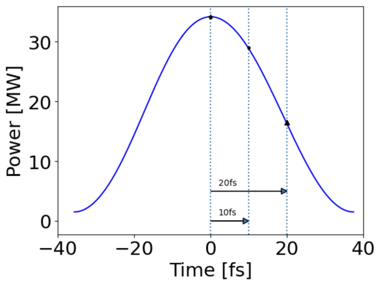
The precise synchronization of the electron bunch spacing and the radiation arrival time is investigated and depicted in Figure 7. The input seed is shorter (∼40 fs, FWHM) than the electron bunch length (67 fs). The cavity length (12 m) is matched with the roundtrip frequency of the electron beam: m.
A shift of 10 fs of the seed radiation with respect to the electron bunch results in approximately 85% of the seed power used for FEL interaction and amplification. A more dramatic offset between the electron bunch length and the round trip cavity length of 20 fs results in only 48% of the input seed feeding the FEL interaction. The tolerance on the cavity length is set by this synchronization condition, which corresponds to approximately 3–6 μm. However, since the FEL is in the post-saturation regime, a conservative offset will not likely introduce a significant energy jitter.
3.1.2. 3 μm Current
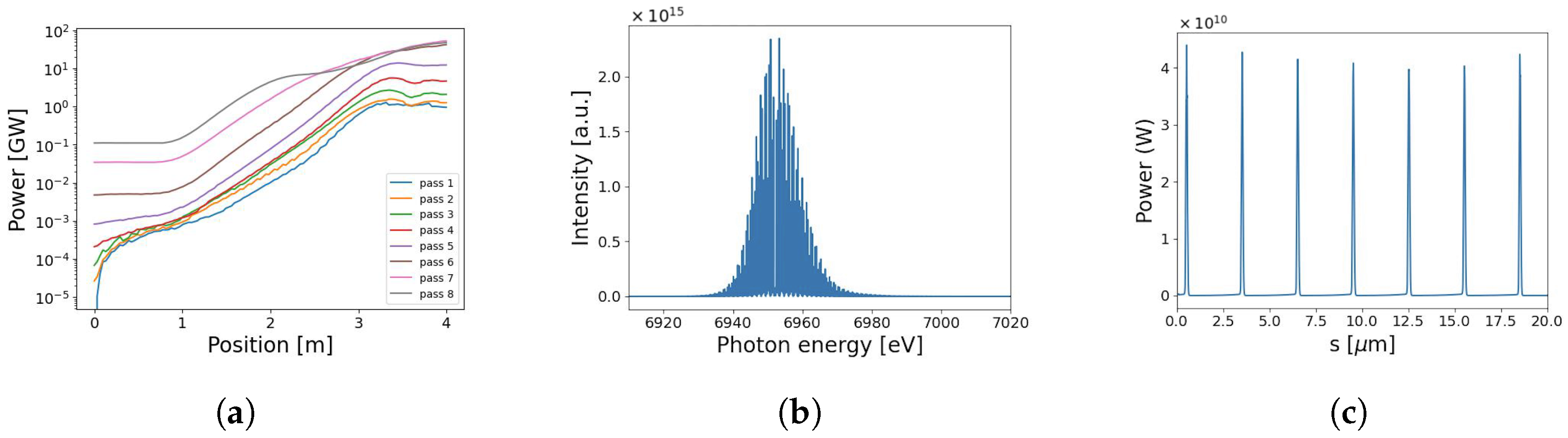
Due to the relatively short duration of the electron beam current spikes in the 1 μm scenario, the power gain is constrained by slippage effects. Increasing the time duration of the e-beam current spikes can enhance FEL gain. In Figure 8 and Figure 9, we present the outcomes of our 3D simulations on the 3 μm modulated electron beam, the current profile of which is depicted in Figure 2b. After six passes, the output peak saturation power reaches 44 GW after transmitting the first mirror. This represents a significant two-fold increase in power compared to the 1 μm case. The FEL bandwidth is also narrower by more than a factor of 2 compared to the 1 μm case. In the case of a single-pass SASE simulation for a 3 μm modulated beam, a peak power output of up to 6.5 GW is attained, indicating a similar level of improvement compared to the 1 μm case. The SASE simulation uses an undulator with no tapering. Notably, the spectral brightness of XRAFEL exhibits a substantial improvement, surpassing that of SASE by almost two orders of magnitude.
4. Discussion and Conclusions
In this report, we demonstrate the successful amplification of initial SASE radiation at 6.95 keV to powers up to the tens of GW level within a few passes in a 12 m round-trip cavity. Our investigation involved two distinct electron beam current profiles employed in the UC-XRAFEL cavity design, showcasing a substantial enhancement in peak power compared to SASE. For the 1 μm current profile, we achieved a 25 GW peak power output compared to 4.5 GW achieved with SASE. Similarly, the 3 μm current profile yielded a 44 GW peak power output compared to the 6.5 GW observed with SASE. While the FEL does not reach a perfect steady state, we are limited by the number of electron bunches in play: the 12-m cavity and the electron bunch repetition rate accommodates eight passes, in which the peak saturation power for both 1 μm and 3 μm is reached by pass seven. By employing a 3 μm modulated electron beam instead of a 1 μm one, we observe a notable increase in the maximum power output and a narrower spectrum.
The distinctions between the SASE and XRAFEL outputs are readily apparent. The SASE spectrum exhibits a broadband nature and maintains its characteristic spikes attributed to self-amplified shot noise. In contrast, the seeded spectrum within the XRAFEL output possesses a smoother and more stable shape. This cleaner spectral profile of the XRAFEL output results from the dominance of a robust intra-cavity seed power over the shot noise inherent in SASE. Furthermore, due to the increased power and the cleaner spectral structure, the spectral brightness of XRAFEL is enhanced by almost two orders of magnitude compared to SASE.
We note in passing that the XRAFEL from a current modulated beam generates a train of phase-locked X-ray intensity profile and the corresponding spectral spikes, which can be further explored for various applications. For applications needing the highest spectral brightness, a more uniform electron bunch profile will generate a more uniform X-ray temporal profile, and hence, the spectral brightness will be more concentrated in a single spike with the maximum brightness. In the near future, we plan to explore different bunch compression schemes to generate a compact single-pulse current distribution, while mitigating deleterious collective effects. This will serve to further optimize the spectral brightness.
To summarize, we report an XRAFEL design based on the current UC-XFEL configuration and present first simulation studies to obtain an estimate of the performance of the scheme. Our results show that an XRAFEL can dramatically enhance the temporal coherence and increase the spectral brightness of the radiation in the hard X-ray regime (6.95 keV) without increasing the footprint of the FEL configuration. The proposed compact, fully coherent, and high-flux hard X-ray source holds promise as a valuable candidate for a wide range of high-impact applications in both academia and industry.
Author Contributions
Conceptualization, J.R.; methodology, J.T.; software, Z.H.; validation, J.T. and Z.H.; formal analysis, M.S., J.T. and Z.H.; investigation, Z.H.; resources, Z.H.; data curation, M.S. and J.T.; writing—original draft preparation, M.S.; writing—review and editing, J.R., J.T. and Z.H.; visualization, J.T.; supervision, J.T. and Z.H.; funding acquisition, Z.H. All authors have read and agreed to the published version of the manuscript.
Funding
This work was supported by the U.S. Department of Energy, Office of Science, Office of Basic Energy Sciences under Contract No. DE-AC02-76SF00515.
Data Availability Statement
The data presented in this study are available on request from the corresponding author.
Acknowledgments
The authors would like to thank River Robles for helpful discussions of and work pertaining to the generation of the electron bunch current profile, as well as constructive feedback on the work presented here.
Conflicts of Interest
The authors declare no conflicts of interest. The funders had no role in the design of the study; in the collection, analyses, or interpretation of data; in the writing of the manuscript; or in the decision to publish the results.
Abbreviations
The following abbreviations are used in this manuscript:
| FEL | Free-electron laser |
| XFEL | X-ray free-electron laser |
| XRAFEL | X-ray regenerative amplifier free-electron laser |
| UC-XFEL | Ultra-compact X-ray free-electron laser |
| UC-XRAFEL | Ultra-Compact X-ray regenerative amplifier free-electron laser |
| SASE | Self-amplified spontaneous emission |
| SLAC | Stanford Linear Accelerator Center |
Appendix A. Stability of the Input SASE Seed on the Spectra
An additional study is conducted to determine the effect of the input SASE seed, which is generated by a random number in GENESIS 1.3.
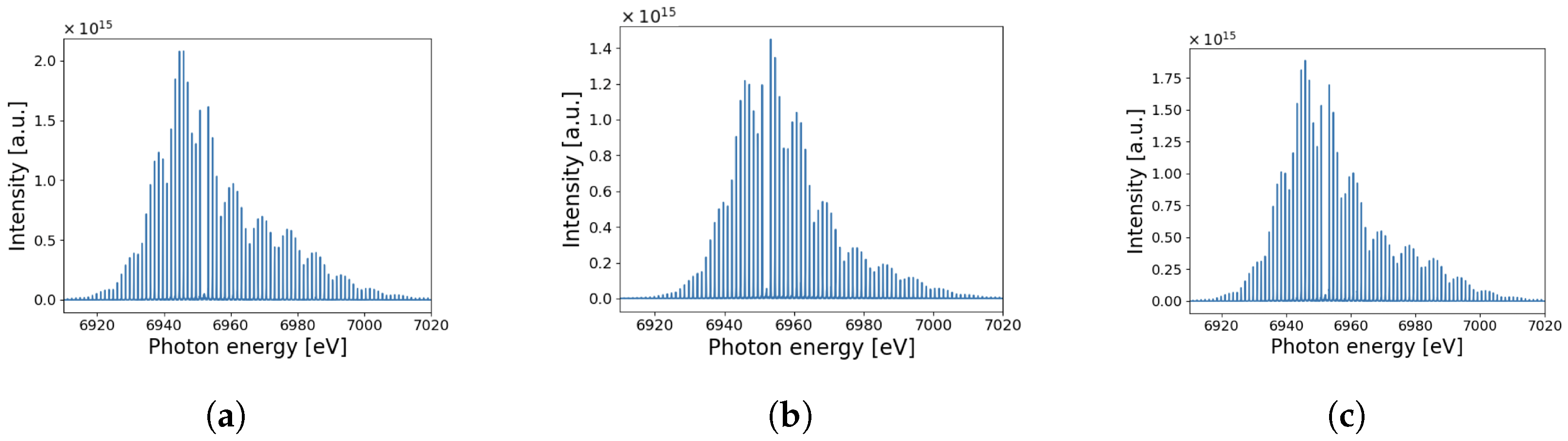
In particular, we focus on how the spectral brightness and shape evolves with three different initial SASE seeds, for the 1 um current profile. The three spectra shown in Figure A1 are for the seventh pass through the cavity. There are slight fluctuations in the spectral brightness between the three runs due to the changing random numbers generating the initial SASE profile, but the shape and comb-like features of the spectral profiles are preserved.
Figure A1.
Spectra after the seventh round trip of three different UC-XRAFEL runs (a–c) using different random SASE seeds for 1 μm modulated electron beams in order to determine the stability of the UC-XRAFEL seventh pass results using GENESIS 1.3. The spectra are recorded after transmitting through mirror 1.

References
- Cornacchia, M. Linac Coherent Light Source (LCLS) Design Study Report; Technical Report No. SLAC-R-521; SLAC National Accelerator Lab.: Menlo Park, CA, USA, 1998. [Google Scholar] [CrossRef]
- Eom, I.; Chun, S.H.; Lee, J.H.; Nam, D.; Ma, R.; Park, J.; Park, S.; Park, S.H.; Yang, H.; Nam, I.; et al. Recent Progress of the PAL-XFEL. Appl. Sci. 2022, 12, 1010. [Google Scholar] [CrossRef]
- Abela, R.; Aghababyan, A.; Altarelli, M.; Altucci, C.; Amatuni, G.; Anfinrud, P.; Audebert, P.; Ayvazyan, V.; Baboi, N.; Baehr, J.; et al. XFEL: The European X-ray Free-Electron Laser-Technical Design Report; DESY: Hamburg, Germany, 2006. [Google Scholar] [CrossRef]
- Pandey, S.; Bean, R.; Sato, T.; Poudyal, I.; Bielecki, J.; Cruz Villarreal, J.; Yefanov, O.; Mariani, V.; White, T.A.; Kupitz, C.; et al. Time-resolved serial femtosecond crystallography at the European XFEL. Nat. Methods 2020, 17, 73–78. [Google Scholar] [CrossRef] [PubMed]
- Sobolev, E.; Zolotarev, S.; Giewekemeyer, K.; Bielecki, J.; Okamoto, K.; Reddy, H.K.N.; Andreasson, J.; Ayyer, K.; Barak, I.; Bari, S.; et al. Megahertz single-particle imaging at the European XFEL. Commun. Phys. 2020, 3, 97. [Google Scholar] [CrossRef]
- Berrah, N.; Fang, L.; Murphy, B.; Osipov, T.; Ueda, K.; Kukk, E.; Feifel, R.; van der Meulen, P.; Salen, P.; Schmidt, H.T.; et al. Double-core-hole spectroscopy for chemical analysis with an intense X-ray femtosecond laser. Proc. Natl. Acad. Sci. USA 2011, 108, 16912–16915. [Google Scholar] [CrossRef] [PubMed]
- Suga, M.; Akita, F.; Sugahara, M.; Kubo, M.; Nakajima, Y.; Nakane, T.; Yamashita, K.; Umena, Y.; Nakabayashi, M.; Yamane, T.; et al. Light-induced structural changes and the site of O=O bond formation in PSII caught by XFEL. Nature 2017, 543, 131–135. [Google Scholar] [CrossRef] [PubMed]
- Lehmkühler, F.; Dallari, F.; Jain, A.; Sikorski, M.; Möller, J.; Frenzel, L.; Lokteva, I.; Mills, G.; Walther, M.; Sinn, H.; et al. Emergence of anomalous dynamics in soft matter probed at the European XFEL. Proc. Natl. Acad. Sci. USA 2020, 117, 24110–24116. [Google Scholar] [CrossRef] [PubMed]
- Kao, C.C. Challenges and opportunities for the next decade of XFELs. Nat. Rev. Phys. 2020, 2, 340–341. [Google Scholar] [CrossRef]
- Nanni, E.; Graves, W.; Moncton, D. Nanomodulated electron beams via electron diffraction and emittance exchange for coherent x-ray generation. Phys. Rev. Accel. Beams 2018, 21, 014401. [Google Scholar] [CrossRef]
- Rosenzweig, J.B.; Majernik, N.; Robles, R.R.; Andonian, G.; Camacho, O.; Fukasawa, A.; Kogar, A.; Lawler, G.; Miao, J.; Musumeci, P.; et al. An ultra-compact X-ray free-electron laser. New J. Phys. 2020, 22, 093067. [Google Scholar] [CrossRef]
- Wang, W.; Feng, K.; Ke, L.; Yu, C.; Xu, Y.; Qi, R.; Chen, Y.; Qin, Z.; Zhang, Z.; Fang, M.; et al. Free-electron lasing at 27 nanometres based on a laser wakefield accelerator. Nature 2021, 595, 516–520. [Google Scholar] [CrossRef]
- Rosenzweig, J.B.; Andonian, G.; Agustsson, R.; Anisimov, P.M.; Araujo, A.; Bosco, F.; Carillo, M.; Chiadroni, E.; Giannessi, L.; Huang, Z.; et al. A high-flux compact X-ray free-electron laser for next generation chip metrology needs. Preprints 2023, 2023111639. [Google Scholar] [CrossRef]
- Huang, Z.; Ruth, R.D. Fully Coherent X-ray Pulses from a Regenerative-Amplifier Free-Electron Laser. Phys. Rev. Lett. 2006, 96, 144801. [Google Scholar] [CrossRef]
- Marcus, G.; Halavanau, A.; Huang, Z.; Krzywinski, J.; MacArthur, J.; Margraf, R.; Raubenheimer, T.; Zhu, D. Refractive Guide Switching a Regenerative Amplifier Free-Electron Laser for High Peak and Average Power Hard X rays. Phys. Rev. Lett. 2020, 125, 254801. [Google Scholar] [CrossRef]
- Rauer, P.; Decking, W.; Lipka, D.; Thoden, D.; Wohlenberg, T.; Bahns, I.; Brueggmann, U.; Casalbuoni, S.; Di Felice, M.; Dommach, M.; et al. Cavity based X-ray free electron laser demonstrator at the European X-ray Free Electron Laser facility. Phys. Rev. Accel. Beams 2023, 26, 020701. [Google Scholar] [CrossRef]
- Tang, J.; Zhang, Z.; Morgan, J.; Hemsing, E.; Huang, Z. Active Q-Switched X-ray Regenerative Amplifier Free-Electron Laser. Phys. Rev. Lett. 2023, 131, 055001. [Google Scholar] [CrossRef] [PubMed]
- Shvyd’ko, Y.V.; Stoupin, S.; Cunsolo, A.; Said, A.H.; Huang, X. High-reflectivity high-resolution X-ray crystal optics with diamonds. Nat. Phys. 2010, 6, 196–199. [Google Scholar] [CrossRef]
- Shvyd’Ko, Y.; Stoupin, S.; Blank, V.; Terentyev, S. Near-100% Bragg reflectivity of X-rays. Nat. Photonics 2011, 5, 539–542. [Google Scholar] [CrossRef]
- Kim, K.J.; Shvyd’ko, Y.; Reiche, S. A Proposal for an X-ray Free-Electron Laser Oscillator with an Energy-Recovery Linac. Phys. Rev. Lett. 2008, 100, 244802. [Google Scholar] [CrossRef] [PubMed]
- Qin, W.; Huang, S.; Liu, K.X.; Kim, K.J.; Lindberg, R.R.; Bane, K.L.F.; Ding, Y.; Huang, Z.; Marcus, G.; Maxwell, T.J. Start-to-End Simulations for an X-ray FEL Oscillator at the LCLS-II and LCLS-II-HE. In Proceedings of the 38th International Free Electron Laser Conference (FEL'17), Santa Fe, NM, USA, 20–25 August 2017; JACoW: Geneva, Switzerland, 2018; pp. 247–250. [Google Scholar] [CrossRef]
- Huang, N.S.; Liu, Z.P.; Deng, B.J.; Zhu, Z.H.; Li, S.H.; Liu, T.; Qi, Z.; Yan, J.W.; Zhang, W.; Xiang, S.W.; et al. The MING proposal at SHINE: Megahertz cavity enhanced X-ray generation. Nucl. Sci. Tech. 2023, 34, 6. [Google Scholar] [CrossRef]
- Margraf, R.; Robles, R.; Halavanau, A.; Kryzywinski, J.; Li, K.; MacArthur, J.; Osaka, T.; Sakdinawat, A.; Sato, T.; Sun, Y.; et al. Low-loss stable storage of 1.2 Å X-ray pulses in a 14 m Bragg cavity. Nat. Photonics 2023, 17, 878–882. [Google Scholar] [CrossRef]
- Wollenweber, L.; Preston, T.R.; Descamps, A.; Cerantola, V.; Comley, A.; Eggert, J.H.; Fletcher, L.B.; Geloni, G.; Gericke, D.O.; Glenzer, S.H.; et al. High-resolution inelastic X-ray scattering at the high energy density scientific instrument at the European X-ray Free-Electron Laser. Rev. Sci. Instruments 2021, 92, 013101. [Google Scholar] [CrossRef]
- Kowalewski, M.; Fingerhut, B.P.; Dorfman, K.E.; Bennett, K.; Mukamel, S. Simulating Coherent Multidimensional Spectroscopy of Nonadiabatic Molecular Processes: From the Infrared to the X-ray Regime. Chem. Rev. 2017, 117, 12165–12226. [Google Scholar] [CrossRef] [PubMed]
- Bergmann, U.; Kern, J.; Schoenlein, R.W.; Wernet, P.; Yachandra, V.K.; Yano, J. Using X-ray free-electron lasers for spectroscopy of molecular catalysts and metalloenzymes. Nat. Rev. Phys. 2021, 3, 264–282. [Google Scholar] [CrossRef]
- Aquila, A.; Barty, A.; Bostedt, C.; Boutet, S.; Carini, G.; dePonte, D.; Drell, P.; Doniach, S.; Downing, K.H.; Earnest, T.; et al. The linac coherent light source single particle imaging road map. Struct. Dyn. 2015, 2, 041701. [Google Scholar] [CrossRef] [PubMed]
- Glover, T.E.; Fritz, D.M.; Cammarata, M.; Allison, T.K.; Coh, S.; Feldkamp, J.M.; Lemke, H.; Zhu, D.; Feng, Y.; Coffee, R.N.; et al. X-ray and optical wave mixing. Nature 2012, 488, 603–608. [Google Scholar] [CrossRef] [PubMed]
- Adams, B.W.; Buth, C.; Cavaletto, S.M.; Evers, J.; Harman, Z.; Keitel, C.H.; Pálffy, A.; Picón, A.; Röhlsberger, R.; Rostovtsev, Y.; et al. X-ray quantum optics. J. Mod. Opt. 2013, 60, 2–21. [Google Scholar] [CrossRef]
- Reiche, S. Numerical Studies for a Single Pass High Gain Free Electron Laser. Ph.D. Thesis, Hamburg University, Hamburg, Germany, 2000. [Google Scholar]
- Reiche, S. GENESIS 1.3: A fully 3D time-dependent FEL simulation code. Nucl. Instrum. Methods Phys. Res. Sect. A: Accel. Spectrometers Detect. Assoc. Equip. 1999, 429, 243–248. [Google Scholar] [CrossRef]
- Schreiber, S.; Faatz, B.; Feldhaus, J.; Honkavaara, K.; Treusch, R. FEL User Facility FLASH. Proc. IPAC 2010, 10, 2149–2151. [Google Scholar]
- Kim, K.J.; Huang, Z.; Lindberg, R. Synchrotron Radiation and Free-Electron Lasers: Principles of Coherent X-ray Generation; Cambridge University Press: Cambridge, UK, 2017. [Google Scholar] [CrossRef]
- Piovella, N.; Volpe, L. A Review of High-Gain Free-Electron Laser Theory. Atoms 2021, 9, 28. [Google Scholar] [CrossRef]
- Schmüser, P.; Dohlus, M.; Dohlus, J. Refinements of the One-Dimensional FEL Theory. In Ultraviolet and Soft X-ray Free-Electron Lasers: Introduction to Physical Principles, Experimental Results, Technological Challenges; Schmüser, P., Dohlus, M., Rossbach, J., Eds.; Springer Tracts in Modern Physics; Springer: Berlin/Heidelberg, Germany, 2009; pp. 83–101. [Google Scholar] [CrossRef]
- Anisimov, P. Canonical Formulation of 1D FEL Theory Revisited, Quantized and Applied to Electron Evolution. In Proceedings of the 38th International Free Electron Laser Conference, FEL2017, Santa Fe, NM, USA, 20–25 August 2017. [Google Scholar] [CrossRef]
- Kroll, N.; Morton, P.; Rosenbluth, M. Free-electron lasers with variable parameter wigglers. IEEE J. Quantum Electron. 1981, 17, 1436–1468. [Google Scholar] [CrossRef]
- Pound, B.A.; Candler, R.; Crisp, S.; Ody, A.; Musumeci, P.; Rosenzweig, J. Focusing of a relativistic electron beam with a microfabricated quadrupole magnet. Phys. Rev. Accel. Beams 2023, 26, 042401. [Google Scholar] [CrossRef]
- Lindberg, R.R.; Shvyd’ko, Y.V. Time dependence of Bragg forward scattering and self-seeding of hard x-ray free-electron lasers. Phys. Rev. Spec. Top. Accel. Beams 2012, 15, 050706. [Google Scholar] [CrossRef]
Figure 1.
The setup of the 12 m round-trip cavity designed for possible use in the UC-XFEL facility.
Figure 1.
The setup of the 12 m round-trip cavity designed for possible use in the UC-XFEL facility.

Figure 2.
(a) 1 μm current profile along the bunch length. The beam is composed of 20 Gaussian functions, each separated by 1 μm. (b) 3 μm current profile along the bunch length, with separation 3 μm.
Figure 2.
(a) 1 μm current profile along the bunch length. The beam is composed of 20 Gaussian functions, each separated by 1 μm. (b) 3 μm current profile along the bunch length, with separation 3 μm.

Figure 3.
1D UC-XRAFEL simulation results for the 1-μm current modulation. (a) The gain curves after each recirculation pass for optimal tapering [37]. (b) The output spectrum after the 5th pass. (c) The power profile of the out-coupled radiation for the 5th pass, with a maximum power along the bunch peaking at 80 GW.

Figure 4.
1D SASE simulation results for the 1-μm current modulation. (a) Gain curve, (b) output spectrum, and (c) power profile for single-pass SASE with no tapering. The maximum power peaks at 20 GW.
Figure 4.
1D SASE simulation results for the 1-μm current modulation. (a) Gain curve, (b) output spectrum, and (c) power profile for single-pass SASE with no tapering. The maximum power peaks at 20 GW.

Figure 5.
Three-dimensional simulation results of UC-XRAFEL with 1 μm modulated electron beams. Each plot describes (a) the gain curves after each pass through the cavity, (b) the output spectrum after the 7th pass, and (c) the power profile of the out-coupled radiation for the 7th pass. The maximum output power along the bunch peaks at 25 GW.

Figure 6.
Three-dimensional simulation results of a single-pass, non-tapered SASE with 1 μm modulated electron beams. Each plot describes (a) the gain curve, (b) the output spectrum, and (c) the power profile. The maximum output power attainable by single-pass SASE for a 1 μm current profile is 4.5 GW.

Figure 7.
Seed profile for the 7th pass of the 1 μm current profile. A 10–20 fs offset of the seed input from the electron bunch length results in a partial decrease of the input seed power.
Figure 7.
Seed profile for the 7th pass of the 1 μm current profile. A 10–20 fs offset of the seed input from the electron bunch length results in a partial decrease of the input seed power.

Figure 8.
Three-dimensional simulation results of UC-XRAFEL with 3 μm modulated electron beams. Each plot shows (a) the gain curve (b) the output spectrum, and (c) the power profile. A maximum power of 44 GW is reached after the sixth pass.
Figure 8.
Three-dimensional simulation results of UC-XRAFEL with 3 μm modulated electron beams. Each plot shows (a) the gain curve (b) the output spectrum, and (c) the power profile. A maximum power of 44 GW is reached after the sixth pass.

Figure 9.
Three-dimensional simulation results of a single-pass SASE with 3 μm modulated electron beams. (a) Gain curve, (b) output spectrum, and (c) power profile for SASE with no tapering. The maximum power along the bunch peaks at 6.5 GW.
Figure 9.
Three-dimensional simulation results of a single-pass SASE with 3 μm modulated electron beams. (a) Gain curve, (b) output spectrum, and (c) power profile for SASE with no tapering. The maximum power along the bunch peaks at 6.5 GW.


Table 1.
Summary of parameters for the ultra-compact X-ray regenerative amplifier free-electron laser (UC-XRAFEL).
Table 1.
Summary of parameters for the ultra-compact X-ray regenerative amplifier free-electron laser (UC-XRAFEL).
| Parameter | Units | Value |
|---|---|---|
| Energy | GeV | 2.44 |
| Energy spread | % | 0.03 |
| Normalized transverse emittance | nm-rad | 75 |
| Peak current | kA | 4.0 |
| Undulator parameter, K | 0.50 | |
| Undulator period | mm | 6.5 |
| Undulator length | m | 4.0 |
| Radiation wavelength | Å | 1.783 |
| Photon energy | keV | 6.95 |
| Cavity roundtrip length, | m | 12 |
| CRL focal length, f | m | 3 |
Disclaimer/Publisher’s Note: The statements, opinions and data contained in all publications are solely those of the individual author(s) and contributor(s) and not of MDPI and/or the editor(s). MDPI and/or the editor(s) disclaim responsibility for any injury to people or property resulting from any ideas, methods, instructions or products referred to in the content. |
© 2024 by the authors. Licensee MDPI, Basel, Switzerland. This article is an open access article distributed under the terms and conditions of the Creative Commons Attribution (CC BY) license (https://creativecommons.org/licenses/by/4.0/).
Share and Cite
MDPI and ACS Style
Singleton, M.; Rosenzweig, J.; Tang, J.; Huang, Z. An Ultra-Compact X-ray Regenerative Amplifier Free-Electron Laser. Instruments 2024, 8, 2. https://doi.org/10.3390/instruments8010002
AMA Style
Singleton M, Rosenzweig J, Tang J, Huang Z. An Ultra-Compact X-ray Regenerative Amplifier Free-Electron Laser. Instruments. 2024; 8(1):2. https://doi.org/10.3390/instruments8010002
Chicago/Turabian StyleSingleton, Madison, James Rosenzweig, Jingyi Tang, and Zhirong Huang. 2024. "An Ultra-Compact X-ray Regenerative Amplifier Free-Electron Laser" Instruments 8, no. 1: 2. https://doi.org/10.3390/instruments8010002