Article

A Concept for a Multipurpose Time-of-Flight Neutron Reflectometer at Compact Neutron Sources

by
Raul-Victor Erhan
1,2,*,
Victor-Otto de Haan
3,
Christoph Frommen
1,
Kenneth Dahl Knudsen
1,
Isabel Llamas-Jansa
1 and
Bjørn Christian Hauback
1
1
Department for Hydrogen Technology, Institute for Energy Technology, Instituttveien 18, 2007 Kjeller, Norway
2
Department of Nuclear Physics, Horia Hulubei National Institute for Research and Development in Physics and Nuclear Engineering, Reactorului 30, 077125 Măgurele, Romania
3
BonPhysics B.V., Laan van Heemstede 38, 3297 AJ Puttershoek, The Netherlands
*
Author to whom correspondence should be addressed.
Instruments 2024, 8(2), 30; https://doi.org/10.3390/instruments8020030
Submission received: 28 December 2023 / Revised: 14 April 2024 / Accepted: 16 April 2024 / Published: 24 April 2024

Abstract

:
The design of a time-of-flight neutron reflectometer proposed for the new generation of compact neutron sources is presented. The reflectometer offers the possibility to use spin-polarized neutrons. The reflectometer design presented here takes advantage of a cold neutron source and uses neutrons with wavelengths in the range of 2–15 Å for the unpolarized mode. In general, due to tight spatial restrictions and the need to avoid moving parts inside the beam channel, a multi-channel collimator guide and reflective neutron guide are used for the first section of the instrument. This enables definition of the desired wavelength band and easy selection of one out of three different Q-resolutions. A low background for the collimator system and the reflectometer is ensured by employing a tangential beam channel and an in-channel sapphire filter. The second section is the time-of-flight (TOF) system, which uses a double-disk neutron chopper followed by polarization elements, the sample environment and the neutron detector system. Monte Carlo simulations and neutron beamline intensity measurements are presented. The design considerations are adoptable for neutron sources where space is limited and sections of the instrument are in a high-radiation environment.

1. Introduction

To address the growing need for material research with neutrons and to compensate for the closure of existing facilities due to aging, new compact neutron sources are being designed and constructed [1]. Most of these designs are based on pulsed proton beams hitting a target. When these pulses are short enough, they can be used as the starting pulse of a time-of-flight system enabling the determination of the neutron wavelength. As these sources need to be compact, one can assume that in many cases the instruments at these sources should also be compact. Further, the compactness of the instrument is a step towards increasing the intensity. One can imagine that in the future, other sources will be developed that are based on a more continuous production of neutrons [2], and in such cases, one will need an optimal way to measure the neutron wavelength. A time-of-flight system based on a Van Well chopper can be an appropriate choice is such cases.
Neutron reflectometry (NR) is a versatile technique for characterization of surfaces and interfaces in energy materials (for hydrogen storage, battery applications and solar cell components), for nanomagnetism (magnetic thin films and multilayers) and biological membranes (interaction of natural and artificial membranes with surrounding media), as well as for materials adsorbed at the solid–liquid interface.
The principle is that a defined neutron beam hits the surface under investigation at a grazing angle and is partly transmitted and partly reflected there. The measured quantity is the intensity of the reflected beam, to which the reflectance of the surface and of all the parallel interfaces underneath contribute. In a simplified picture, the contrast between the layers defines the amplitude, and the thicknesses of the films defines the phase of the reflected neutron. The measured signal is the result of the interference of all reflected waves [3]. The corresponding scattered waves interfere constructively or destructively, resulting in oscillations that can be observed as reflectivity curves [4]. Reflectivity curves can be calculated by tracing the neutron wave function through the depth profile of the system [5]. The distance between the peaks or valleys of these oscillations gives information about the thickness of the layers in the sample [6] and the variations in scattering length density within the sample layers [7]. To interpret the experimental results, a chi-square probability distribution is used to fit the observed data, leading to information about the layer thickness [8]. Furthermore, polarized neutron reflectometry (PNR) enables the detailed investigation of depth-resolved magnetic structures in thin films and multilayer magnetic systems [9,10].
The presented neutron reflectometer (named FREYJA) was initially designed as a part the Norwegian Center for Neutron Research—NcNeutron [11]—and can be used as a model for other neutron instruments to be implemented at neutron sources. NcNeutron plays an important role keeping the scientific interest of the user community towards the use of neutron facilities, particularly the upcoming European Spallation Source (ESS) in Lund, Sweden and other planned setups at compact neutron sources (CNSs), cyclotron or even at the new laser-driven neutron sources [1]. For this purpose, a prototype setup was designed and partially tested at the Institute for Energy Technology (IFE), Norway.
The FREYJA instrument is designed as a time-of-flight (TOF) neutron reflectometer. The general advantage of the TOF mode of operation over monochromatic instruments is that a wide Q-range can be investigated using a single angle of incidence, with resolution and flux well-adjusted to the experimental requirements [12]. FREYJA employs a horizontal scattering geometry (sample surface vertical), encouraging the study of solid/solid, solid/air and solid/liquid interfaces. The instrument was planned to include the capacity to study magnetic samples using spin-polarized neutrons.
As the neutron scattering length density of materials is, in general, relatively small, the scattering angles (below 1 degree) and the reflectivity (between 10 3 10 5 ) are also small. This implies that for adequate performance, the neutron intensity acting on the sample needs to be optimized. In general, such optimization is obtained by balancing the resolution contributions. In the case of FREYJA, because of the limited space available, in the test setup, this balance was realized by means of a multi-channel collimator guide assembly and a double−disk chopper system. These design conditions are similar for compact sources, although for pulsed sources, one should omit the optimization using the Van Well chopper and replace it with a suitable chopper system [13].

2. Components of the FREYJA Neutron Reflectometer

A schematic view of the reflectometer is shown in Figure 1, and a summary is provided in Table 1. The distance between the source and detector is approximately 8.3 m (meters). The neutrons generated by the cold neutron source (CNS) pass through a sapphire filter (SF) before reaching a multi-channel collimator guide (C) and a frame overlap mirror (FOM) that transports the neutrons towards the shutter (SH) out of the confined beam tube. A beam selector (BS) is then used to select the specific channel for the required Q-resolution. The role of the chopper (CH) is to determine the TOF (flight path of approximately 4 m) before the polarizer (POL) (in the PNR mode) and a beam limiting slit (S2). After interaction with the sample surface (SS), the beam traverses a flight tube (FT) towards the detector (DET). The remaining neutrons are absorbed in the beam stop (B). Selected instrument components such as the CNS, neutron optics, chopper, sample stage and detector are discussed below.
The JEEP II reactor is designed with the cold source positioned in a channel tangential to the core—thus avoiding a direct view towards the core from the instrument—to minimize fast neutrons and gamma transported downstream. This design gives a significant reduction in background, but since it does not fully eliminate fast neutrons and gamma, a sapphire filter is included as an additional measure. For a 150 mm long cylindrical single crystal (0001) of sapphire installed upstream of the collimator (cf. SF in Figure 1), the transmission is below 1% for fast neutrons and 7% for gamma. With both these design measures in place, the collimator setup with boron nitride diaphragms fully covering the entrance and exit is expected sufficient to give an adequate signal-to-noise ratio for the instrument.

2.1. Cold Neutron Source

The characteristics of the source (wavelength distribution and flux) are highly important for detailed design and optimization of a neutron reflectometer. For the instrument presented here, the upgraded cold neutron source (CNS) at the JEEP II reactor was used as reference. The layout of that source, including the two-phase thermosyphon loop with the liquid hydrogen moderator is described in ref. [14]. This setup has the unique feature that cold source operation is completely independent from reactor operation because the nuclear heat load due to the reactor core is relatively small and can be removed at high temperatures. The role of the moderator is to shift neutron wavelengths to larger values, making them more suitable for use in neutron reflectometers and small-angle neutron scattering (SANS) instruments [15].
The CNS is situated in a tangential channel about 0.55 m away from the source. The source vessel is made of AlMg3 and has the shape of an ellipsoid, with the short axis along the neutron beam direction (70 mm) and the long axis perpendicular to the neutron beam (100 mm). When in operation, the vessel contains 0.43 liters of liquid hydrogen.
The distance from the cold source to the water pre-moderator and shielding is 3.5 m. The innermost section is fitted with a graphite collimator and has a circular central opening of 69 mm in diameter and an overall length of 0.96 m. The opening starts 0.55 m downstream from the source. Further downstream, between 1.5 m and 3.5 m from the source, the channel diameter expands to 110 mm and 125 mm, respectively. All these parts are in vacuum. The channel aperture at 1.5 m from the CNS is ideal to explore a wide angular range and accepts the maximum useful divergence in the direction perpendicular to the scattering plane (Q).
The CNS strength was estimated by gold foil activation analysis, and its spectrum was determined by a TOF method. The gold foil analysis is commonly used in reactor sources for the characterization of fluxes in fast and thermal beams [16]. Measurements were done on the surface of a 5 mm thick aluminum lid located at the end of the evacuated reactor plug. During the measurement, the first 2 m ( L c o l ) inside the channel was occupied by two collimator plugs, both with an opening of 10 mm diameter (2 R c o l ) in the center (see Figure 2). With a 5 mm diameter gold foil, the angular divergence of the measurement was restricted to 5 mrad, which means that only about 17 mm of the central section of the moderator sphere was seen by the foil.
Assuming the isotropic neutron flux of the CNS is represented by ϕ n/s/cm2/sr, the neutron flux through the gold foil can be determined by integrating over the CNS and foil surfaces as approximately (for the current geometry, within 1%)
Φ = ϕ ( π R c o l 2 ) / L c o l 2 ,
where Φ equals the neutron flux through the foil, and π R c o l 2 / L c o l 2 equals the solid angle covered by it.
For the TOF (time-of-flight) measurements, a 3 mm pinhole in a mask made of 30 mm lead and 2 × 8 mm steel was used. The neutron chopper used had a wheel structure of steel covered with 10B4C (10B enriched boron carbide) loaded polymer. The chopper diameter was 100 mm at the pinhole position, and different open times and speed conditions were used (0.29 ms @ 1000 rpm; 0.14 ms @ 2000 rpm; and 0.095 ms @ 3000 rpm). The chopper-to-detector distance was 2.5 m. The detector size was a 100 × 100 mm2 area type with 0.56 mm pixel size provided by Mirrotron Ltd. (Budapest, Hungary) [13].
The effective wavelength of the beam was calculated using the TOF wavelength distribution shown in Figure 3. The results led to Φ = 3.048 × 10 7 n/cm2/s and an isotropic neutron flux of 1.54 × 10 12 n/s/cm2/sr. The measured wavelength distribution was fitted with two Maxwell–Boltzmann distributions (Figure 3) with characteristic temperatures of 20 K and 70 K and an intensity ratio of 20:80, respectively. The peak flux is centered around 2.3 Å.

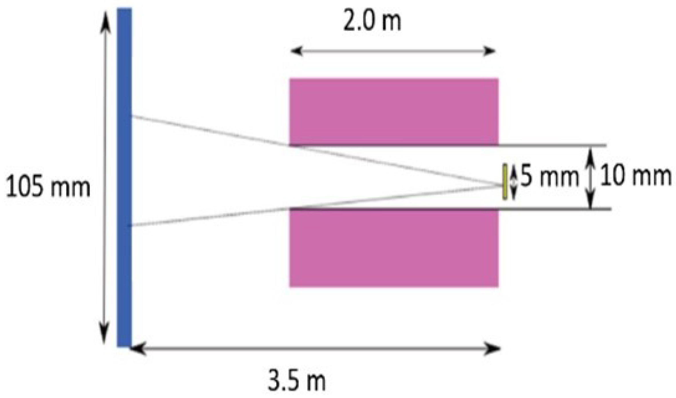
2.2. Multi-Channel Collimator Guide

A multi-channel collimator guide (C) was designed to balance the resolution contributions in FREYJA. The need for such a specific collimator was driven by the spatial restrictions and high radiation environment. This is justified by the fact that the wave vector transfer is determined by
Q = 4 π s i n θ / λ ,
where θ equals the reflection angle, and λ is the wavelength of the neutron; the resolution of the wave vector transfer is determined by (as θ < < 1 )
( Δ Q Q ) 2 = ( Δ θ θ ) 2 + ( Δ λ λ ) 2 .
To match the angular contribution with the wavelength contribution, the angular divergence of the beam must be proportional to the reflection angle. In general, this is realized by using a pair of adjustable collimation slits separated in space.
The design parameters of this multi-channel collimator guide system are presented in Figure 4. The materials chosen are boron nitride (red, Figure 4) and aluminum (blue, Figure 4). The collimator consists (i.e., the design, since it has not been constructed yet) of four channels with different widths and an overall height of 50 mm of boron nitride diaphragms and an aluminum support.
As shown in Figure 4, the entrance aperture for each of the channels of the collimator is smaller than the aluminum support. Hence, all the entrance beam (limited in divergence already by the distance to the source) that can hit the collimator is absorbed by the boron nitride, yielding just easily shielded soft-gamma upon neutron absorption. To make sure also that no scattered neutrons are absorbed in the aluminum, it can be coated with a thin layer of boron rubber, ensuring that the channels remain the same.
The top and bottom walls have m = 5 supermirror coating [17], whereas the sidewalls are absorbing.
The collimated beams are directed towards the center of the sample through the sample slit S2 (Figure 1). For each collimation provided by the appropriate channel of the collimator, it holds that the wavelength spectra of both the incident beam and the reflected beam need to be measured. Although the collimated beams are focused on the sample position, after reflection, the beams are well separated at the detector position, enabling data collection of multiple beams at the same time. Although multiple beam measurements are possible, this has only a limited advantage because the wavelength and angular resolutions can be matched for only one beam, and the increased background due to incoherent or off-specular scattering from the sample surface limits the available reflectivity range.
For the standard mode of operation, however, individual collimated beams corresponding to the required Q-resolution and reflection angle are used. This prevents increased background due to incoherent or off-specular scattering. The other beams are absorbed by an adaptable beam selector (BS, Figure 1) at the beam channel exit made from boron nitride slits with adjustable locations and widths (Table 2).
Table 2 lists results of the analytical and Monte Carlo simulation neutron intensities and count rates at the detector (i.e., maximum expected). Note also that the chopper must be able to be aligned with the direction of the selected beam (this is discussed in the next section).
Figure 5a shows the calculated 1D neutron intensities along the detector for the different collimator channels.The distance between the sample and the surface of the detector was set to 2.4 m, and the width of S2 was set to 0.1 mm to act as a pinhole. The CNS was represented as a homogeneous circular surface. The results show that the intensity in all the channels is similar, with reduced intensity towards the edges due to the circular shape of the source and the rectangular shape of the channels; part of the channel looks around the edges of the source. The effect is estimated to be approximately 10%. The four different lines in Figure 5a show the influence of the coatings on the reflecting surfaces. The coating of the guide containing the FOM only marginally contributes to the intensity on the detector, while the coating on the multi-channel collimator guide gives a yield of approximately 30%.
Monte Carlo (MC) simulations with McStas (McStas code generator 2.4, 26 June 2017, Copyright (C) DTU Physics and Risoe National Laboratory, DK, Additions (C) Institut Laue Langevin, FR) [18] and VITESS (Virtual Instrumentation Tool for the ESS (VITESS) version 3.4, Helmholtz-Zentrum Berlin für Materialien und Energie (HZB), Berlin, DE and Forschungszentrum Jülich, Jülich, DE) [19] software packages (Figure 5b and Table 3) used the source parameters from the resulting measurement with the CNS described in the previous section and Figure 3. For these calculations (i.e., the design of the multi-channel collimator guide), the distance between the beam selector and S2 was 1.9 m, the collimator guide had an m = 5 coating, and the coating of the FOM guide system was omitted. In Figure 5b, the intensity profiles for each beam are shown. The neutron moderator used in these simulations was a sphere of 100 mm diameter. The source spectrum was described by three Maxwellian distributions with characteristic temperatures of 70, 21.5 and 323 K and source intensities of 1.28 × 10 12 , 0.32 × 10 12 and 5 × 10 10 n/s/cm2/sr, respectively. This resulted in a total source strength of 1.6 × 10 12 n/s/cm2/sr.

2.3. Frame Overlap Mirror (FOM)

FREYJA employs a well-defined wavelength band from 2–15 Å in the standard mode of operation (unpolarized). In order to achieve this range of wavelengths, a guide with an integrated V-shaped cavity was designed [20,21,22]. The same guide is also used as a frame overlap mirror (FOM).
Frame overlapping occurs when slow neutrons of a pulse arrive at the detector at the same time as the fast neutrons from the next pulse. The purpose of the FOM is to prevent slow neutrons from the previous TOF frame to be counted in channels of faster neutrons in the current TOF frame. The slower neutrons are reflected out of the beam by the FOM. This reflection plane is perpendicular to the reflection plane of the sample; hence, the cut-off is not influenced by the different collimations. Generally, an additional chopper is used to remove the slowest neutrons from the beam. In the case of FREYJA, however, because of space concerns, a mirror in the guide is used to reflect the slowest neutrons out of the beam. This has the added advantages of being compact and of providing a low-radiation environment, which results in a lowered background signal.
Figure 6 shows the basic design of the assembly as viewed from the top. The guide body is made of aluminum, has a cross section of 50 × 50 mm2, a length of approximately 0.956 m and supermirror coatings (m = 5, reflectivity 72%) at the top and bottom surfaces. The sides are not coated. The FOM is composed of multiple Si wafers with a thickness of 0.3 mm and a waviness of less than 2 × 10 4 rad. This results in high transmission of the selected neutrons. The Si wafers are coated on both sides with nickel (m = 1, reflectivity 99%). The taper angle of the FOM is 1.5 degrees with respect to the optical axis.

2.4. Double−Disk Chopper System
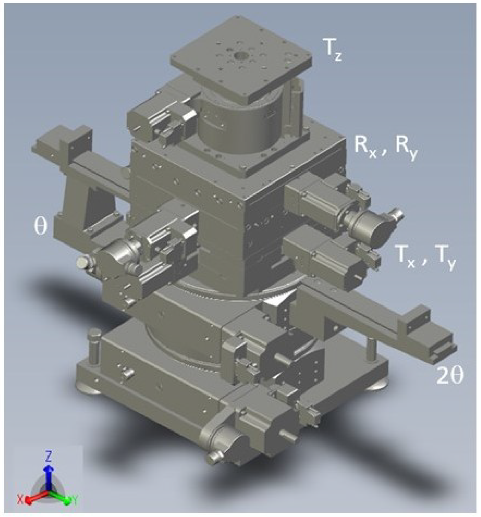
The resolution and intensity aspects of an optimal chopper that matches the resolution contribution due to wavelength spread and angle spread were introduced by Ad van Well [23]. This design is used by the ROG reflectometer [24] in Delft and the EROS reflectometer [25] in Saclay. The FREYJA reflectometer is equipped with a ‘Van Well−type’ double−disk chopper of 157 mm radius, frequency of 35 Hz, two slots per disk, a fixed opening slit window, a variable inter-disk distance and a TOF trigger. The variable inter−disk distance enables tuning of the wavelength resolution ( Δ λ / λ ) within three settings from 6.8% FWHM of a triangular distribution down to 3.4% and 1.7% according to the specific needs of the experiment. A sketch of the chopper system is shown in Figure 7. The characteristic parameters of the chopper system are summarized in Table 4.
The advantage of the ‘Van Well−type’ double−disk chopper is that the wavelength spread Δ λ is proportional to the wavelength λ . This results in a constant wavelength resolution ( Δ λ / λ ) up to a characteristic upper wavelength λ 0 .
To support the alignment of the chopper axis with respect to the neutron beam axis, the height of the chopper system is made adjustable (maximum +/−20 mm) to enable positioning of the chopper opening at the height of the beam. The chopper system enables rotation of the chopper axis by +/−10 mrad in the horizontal plane around the sample location at 1.4 m from the first disk (upstream) of the chopper (Figure 7a). The accuracy corresponds to the chopper axis alignment accuracy.

2.5. Sample Stage

The sample stage facilitates the accurate alignment of the sample, including a possible sample environment. The alignment consists of two tilts to adjust the reflection angle and the beam cross section to the sample horizon and two rotations and XYZ-translations to align sample structures and the detector with the beam. To accommodate different sample environments, the total load capacity of the sample stack should be at least 150 kg. Figure 8 illustrates a possible design for such a stack. The bottom consists of a ( θ 2 θ ) two-circle goniometer. This is followed by translation stages in the X–Y plane. For rotation/tilt along the X–Y direction, two goniometers with sufficient angular range (>±10°) can be employed. To offer the possibility of employing magnetic fields and polarized neutrons, the X–Y and tilt stages should be constructed from low-magnetic materials and contain non-magnetic worm shafts with ceramic coatings. Finally, the Z-stage on top of the stack should contain non-magnetic worm shafts and worm wheels, ceramic bearings and non-magnetic linear guide systems.

2.6. Polarization Option

Normally for reflectometry on magnetic samples, the reflectivity’s R + + , R , R + and R + branches are measured. R + + denotes the reflectivity of the sample when both the incoming and reflected neutron wave have a spin parallel to the magnetic flux direction and R when both the incoming and reflected neutron wave have a spin anti-parallel to the magnetic flux. R + and R + are the reflectivities that include a spin flip. When the sample is magnetized in-plane and the magnetic flux is applied parallel to this plane, no spin flip will occur, and it is sufficient to polarize the beam in front of the sample and flip the spin direction between the polarizer and sample to be able to measure R + + and R . FREYJA’s components for polarization and spin flipping are discussed below.

2.6.1. Polarizer

For reflectometry, polarization is preferably achieved with a degree of polarization above 0.95 and can be obtained by reflection to a magnetic surface [17]. A typical polarizer (for instance, SwissNeutronics, Klingau, Switzerland [20]) consists of a magnetic structure made of Fe/Si layers that take care of the polarization of the beam by reflection in one direction (the beam direction and surface normal to the reflection plane), while the side walls might be Ni/Ti coated just to keep the beam inside the polarizer (both up and down spin) in the direction perpendicular to the reflection plane. A neutron absorber is placed around the SM, and a coarse neutron-absorbing mask or even a slit can be placed after the SM to clean out the beam. The useful range of the supermirror (SM) is in the wave vector transfer range of 0.015 Å−1 to 0.12 Å−1. For good polarization at a maximum wavelength of 10 Å, the incident angle of the polarizing SM should be 0.68°.

2.6.2. Spin Flipper

A radio-frequency spin flipper was selected because of the wavelength range needed and the limited space available. For such flippers, it is best not to have wires in the beam. Note that these flippers use a gradient field and, hence, can also work for a white beam. The beam length needed for such spin flippers is approximately 0.2 m. The distance between the polarizer and the spin flipper depends on the fall-off of the guide field to the polarizer. This can be slightly manipulated by design. Here, values for a typical polarizer were used, i.e., about 0.2 m. Monte Carlo simulations using the VITESS (Virtual Instrumentation Tool for the ESS (VITESS) version 3.4, Helmholtz-Zentrum Berlin für Materialien und Energie (HZB), Berlin, DE and Forschungszentrum Jülich, Jülich, DE) software package polarization modules [19] with a standard polarization configuration are presented in Figure 9. The modules used in the simulations were p o l _ m i r r o r and f l i p p e r _ g r a d i e n t (before and after the sample position).
The module p o l _ m i r r o r simulates one plane mirror that might have different reflectivity curves for spin-up and spin-down neutrons. A transmitted or reflected beam can be considered. The coordinate system of the following module must be set accordingly (parameters listed in Table 5) [20,21].
The module f l i p p e r _ g r a d i e n t simulates spin precessions in the magnetic field. The first part of such a field is a rotating magnetic field. The amplitude of this field must change by a sinus distribution with a semi-period, which is equal to the appropriate dimensions of the rotating field volume. A permanent value of the amplitude can also be given. The second part of the general field is a guide magnetic field [19].
The full parameter list used is described in Table 5.

2.7. Detector System

To obtain a constant relative wave vector resolution of Δ Q Q , the relative angle resolution of a detector system should be Δ Q Q / 2 ; hence, Δ θ θ = Δ Q Q / 2 . This is determined by the slit width of the diaphragms defining the incident beam d 1 at a distance L 12 from the detector with pixel resolution d 2 . The angular distribution function of a double−slit system is trapezium shaped. The actual full width at half maximum (FWHM) is given by d 1 / L 12 if d 1 > d 2 or is d 2 / L 12 otherwise. Here, the FWHM of the Gaussian distribution with the same standard deviation is used:
Δ θ = l n 2 3 d 1 2 + d 2 2 L 12 2 = Δ Q Q θ 2 .
The optimal resolution intensity performance is obtained when d 1 = d 2 ; hence,
d 1 = Δ Q Q θ L 12 3 4 ln 2 Δ Q Q θ L 12
For a sample-to-detector distance of 2.4 m, the needed detector pixel sizes are given in Table 6.
To check these results, the reflection curves of a sample were simulated for the different Q-resolutions using the position sensitive detector (PSD) spatial resolution and a reflection angle of 20 mrad. L 12 was taken as 4.2 m. The intensity of each detector pixel was determined by means of a summation of the neutrons that would reach the detector pixel after passing through the chopper and the first slit in a 60 s measurement. The coherent summing method [26] was used to obtain the best Q-resolution from the PSD results. The chopper resolution and angular resolution contributions were matched. The sample used was a natural nickel layer of 50 nm thickness on top of a silicon substrate. The results are shown in Figure 10. The red curve is the theoretical reflection without a resolution contribution. The black curve is the theoretical curve folded with a Gaussian distribution function with an FWHM equal to the Q-resolution used. It is clear that the simulated reflectivity corresponds to the black curves, indicating the correctness of the assumed PSD resolution.
The pixel size of the detector for FREYJA needs to be better than 0.6 mm (see Table 6) to access all but one of the desired Q-resolution settings. Wavelength-shifting fiber (WSF) detectors—recently employed at ISIS—or the boron-10 multi-blade detector [27] designed for the ESTIA and FREIA reflectometers at the ESS are then possible candidates [28,29]. A suitable 10B multi-blade detector for the present case could have an active area of 200 × 260 mm2 and individual cassettes containing 32 wires and 64 strips. To ease the process of sample alignment, part of the detector (e.g., 25% of the area or 100 × 130 mm2) could be used in 2D mode with the resolution optimized for this purpose. The targeted spatial resolution for FREYJA would then be 0.5 mm along the wire direction and about 3.5 mm along the strip direction.

3. Conclusions

An overview of the design parameters of a new concept for a time-of-flight (TOF) neutron reflectometer FREYJA is given. The instrument is based on a chopper system with some unique features. Due to tight spatial restrictions and the need to avoid moving parts inside the test beam channel, a multi-channel collimator guide is implemented that allows easy selection of one out of three different Q-resolutions. The specific Q-resolution used in a particular case depends on the properties of the sample under investigation. The performance was calculated analytically and confirmed by Monte Carlo simulations. The design considerations made here are highly relevant for neutron sources where space is limited or where the instrument components are in a high-radiation environment.

Author Contributions

Conceptualization, R.-V.E. and C.F.; Formal analysis, R.-V.E., V.-O.d.H., C.F. and K.D.K.; Methodology, R.-V.E., V.-O.d.H., C.F. and K.D.K.; Project administration, B.C.H.; Software, R.-V.E., V.-O.d.H., C.F., K.D.K. and I.L.-J.; Supervision, B.C.H.; Validation, R.-V.E., V.-O.d.H., C.F., K.D.K. and I.L.-J.; Writing—original draft, R.-V.E. and C.F.; Writing—review and editing, R.-V.E., V.-O.d.H., C.F., K.D.K., I.L.-J. and B.C.H. All authors have read and agreed to the published version of the manuscript.

Funding

This research was funded by The Research Council of Norway, grant number 245942—Norwegian Center for Neutron Research [11].

Data Availability Statement

The original contributions presented in the study are included in the article, further inquiries can be directed to the corresponding author.

Acknowledgments

The Research Council of Norway is acknowledged for financial support. We are grateful for the professional assistance offered by the staff at the JEEP II reactor and Mirrotron during the experimental and test measurements performed at the former JEEP II reactor neutron beamlines. This work was invited to be included in the CYCLEUR framework collaboration, opening up further applications for cyclotrons and future compact neutron sources.

Conflicts of Interest

Author Victor-Otto de Haan was employed by the company BonPhysics B.V. The remaining authors declare that the research was conducted in the absence of any commercial or financial relationships that could be construed as a potential conflict of interes.

References

  1. IAEA. Compact Accelerator Based Neutron Sources; TECDOC Series 1981; International Atomic Energy Agency: Vienna, Austria, 2021; Available online: https://www.iaea.org/publications/14948/compact-accelerator-based-neutron-sources (accessed on 1 December 2023).
  2. World Nuclear Association, Website. 2024. Available online: https://www.world-nuclear.org/information-library/non-power-nuclear-applications/radioisotopes-research/research-reactors.aspx (accessed on 1 March 2024).
  3. Hayter, J.; Penfold, J.; Williams, W. Observation of the interference of neutrons reflected from thin films. Nature 1976, 262, 569–570. [Google Scholar] [CrossRef]
  4. Stahn, J.; Glavic, A. Focusing neutron reflectometry: Implementation and experience on the TOF-reflectometer Amor. Nucl. Instrum. Methods Phys. Res. Sect. Accel. Spectrometers Detect. Assoc. Equip. 2016, 821, 44–54. [Google Scholar] [CrossRef]
  5. Daillant, J.; Gibaud, A. X-ray and Neutron Reflectivity: Principles and Applications. In Lecture Notes in Physics; Monographs 58; Springer: Berlin/Heidelberg, Germany; New York, NY, USA, 1999. [Google Scholar]
  6. Ott, F. Neutron reflectivity. In Surface Science Techniques; Springer: Berlin/Heidelberg, Germany, 2013; pp. 307–332. Available online: https://link.springer.com/chapter/10.1007/3-540-48696-8_5 (accessed on 1 March 2024).
  7. Mayes, M.; Jagadamma, S.; Ambaye, H.; Petridis, L.; Lauter, V. Neutron reflectometry reveals the internal structure of organic compounds deposited on aluminum oxide. Geoderma 2013, 192, 182–188. [Google Scholar] [CrossRef]
  8. Björck, M.; Andersson, G. GenX: An extensible X-ray reflectivity refinement program utilizing differential evolution. J. Appl. Cryst. 2007, 40, 1174–1178. [Google Scholar] [CrossRef]
  9. Williams, W.G. Polarized Neutrons; Series on Neutron Scattering in Condensed Matter; Clarendon Press: Oxford, UK, 1988; ISBN 9780198510055. [Google Scholar]
  10. Felici, R.; Penfold, J.; Ward, R.C.; Williams, W.G. A polarised neutron reflectometer for studying surface magnetism. Appl. Phys. A 1988, 45, 169–174. [Google Scholar] [CrossRef]
  11. NcNeutron. 2023. Available online: https://ife.no/en/project/ncneutron-norwegian-center-for-neutron-research (accessed on 15 April 2024).
  12. Saerbeck, T.; Cortie, D.L.; Brück, S.; Bertinshaw, J.; Holt, S.A.; Nelson, A.; James, M.; Lee, W.T.; Klose, F. Time-of-flight polarized neutron reflectometry on PLATYPUS: Status and future developments. Phys. Procedia 2013, 42, 213–217. [Google Scholar] [CrossRef]
  13. Mirrotron Ltd., Budapest, Hungary. Available online: https://mirrotron.com/en (accessed on 30 March 2024).
  14. de Haan, V.-O.; Knudsen, K.D. Application of a two-phase thermosyphon loop calculation method to a cold neutron source. Cryogenics 2019, 97, 55–62. [Google Scholar] [CrossRef]
  15. de Haan, V.-O.; Gommers, R.; Rowe, J.M. Thermodynamic calculations of a two-phase thermosyphon loop for cold neutron sources. Cryogenics 2017, 85, 30–43. [Google Scholar] [CrossRef]
  16. Hirakawa, N.; Nara, H.; Iwasaki, T.; Matsuyama, S.; Tsujimoto, K.; Kobayashi, K.; Kudoh, K. Measurement and Analysis of Cadmium Ratios of Activation Foils in Thermal Critical Assembly (KUCA B 3/8”P36EU-NU-EU). J. Nucl. Sci. Technol. 1993, 30, 628–637. [Google Scholar] [CrossRef]
  17. Mezei, F. Novel Polarized Neutron Devices: Supermirror and Spin Component Amplifier. Communications on Physics 1. 1976, pp. 81–85. Available online: https://www.ill.eu/fileadmin/user_upload/ILL/4_Neutrons_for_society/neutron-technology/pdfs/optics/comm-on-phys-sm-1.pdf (accessed on 19 March 2024).
  18. Willendrup, P.; Farhi, E.; Knudsen, E.; Filges, U.; Lefmann, K. McStas: Past, present and future. J. Neutron Res. 2014, 17, 35–43. [Google Scholar] [CrossRef]
  19. Lieutenant, K.; Zendler, C.; Manoshin, S.; Fromme, M.; Houben, A.; Nekrassov, D. VITESS 2.10-Virtual instrumentation tool for the European Spallation Source. J. Neutron Res. 2014, 17, 45–51. [Google Scholar] [CrossRef]
  20. SwissNeutronics, AG, Bruehlstrasse 28, CH-5313 Klingnau, Switzerland AG. 2024. Available online: https://www.swissneutronics.ch (accessed on 16 April 2024).
  21. Schanzer, C.; Schneider, M.; Böni, P. Neutron Optics: Towards Applications for Hot Neutrons. J. Phys. Conf. Ser. 2016, 746, 012024. [Google Scholar] [CrossRef]
  22. Gainov, R.R.; Mezei, F.; Füzi, J.; Russina, M. Design concepts for a supermirror V-cavity based combined beam polarizer and compressor system for the upgraded neutron time-of-flight spectrometer NEAT. Nucl. Instruments Methods Phys. Res. Sect. Accel. Spectrometers Detect. Assoc. Equip. 2019, 930, 42–48. [Google Scholar] [CrossRef]
  23. van Well, A.A. Double-disk chopper for neutron time-of-flight experiments. Phys. B Phys. Condens. Matter. 1992, 180–181, 959–961. [Google Scholar] [CrossRef]
  24. van Well, A.A.; de Haan, V.O.; Fredrikze, H. ROG, the new neutron reflectometer at IRI, Delft. Phys. B Phys. Condens. Matter. 1994, 198, 217–219. [Google Scholar] [CrossRef]
  25. Cousin, F.; Ott, F.; Gibert, F.; Menelle, A. EROS II: A boosted time-of-flight reflectometer for multi-purposes applications at the Laboratoire Léon Brillouin. Eur. Phys. J. Plus. 2011, 126, 109. [Google Scholar] [CrossRef]
  26. Cubitt, R.; Saerbeck, T.; Campbell, R.A.; Barker, R.; Gutfreund, P. An improved algorithm for reducing reflectometry data involving divergent beams or non-flat samples. J. Appl. Cryst. 2015, 48, 2006–2011. [Google Scholar] [CrossRef]
  27. Mauri, G.; Apostolidis, I.; Christensen, M.J.; Glavic, A.; Lai, C.C.; Laloni, A.; Messi, F.; Olsson, A.L.; Robinson, L.; Stahn, J.; et al. The Multi-Blade Boron-10-based neutron detector performance using a focusing reflectometer. J. Instrum. 2020, 15, P03010. [Google Scholar] [CrossRef]
  28. Stahn, J.; Glavic, A. Efficient polarization analysis for focusing neutron instruments. J. Phys. Conf. Ser. 2017, 862, 012007. [Google Scholar] [CrossRef]
  29. Glavic, A.; Stahn, J.; Schütz, S. Estia: Design of the polarized, small sample reflectometer at ESS. Swiss Neutron News 2016, 48, 6–16. [Google Scholar]
Figure 1. Position of FREYJA’s major components along the beamline. CNS: cold neutron source, SF: sapphire filter, SP: steel plug, C: collimator, FOM: frame overlap mirror, SH: shutter, BS: beam selector, CH: chopper and shielding, POL: polarization option, S2: sample slit, SS: sample stage, FT: flight tube, DET: detector and B: beam stop.
Instruments 08 00030 g001
Figure 2. Sketch of the gold foil measurement geometry. From left to right; CNS, collimator and foil. The figure is not to scale in order to better illustrate the different parts.
Instruments 08 00030 g002
Figure 3. Neutron flux distribution as measured (black) and after corrections for detector efficiency (red) and air attenuation (blue). Also shown is the fit to a Maxwell–Boltzmann distribution (green) combining the two temperature contributions T = 20 K and T = 70 K.
Instruments 08 00030 g003
Figure 4. Design of the multi-channel collimator guide body using the boron nitride diaphragms (top view, dimensions in mm).
Instruments 08 00030 g004
Figure 5. (a) The 1D neutron intensity along the detector. The different lines represent different coatings on the reflecting surface of the collimator (G1) and the FOM guide system (G2). (b) Monte Carlo simulations of the 4 channels of the multi-channel collimator guide using McStas, ( 10 10 ) traces.
Instruments 08 00030 g005
Figure 6. Top view of the FOM assembly, which provides a well-defined wavelength band of 2–15 Å.
Instruments 08 00030 g006
Figure 7. (a) Chopper system alignment in horizontal plane. (b) Preliminary sketch of a ‘Van Well chopper’ system.
Instruments 08 00030 g007
Figure 8. Seven-axis sample stack consisting of ( θ 2 θ ) goniometer; X,Y translation; X,Y rotation/tilt and Z-stage (from bottom to top).
Instruments 08 00030 g008
Figure 9. Monte Carlo simulation for neutron spin precession using f l i p p e r _ g r a d i e n t module for polarized configuration of FREYJA (wavelength range 2.5–10 Å) with VITESS software package.
Instruments 08 00030 g009
Figure 10. Reflectivity curves for 2.5%, 5.0% and 10% Q-resolution (from left to right). Red: theoretical curve without resolution contribution. Black: theoretical curve folded with a Gaussian distribution function with an FWHM equal to the Q-resolution. Reflection angle 20 mrad. Horizontal axis: Q / Q c .
Instruments 08 00030 g010
Table 1. The neutron reflectometer instrument parameters.
Instrument TypeCold-Neutron TOF Reflectometer
Scattering geometryHorizontal (sample surface vertical)
Instrument length8.3 m (source–detector)
4.0 m (chopper–detector)
2.4 m (sample–detector)
Wavelength range 12–15 Å (unpolarized)
2.5–10 Å (polarized)
Flux at sample 5 × 10 5 n/s/cm2
Typical resolution settings ( Δ Q / Q ) = 2.5, 5, 10 %
Q-range0.004–0.22 Å−1 ( θ = 0.3 and 2.0 deg) extendable up to 0.35 Å−1 ( θ = 3.5 deg)
Attainable reflectivity
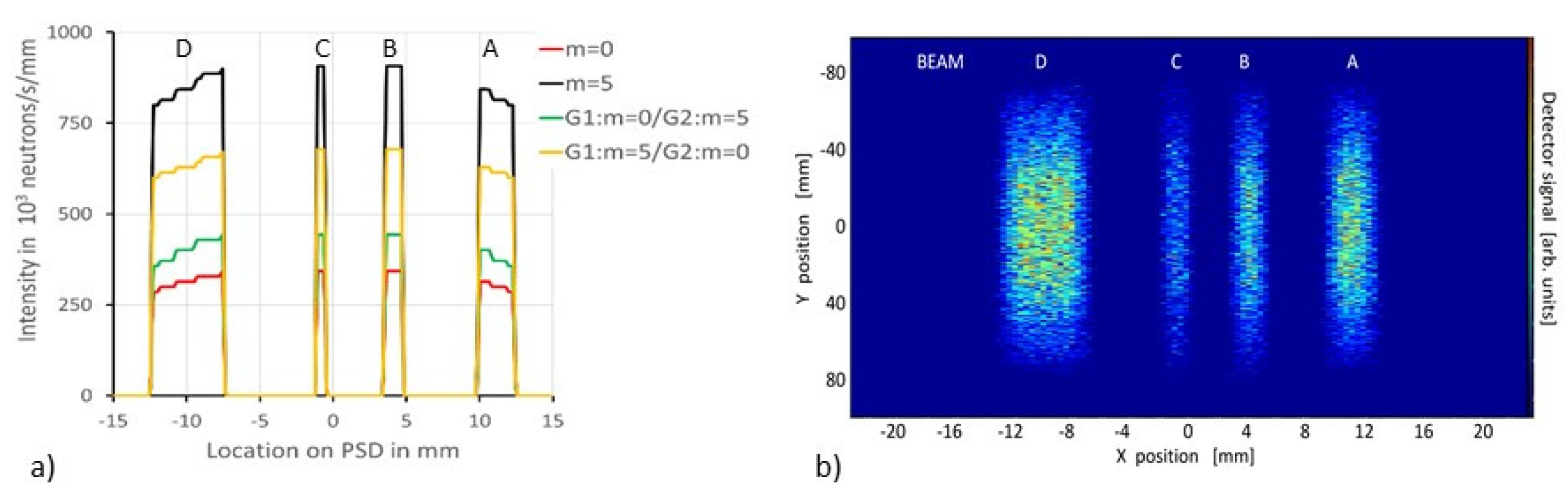
 ( 10 5 )
1 Wavelength range is set by a FOM in unpolarized mode and by a polarizing supermirror in polarized mode.
Table 2. Maximum intensity on detector and maximal count rate for each beam.
BeamAngle (mrad)Pixel Size (mm)Beam Selector (BS) Offset from Optical Axis (mm)Beam Selector (BS) Width (mm)Max Intensity × 10 6 n/s/cm2Count Rate
(×106 n/s)
A−4.292.4−8.14.09.9061.06
B−1.591.2−3.02.04.9816.77
C+0.320.60.61.02.484.24
D+3.814.87.28.019.9251
Table 3. Comparison of MC simulation results (McStas and VITESS) with analytical calculations for the expected count rates at the sample position for the four individual beams denoted A–D.
Beam IdentifierBeam Width and Sample Slit Size (mm)Total Neutron Count Rate at Sample Position ( n / s )
AnalyticalMcStasVITESS
A4 6.11 × ( 10 7 ) 5.94 × ( 10 7 ) 5.06 × ( 10 7 )
B2 1.67 × ( 10 7 ) 1.61 × ( 10 7 ) 1.38 × ( 10 7 )
C1 4.24 × ( 10 6 ) 4.04 × ( 10 6 ) 3.21 × ( 10 6 )
D8 2.51 × ( 10 8 ) 2.43 × ( 10 8 ) 2.34 × ( 10 8 )
Table 4. Chopper parameters for several resolution settings; z o is the inter-disk separation, and L T O F is the time-of-flight length calculated from the middle of both disks to the detector surface.
Q-resolution2.5%5.0%10.0%
Wavelength resolution
(FWHM triangular)
1.7%3.4%6.8%
Maximum wavelength 15 Å
Minimum wavelength 2 Å
Disk radius 157.5 mm
Slot height 50 mm
Sector opening 36.4 degrees
z 0 98.8 mm195 mm381 mm
L T O F 3.95 m3.90 m3.81 m
Maximum frequency71.5 Hz72.4 Hz74.2 Hz
Operating frequency 70 Hz (35 Hz assuming 2 slots per disk, 180 degrees apart)
Timing accuracy Δ t 24 μ s48 μ s96 μ s
Table 5. Parameter description of the values used in the VITESS modules for the Monte Carlo simulations.
VITESS ModuleParameters
p o l _ m i r r o r Reflectivity curve R(Q) for spin-up neutrons used m = 5; reflectivity curve R (Q) for spin-down neutrons used m = 7, length 40 cm, width 5 cm, center position 20 cm, inclination 0.75 deg, analysis for OZ direction, output OZ at 40 cm
f l i p p e r _ g r a d i e n t Dimensions 10 cm × 10 cm × 10 cm, number of domains 1000× direction, 500 y-direction, 500 z-direction, magnetic field amplitude 15 Oe, rotation frequency −288,723.6 Hz, permanent/initial value of the Z component of the guide magnetic field 84 Oe
Table 6. Detector pixel sizes in mm as function of reflection angle and required Q-resolution for a sample-to-detector distance of 2.4 m.
Q Resolution FWHM θ mrad
51020
2.5%0.300.601.20
5%0.601.202.40
10%1.202.404.80
Disclaimer/Publisher’s Note: The statements, opinions and data contained in all publications are solely those of the individual author(s) and contributor(s) and not of MDPI and/or the editor(s). MDPI and/or the editor(s) disclaim responsibility for any injury to people or property resulting from any ideas, methods, instructions or products referred to in the content.

