
Fully-Programmable, Low-Cost, “Do-It-Yourself” Pressure Source for General Purpose Use in the Microfluidic Laboratory


Abstract
:
1. Introduction
2. Materials and Methods
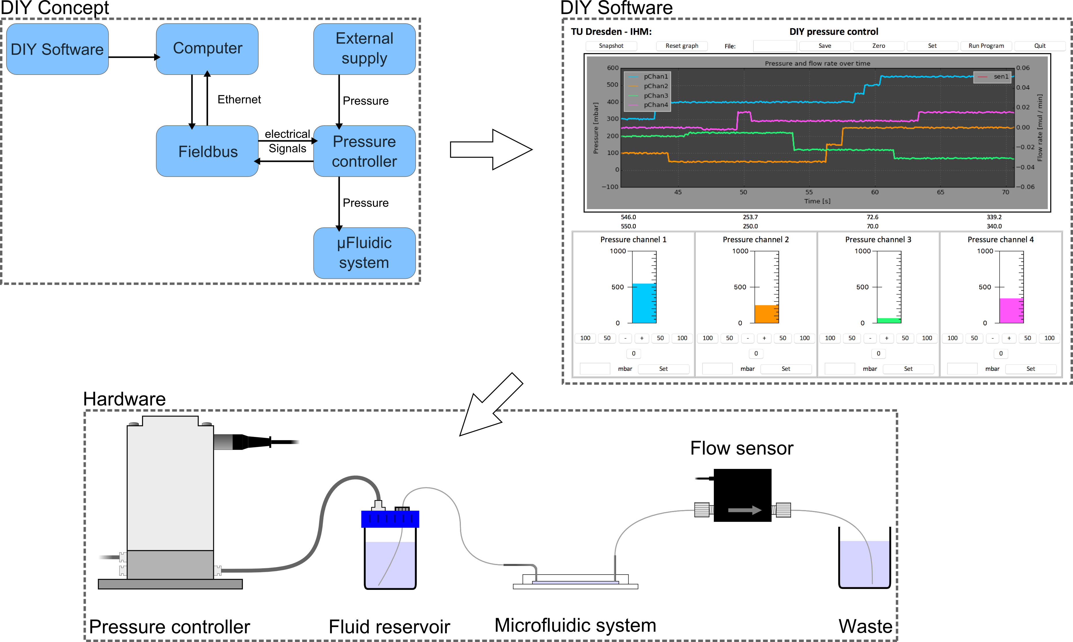
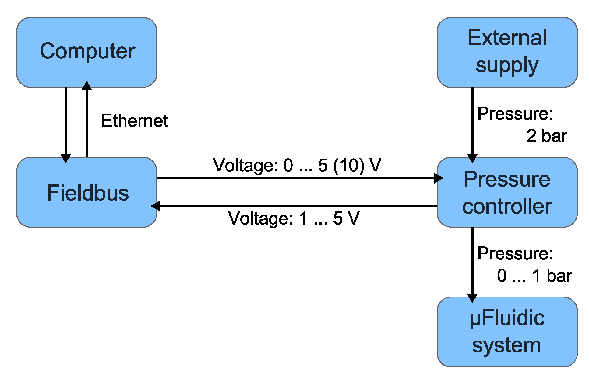
2.1. Concept
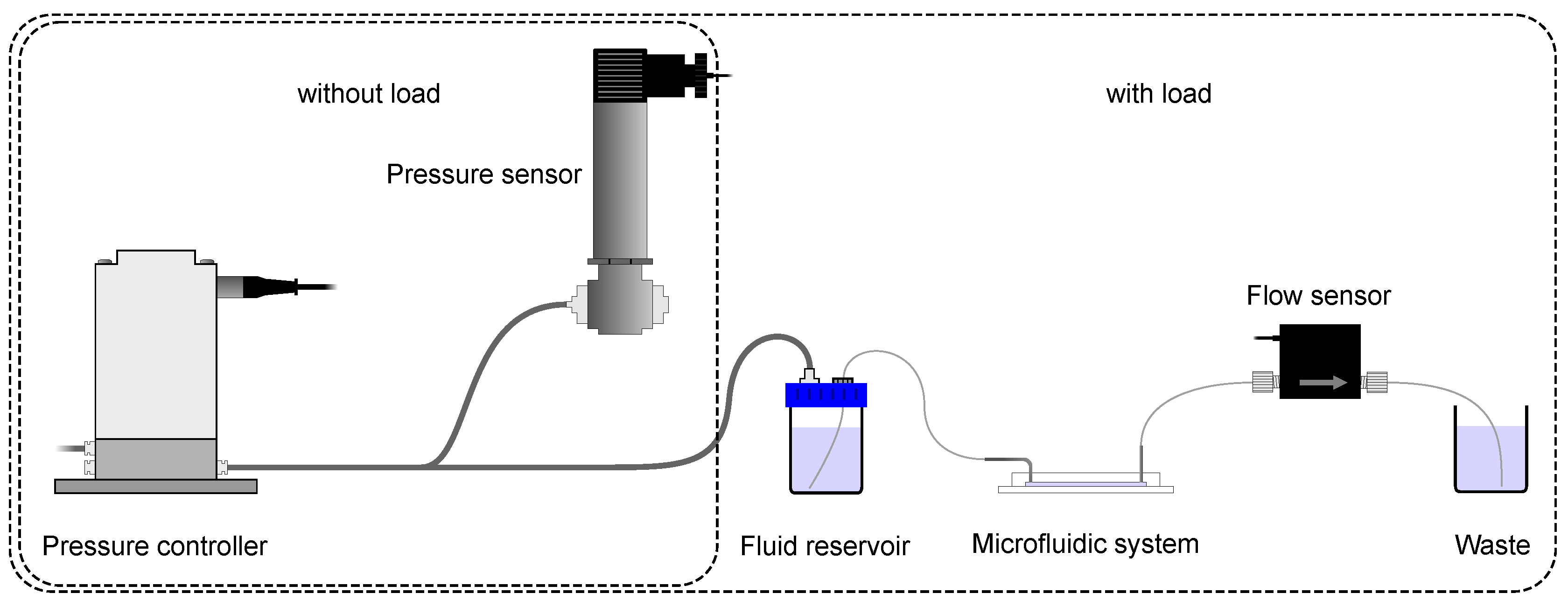
2.2. Characterization Setup
2.3. Microfluidic Chip System
2.3.1. Master Fabrication
2.3.2. Chip Fabrication
2.3.3. Droplet Experiment
3. Results
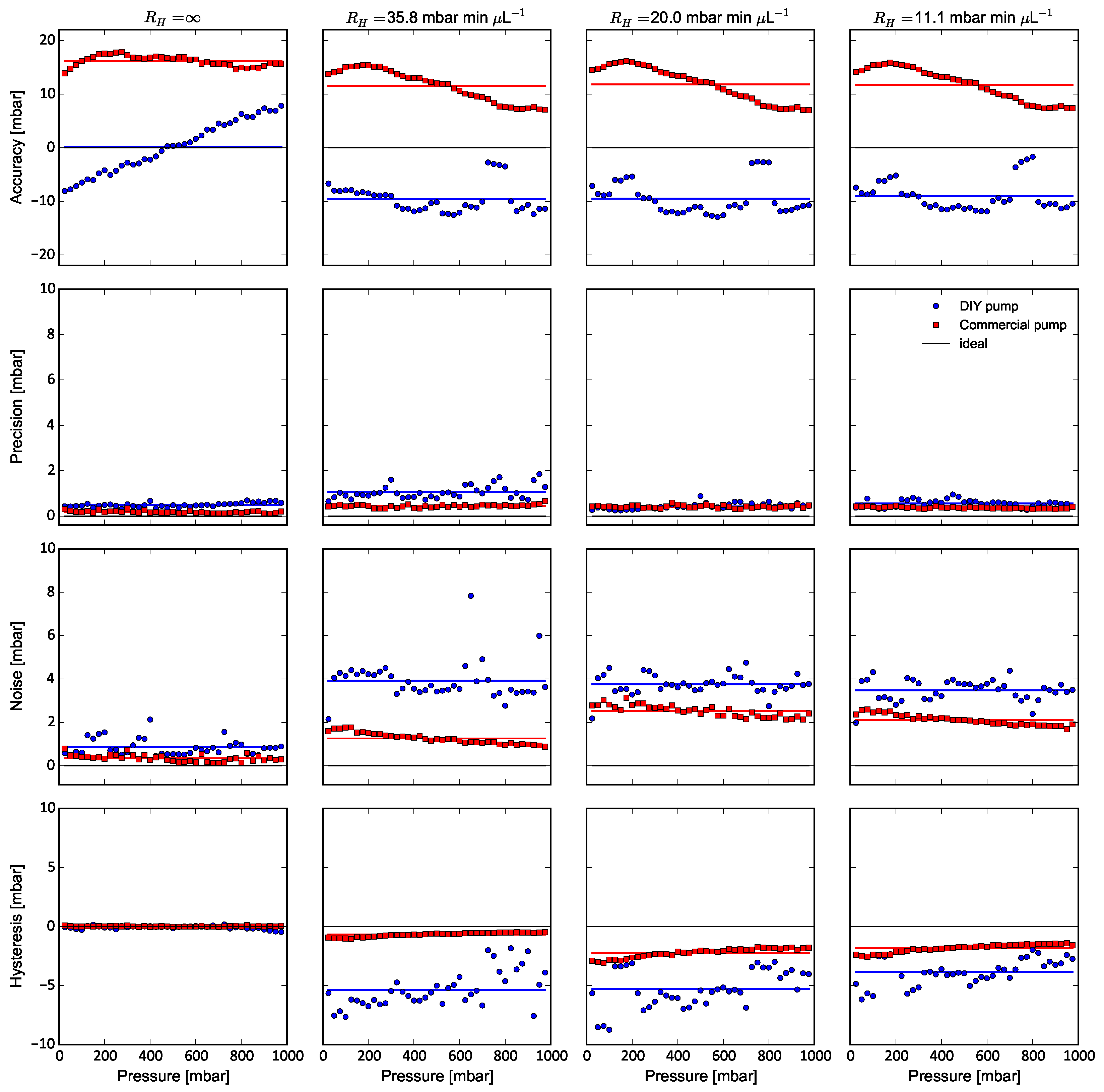
3.1. DIY System Performance
3.1.1. Accuracy
3.1.2. Precision
3.1.3. Noise
3.1.4. Hysteresis
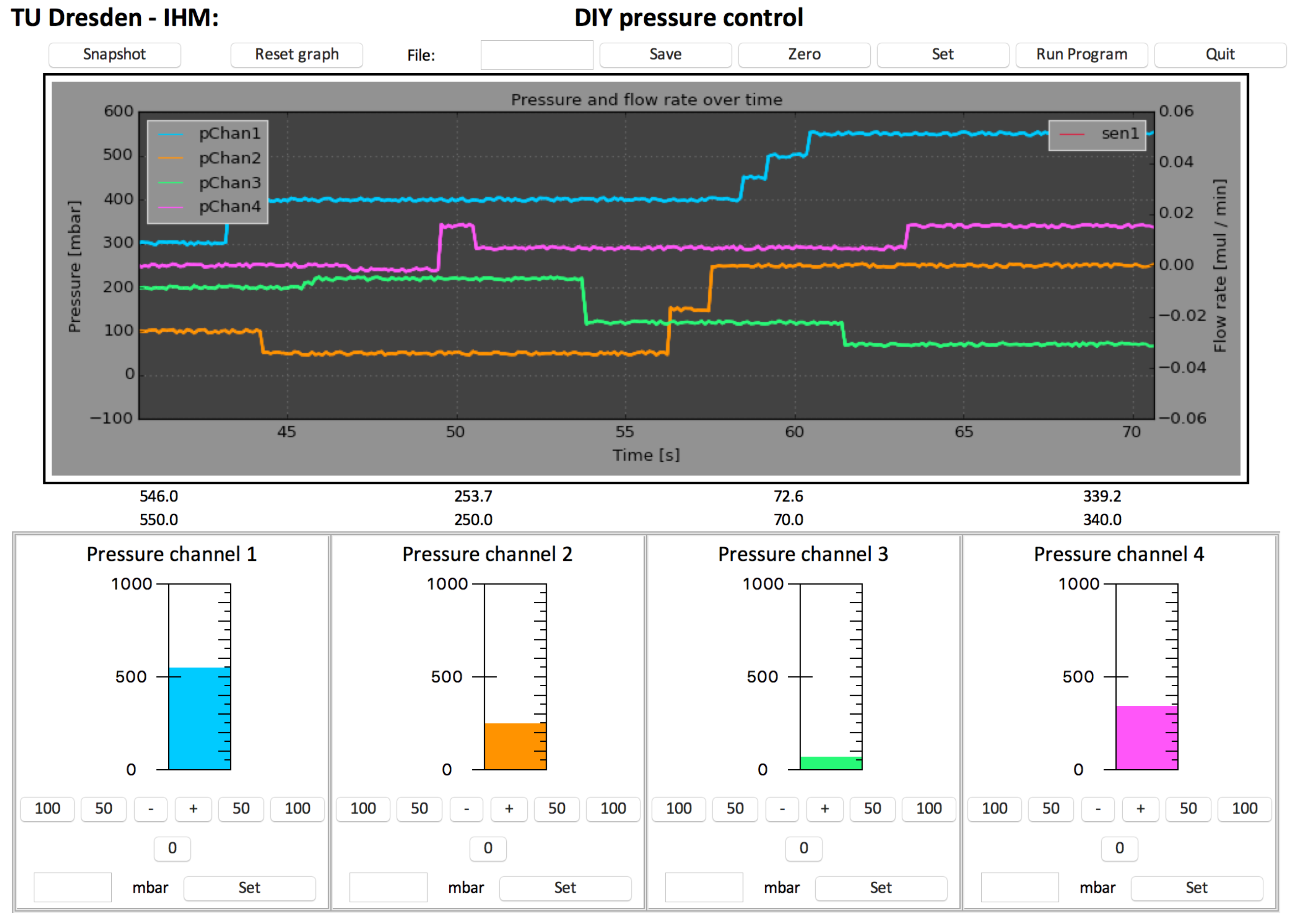
3.2. DIY System GUI
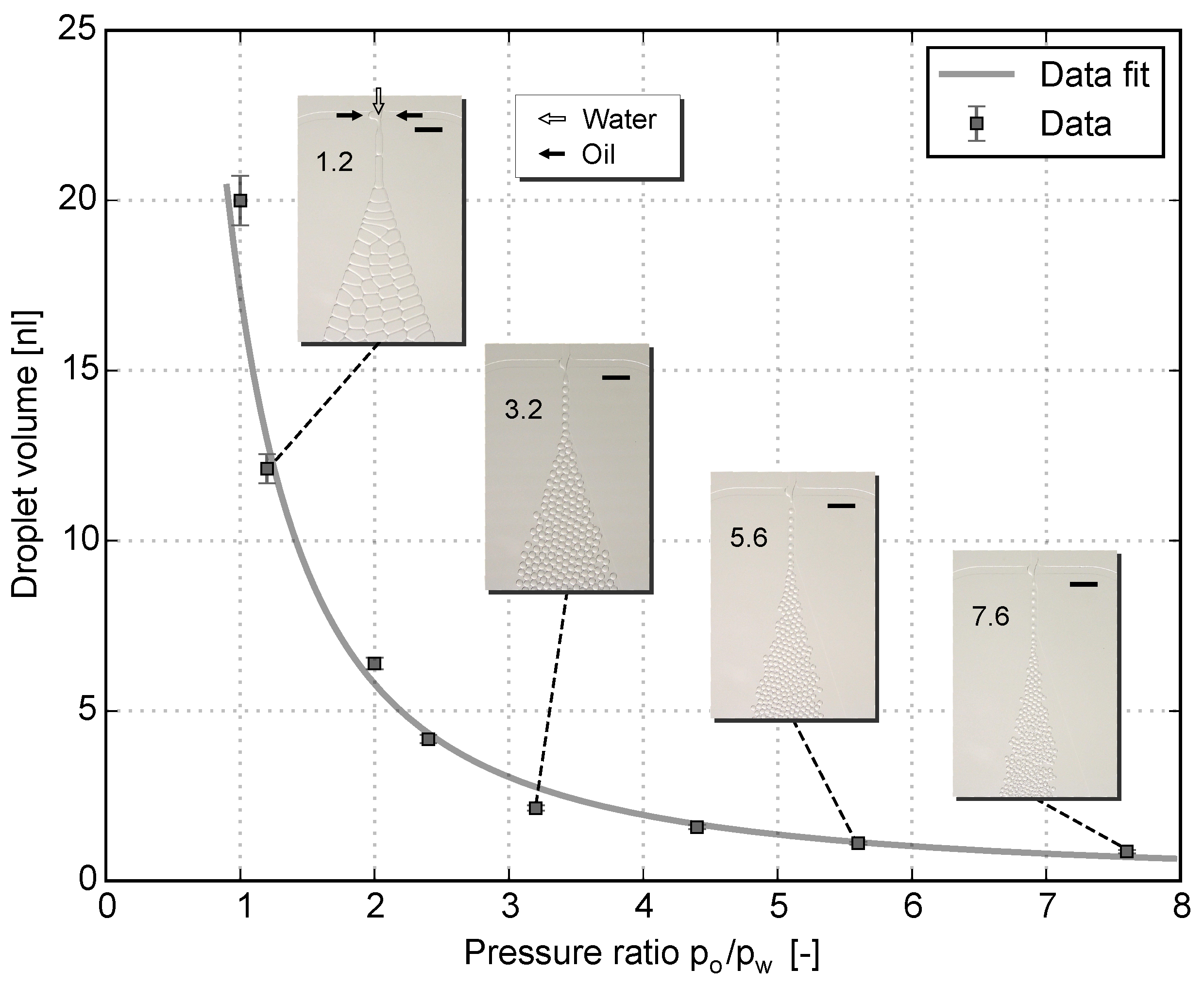
3.3. Droplet Generation
4. Conclusions
4.1. Fields of Applications
4.2. Costs
Supplementary Materials
Acknowledgments
Author Contributions
Conflicts of Interest
Abbreviations
| DIY | Do It Yourself |
| DFR | Dry Film Resist |
References
- Schulte, T.H.; Bardell, R.L.; Weigl, B.H. Microfluidic technologies in clinical diagnostics. Clin. Chim. Aacta 2002, 321, 1–10. [Google Scholar] [CrossRef]
- Breslauer, D.N.; Lee, P.J.; Lee, L.P. Microfluidics-based systems biology. Mol. Biosyst. 2006, 2, 97–112. [Google Scholar] [CrossRef] [PubMed]
- Yager, P.; Edwards, T.; Fu, E.; Helton, K.; Nelson, K.; Tam, M.R.; Weigl, B.H. Microfluidic diagnostic technologies for global public health. Nature 2006, 442, 412–418. [Google Scholar] [CrossRef] [PubMed]
- Feng, X.; Du, W.; Luo, Q.; Liu, B.F. Microfluidic chip: Next-generation platform for systems biology. Anal. Chim. Aacta 2009, 650, 83–97. [Google Scholar] [CrossRef] [PubMed]
- Salieb-Beugelaar, G.B.; Simone, G.; Arora, A.; Philippi, A.; Manz, A. Latest developments in microfluidic cell biology and analysis systems. Anal. Chem. 2010, 82, 4848–4864. [Google Scholar] [CrossRef] [PubMed]
- Xia, Y.N.; Whitesides, G.M. Soft lithography. Annu. Rev. Mater. Sci. 1998, 37, 551–575. [Google Scholar]
- Kim, P.; Kwon, K.W.; Park, M.C.; Lee, S.H.; Kim, S.M.; Suh, K.Y. Soft lithography for microfluidics: A review. Biochip J. 2008, 2, 1–11. [Google Scholar]
- Unger, M.A.; Chou, H.P.; Thorsen, T.; Scherer, A.; Quake, S.R. Monolithic microfabricated valves and pumps by multilayer soft lithography. Science 2000, 288, 113–116. [Google Scholar] [CrossRef] [PubMed]
- Fordyce, P.M.; Diaz-Botia, C.A.; DeRisi, J.L.; Gomez-Sjoberg, R. Systematic characterization of feature dimensions and closing pressures for microfluidic valves produced via photoresist reflow. Lab Chip 2012, 12, 4287–4295. [Google Scholar] [CrossRef] [PubMed]
- Frank, P.; Haefner, S.; Paschew, G.; Richter, A. Rounding of negative dry film resist by diffusive backside exposure creating rounded channels for pneumatic membrane valves. Micromachines 2015, 6, 1588–1596. [Google Scholar] [CrossRef]
- Duffy, D.C.; McDonald, J.C.; Schueller, O.J.A.; Whitesides, G.M. Rapid prototyping of microfluidic systems in poly(dimethylsiloxane). Anal. Chem. 1998, 70, 4974–4984. [Google Scholar] [CrossRef] [PubMed]
- Vulto, P.; Glade, N.; Altomare, L.; Bablet, J.; Tin, L.D.; Medoro, G.; Chartier, I.; Manaresi, N.; Tartagni, M.; Guerrieri, R. Microfluidic channel fabrication in dry film resist for production and prototyping of hybrid chips. Lab Chip 2005, 5, 158–162. [Google Scholar] [CrossRef] [PubMed]
- Paul, D.; Pallandre, A.; Miserere, S.; Weber, J.; Viovy, J.L. Lamination-based rapid prototyping of microfluidic devices using flexible thermoplastic substrates. Electrophoresis 2007, 28, 1115–1122. [Google Scholar] [CrossRef] [PubMed]
- Stephan, K.; Pittet, P.; Renaud, L.; Kleimann, P.; Morin, P.; Ouaini, N.; Ferrigno, R. Fast prototyping using a dry film photoresist: Microfabrication of soft-lithography masters for microfluidic structures. J. Micromech. Microeng. 2007, 17, N69–N74. [Google Scholar] [CrossRef]
- Takao, H.; Ishida, M. Microfluidic integrated circuits for signal processing using analogous relationship between pneumatic microvalve and MOSFET. J. Microelectromech. Syst. 2003, 12, 497–505. [Google Scholar] [CrossRef]
- Oh, K.W.; Lee, K.; Ahn, B.; Furlani, E.P. Design of pressure-driven microfluidic networks using electric circuit analogy. Lab Chip 2012, 12, 515. [Google Scholar] [CrossRef] [PubMed]
- Perdigones, F.A.; Luque, A.; Quero, J.M. Correspondence between electronics and fluids in mems: Designing microfluidic systems using electronics. IEEE Trans. Ind. Electron. 2014, 8, 6–17. [Google Scholar] [CrossRef]
- Wijnen, B.; Hunt, E.J.; Anzalone, G.C.; Pearce, J.M. Open-source syringe pump library. PLoS ONE 2014, 9, e107216. [Google Scholar] [CrossRef] [PubMed]
- Damase, T.R.; Stephens, D.; Spencer, A.; Allen, P.B. Open source and DIY hardware for DNA nanotechnology labs. J. Biol. Methods 2015, 2, e24. [Google Scholar] [CrossRef] [PubMed]
- Hong, S.M.; Kim, S.H.; Kim, H.J.; Hwang, H.I. Hydrophilic surface modification of PDMS using atmospheric RF plasma. J. Phys. Conf. Ser. 2006, 34, 656–661. [Google Scholar] [CrossRef]
- Thompson, C.S.; Abate, A.R. Adhesive-based bonding technique for PDMS microfluidic devices. Lab Chip 2013, 13, 632. [Google Scholar] [CrossRef] [PubMed]


| Accuracy | Precision | Noise | Hysteresis | ||||||
|---|---|---|---|---|---|---|---|---|---|
| Mean | STD | Mean | STD | Mean | STD | Mean | STD | ||
| Unit: | mbar min L | mbar | mbar | mbar | mbar | mbar | mbar | mbar | mbar |
| ∞ | 0.16 | 4.81 | 0.49 | 0.09 | 0.85 | 0.38 | −0.08 | 0.14 | |
| DIY | 35.8 | −9.55 | 2.65 | 1.06 | 0.29 | 3.92 | 0.89 | −5.36 | 1.53 |
| 20.0 | −9.51 | 3.03 | 0.43 | 0.13 | 3.75 | 0.46 | −5.31 | 1.58 | |
| 11.0 | −9.00 | 2.79 | 0.56 | 0.15 | 3.47 | 0.49 | −3.82 | 1.11 | |
| ∞ | 16.15 | 0.98 | 0.18 | 0.05 | 0.35 | 0.16 | 0.02 | 0.03 | |
| Commercial | 35.8 | 11.50 | 2.93 | 0.44 | 0.07 | 1.26 | 0.25 | −0.68 | 0.17 |
| 20.0 | 11.80 | 3.16 | 0.41 | 0.06 | 2.53 | 0.26 | −2.23 | 0.39 | |
| 11.0 | 11.75 | 2.98 | 0.37 | 0.04 | 2.11 | 0.24 | −1.83 | 0.34 | |
| Feature | DIY Pump | Commercial Pump |
|---|---|---|
| Pressure supply | external | build-in/external |
| External equipment | fieldbus system | none |
| Channels | 1 (+3) | 1 |
| Manual control | no | yes |
| Operating system | MacOS, Linux, Windows | Windows |
| Software | open-source | corporate |
| Usability | front-end user/developer | front-end user |
© 2016 by the authors; licensee MDPI, Basel, Switzerland. This article is an open access article distributed under the terms and conditions of the Creative Commons Attribution (CC-BY) license (http://creativecommons.org/licenses/by/4.0/).
Share and Cite
Frank, P.; Haefner, S.; Elstner, M.; Richter, A. Fully-Programmable, Low-Cost, “Do-It-Yourself” Pressure Source for General Purpose Use in the Microfluidic Laboratory. Inventions 2016, 1, 13. https://doi.org/10.3390/inventions1020013
Frank P, Haefner S, Elstner M, Richter A. Fully-Programmable, Low-Cost, “Do-It-Yourself” Pressure Source for General Purpose Use in the Microfluidic Laboratory. Inventions. 2016; 1(2):13. https://doi.org/10.3390/inventions1020013
Chicago/Turabian StyleFrank, Philipp, Sebastian Haefner, Martin Elstner, and Andreas Richter. 2016. "Fully-Programmable, Low-Cost, “Do-It-Yourself” Pressure Source for General Purpose Use in the Microfluidic Laboratory" Inventions 1, no. 2: 13. https://doi.org/10.3390/inventions1020013