Model Development for Optimum Setup Conditions that Satisfy Three Stability Criteria of Centerless Grinding Systems

Advanced Finishing Technology Ltd., Akron, OH 44319, USA
Inventions 2017, 2(4), 26; https://doi.org/10.3390/inventions2040026
Submission received: 5 September 2017
/
Revised: 13 September 2017
/
Accepted: 16 September 2017
/
Published: 21 September 2017
(This article belongs to the Special Issue Modern Grinding Technology and Systems)
Abstract
:The centerless grinding process demonstrates superior grinding accuracy with extremely high productivity, but only if the setup conditions are properly set up. Otherwise, various unfavorable phenomena manifest during the grinding processes and become serious obstacles to achieving that high quality and productivity. These phenomena are associated with the fundamental stabilities of the centerless grinding system, so it is essential to keep the system stable by setting up the appropriate grinding conditions. This paper describes the development of a model for finding the setup conditions that simultaneously satisfy the three stability criteria of centerless grinding systems: (1) work rotation stability for safe operations; (2) geometrical rounding stability for better roundness; and (3) dynamic system stability for chatter-free grinding. The objective of the model development is to produce combinations of optimal setup conditions as the outputs of the model, and to rank the priority of the outputs using PI (performance index) functions based on the process aims (productivity or accuracy). The paper demonstrates that the developed model, named Opt-Setup Master, can generate the optimum setup conditions to ensure safe operations, better roundness and chatter-free grinding. It provides practical setup conditions as well as scientific parameters and fundamental grinding parameters. Finally, the paper verifies that the Opt-Setup Master provides the setup conditions that simultaneously satisfy all three stability criteria of the centerless grinding system.
Keywords:
grinding; centerless grinding; process optimization; safe operation; quality; productivity1. Introduction
The centerless grinding method has been extensively applied for the production of cylindrical components such as rings, rollers, and pins. It is estimated that a single car has more than 2000 parts finished by centerless grinding processes. The centerless grinding process demonstrates extremely high productivity with very high grinding accuracy in OD size, roundness and surface integrity. However, its superior performance compared to other grinding methods can be achieved only if the grinding conditions are properly set up; otherwise, various unfavorable phenomena, such as slippages in work rotation, deformed roundness and chatter vibrations, appear during the grinding process and lead to deterioration in grinding performance [1].
These huge advantages and disadvantages come from the unique work-holding features of the centerless grinding system: (1) a loose hold on the workpiece without any mechanical constraints; (2) the work friction brake/drive mechanism of the work rotation; and (3) a self-centering mechanism called “regenerative centering”. The grinding process is very sensitive to these unique centerless setup conditions, so it is essential to secure the grinding system’s stability by setting it up appropriately. This requires controlling the three fundamental stability issues caused by the work-holding features of centerless grinding. These are: (1) work rotation stability; (2) geometrical rounding stability; and (3) dynamic system stability.
Work rotation stability is related to the work friction brake/drive mechanism of the centerless grinding system. The regulating wheel is in rolling-sliding contact with the workpiece, and provides the friction force to the workpiece that drives or brakes the work rotation. In this unique mechanism, the work rotates with almost the same peripheral velocity of the regulating wheel during the stable grinding process, in which the torque created by the grinding force balances with the torque from the friction forces acting on the regulating wheel and the blade top surface. However, under heavy grinding with excessive grinding force, control over the work rotation speed is lost due to the broken torque equilibrium, and it increases toward the grinding wheel speed. This phenomenon, called “spinners”, can cause dangerous accidents and should be avoided in order to maintain safe operations. The author is a pioneer of the study of work rotation stability and has shown that there exists an absolute safe zone where spinners do not develop [2]. The setup guidelines for safe operations are well established in the literature, and the means of satisfying the work rotation stability criterion have been demonstrated [3].
Geometrical rounding stability is related to the work-holding conditions and regenerative centering effects. Although centerless grinding technology has been around for 100 years since the method was patented by L.R. Heim in 1917 [1], a great deal of effort was exerted by early research pioneers to understand its rounding mechanism, and significant papers have been published [4,5,6,7,8,9]. The theory of the rounding mechanism has been well established, the setup guidelines for achieving better roundness have been described, and the means of satisfying the stability criteria have been clarified. The stability criteria assume that the grinding system consists of solid bodies and is dynamically stable. Under certain work-holding conditions, a specific number of lobes on the roundness of the workpiece appear or cannot be removed. It is crucial to minimize roundness errors by selecting the proper setup conditions.
Dynamic system stability is related to the work-regenerative chatter vibration caused by the instability of the centerless grinding system, including the machine dynamics. The chatter vibration in centerless grinding is very severe and builds up very fast. In general, the amplitude growth rate is 10 to 100 times greater than that of center-type grinding processes, and is caused by the wheel-regenerative chatter vibration. Significant investigations have been carried out by many researchers [10,11,12,13] to understand dynamic system stability and suppress the chatter vibration. The system stability criterion has been well established, and the setup condition guidelines for chatter-free grinding are available in the literature.
As mentioned above, the setup guidelines for satisfying each stable criterion have been established. However, the setup operations of centerless grinding still rely on experimental skill and the trial-and-error method. Even though each stable criterion can be satisfied individually by carefully choosing the setup conditions, it is almost impossible to simultaneously satisfy all three of the centerless grinding system’s stability criteria. Therefore, a special analytical tool for finding the optimum combination of setup conditions is greatly needed [14].
The objective of this paper is to describe the development of an analytical model capable of finding the optimum combination of setup conditions that satisfies all three stability criteria at the same time. This paper describes the structure of the developed model, which consists of the input-information session, the data bank that stores all the parameters required for the model calculations, the PI (performance index) functions for assessing the setup conditions based on the process aim (productivity or accuracy), and the output-information session.
Further, this paper explains the algorithm of the model and shows how to find the setup conditions that meet the three stability criteria simultaneously. The developed model, named Opt-Setup Master, is verified through case studies in which workpieces with various sizes are ground with different grinding machines. Finally, the Opt-Setup Master demonstrates its capability to generate the optimum setup conditions that satisfy all three stability criteria, and to provide the grinding conditions that will provide safe grinding operations and chatter-free grinding with improved grinding accuracy.
2. Basic Setup Conditions in Centerless Grinding
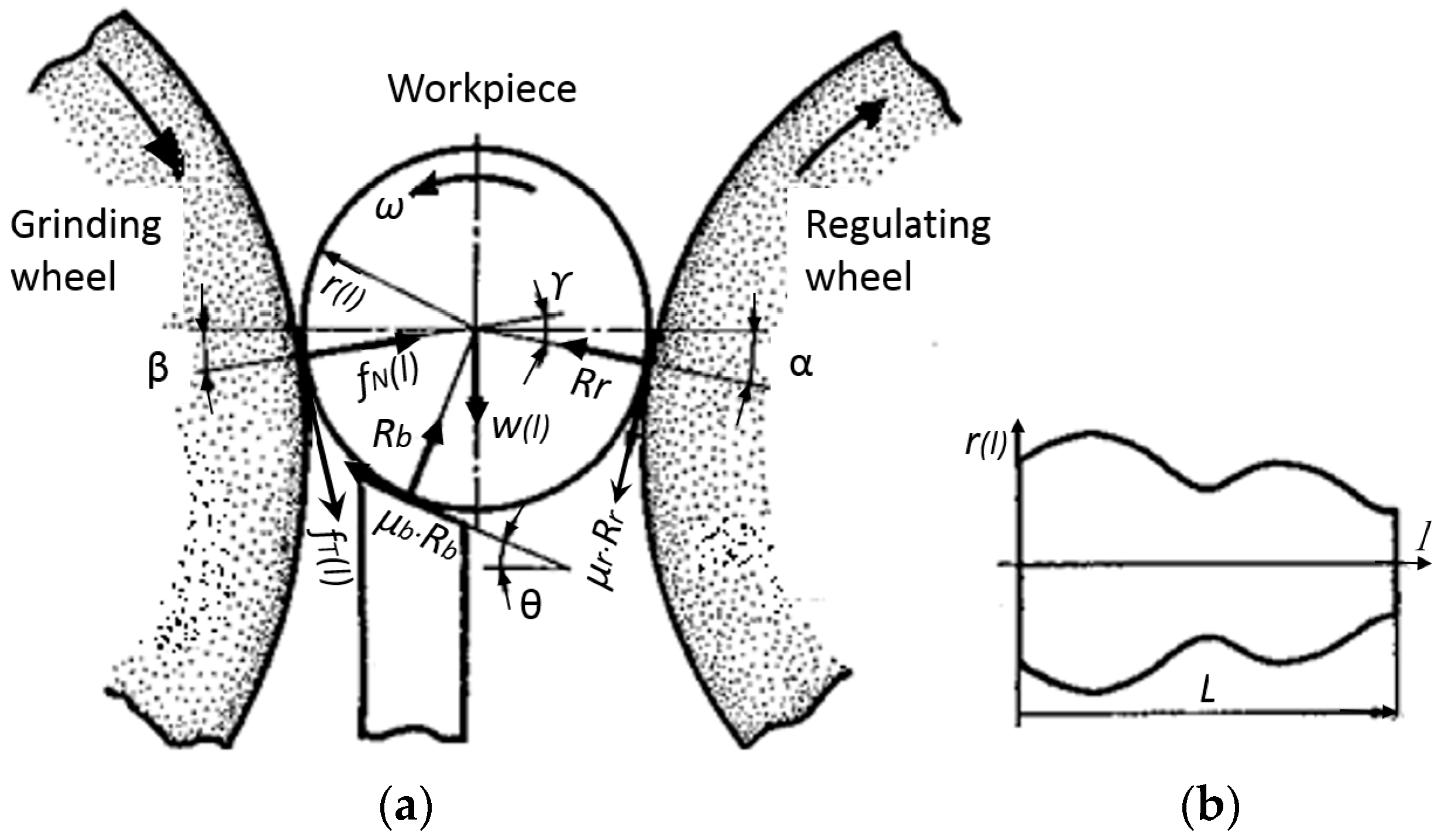
The basic setup parameters in centerless grinding are the blade angle θ, the center height angle γ and the work rotational speed nw, as shown in Figure 1.
The set (θ, γ, nw) of these parameters is called the “setup condition” in this paper, and it significantly affects centerless grinding performance. In practice, the work center height CH (instead of γ) and the RW (regulating wheel) rotation speed Nr (rpm) are used because these parameters can be directly set up on the machine. The center height CH (mm) has the following relationship with the center height angle γ (°) when angles α and β are small.
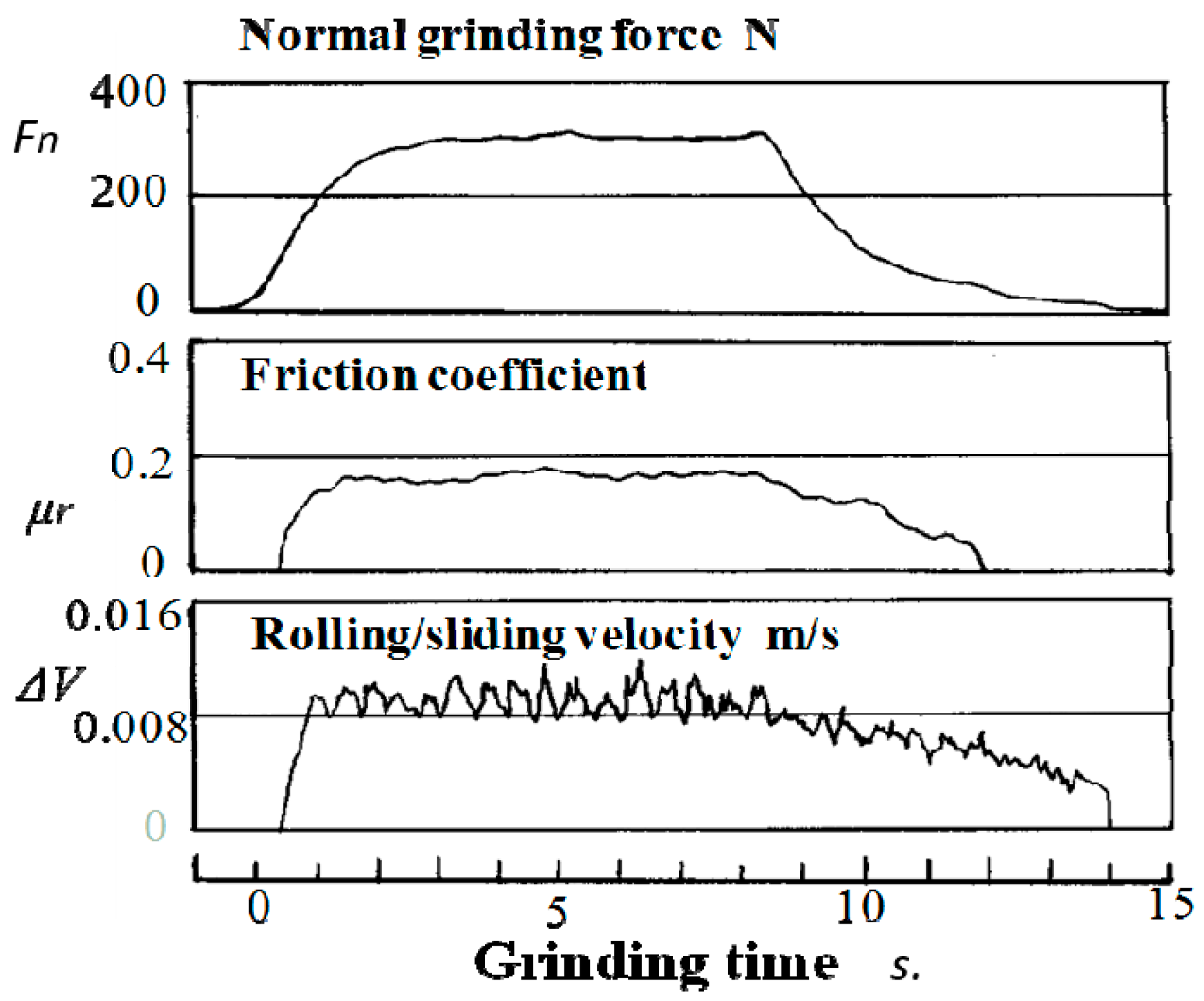
The work rotation speed nw is controlled by the RW friction drive/brake mechanism. Figure 2 shows test results of normal grinding force Fn, the friction coefficient μr and the rolling-sliding velocity between RW and the workpiece during an infeed centerless grinding process [15]. In steady state grinding, the sliding velocity ΔV, defined as (Vw − Vr), is about +0.008 m/s, and the slippage ratio ΔV/Vr is about 2%, where Vw and Vr are the work and RW peripheral velocities, respectively. Since the sliding velocity is very small, the work rotation speed nw can be represented by:
In the model development, the scientific parameters (θ, γ, nw) are used for the analysis of the optimum setup condition, and the practical parameters (θ, CH, Nr) are the outputs of the model.
3. Centerless Grinding Systems and the Characteristic Equation
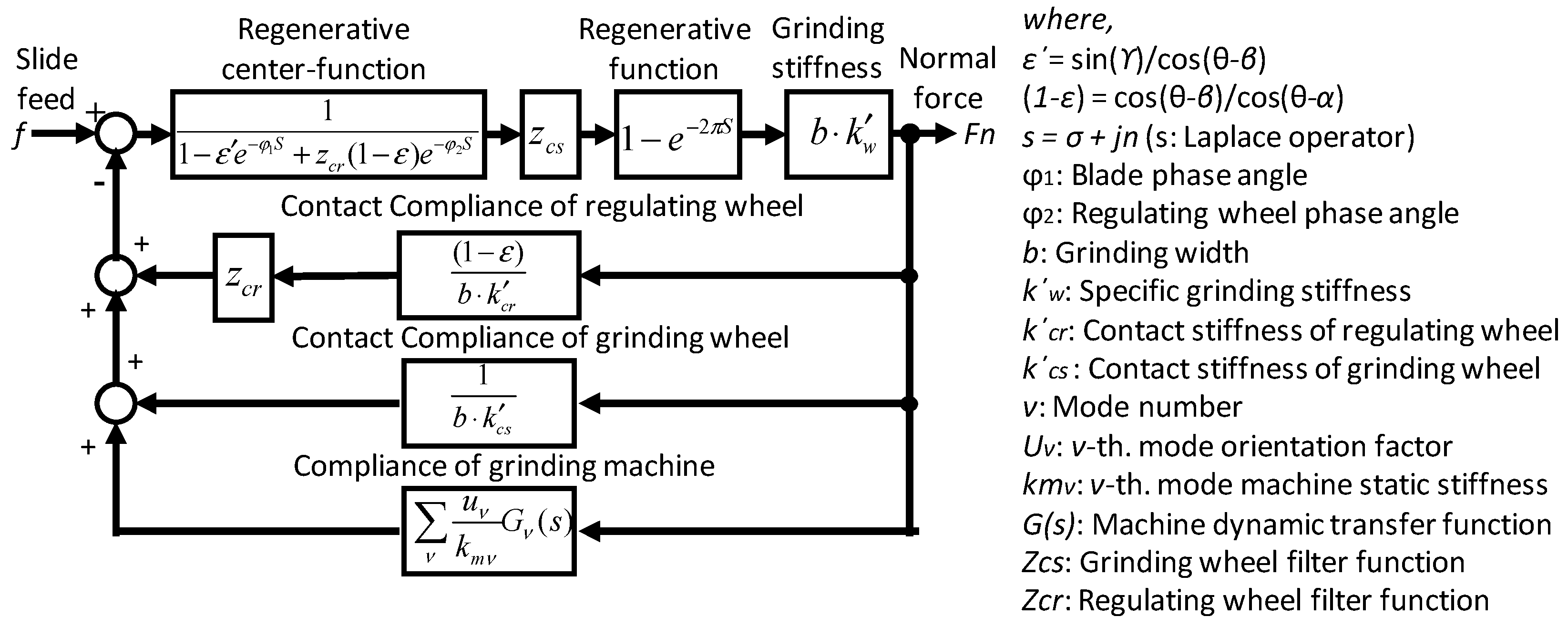
Since the three stability criteria influence each other and are significantly affected by the setup conditions, it is necessary to assess these stabilities as a total system—including the machine dynamic characteristics, the centerless grinding mechanism and the grinding processes. Figure 3 shows a block diagram of the centerless grinding system. The system consists of the regenerative centering mechanism [16], the regenerative function [17], the relationship between depth-of-cut and the normal grinding force, the contact stiffness of the wheels, the wheel filtering functions, and the machine dynamics [12]. The dynamic behavior of the rounding mechanism can be investigated based on the characteristic equation of the closed loop centerless grinding system in Figure 3.
The characteristic function is represented by:
where
By solving the characteristic roots of Equation (6), the dynamic rounding stability can be evaluated and the transient behavior of the waviness amplitude in work roundness can be calculated during the grinding process. The characteristic root can be represented by:
where s is the Laplace operator, σ is the amplitude growth rate per unit radian, and n is the number of lobes in the work roundness. The transient of the amplitude change A(t) on roundness waviness during the grinding process can be expressed by:
where A0 is the initial amplitude of the waviness, nw is the work rotation speed in rps and t is the grinding time. When σ is positive, the amplitude of n lobes grows with grinding time t and the grinding process can be identified as the chatter vibration. In case of σ < 0, the amplitude of n lobes is decreased with grinding time t, and the grinding process becomes stable with improved roundness.
When the effect of machine vibration is negligible, the response of the transfer function Gm(s) is degenerated to a constant and the resulting system is of a kinematic nature, referred to as “geometric rounding stability” [12]. Then, the characteristic equation is simplified as:
4. Three Stability Criteria in Centerless Grinding
4.1. Work Rotation Stability Criterion
Figure 4 shows the torques acing on the workpiece during the centerless grinding process. Tg is the grinding torque given by the tangential grinding force Ft. Tb and Tr are the friction torques acting on the blade and the regulating wheel, respectively. Under the stable grinding process, the following torque-quilibrium relationship is maintained. The work peripheral velocity Vw is controlled by the friction drive/brake mechanism of RW, and becomes almost the same as the RW peripheral velocity Vr.
However, once this quilibrium condition is broken by the excessive grinding torque Tg overcoming the friction torques (Tb + Tr) during grinding, the work velocity Vw suddenly increases toward the grinding wheel speed Vg.
This phenomenon, called “spinners”, can create a potentially very dangerous situation and should be avoided for safe operations.
Figure 5a,b show the geometrical arrangement of the centerless grinding process and the forces acting on the workpiece at any cut section perpendicular to the work axis l during grinding. The variables fT and fN represent the tangential and normal grinding forces per unit width at the cut section. Rb and Rr are the resultant forces, while μb and μr are the friction coefficients at the contact points with the blade and the RW, respectively. w(l) is the work weight per unit width at the cut Section 1. The torque equilibrium equation can be written by:
where
I and ω are the mass moment of inertia and the angular velocity of the workpiece. k is the force ratio (fN/fT). For convenience, the plus sign of μr is assigned to the downward friction force and the minus sign is assigned to the upward one.
The generalized motion Equation (14) is applicable to any cylindrical-shaped workpiece; for example, simple cylindrical, tapered, and multiple stepped diameter workpieces. Equation (14) indicates that, in addition to being affected by the primary setup conditions (θ, γ), the rotational motion of the workpiece is affected by the grinding forces and the friction force on RW.
The upper-limit tangential grinding force fU under the stable grinding condition is derived from Equation (14).
where μr0 is the maximum static friction coefficient of RW. When the tangential grinding force fT is smaller than fU, the work rotation speed Vw can be controlled with the RW speed Vr.
Figure 6 shows the results of the calculation of fU with respect to the blade angle θ with various friction coefficients μr0. The grinding force fU is normalized with the diameter d of a simple cylindrical workpiece made of steel. fU increases with increased θ. When θ is greater than a certain angle with μr0, the fU value becomes infinite. Under this condition, there is no risk of the spinners phenomenon occurring. The zone with the infinite fU value is called the “safe operation zone.” For instance, there is no limit on fU when a blade of θ > 42° is used with an RW of μr0 = 0.25.
Figure 7 shows the safe operation zones under various μr0 values on the (θ–γ) chart and provides guidelines for satisfying the work rotation stability criterion (WRSC). Stable grinding without any risk of spinners can be obtained by selecting the set of (θ, γ) from the safe operation zone, and the WRSC is satisfied with the setup conditions (θ, γ).
4.2. Geometrical Rounding Stability Criterion
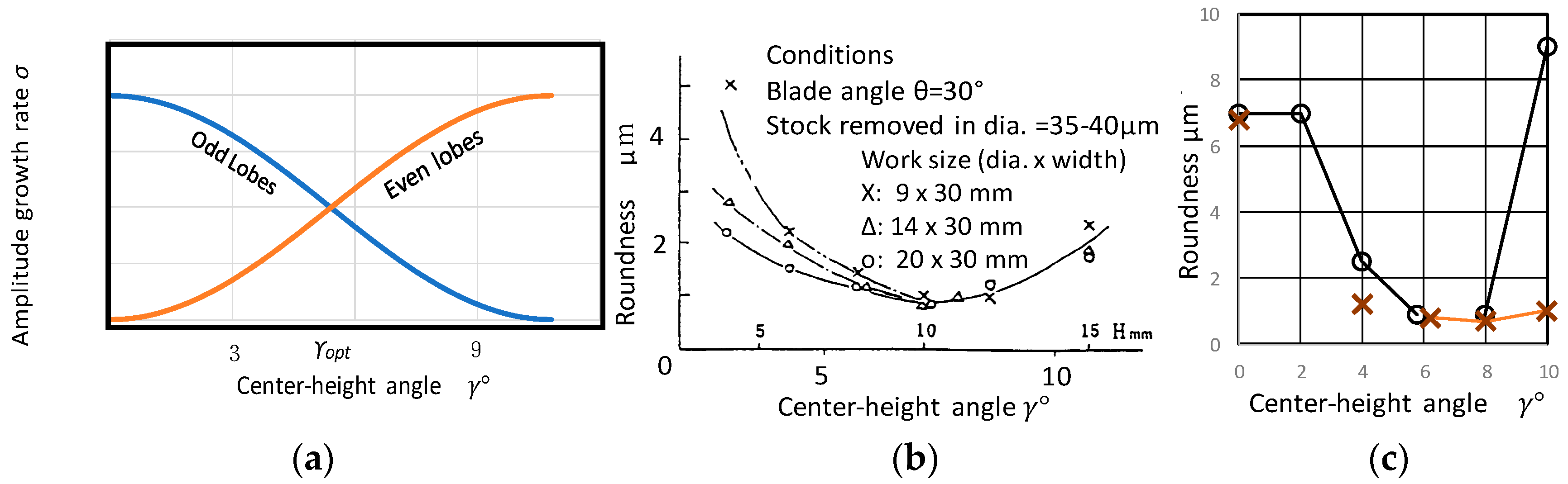
When the grinding system is stable and the influence of the machine dynamics on the rounding mechanism is negligible, the stability of the rounding mechanism is predominantly affected by the geometrical arrangement of the centerless grinding system under the solid-body machine structure. By analyzing the characteristic roots of Equation (11), the effect of the center height angle γ on geometrical rounding stability can be assessed. Figure 8a shows the characteristic root distributions for the odd lobes and the even lobes [14]. When a lower center height angle such as γ < 3° is set up, the amplitude growth rates of the 3, 5, and 7 lobes become close to zero, and the roundness error due to these odd lobes cannot be improved during the grinding process. On the other hand, when a higher center height angle such as γ > 9° is set up, the amplitude growth rates of even lobes like 18, 20, and 22 become close to zero and the roundness error cannot be improved due to the even-lobe waviness.
These results suggest the existence of an optimum center height angle γopt that yields a minimum roundness error, and γopt = 6.7° has been proposed as that optimum angle [12]. Miyashita et al. reported the experimental results shown in Figure 8b, and indicated that the optimum center height angle exists around 7° [6]. Rowe et al. reported on theoretical and experimental analysis of the rounding mechanism of a workpiece with a flat face. Figure 8c shows the effect of the center height angle on the roundness error. The grinding test results verified that the optimum center height angle γopt exists around 6°–8° [8].
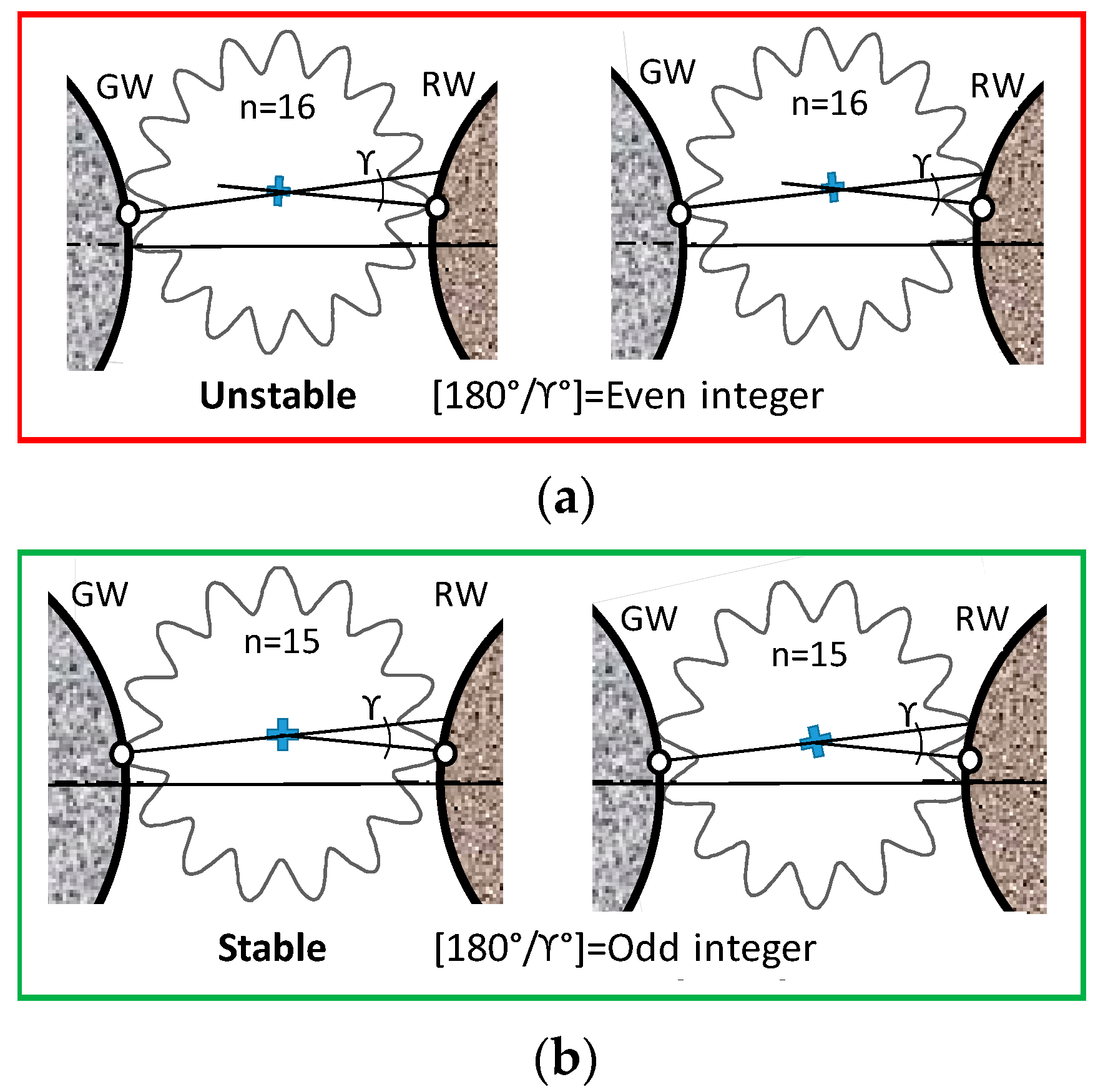
It is well known that an odd number of lobes appears under a lower center height condition such as γ < 3°, as shown in Figure 9a. To minimize the roundness error with odd numbers of lobes, it is recommended that lower center height angles be avoided as much as possible. Under a relatively higher center height condition, a specific even number of lobes appears, as shown in Figure 9b. Where the center height angle is known, the even number of lobes ne that will appear can be found by 180/γ [6].
These even numbers of lobes are the result of the geometrical rounding instability caused by the geometrical arrangement of the regulating wheel or the blade. Figure 10 and Figure 11 show the geometrical rounding stability criteria of the regulating wheel and the blade, respectively.
Figure 10a is an example of regulating wheel geometrical rounding instability. When a peak of waviness on the work roundness contacts with the regulating wheel and the waviness becomes a valley at the grinding point (and vice versa), the waviness error cannot be removed during the grinding process. Conversely, Figure 10b is an example of regulating wheel geometrical stability. When a peak contacts with the regulating wheel and the waviness becomes a peak at the grinding point (and vice versa), the waviness error can be removed during the process. Therefore, the regulating wheel geometrical rounding stability criterion (RW − GRSC) can be summarized as follows:
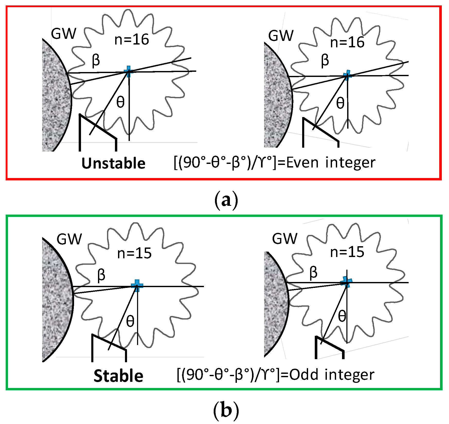
Likewise, Figure 11a is an example of blade geometrical rounding instability. When a peak of waviness contacts with the top surface of the blade and the waviness becomes a peak at the grinding point (and vice versa), the waviness error cannot be removed. In addition, again, Figure 11b is an example of blade geometrical rounding stability. When a valley contacts with the top surface of the blade and the waviness becomes a peak at the grinding point (and vice versa), the waviness error can be removed. Similarly, the blade geometrical rounding stability criterion (B − GRSC) can be summarized as follows:
To satisfy the RW geometrical rounding stability criterion (RW − GRSC), the center height angle γ is determined by:
where Iodd is an odd integer. Also, the blade geometrical stability criterion (B − GRSC) can be satisfied by setting up the center height angle γ that can be calculated by the following equation.
4.3. Dynamic System Stability Criterion
As mentioned, the chatter vibration in the centerless grinding system is very severe and builds up fast because the work-regenerative self-excited vibration has such a high amplitude growth rate, as shown in Figure 12a. This phenomenon not only deteriorates grinding accuracy and productivity, but also threatens safe operations. To achieve a stable grinding process with high grinding accuracy as shown in Figure 12b, satisfying the dynamic system stability criterion is imperative.
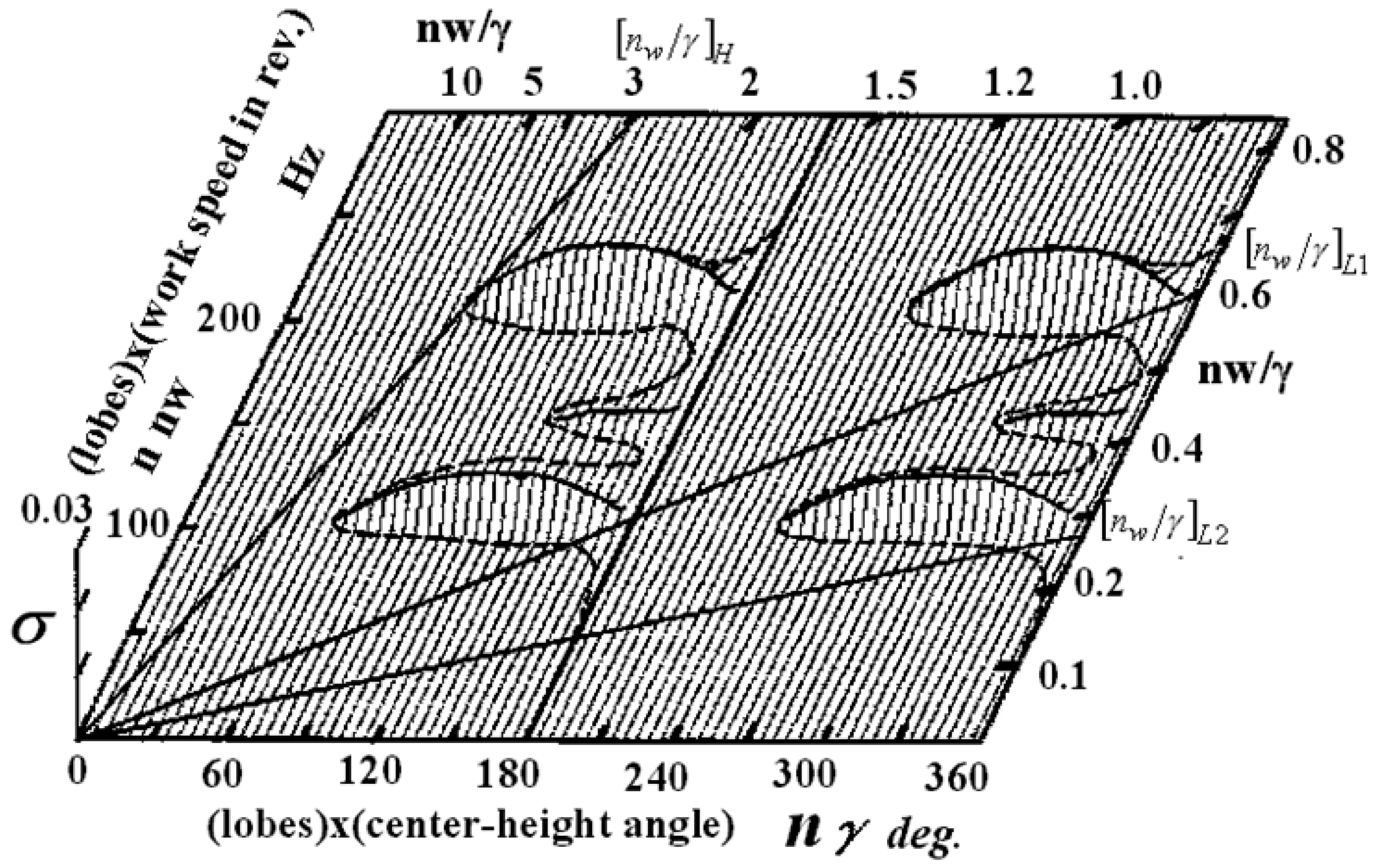
Study of the characteristic root distributions of Equation (6) clarifies the generation mechanism of the chatter vibration [12], and the chatter generation zones are revealed on the (n·γ–n·nw) diagram for the dynamic system stability criterion (DSSC). Figure 13 plots the 3D positive growth rates σ of the characteristic roots on the (n·γ–n·nw) diagram. The chatter zones are shown as “mountains” located near the natural frequencies in the (n·nw) axis. The higher the height of the mountain, the more severe the chatter vibration. Since the chatter mountains are in 0 < (n·γ) < 180°, they generate even numbers of lobes during chatter vibration.
The chatter zones located in 180° < (n·γ) < 360° generate odd numbers of lobes and generate chatter vibration only under higher γ values. A straight line (nw/γ) through the origin is determined when the center height angle γ and the work speed nw are given. Where the straight line hits a mountain, chatter vibration occurs at that frequency. In other words, where the straight line given by the ratio (nw/γ) does not hit any mountains, the DSSC is satisfied and chatter-free grinding is achieved. Figure 13 shows distinct areas that satisfy the DSSC and gives the ranges of (nw/γ) that provide chatter-free grinding.
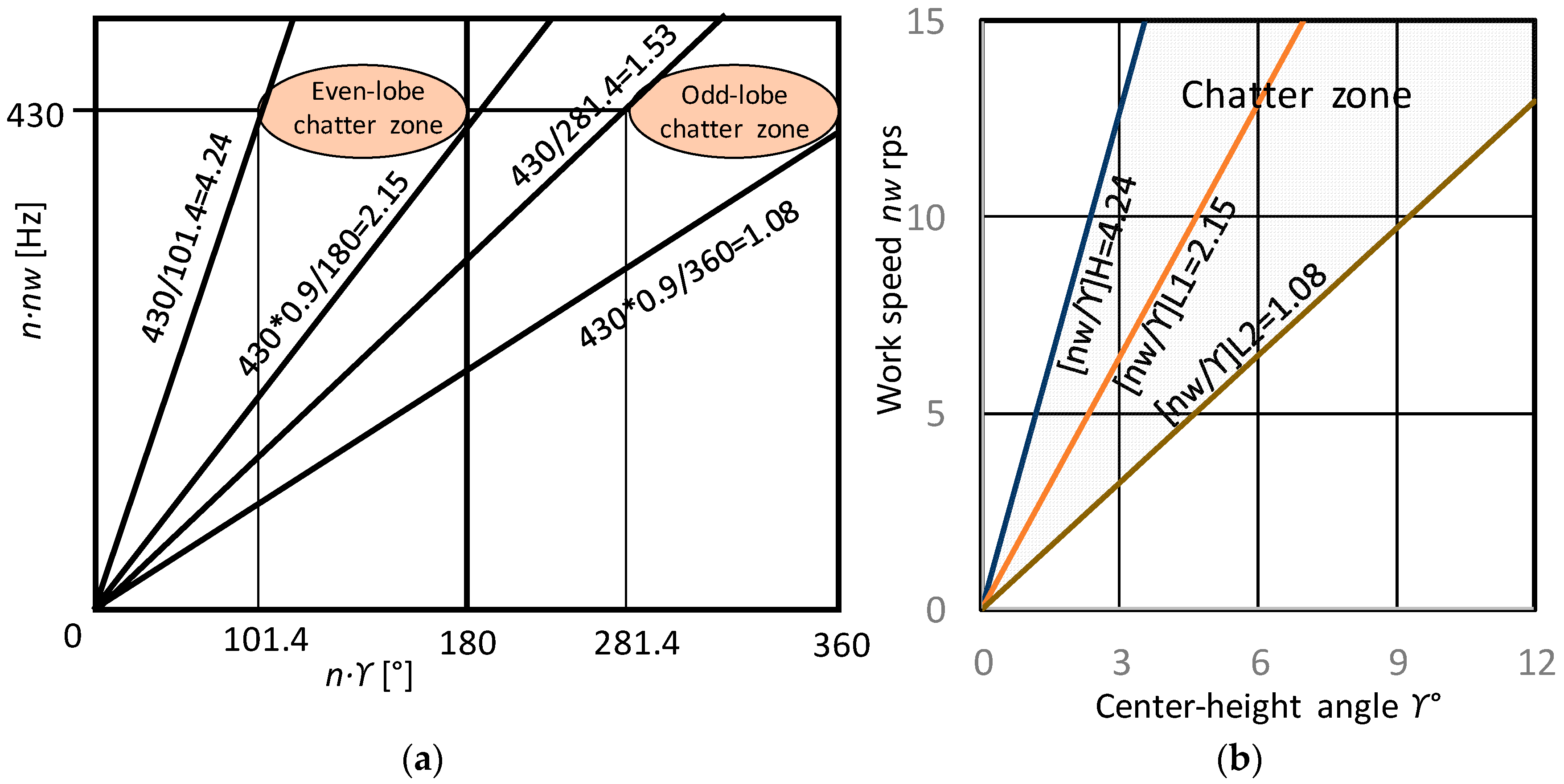
Each grinding machine has its own dynamic characteristics with different natural frequencies, and a (n·γ–n·nw) diagram can be plotted that shows its unique chatter zones. The chatter zones are identified by conducting systematic grinding tests. Figure 14a shows the chatter zones of grinding machine A. The chatter zones located near the natural frequencies of 100 Hz, 150 Hz and 200 Hz are shown on the vertical axis (n·nw) Hz. These chatter zones are located in 0 < (n·γ) < 180° and generate even numbers of lobes, while the zones located in 180° < (n·γ) < 360° generate odd numbers of lobes where γ > 6.7°. Figure 14b shows the chatter zones for grinding machine B. Machine B is designed with high, rigid structures and possesses spindles with very high stiffness. The first chatter zone appears at the natural frequency of 430 Hz, which is very high, and machine B creates wider chatter-free regions than conventional machine A.
Figure 15a shows the chatter zones of grinding machine A plotted on a (γ–nw) chart. The practical (γ–nw) chart can describe chatter zones, but cannot describe the chatter generation mechanism, the chatter zones’ various vibration modes, or the areas where stable grinding can occur. However, the (γ–nw) chart is very effective in setup operations when used along with the analytical (n·γ–n·nw) diagram. The ranges of chatter zones in (nw/γ) are explicitly given, as shown in Figure 15b.
Three types of stable, no-chatter zones exist for high work speed and low work speed regions. The chatter-free conditions for machine A are:
- 1.
- (nw/γ) H > 3.0 (high-speed chatter-free zone; KH)
- 2.
- (nw/γ) L1 < 0.6 when γ is lower (low-speed chatter-free zone 1; KL1)
- 3.
- (nw/γ) L2 < 0.28 when γ is higher (low-speed chatter-free zone 2; KL2)
- 4.
- (nw/γ) H > 4.24 (KH)
- 5.
- (nw/γ) L1 < 2.15 (KL1) for γ < 6.67°
- 6.
- (nw/γ) L2 <1.08 (KL2) for γ > 6.67°
Figure 16a shows a narrow stable zone in 1.53 < (nw/γ) < 2.15. The setup for this chatter-stable zone is too risky to use, so it is not considered an area of stable, chatter-free conditions.
Since the work speed nw is controlled by the regulating wheel speed Nr, it is helpful to convert the (γ–nw) charts (Figure 15b and Figure 16b) into a (γ–Nr) chart, as shown in Figure 17. For practical setup operations, the range of the center height angle is set to γ = 3° to 9°. Also, in this case the range of the speed ratio q (defined as the ratio of the work speed Vw to the grinding speed Vg) for surface roughness control is set to 1/q = 25 to 150. In Figure 17, three chatter-free stable zones—KH, KL1 and KL2—are shown within the constrained range. The dynamic system stability criterion is satisfied when a set of (γ, Nr) is selected from the chatter-free stable zones KH, KL1 and KL2.
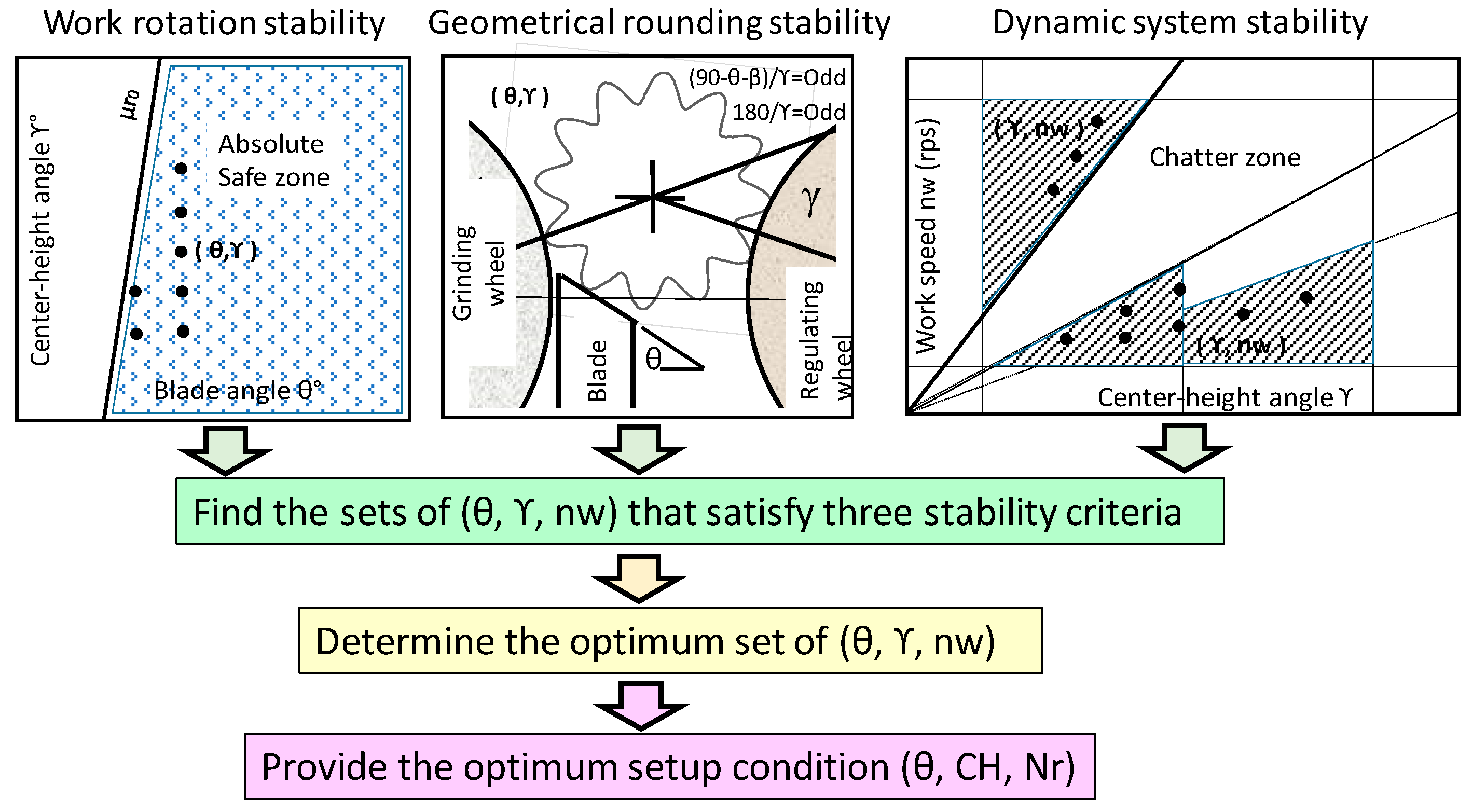
5. Modeling to Find the Optimum Setup Conditions that Satisfy the Three Stability Criteria of Centerless Grinding
The previous section discussed the determination of setup conditions that would satisfy each individual stability criterion. This section discusses the development of a model for the optimum setup conditions that will simultaneously satisfy all three stability criteria.
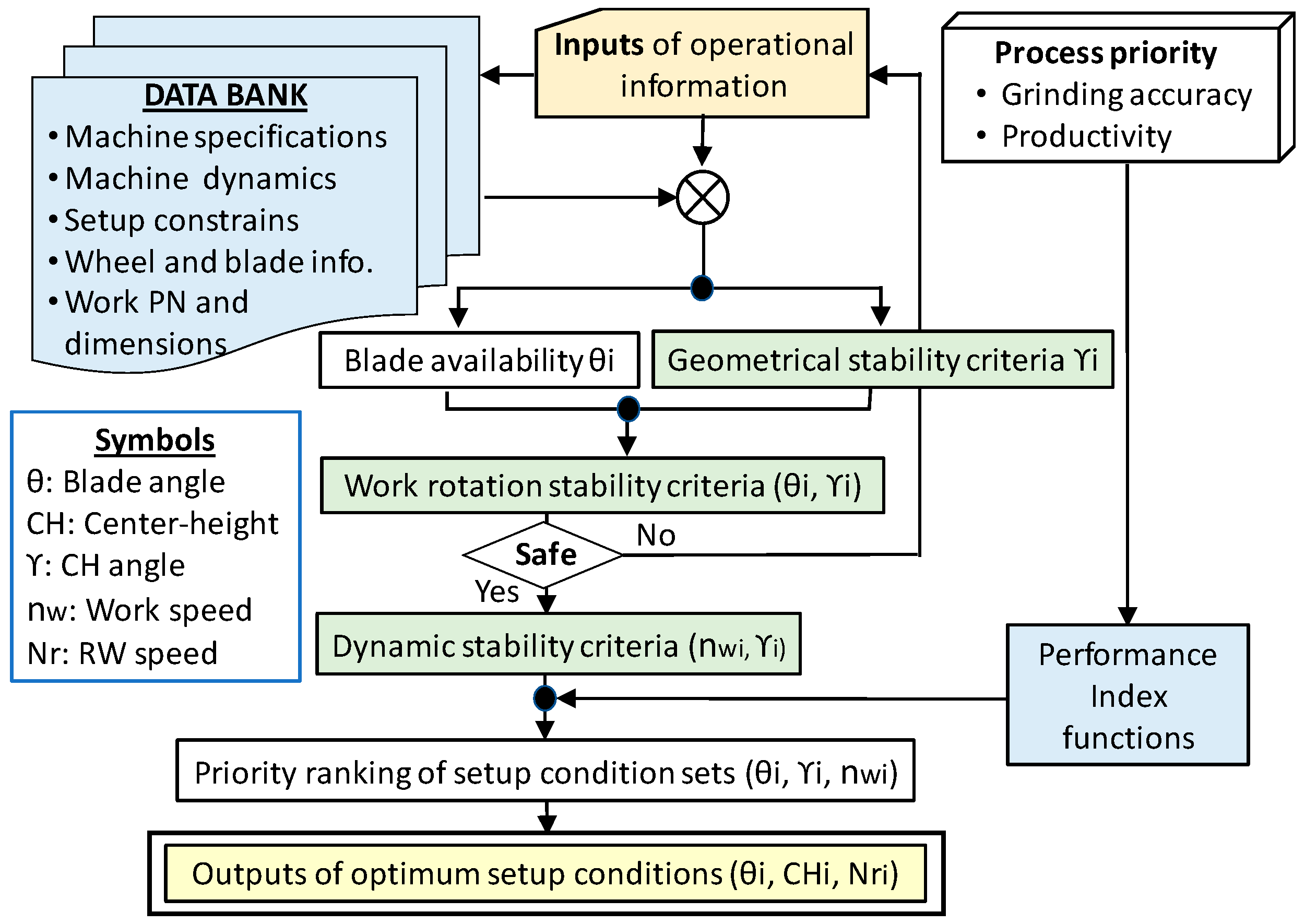
Figure 18 describes the structure of the developed model. As the first step, the sets of (θ, γ) (blade angle θ, center-height angle γ) satisfying the three individual stability criteria are determined. To satisfy the work rotation stability criterion, the sets of (θ, γ) are selected from the safe operation zone shown in Figure 7, analyzed with the varying maximum friction coefficient μr0 of a given regulating wheel. Also, the sets of (θ, γ) satisfying both geometrical rounding stability criteria—RW − GRSC and B − GRSC—are calculated. Then, the sets of (nw, γ) (work speed nw and γ) that satisfy the dynamic system stability criterion are found. The sets of (nw, γ) are selected from one of the stable chatter-free zones: KH, KL1 or KL2 (see Figure 17).
The second step is to find the sets of (θ, γ, nw) satisfying all three stability criteria. The third step is to determine the optimum set from among the population of the (θ, γ, nw) sets by calculating the PI (performance index) function based on the process aim (accuracy or productivity). Finally, the optimum set (θ, γ, nw) is converted into practical setup conditions (blade angle θ, center height CH, RW speed Nr) as the outputs of the developed model.
Figure 19 is the flow chart of “Opt-Setup Master”, the developed model. The model requires a machine operator to provide some input information, as shown in Table 1. All parameters required for the calculation of the Opt-Setup Master are referenced from the data bank, which stores machine specifications, machine dynamic characteristics, work part numbers with dimensions, RW friction characteristics, blade availability, etc. The constraints of the setup parameters are also stored in the data bank, as shown in Table 2.
The Opt Setup Master calculates the boundary line of the safe operation zone on the safe operation chart by using the following relationship between the dressing lead leadr and the maximum friction coefficient μr0 of the rubber bonded regulating wheel [15].
where a is a constant. a = 0.14 and a = 0.02 for a SPD (single-point dresser) and an RD (rotary dresser), respectively.
The boundary line of the safe operation zone on the (θ, γ) chart can be expressed by:
where
When θ1 of a point (θ1, γ1) is greater than (γ1–b)/m, the point is located at the right side of the safe operation zone boundary line and meets the work rotation stability criterion.
The first calculation of the Opt-Setup Master is to find the sets of (θg, γg) that meet the geometrical rounding stability criteria RW − GRSC and B − GRSC. The next calculation is to determine if the sets (θg, γg) are located within the safe operation zone under the given dressing conditions of the rubber bonded regulating wheel. If they are (answer “yes”), the sets (θgw, γgw) satisfy both the geometrical rounding and the work rotation stability criteria. The final calculation is to find the work speed nw by using γgw and the chatter stability boundary lines of (nw/γgw). From these calculations, the optimum sets of (θ, γ, nw) are discovered.
Then, the performance index (PI) functions that were prepared based on the process aims are applied to assess the optimum sets of (θ, γ, nw). The PI functions are summarized in Table 3. The weighting factors of the PI functions are determined by applying theoretical knowledge, experimental knowledge and operational skills. PI functions can be updated with newly gained knowledge and skills. For each process aim (accuracy or productivity), the values of the PI function for all setup conditions are calculated and these sets are ranked in ascending order from minimum to those with greater values. The smaller the PI values, the more suitable the setup conditions. The setup conditions with the smallest PI function values are defined as the optimum setup conditions.
Table 4 shows examples of the Opt-Setup Master outputs. The conditions of the model simulation are:
- (1)
- machine B is applied
- (2)
- the process aim is accuracy-oriented
- (3)
- the work shape and the size are a cylindrical workpiece with 40 mm (D) × 60 mm (L)
- (4)
- the rubber bonded RW is dressed with leadr = 0.5 mm/rev by SPD
- (5)
- the GW diameter is 453 mm
- (6)
- the RW diameter is 350 mm
- (7)
- the available blade angles are θ = 27.5° and θ = 40.3°
Ranking No. 1 has the optimum setup conditions, as it has the smallest PI values. The practical setup parameters are a blade angle θ = 40.3° with a thickness of 20 mm, a center height of CH = 12.68 mm and RW speed of Nr = 41.8 rpm. The center height angle is γ = 6.68°, the work speed is nw = 6.1 rps and the 1/q is 25.
The optimum setup condition set was selected from the safe operating zone. Therefore, it meets the work rotation stability criterion and ensures safe operations. Further, the optimum setup condition set was selected from the stable zone KL2 for chatter-free grinding, and thus meets the dynamic system stability criterion. Also, the optimum setup condition set meets the criteria of both Equations (23) and (25) (180/6.68 = 27 and (90 − 40.3 − 2.95)/6.68 = 7), so the geometrical rounding stability criteria are maintained.
Through these means, it is verified that the optimum setup condition set—provided as the outputs from the Opt-Setup Master—simultaneously satisfies all three stability criteria for centerless grinding.
Table 5 shows the optimum setup conditions as calculated by the Opt-Setup Master for infeed centerless grinding of cylindrical workpieces of various sizes by two different grinding machines, A and B. In all cases, γ = 6.67°, one of the most preferable γ angles, is chosen. All values representing RW − GRSC and B − GRSC are odd integers, indicating that all the setup conditions meet the geometrical rounding stability criteria. Machine B has a greater chatter DSSC index (nw/γ) than machine A in chatter-stable zones KH, KL1 and KL2. Machine B’s high stiffness creates more extensive chatter-stable zones than conventional machine A.
6. Conclusions
Centerless grinding systems possess some unique features, including their work rotation drive, loose work holding and regenerative centering mechanisms. However, because of these features, three fundamental stability issues arise. Many researchers have investigated the issues and provided useful guidelines for solving the issues.
This paper summarizes the three fundamental stability issues: (1) work rotation stability for safe operation with no spinners; (2) geometrical rounding stability for better roundness; and (3) dynamic system stability for chatter-free grinding. It emphasizes the need for an analytical tool that can provide optimal setup conditions—those conditions that will satisfy all three stability criteria simultaneously. This paper describes a newly developed analytical tool named Opt-Setup Master, and discusses how the three stability criteria can be met.
The developed Opt-Setup Master has the following features:
- (1)
- Accepts various shapes of workpiece: cylindrical, tapered, spherical and multi-stepped
- (2)
- Applicable to any centerless grinding machine
- (3)
- Data management via a data bank
- (4)
- Inputs are easy to enter and outputs are readily usable
- (5)
- Designed for operators
- (6)
- Provides scientific parameters for engineers/managers
- (7)
- Finds all setup conditions satisfying the three stability criteria of centerless grinding systems
- (8)
- Outputs the optimum condition based on process aim
Conflicts of Interest
The authors declare no conflict of interest.
References
- Hashimoto, F.; Gallego, I.; Oliveira, J.F.G.; Barrenetxea, D.; Takahashi, M.; Sakakibara, K.; Stålfelt, H.-O.; Staadt, G.; Ogawa, K. Advances in Centerless Grinding Technology. CIRP Ann. Manuf. Technol. 2012, 61, 747–770. [Google Scholar] [CrossRef]
- Hashimoto, F.; Suzuki, N.; Kanai, A.; Miyashita, M. Critical Range of Set-up Conditions of Centerless Grinding and Problem of Safe Machining Operation. Jpn. Soc. Precis. Eng. 1982, 48, 996–1001. [Google Scholar] [CrossRef]
- Hashimoto, F.; Lahoti, G.; Miyashita, M. Safe Operations and Friction Characteristics of Regulating Wheel in Centerless Grinding. Ann. CIRP 1998, 47, 281–286. [Google Scholar] [CrossRef]
- Abrasive Industry. Anon, Centerless Grinding Operation; Abrasive Industry: Auckland, New Zealand, 1925; pp. 102–105. [Google Scholar]
- Dall, A.H. Rounding Effect in Centerless Grinding. Mech. Eng. 1946, 68, 325–332. [Google Scholar]
- Ogawa, M.; Miyashita, M. On Centerless Grinding (1)—Theoretical Treatise on Rounding Action. Jpn. Soc. Precis. Eng. 1957, 24, 89–94. [Google Scholar] [CrossRef]
- Reeka, D. On the Relationship between the Geometry of the Grinding Gap and the Roundness Error in Centerless Grinding. Ph.D. Thesis, RWTH, Aachen University, Aachen, Germany, 1967. [Google Scholar]
- Rowe, W.B.; Barash, M.M.; Koenigsberger, F. Some Roundness Characteristics of Centerless Grinding. Int. J. Mach. Tool Des. Res. 1965, 5, 203–215. [Google Scholar] [CrossRef]
- Yonetsu, S. Study on Centerless Grinding—First Report. Jpn. Soc. Mech. Eng. 1953, 19, 53–59. [Google Scholar]
- Gurney, J.P. An Analysis of Centerless Grinding. Trans. ASME J. Eng. Ind. 1964, 86, 163–174. [Google Scholar] [CrossRef]
- Furukawa, Y.; Miyashita, M.; Shiozaki, S. Vibration Analysis and Work Rounding Mechanism in Centerless Grinding. Int. J. Mach. Tool Des. Res. 1970, 44, 145–175. [Google Scholar] [CrossRef]
- Hashimoto, F.; Zhou, S.S.; Lahoti, G.D.; Miyashita, M. Stability Diagram for Chatter Free Centerless Grinding and Its Application in Machine Development. Ann. CIRP 2000, 49, 225–230. [Google Scholar] [CrossRef]
- Gallego, I. Intelligent Centerless Grinding: Global Solution for Process Instabilities and Optimal Cycle Design. Ann. CIRP 2007, 56, 347–352. [Google Scholar] [CrossRef]
- Hashimoto, F.; Lahoti, G.D. Optimization of Set-up Conditions for Stability of the Centerless Grinding Process. Ann. CIRP 2004, 53, 271–274. [Google Scholar] [CrossRef]
- Hashimoto, F. Effects of Friction and Wear Characteristics of Regulating Wheel on Centerless Grinding. In Proceedings of the SME, Third International Machining and Grinding Conference, Cincinnati, OH, USA, 4–7 October 1999; pp. 1–18. [Google Scholar]
- Rowe, W.B.; Koenigsberger, F. The Work-Regenerative Effect in Centerless Grinding. Int. J. Mach. Tool Des. Res. 1964, 4, 175–187. [Google Scholar] [CrossRef]
- Snoeys, R.; Brown, D. Dominating Parameters in Grinding Wheel and Workpiece Regenerative Chatter. In Proceedings of the 10th International Machine Tool Design and Research Conference, LanPleacaster, UK, 10–14 September 1969; Pergamon Press: Oxford, UK, 1970; pp. 325–348. [Google Scholar]
Figure 1.
Setup conditions in centerless grinding.
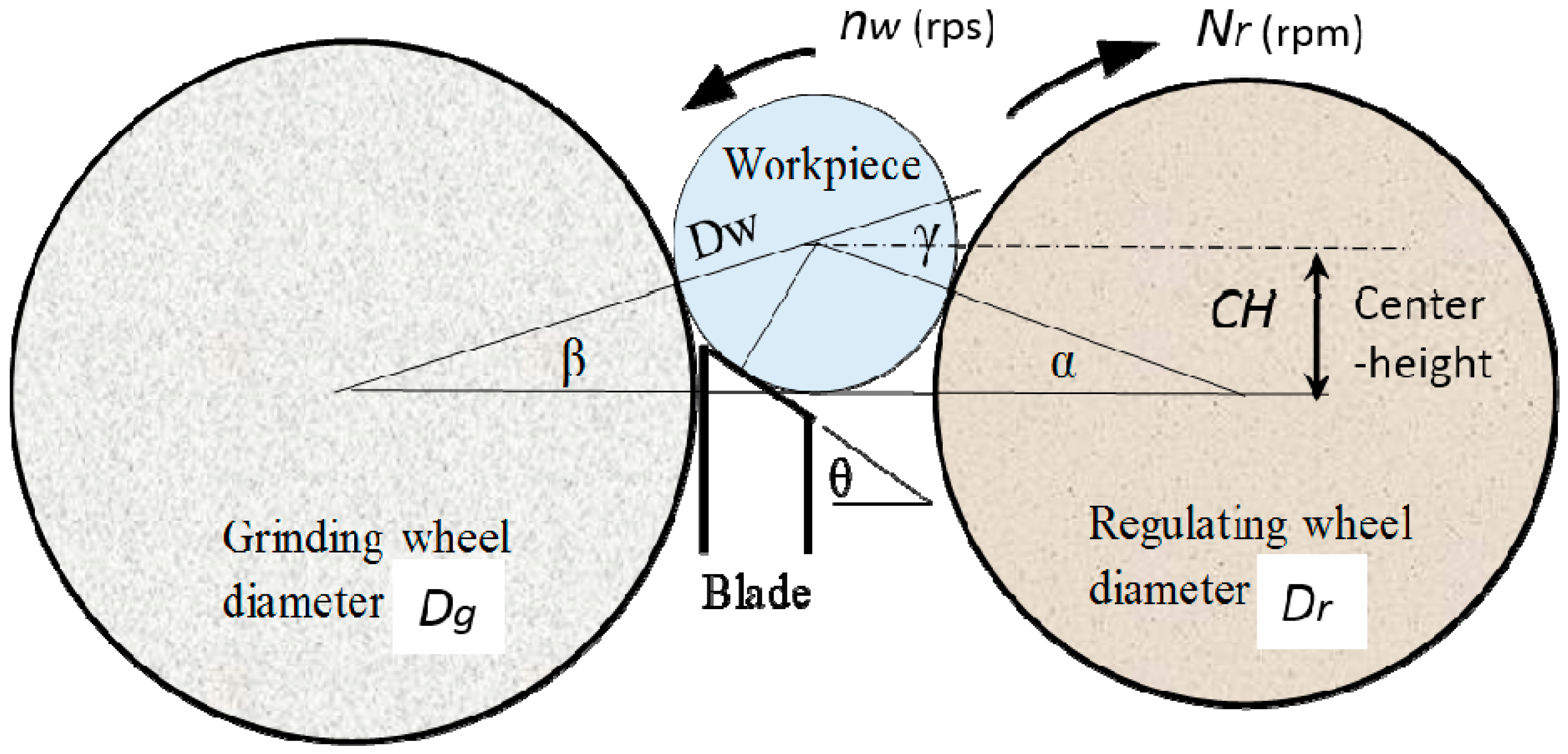
Figure 2.
Infeed centerless grinding process. Dr = 255 mm, Dw = 30 mm, Nr = 30 rpm, Vw = 0.4 m/s, Sliding velocity: 0.008 m/s, Slippage ratio: 2%.
Figure 2.
Infeed centerless grinding process. Dr = 255 mm, Dw = 30 mm, Nr = 30 rpm, Vw = 0.4 m/s, Sliding velocity: 0.008 m/s, Slippage ratio: 2%.

Figure 3.
Block diagram of centerless grinding system.

Figure 4.
Torques acting on workpiece during centerless grinding.
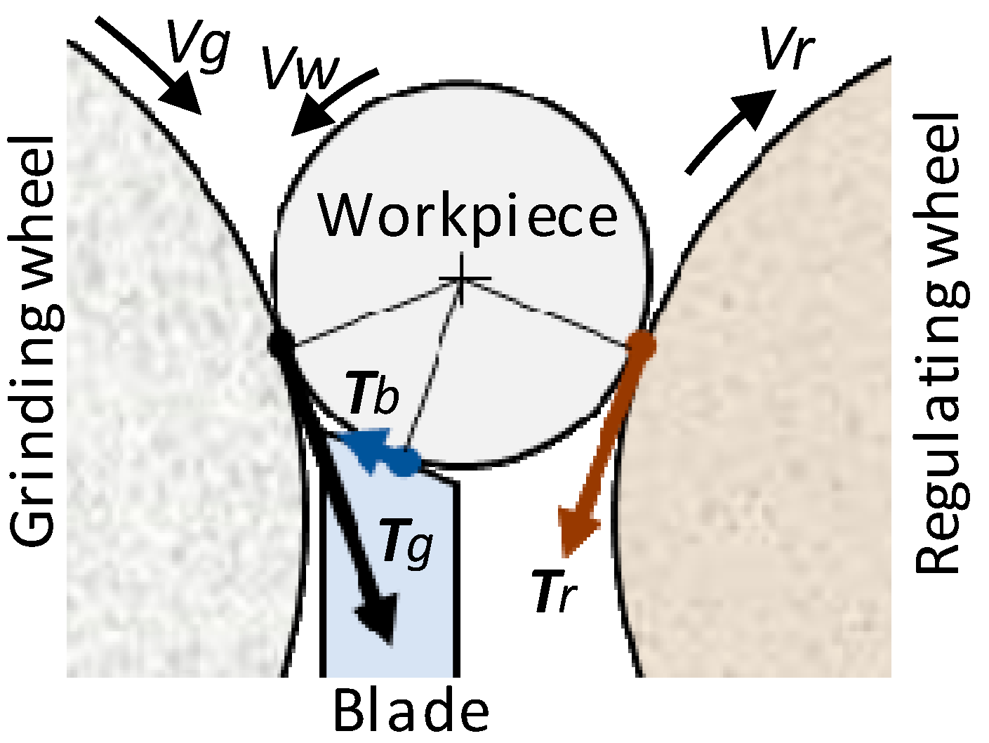
Figure 5.
Arrangement of centerless grinding and forces acting on workpiece. (a) Forces acting on workpiece during centerless grinding; (b) Cylindrical workpiece.
Figure 5.
Arrangement of centerless grinding and forces acting on workpiece. (a) Forces acting on workpiece during centerless grinding; (b) Cylindrical workpiece.

Figure 6.
Upper limit tangential grinding force.

Figure 7.
Safe operation chart.
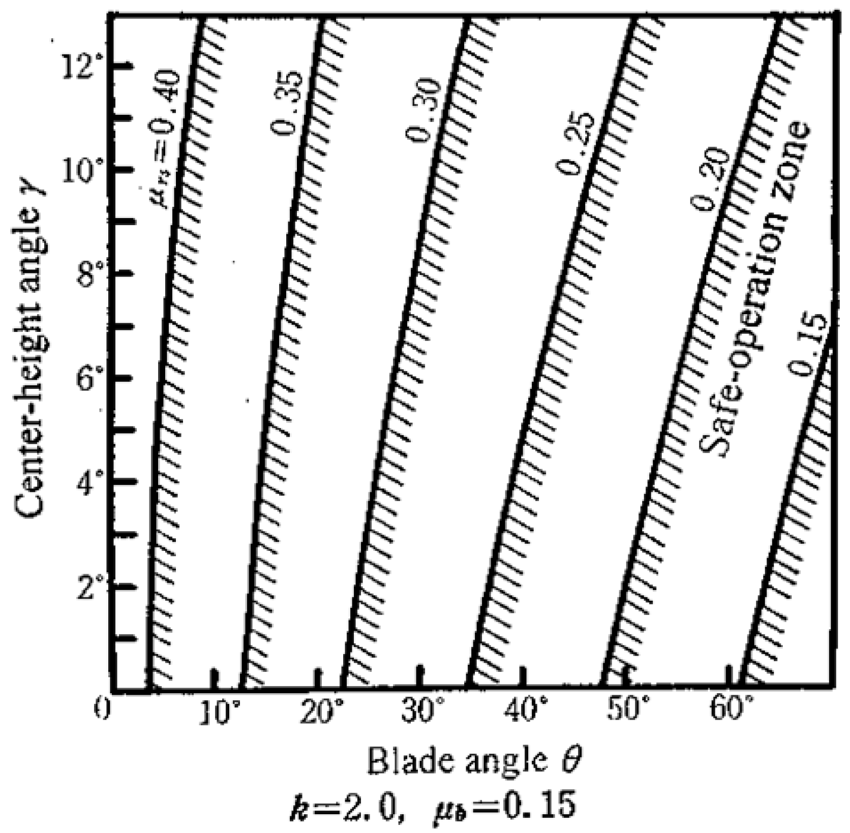
Figure 8.
Geometrical rounding stability. (a) Center-height angle vs. amplitude growth rates [14]; (b) Effect of γ on roundness [6]; (c) Effect of γ on roundness [16].

Figure 9.
Effect of center-height angle on rounding mechanism. (a) Odd lobe appearance at lower γ; (b) Even lobe appearance at a specific γ.
Figure 9.
Effect of center-height angle on rounding mechanism. (a) Odd lobe appearance at lower γ; (b) Even lobe appearance at a specific γ.
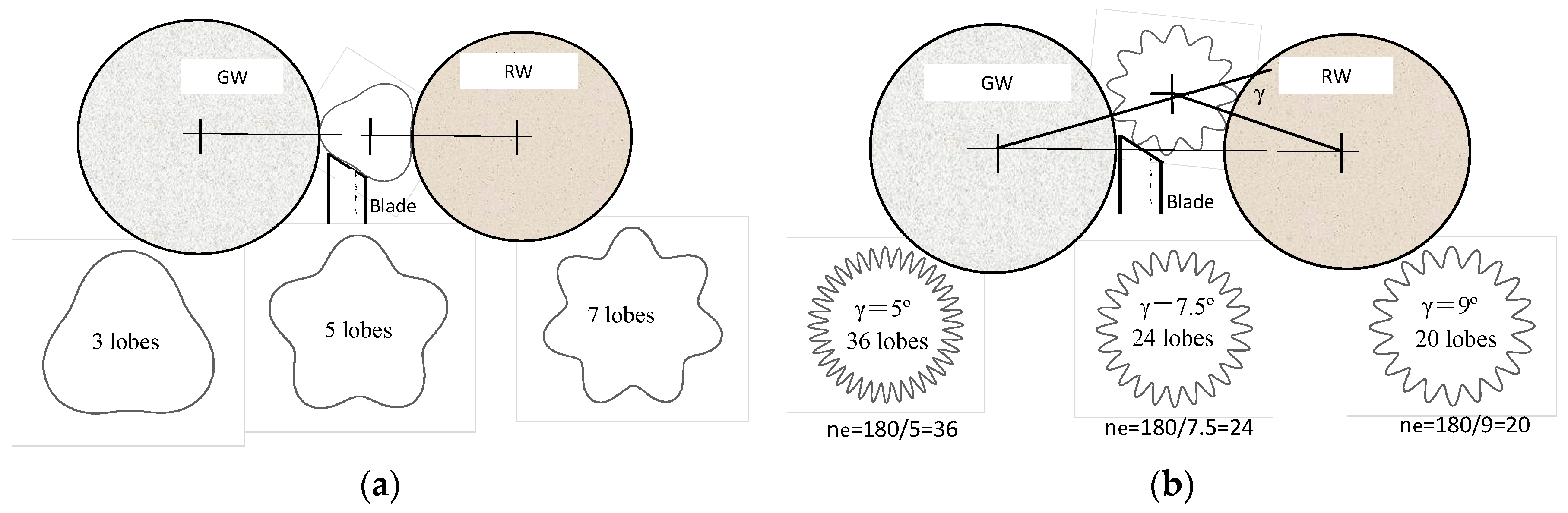
Figure 10.
Regulating wheel (RW) geometrical rounding stability criteria. (a) RW geometrical rounding unstable conditions; (b) RW geometrical rounding stable conditions.
Figure 10.
Regulating wheel (RW) geometrical rounding stability criteria. (a) RW geometrical rounding unstable conditions; (b) RW geometrical rounding stable conditions.

Figure 11.
Blade geometrical rounding stability criteria. (a) Blade geometrical rounding unstable conditions; (b) Blade geometrical rounding stable conditions.
Figure 11.
Blade geometrical rounding stability criteria. (a) Blade geometrical rounding unstable conditions; (b) Blade geometrical rounding stable conditions.

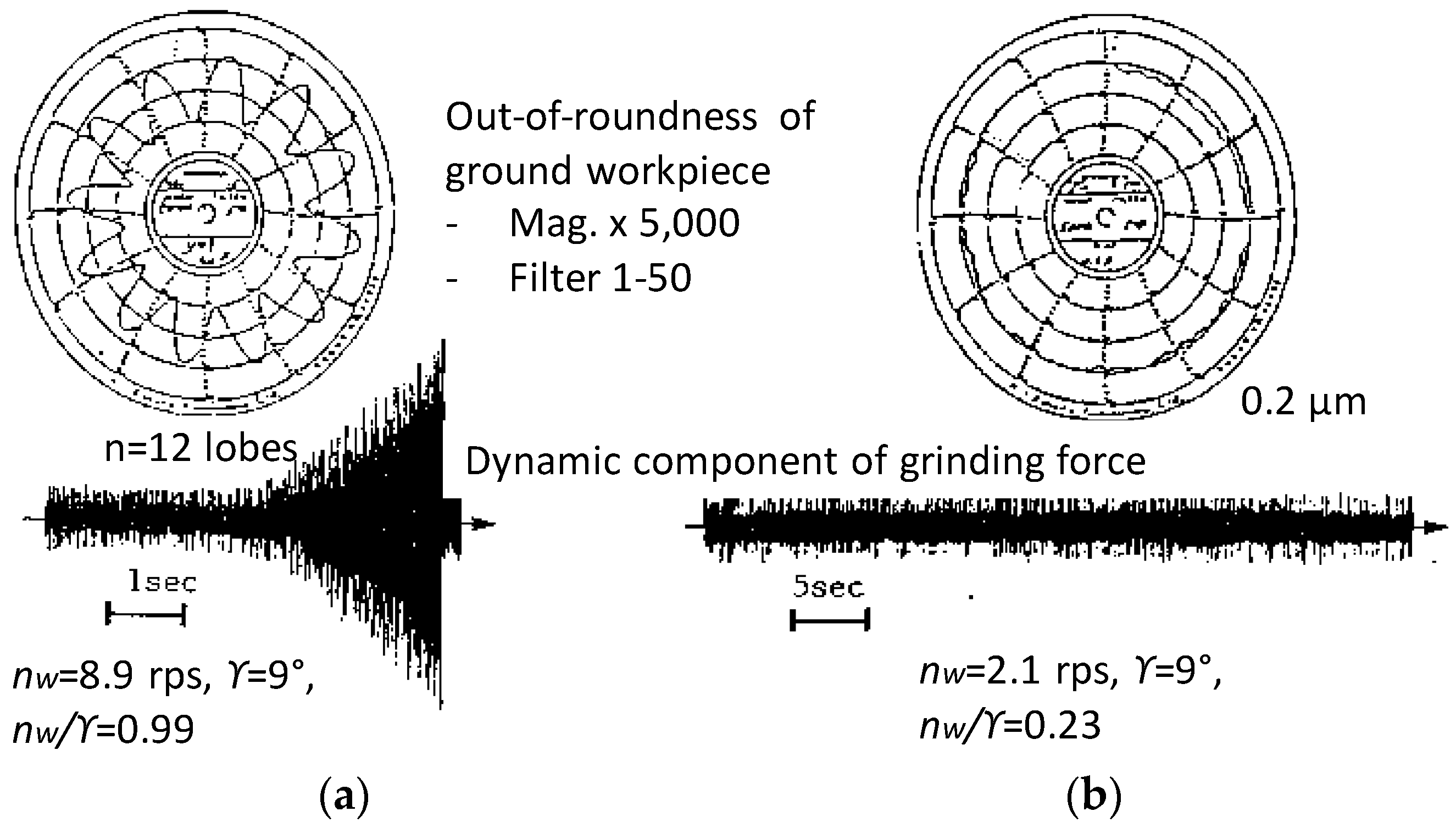
Figure 12.
Dynamic stability of centerless grinding system (experiment). (a) Unstable grinding process (chatter); (b) Stable grinding process.
Figure 12.
Dynamic stability of centerless grinding system (experiment). (a) Unstable grinding process (chatter); (b) Stable grinding process.

Figure 13.
Dynamic system stability diagram for Machine A. Conditions: b = 70 mm, k’w = 2 kN/mm·mm, k’cr = 0.3 kN/mm·mm, k’cs = 1 kN/mm·mm, kmr = 0.1 kN/μm, kms = 0.15 kN/μm, km1 = 0.3 kN/μm, fnr = 100 Hz, fns = 200 Hz, fn1 = 150 Hz, ζr = 0.05, ζs = 0.05, ζ1 = 0.05.
Figure 13.
Dynamic system stability diagram for Machine A. Conditions: b = 70 mm, k’w = 2 kN/mm·mm, k’cr = 0.3 kN/mm·mm, k’cs = 1 kN/mm·mm, kmr = 0.1 kN/μm, kms = 0.15 kN/μm, km1 = 0.3 kN/μm, fnr = 100 Hz, fns = 200 Hz, fn1 = 150 Hz, ζr = 0.05, ζs = 0.05, ζ1 = 0.05.

Figure 14.
Chatter zones on (n·γ–n·nw) diagram. (a) Grinding machine A; (b) Grinding machine B.

Figure 15.
Dynamic system stability criterion for machine A. (a) Chatter zones confirmed by grinding tests; (b) Dynamic system stability criterion.
Figure 15.
Dynamic system stability criterion for machine A. (a) Chatter zones confirmed by grinding tests; (b) Dynamic system stability criterion.
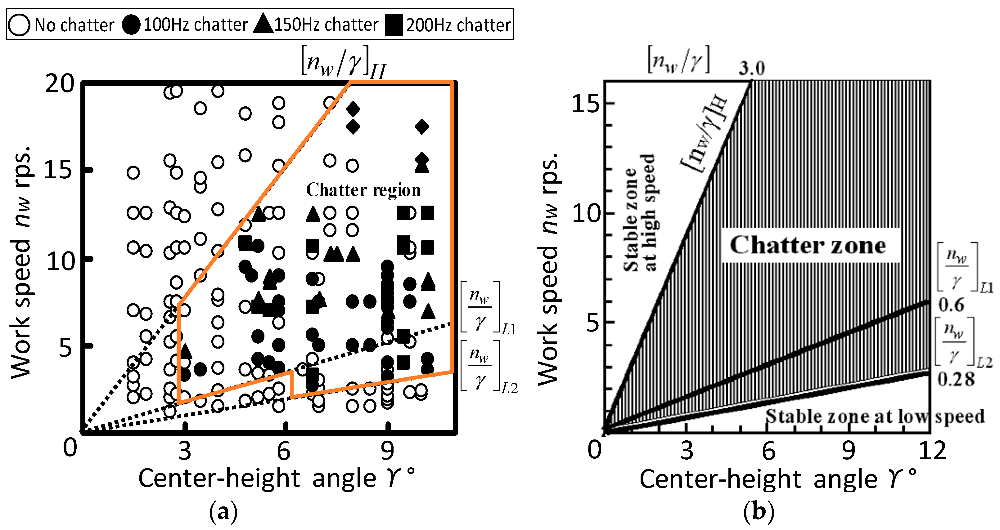
Figure 16.
Dynamic system stability criterion for machine B. (a) Chatter zones on (n·γ–n·nw) diagram; (b) Chatter zones on (γ–nw) chart.
Figure 16.
Dynamic system stability criterion for machine B. (a) Chatter zones on (n·γ–n·nw) diagram; (b) Chatter zones on (γ–nw) chart.

Figure 17.
Chatter free zones on γ–Nr chart. KH: High speed chatter-free zone, KL1, KL2: Low speed chatter-free zones.
Figure 17.
Chatter free zones on γ–Nr chart. KH: High speed chatter-free zone, KL1, KL2: Low speed chatter-free zones.
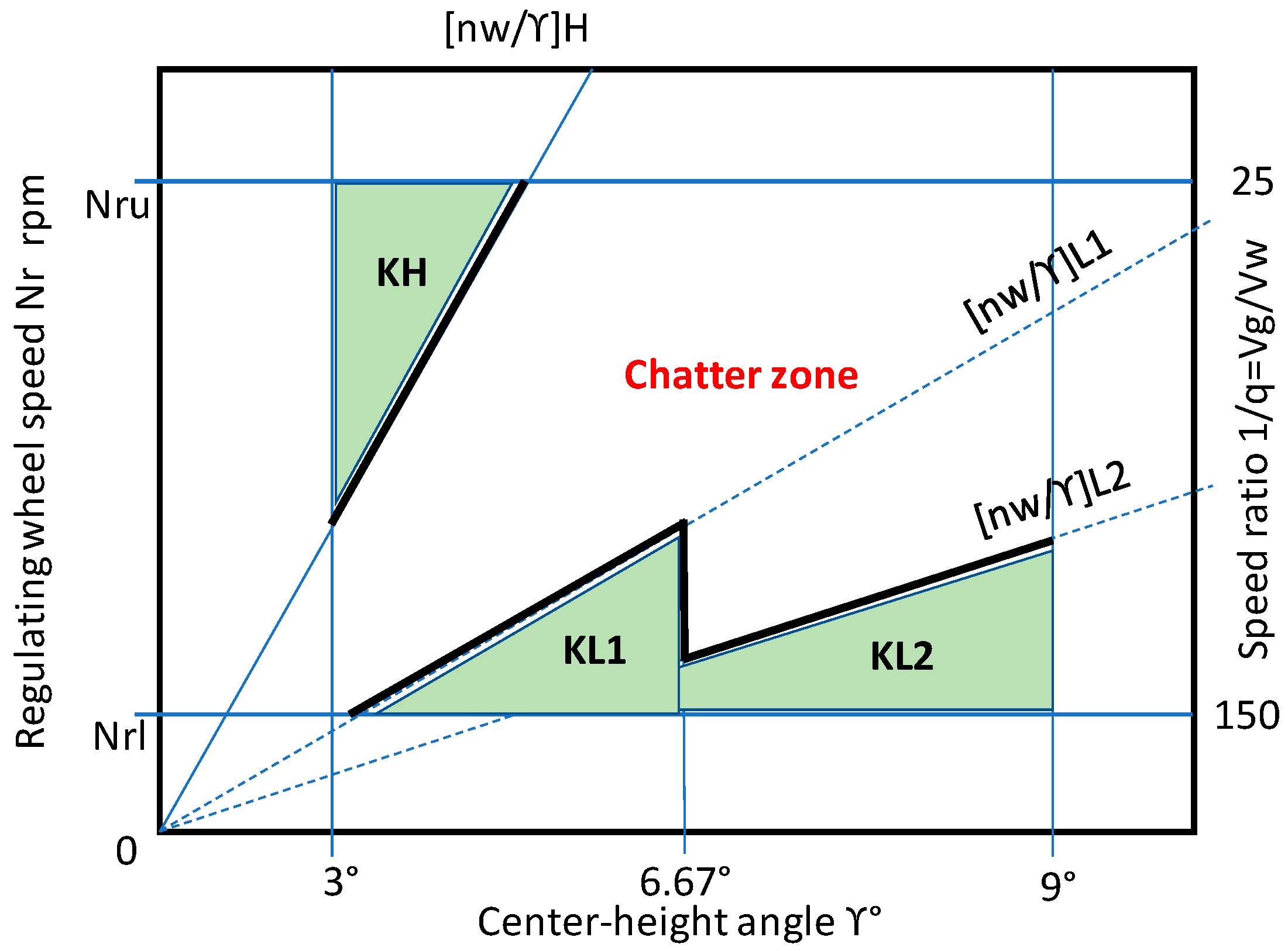
Figure 18.
Structure of the model for determining the optimum setup condition

Figure 19.
Flow chart of developed model “Opt-Setup Master”.


Table 1.
Input information and parameters referred to data bank.
| Inputs | Action | Parameters Referred to Data Bank |
|---|---|---|
| Machine name | Select | Machine specifications, Machine dynamic characteristics (Natural frequencies, damping ratios) |
| Workpiece shape | Select | Cylindrical (CYD), Tapered (TPD), Spherical (SRL), Multi-stepped (STD) |
| Workpiece part-number | Select | Dimensions (diameter, length, etc.), profile |
| GW diameter | Measure | New, worn, measured |
| RW diameter | Measure | New, worn, measured |
| RW dresser type and dress lead | Select | Single point dress, Rotary dress, Friction coefficient of RW |
| Blade availability | Select | Blade angle θ, blade thickness t |
Table 2.
Constraints of setup parameters.
| Setup Parameters | Symbol | Unit. | Min. | Max. | Typical |
|---|---|---|---|---|---|
| Range of speed ratio | 1/q = Vg/Vw | - | 25 | 150 | 100 |
| Range of blade angle | θ | ° | 15 | 45 | 30 |
| Range of Center-height angle | γ | ° | 3 | 9 | 6.67 |
| Range of regulating wheel speed | Nr | rpm | 15 | 100 | 50 |
| Range of GW diameter | Dg | mm | 375 | 455 | 450 |
| Range of RW diameter | Dr | mm | 275 | 350 | 345 |
| Range of Workpiece diameter | Dw | mm | 5 | 100 | 40 |
| Grinding wheel speed in revolution | Ng | rpm | 1260 | 2300 | 1890 |
| Grinding speed | Vg | m/s | 30 | 45 | 45 |
Table 3.
Performance Index (PI) functions.
| Process Aim | PI Function | Weighting Factors | ||||
|---|---|---|---|---|---|---|
| A | B | C | D | E | ||
| Accuracy | PIa = A × I θ − 27.5 I + B × I γ − 6.67 I + C × I Nr − 50 I + D × FL + E × STYP | 0.2 | 2 | 0.1 | 0.01 | 2 |
| Productivity | PIr = A × I θ − 45 I + B × I γ − 5.15 I + C × I Nr − 50 I + D × FL + E × STYP | 0.1 | 2 | 0.12 | 0.5 | 2 |
θ: Blade angle; γ: Center-height angle; Nr: RW speed in rpm; FL: KL1 = 0, KL2 = 0.5, KH = 1, STYP: (RW + B) GRSC = −1, RW − GRSC= 0, B − GRSC = +1.
Table 4.
Examples of outputs from Opt-Setup Master.
| Priority | Optimum Set Up Conditions | Engineering Parameter | Stability Parameters | ||||||||
|---|---|---|---|---|---|---|---|---|---|---|---|
| Ranking | Blade Angle | Blade Thickness | Center-Height | RW Speed | CH Angle | Work Speed | 1/q Ratio | (nw/γ) | Stable Zone | RW − GRSC | Blade − GRSC |
| No. | θ (°) | t (mm) | CH (mm) | Nr (rpm) | γ (°) | nw (rps) | Vg/Vw | (1/s) | KH/KL1/KL2 | 180/γ | (90 − θ − β)/γ |
| 1 | 40.3 | 20 | 12.68 | 41.8 | 6.68 | 6.1 | 25 | 0.91 | KL2 | 27 | 7 |
| 2 | 40.3 | 20 | 12.66 | 83.5 | 6.67 | 12.2 | 25 | 1.83 | KL1 | 27 | 7 |
| 3 | 40.3 | 20 | 13.67 | 45.1 | 7.2 | 6.58 | 25 | 0.91 | KL2 | 27 | 6.5 |
Conditions: Machine B, Process aim: accuracy, Work: cylindrical Dia.40 × L60 mm.
Table 5.
The optimum setup conditions provided by the Opt-Setup Master for the grinding of cylindrical workpieces with different machines A and B.
Table 5.
The optimum setup conditions provided by the Opt-Setup Master for the grinding of cylindrical workpieces with different machines A and B.
| Case No. | Work Dia.x L. | Machine | Blade Angle | C-H Angle | RW Speed | Chatter DSSC | Chatter Stable Zone | RW − GRSC | Blade – GRSC |
|---|---|---|---|---|---|---|---|---|---|
| mm | A/B | θ (°) | γ (°) | Nr (rpm) | (nw/γ) | KH/KL1/KL2 | 180/γ | (90 − θ − β)/γ | |
| 1 | 10 × 20 | A | 27.5 | 6.67 | 38.6 | 3.37 | KH | 27 | 9 |
| 2 | B | 27.5 | 6.67 | 64.1 | 5.61 | KH | 27 | 9 | |
| 3 | 20 × 30 | A | 27.5 | 6.67 | 77.1 | 3.37 | KH | 27 | 9 |
| 4 | B | 27.5 | 6.67 | 41.8 | 1.83 | KL1 | 27 | 9 | |
| 5 | 30 × 50 | A | 40.3 | 6.67 | 14.6 | 0.43 | KL1 | 27 | 7 |
| 6 | B | 40.3 | 6.67 | 62.7 | 1.83 | KL1 | 27 | 7 | |
| 7 | 40 × 60 | A | 40.30 | 6.67 | 19.4 | 0.43 | KL1 | 27 | 7 |
| 8 | B | 40.30 | 6.68 | 41.8 | 0.91 | KL2 | 27 | 7 | |
| 9 | 50 × 70 | A | 40.30 | 6.67 | 24.3 | 0.43 | KL1 | 27 | 7 |
| 10 | B | 40.30 | 6.68 | 52.3 | 0.91 | KL2 | 27 | 7 | |
| 11 | 60 × 80 | A | 40.30 | 6.67 | 29.1 | 0.43 | KL1 | 27 | 7 |
| 12 | B | 40.30 | 6.68 | 62.7 | 0.91 | KL2 | 27 | 7 |
Condition: GW φ453 mm, Rubber bonded RW φ350 mm, µr0 = 0.4, Available blade θ = 27.5°, 40.3°.
© 2017 by the author. Licensee MDPI, Basel, Switzerland. This article is an open access article distributed under the terms and conditions of the Creative Commons Attribution (CC BY) license (http://creativecommons.org/licenses/by/4.0/).
Share and Cite
MDPI and ACS Style
Hashimoto, F. Model Development for Optimum Setup Conditions that Satisfy Three Stability Criteria of Centerless Grinding Systems. Inventions 2017, 2, 26. https://doi.org/10.3390/inventions2040026
AMA Style
Hashimoto F. Model Development for Optimum Setup Conditions that Satisfy Three Stability Criteria of Centerless Grinding Systems. Inventions. 2017; 2(4):26. https://doi.org/10.3390/inventions2040026
Chicago/Turabian StyleHashimoto, Fukuo. 2017. "Model Development for Optimum Setup Conditions that Satisfy Three Stability Criteria of Centerless Grinding Systems" Inventions 2, no. 4: 26. https://doi.org/10.3390/inventions2040026