Experimental Analysis for the Use of Sodium Dodecyl Sulfate as a Soluble Metal Cutting Fluid for Micromachining with Electroless-Plated Micropencil Grinding Tools

 ,
,
Abstract
:1. Introduction
2. Materials and Methods
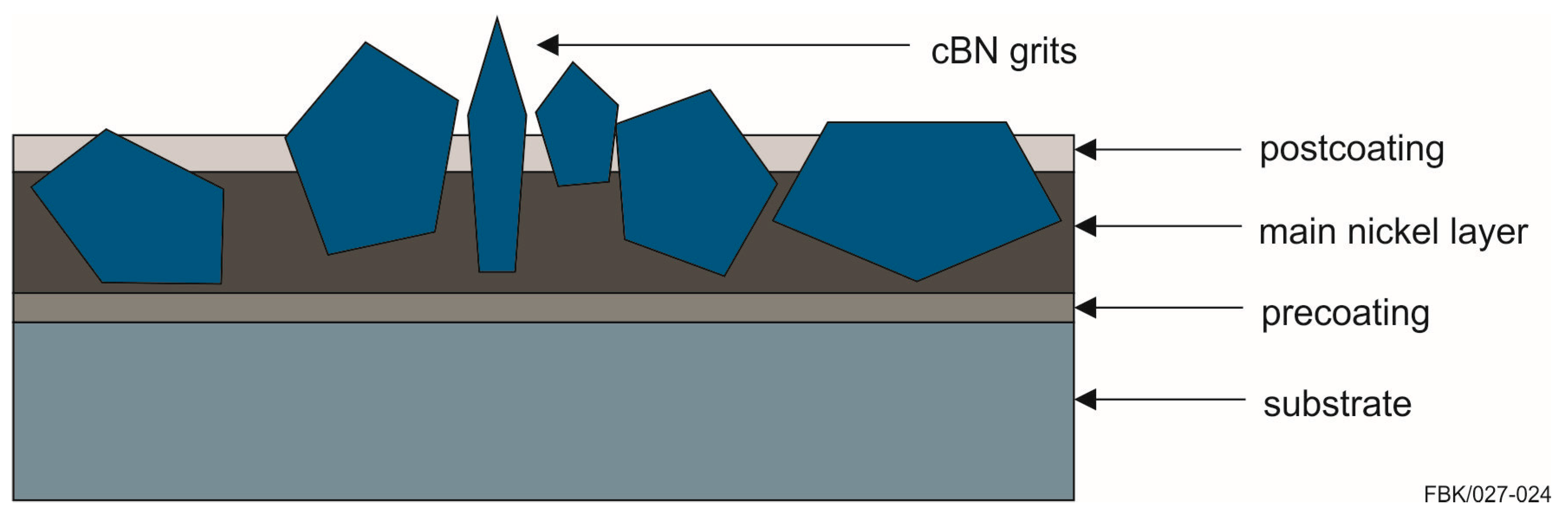
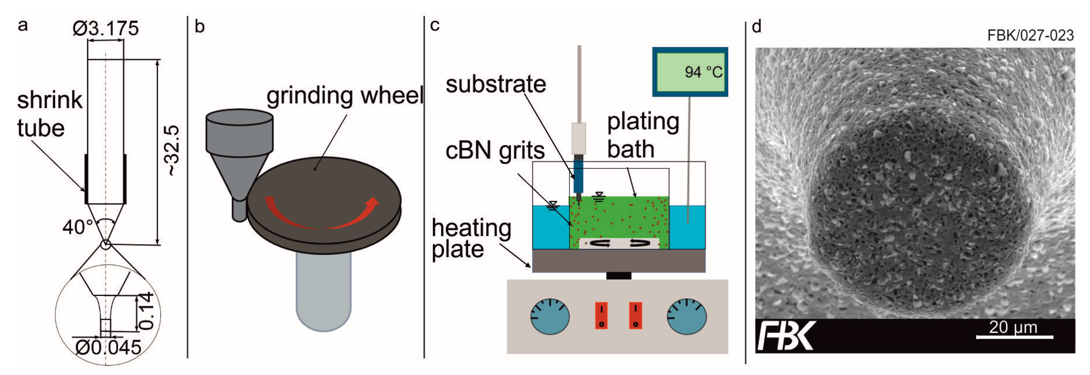
2.1. Micropencil Grinding Tools
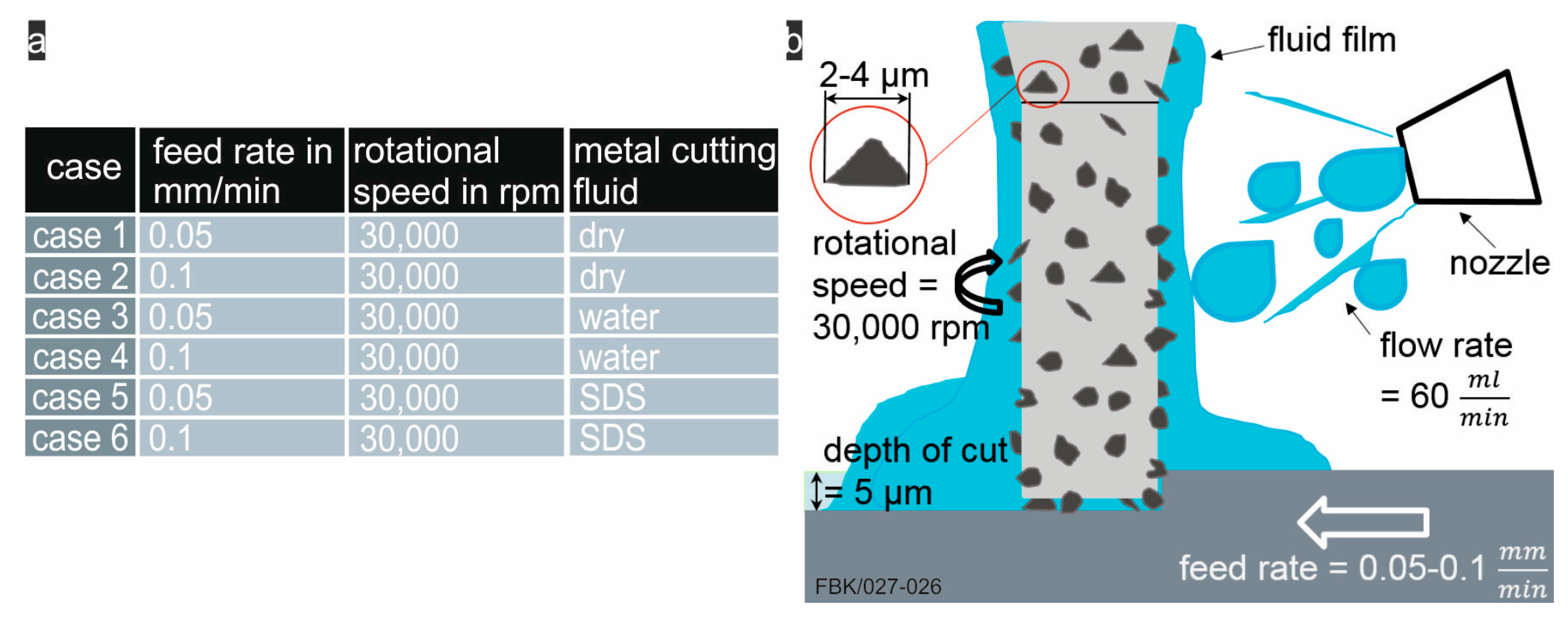
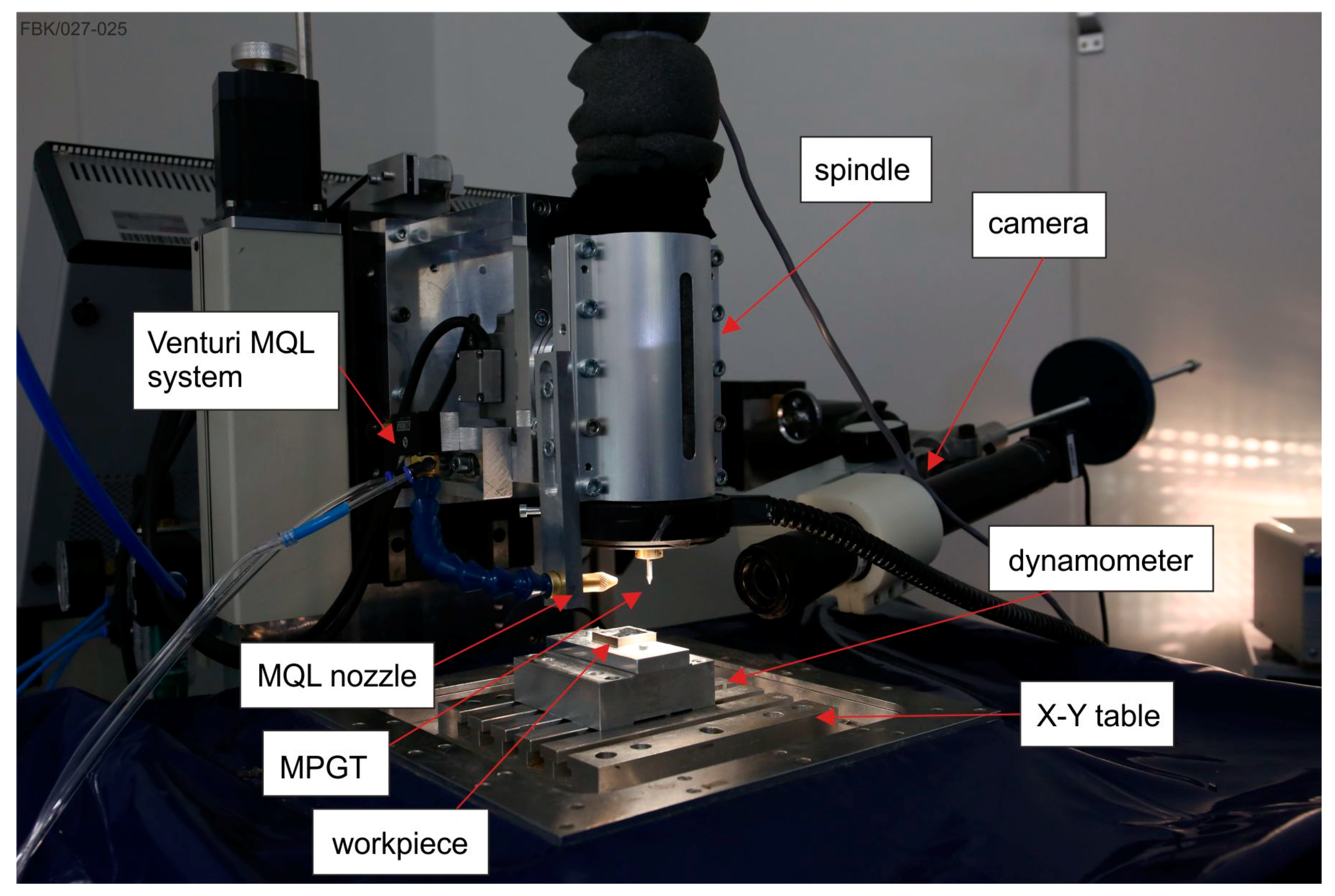
2.2. Experimental Setup
2.3. Experimental Procedure
3. Results
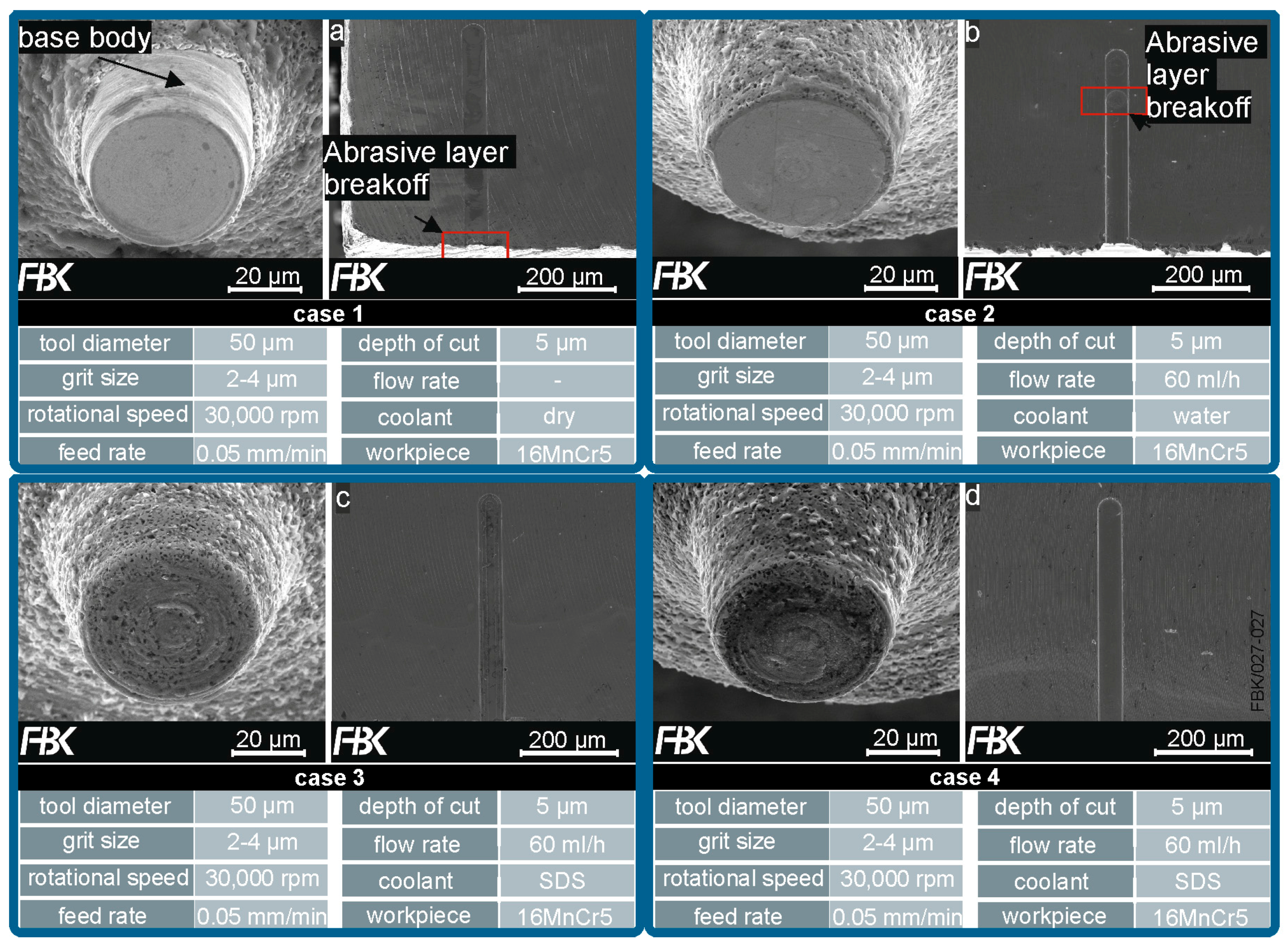
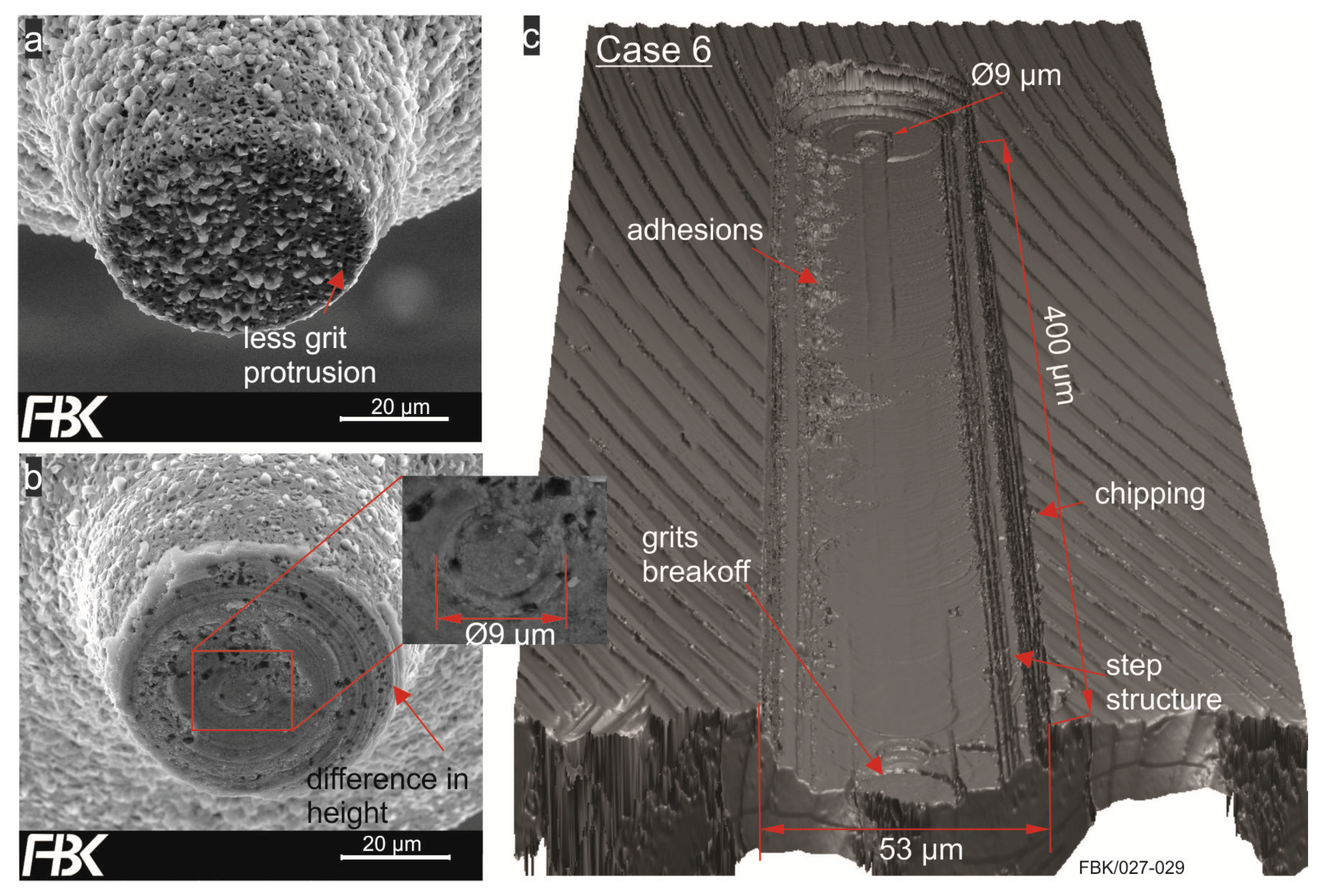
3.1. Tool Wear
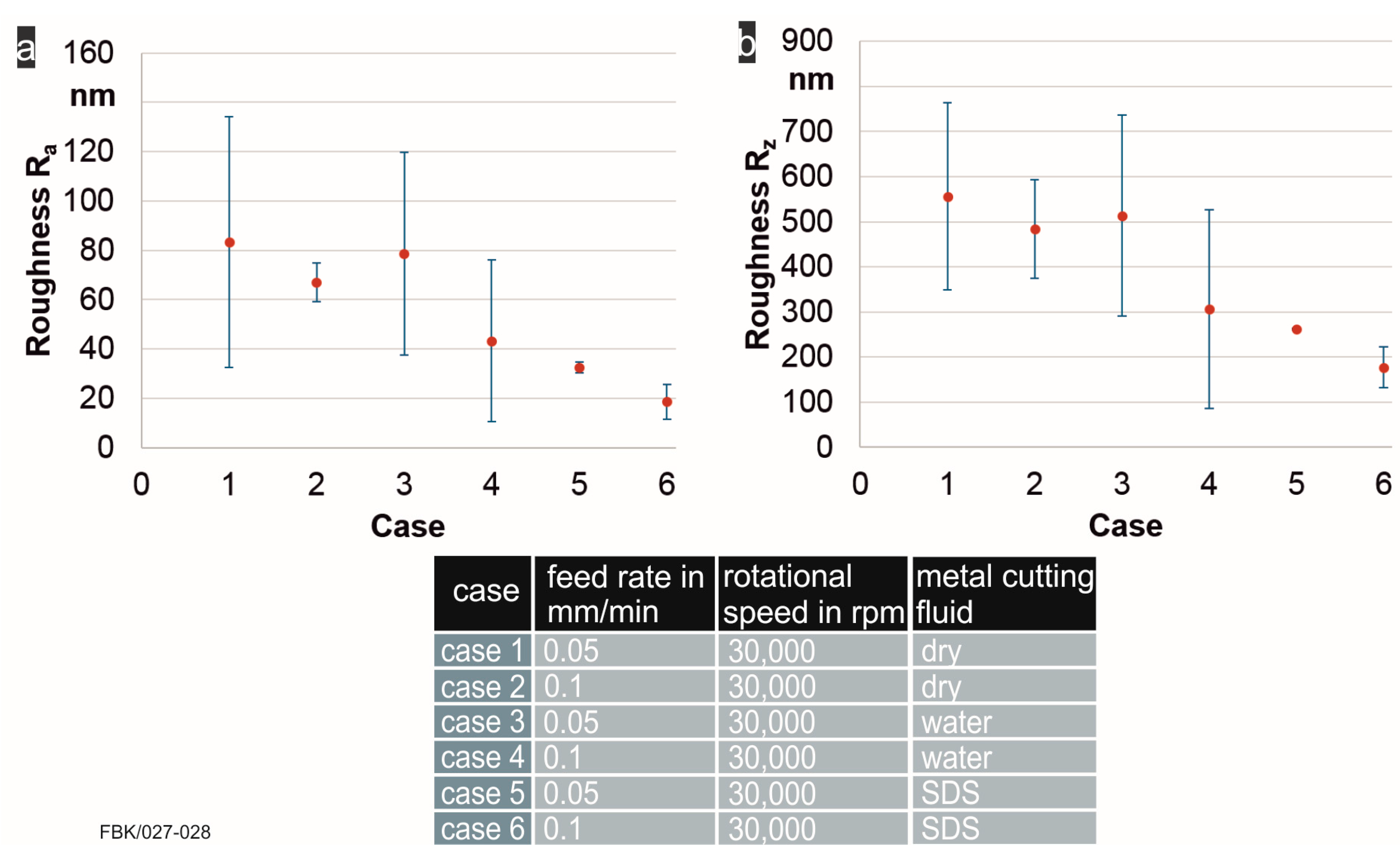
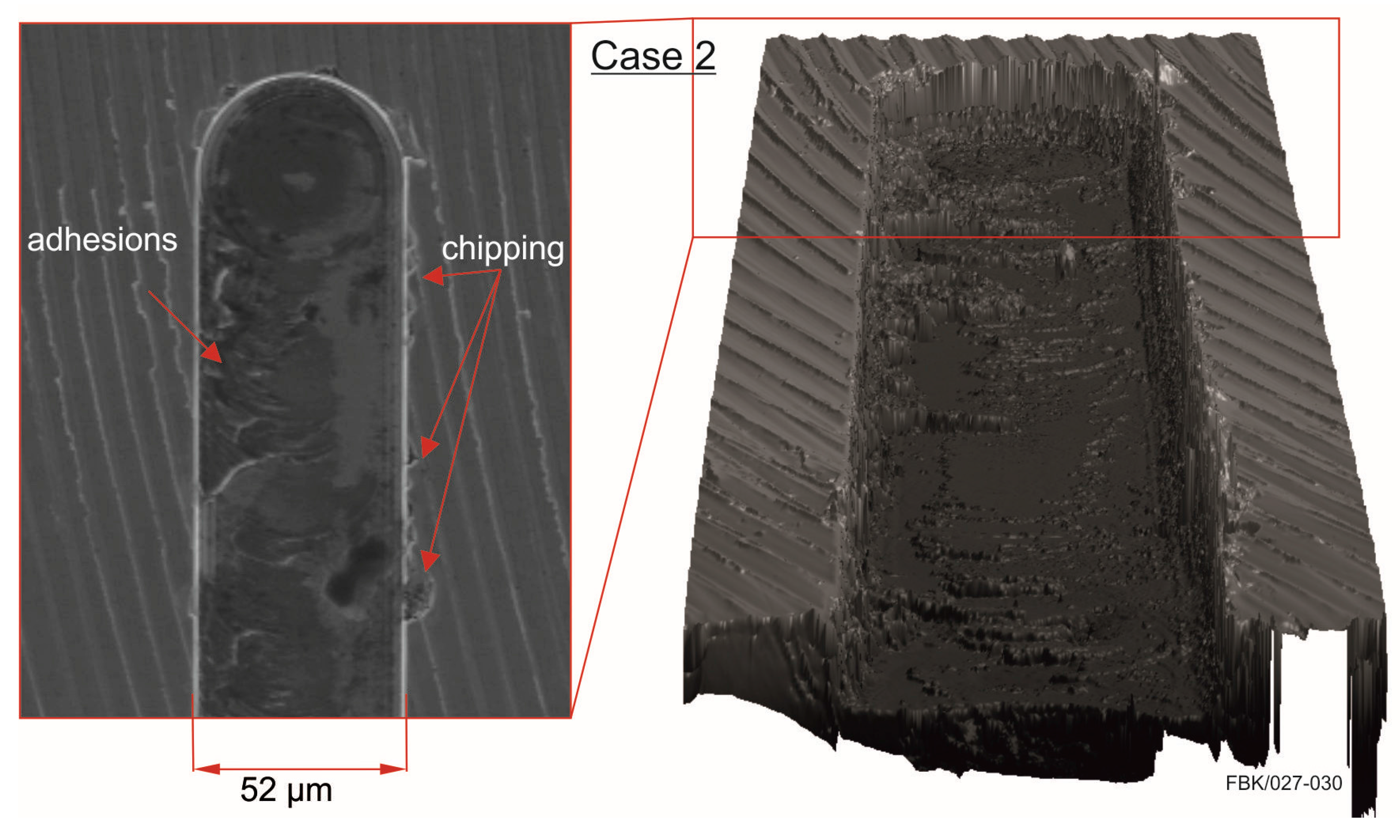
3.2. Structure Analysis
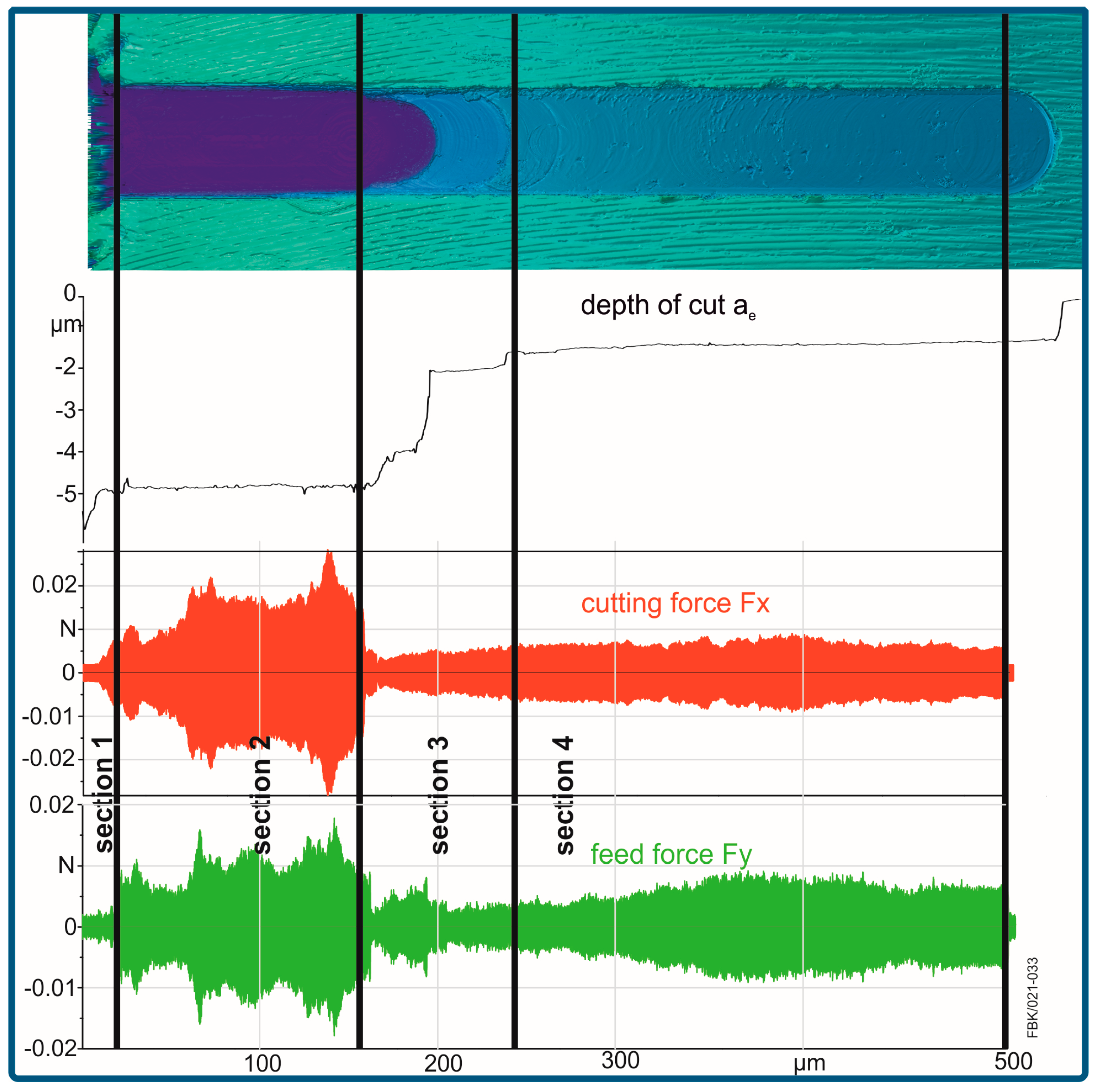
3.3. Force Measurements
4. Conclusions and Outlook
Acknowledgments
Author Contributions
Conflicts of Interest
References
- Feng, J. Microgrinding of Ceramic Materials. Ph.D. Thesis, Michigan Technological University, Houghton, MI, USA, 2010. [Google Scholar]
- Pratap, A.; Patra, K.; Dyakonov, A.A. Manufacturing miniature products by micro grinding: A review. Procedia Eng. 2016, 150, 969–974. [Google Scholar] [CrossRef]
- Wensink, H. Fabrication of Microstructures by Powder Blasting. Ph.D. Thesis, University of Twente, Enschede, The Netherlands, 2002. [Google Scholar]
- Engmann, J. Galvanisch Gebundene Mikroschleifstifte. Entwicklung, Herstellung und Einsatz, Als Ms. Gedr; Produktionstechnische Berichte aus dem FBK 01/2011; Technischen Universität Kaiserslautern: Kaiserslautern, Germany, 2011. [Google Scholar]
- Reichenbach, I.G.; Aurich, J.C. Untersuchung der oberflächengüte beim mikrofräsen—einfluss von prozessparametern und einstellwinkel der nebenschneide bei 48 μm mikroschaftwerkzeugen. Wt Werkstattstechnik Online 2013, 103/11–12, 847–852. [Google Scholar]
- Brinksmeier, E.; Mutlugünes, Y.; Klocke, F.; Aurich, J.C.; Shore, P.; Ohmori, H. Ultra precision grinding. CIRP Ann. Manuf. Technol. 2010, 59, 652–671. [Google Scholar] [CrossRef]
- Hoffmeister, H.-W.; Hlavac, M. Schleifen von Mikrostrukturen. In Tagungsband des 10. Feinbearbeitungskolloqiums in Braunschweig; Vulkan-Verlag: Essen, Germany, 2002; pp. 7.1–7.24. [Google Scholar]
- Setti, D.; Sinha, M.K.; Ghosh, S.; Rao, P.V. Performance evaluation of Ti–6Al–4V grinding using chip formation and coefficient of friction under the influence of nanofluids. Int. J. Mach. Tools Manuf. 2015, 88, 237–248. [Google Scholar] [CrossRef]
- Klocke, F. Manufacturing Processes 2: Grinding, Honing, Lapping; Springer: Berlin, Germany, 2009. [Google Scholar]
- Brinksmeier, E.; Heinzel, C.; Wittmann, M. Friction, cooling and lubrication in grinding. CIRP Ann. Manuf. Technol. 1999, 48, 581–598. [Google Scholar] [CrossRef]
- Dornfeld, D.; Min, S.; Takeuchi, Y. Recent advances in mechanical micro-machinability of copper 101 using tungsten carbide micro-end mills. Int. J. Mach. Tools Manuf. 2006, 55, 745–768. [Google Scholar]
- Brudek, G. Beiträge zur Prozessanalyse in der Mikrozerspanung. Insbesondere für das Mikrofräsen; Berichte aus dem Institut für Konstruktions- und Fertigungstechnik Bd. 8; Shaker: Aachen, Germany, 2007. [Google Scholar]
- Nam, J.S.; Kim, D.H.; Chung, H.; Lee, S.W. Optimization of environmentally benign micro-drilling process with nanofluid minimum quantity lubrication using response surface methodology and genetic algorithm. J. Clean. Prod. 2015, 102, 428–436. [Google Scholar] [CrossRef]
- Pham, M.Q.; Yoon, H.S.; Khare, V.; Ahn, S.H. Evaluation of ionic liquids as lubricants in micro milling-process capability and sustainability. J. Clean. Prod. 2014, 76, 167–173. [Google Scholar] [CrossRef]
- Smulders, E.; Rybinski, W.-V.; Sung, E.; Rähse, W.; Steber, J.; Wiebel, F. Nordskog: Ullmann’s Encyclopedia of Industrial Chemistry; Wiley-VCH Verlag GmbH & Co. KGaA: Weinheim, Germany, 2000. [Google Scholar]
- DIN EN ISO 3878, Hardmetals, Vickers Hardness Test, Identical with ISO 3878:1983; International Organization for Standardization: Geneva, Switzerland, 1991.
- Arrabiyeh, P.A.; Kirsch, B.; Aurich, J.C. Development of micro pencil grinding tools via an electroless plating process. J. Micro Nano Manuf. 2017, 5, 011002. [Google Scholar] [CrossRef]
- Lin, K.L.; Hwang, J.W. Effect of thiourea and lead acetate on the deposition of electroless nickel. Mater. Chem. Phys. 2002, 76, 204–211. [Google Scholar] [CrossRef]
- Mallory, G.O.; Hajdu, J.B. Electroless Plating: Fundamentals and Applications; American Electroplaters & Surface Finishers Society: Orlando, FL, USA, 1990. [Google Scholar]
- Kirsch, B.; Bohley, M.; Arrabiyeh, P.A.; Aurich, J.C. Application of ultra-small micro grinding and micro milling tools: Possibilities and limitations. Micromachines 2017, 8, 261. [Google Scholar] [CrossRef]
- DIN EN ISO 6507-1:2006-03 Metallic Materials—Vickers Hardness Test—Part 1: Test Method; International Organization for Standardization: Geneva, Switzerland, 2006.
- Granta Design Ltd. CES EduPack Software; Granta Design Ltd.: Cambridge, UK, 2012. [Google Scholar]
- DIN EN ISO 16610-21:2013-06 Geometrical Product Specifications (GPS)—Filtration—Part 21: Linear Profile Filters: Gaussian Filters; International Organization for Standardization: Geneva, Switzerland, 2012.
- DIN EN ISO 11562:1998-09 Geometrical Product Specifications (GPS)—Surface Texture: Profile Method—Metrological Characteristics of Phase Correct Filters; International Organization for Standardization: Geneva, Switzerland, 1997.
- DIN EN ISO 4287:2010-07 Geometrical Product Specifications (GPS)—Surface Texture: Profile Method—Terms, Definitions and Surface Texture Parameters; International Organization for Standardization: Geneva, Switzerland, 2009.
- DIN EN ISO 4288:1998-08 Geometrical Product Specifications (GPS)—Surface Texture: Profile Method—Rules and Procedures for the Assessment of Surface Texture; International Organization for Standardization: Geneva, Switzerland, 1997.


| Component | Concentration in g/L |
|---|---|
| Nickel sulfate (NiSO4·6H2O) | 30 |
| Sodium hypophosphite (NaH2PO2) | 20 |
| Sodium acetate (C2H3NaO2) | 20 |
| Thiourea (CH4N2S) | 0.0004 |
| Hydrochloric acid (HCl) | Adapted to a pH value of 5.2–5.4 |
| cBN grits | 4 |
© 2017 by the authors. Licensee MDPI, Basel, Switzerland. This article is an open access article distributed under the terms and conditions of the Creative Commons Attribution (CC BY) license (http://creativecommons.org/licenses/by/4.0/).
Share and Cite
Arrabiyeh, P.A.; Bohley, M.; Ströer, F.; Kirsch, B.; Seewig, J.; Aurich, J.C. Experimental Analysis for the Use of Sodium Dodecyl Sulfate as a Soluble Metal Cutting Fluid for Micromachining with Electroless-Plated Micropencil Grinding Tools. Inventions 2017, 2, 29. https://doi.org/10.3390/inventions2040029
Arrabiyeh PA, Bohley M, Ströer F, Kirsch B, Seewig J, Aurich JC. Experimental Analysis for the Use of Sodium Dodecyl Sulfate as a Soluble Metal Cutting Fluid for Micromachining with Electroless-Plated Micropencil Grinding Tools. Inventions. 2017; 2(4):29. https://doi.org/10.3390/inventions2040029
Chicago/Turabian StyleArrabiyeh, Peter A., Martin Bohley, Felix Ströer, Benjamin Kirsch, Jörg Seewig, and Jan C. Aurich. 2017. "Experimental Analysis for the Use of Sodium Dodecyl Sulfate as a Soluble Metal Cutting Fluid for Micromachining with Electroless-Plated Micropencil Grinding Tools" Inventions 2, no. 4: 29. https://doi.org/10.3390/inventions2040029