A New Control Strategy for an Electronic Differential System for Urban Electric Vehicles

 ,
,
Abstract
:
1. Introduction
1.1. Background and Motivation
1.2. Related Studies
2. Proposed Approach
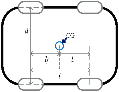
2.1. Model Construction
2.2. System Structure
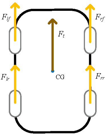
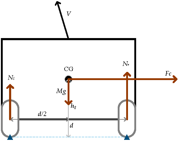
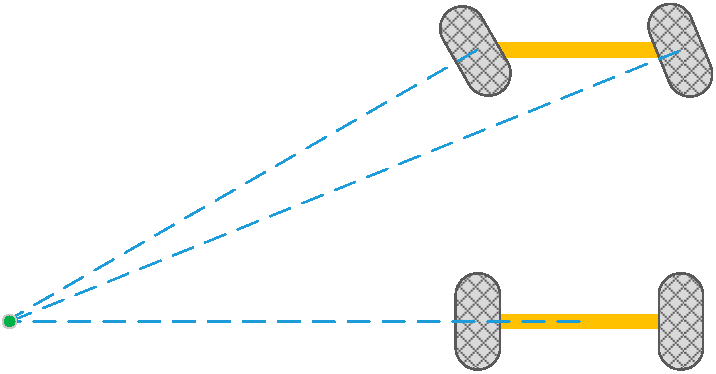
2.3. Longitudinal Vehicle Dynamics
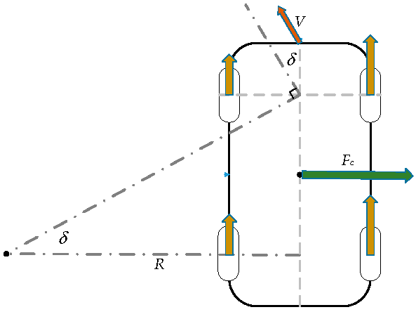
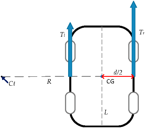
2.4. Distribution Method
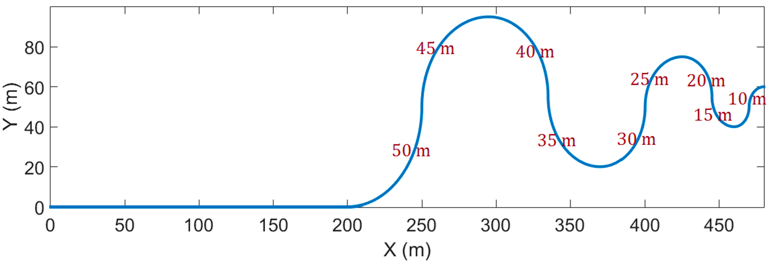
3. Results
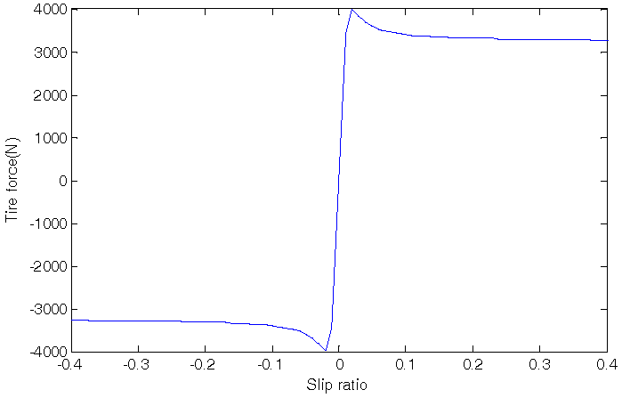
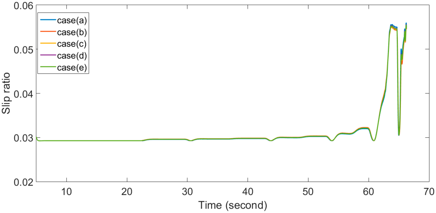
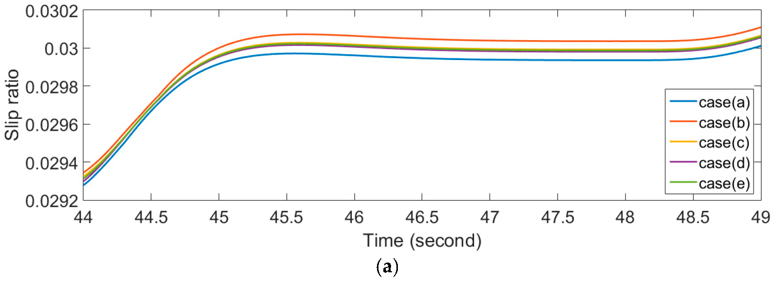
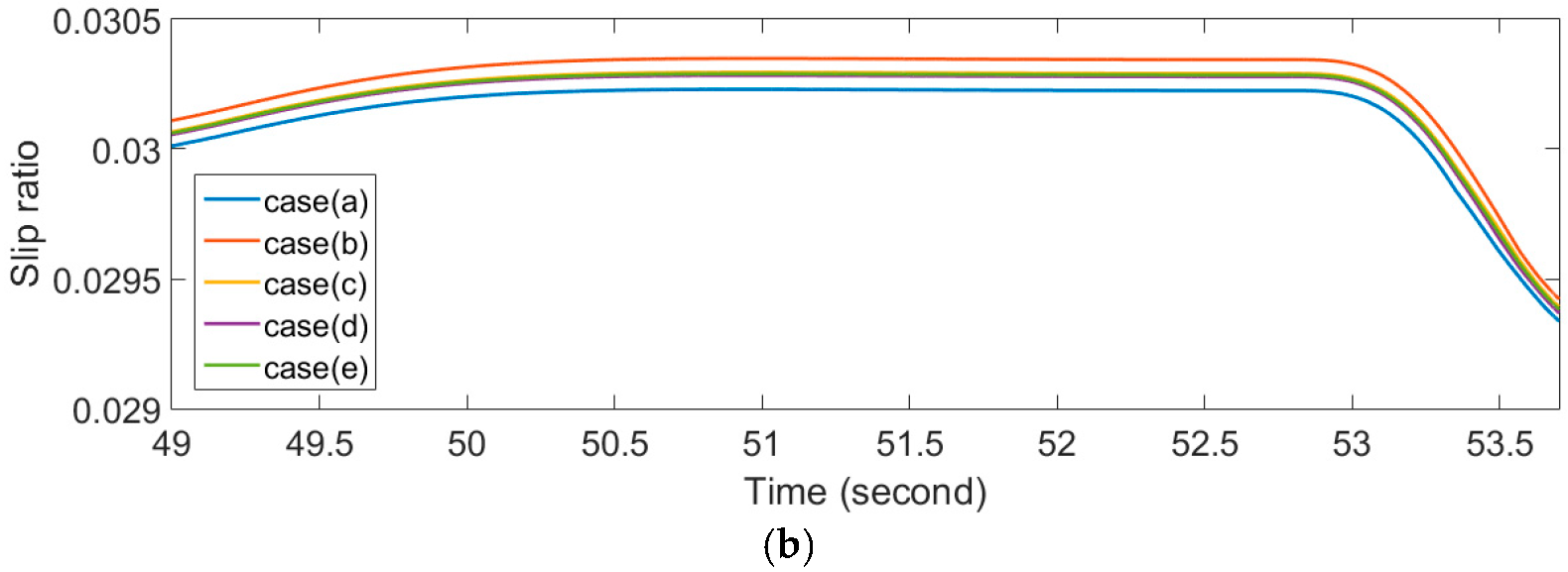
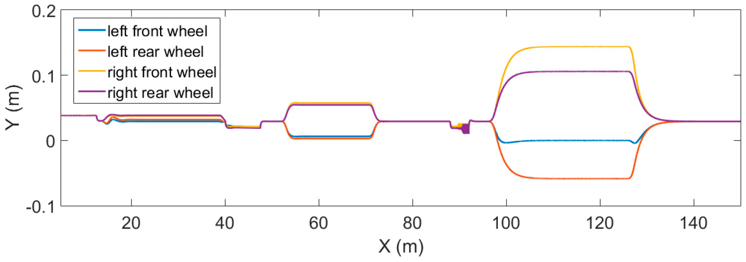
3.1. Slip Ratio
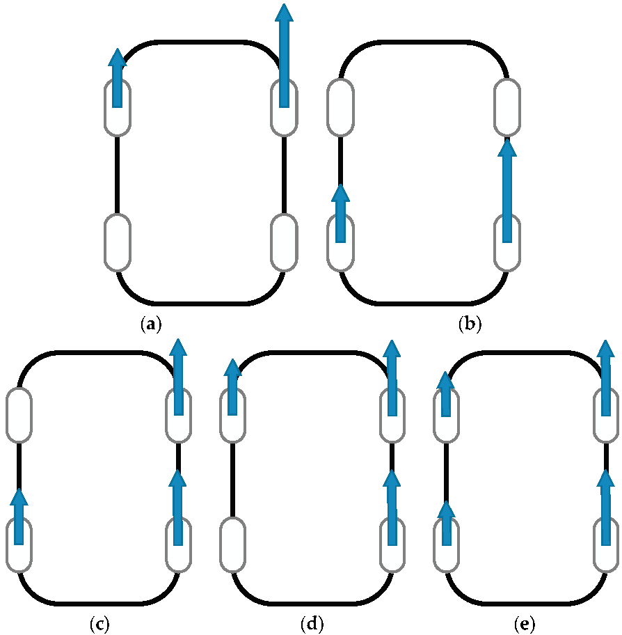
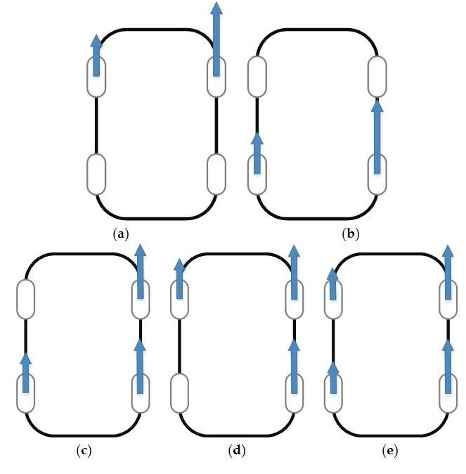
3.2. Torque Distribution
4. Conclusions
Acknowledgments
Author Contributions
Conflicts of Interest
References
- Jayakumar, A.; Chalmers, A.; Lie, T.T. Review of prospects for adoption of fuel cell electric vehicles in New Zealand. IET Electr. Syst. Transp. 2017, 7, 259–266. [Google Scholar] [CrossRef]
- Chan, C.C.; Chau, K.T. Modern Electric Vehicle Technology; Oxford University Press: London, UK, 2001; ISBN 978-0198504160. [Google Scholar]
- Folgado, J.; Valtchev, S.S.; Coito, F. Electronic differential for electric vehicle with evenly split torque. In Proceedings of the 2016 IEEE International Power Electronics and Motion Control Conference (PEMC), Varna, Bulgaria, 25–28 September 2016; pp. 1204–1209. [Google Scholar]
- Zhao, Y.E.; Zhang, J.W.; Guan, X.Q. Modeling and simulation of electronic differential system for an electric vehicle with two-motor-wheel drive. In Proceedings of the 2009 IEEE Intelligent Vehicles Symposium, Xi’an, China, 3–5 June 2009; pp. 1209–1214. [Google Scholar]
- Wu, X.; Xu, M.; Wang, L. Differential speed steering control for four-wheel independent driving electric vehicle. Int. J. Mater. Mech. Manuf. 2013, 1, 355–359. [Google Scholar]
- STARSHIP. Available online: https://www.starship.xyz/ (accessed on 3 December 2017).
- Kiva Systems. Available online: http://www.mwpvl.com/html/kiva_systems.html (accessed on 3 December 2017).
- Yıldırım, M.; Öksüztepe, E.; Tanyeri, B.; Kürüm, H. Design of Electronic Differential System for an Electric Vehicle with in-wheel motor. In Proceedings of the 2016 IEEE Power and Energy Conference at Illinois (PECI), Urbana, IL, USA, 19–20 February 2016; pp. 1–5. [Google Scholar]
- Zhao, S.; Zhao, J.S.; Feng, Z.J. Design of a Pair of Noncircular Gears Meeting Ackermann Steering Principle. In Proceedings of the 2011 International Conference on Consumer Electronics, Communications and Networks (CECNet), Xianning, China, 11–13 March 2011; pp. 217–221. [Google Scholar]
- Yin, D.; Sun, N.; Shan, D.; Hu, J.-S. A multiple data fusion approach to wheel slip control for decentralized electric vehicles. Energies 2017, 10, 461. [Google Scholar] [CrossRef]
- Hu, J.; Wu, J.; Peng, H.; Peng, Q.; Huang, Q. Application of Fuzzy Logic Algorithm for Optimization of Control Strategy in Electric Vehicles. In Proceedings of the 2017 IEEE 2nd Advanced Information Technology, Electronic and Automation Control Conference (IAEAC), Chongqing, China, 25–26 March 2017; pp. 2042–2045. [Google Scholar]
- Mirzaei, M.; Mirzaeinejad, H. Fuzzy scheduled optimal control of integrated vehicle braking and steering systems. IEEE/ASME Trans. Mechatron. 2017, 22, 2369–2379. [Google Scholar] [CrossRef]
- Nam, K.; Fujimoto, H.; Hori, Y. Lateral stability control of in-wheel-motor-driven electric vehicles based on sideslip angle estimation using lateral tire force sensors. IEEE Trans. Veh. Technol. 2012, 61, 1972–1985. [Google Scholar]
- Hu, J.S.; Wang, Y.; Fujimoto, H.; Hori, Y. Robust yaw stability control for in-wheel motor electric vehicles. IEEE/ASME Trans. Mechatron. 2017, 22, 1360–1370. [Google Scholar] [CrossRef]
- Pacejka, H.B.; Bakker, E. The magic formula tyre model. Veh. Syst. Dyn. 1992, 21, 1–18. [Google Scholar] [CrossRef]
- Rajamani, R. Vehicle Dynamics and Control, 2nd ed.; Springer: New York, NY, USA, 2012; pp. 87–98, 359–366. ISBN 978-1-4614-1432-2. [Google Scholar]
- Wang, Y.; Fujimoto, H.; Hara, S. Torque distribution-based range extension control system for longitudinal motion of electric vehicles by LTI modeling with generalized frequency variable. IEEE/ASME Trans. Mechatron. 2016, 21, 443–452. [Google Scholar]
- Fujimoto, H.; Harada, S. Model-based range extension control system for electric vehicles with front and rear driving—Braking force distributions. IEEE Trans. Ind. Electron. 2015, 62, 3245–3254. [Google Scholar] [CrossRef]


| Vehicle mass M | 1650 kg |
| Wheelbase l | 3050 mm |
| Distance from CG to front axle tread lf | 1400 mm |
| Distance from CG to front axle tread lr | 1650 mm |
| Vehicle width d | 1880 mm |
| Gravity height hg | 530 mm |
| Wheel radius r | 727.2 mm |
© 2018 by the authors. Licensee MDPI, Basel, Switzerland. This article is an open access article distributed under the terms and conditions of the Creative Commons Attribution (CC BY) license (http://creativecommons.org/licenses/by/4.0/).
Share and Cite
Chang, Y.-C.; Lu, C.-Y.; Chen, W.-C.; Hu, J.-S.; Jiang, J.-F.; Chang, T.-K.; Wei, H.-Y. A New Control Strategy for an Electronic Differential System for Urban Electric Vehicles. Inventions 2018, 3, 19. https://doi.org/10.3390/inventions3010019
Chang Y-C, Lu C-Y, Chen W-C, Hu J-S, Jiang J-F, Chang T-K, Wei H-Y. A New Control Strategy for an Electronic Differential System for Urban Electric Vehicles. Inventions. 2018; 3(1):19. https://doi.org/10.3390/inventions3010019
Chicago/Turabian StyleChang, Yu-Chen, Chuan-Yi Lu, Wei-Chun Chen, Jia-Sheng Hu, Jinn-Feng Jiang, Tsu-Kun Chang, and Hung-Yuan Wei. 2018. "A New Control Strategy for an Electronic Differential System for Urban Electric Vehicles" Inventions 3, no. 1: 19. https://doi.org/10.3390/inventions3010019
APA StyleChang, Y.-C., Lu, C.-Y., Chen, W.-C., Hu, J.-S., Jiang, J.-F., Chang, T.-K., & Wei, H.-Y. (2018). A New Control Strategy for an Electronic Differential System for Urban Electric Vehicles. Inventions, 3(1), 19. https://doi.org/10.3390/inventions3010019