
DSP Processer-in-the-Loop Tests Based on Automatic Code Generation


1
School of Control Science and Engineering, Shandong University, Jinan 250061, China
2
State Key Laboratory of Automotive Simulation and Control, Jilin University, Changchun 130022, China
3
School of Information Science and Electrical Engineering, Shandong Jiaotong University, Jinan 250357, China
*
Author to whom correspondence should be addressed.
Inventions 2022, 7(1), 12; https://doi.org/10.3390/inventions7010012
Submission received: 18 November 2021
/
Revised: 29 December 2021
/
Accepted: 3 January 2022
/
Published: 11 January 2022
(This article belongs to the Collection Feature Innovation Papers)
Abstract
:The digital signal processing (DSP) processor-in-the-loop tests based on automatic code generation technology are studied. Firstly, the idea of model-based design is introduced, and the principle and method of embedded code automatic generation technology are analyzed by taking the automatic code generation of the DSP control algorithm for pulse width modulation (PWM) output as an example. Then, the control system model is established on MATLAB/Simulink. After verifying the model through simulation, the target board platform is established with DSP as the core processor, and the automatically generated code is tested by the processor-in-the-loop (PIL). The results show that the technology greatly shortens the development cycle of the project, improves the robustness and consistency of the control code, and can be widely used in the complex algorithm development process of the controller, from intelligent design and modeling to implementation.
1. Introduction
As is well known, due to the rapid development of modern industrial technology, product upgrading is changing with each passing day; at the same time, the requirements for product control performance are also becoming higher and higher. In recent decades, as the requirements for control redundancy and safety have become more demanding, the number of control codes of products has also become larger, such as modern automobiles, space shuttles, and aerospace ships, etc., in which there are codes at the level of one million lines or more [1,2]. Nowadays, more and more people are paying increasing attention to the intelligent network function when buying a car, such as automatic driving, intelligent operating system, perception fusion and artificial intelligence (AI) interaction, big data operation and vehicle over-the-air technology (OTA) capabilities, and vehicle core systems, including internal powertrain, electrical and electronic architecture, etc., which all require lines of code [3]. A consensus reached in the automotive industry is that, ten years ago, a car contained approximately 10 million lines of software code. Today, a car has around 100 million lines of software code. In the future, the amount of software code for autonomous vehicles will reach 300 to 500 million lines [3]. As stated in the news report [4], this may introduce 4–6 security flaws per thousand lines of code in smart vehicles.
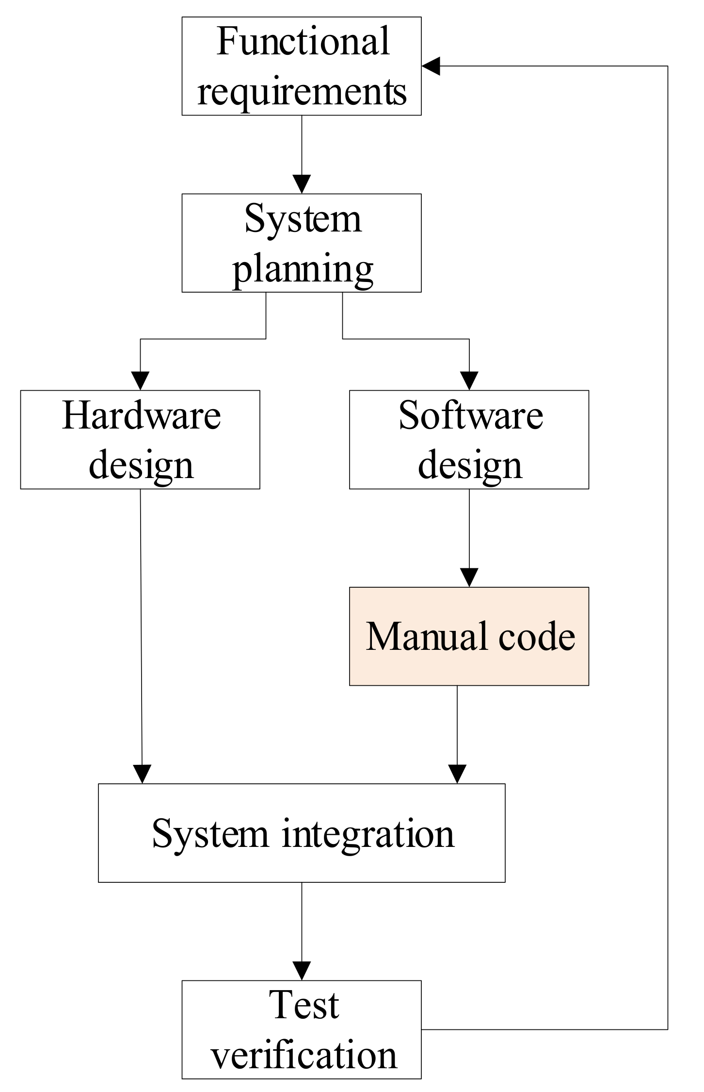
Indeed, faced with hundreds of thousands or even millions of lines of control code, traditional manual programming is time-consuming and laborious, as shown in Figure 1 [5,6]. It can no longer meet the development needs of modern products. With the rapid expansion of the amount of code, the defects of the traditional manual development model are very obvious. It is faced with many insurmountable difficulties, such as the forced extension of the product development cycle, the multiple R&D investments, and the difficulty of guaranteeing product reliability. It has been difficult to adapt to the current social requirements in product development and testing [1,5]. At present, the development speed of controllers in aerospace, automotives, etc., is becoming faster and faster. There are many defects in the traditional development process. For example, the errors introduced in the functional requirement analysis stage are generally found in the final testing stage, which causes the development process to be severely blocked or even pushed back.
2. Materials and Methods
2.1. Model-Based Design and Development Mode
To solve the problems faced by the traditional development process, MathWorks proposed a model-based design (MBD) method based on MATLAB software with the development of software design tools, as shown in Figure 2. The use of a unified software and hardware platform in the development process can unify the offline simulation of the control algorithm on the desktop, the control prototype test in the laboratory, and the actual test calibration process of the vehicles; thus, it can reduce the development cost and redundant work, and accelerate the development process. When this concept was proposed at the time, it was considered an invention in intelligent design and modeling, and it received the attention and application of researchers in industry and academia.
Compared with traditional design methods, the various processes of MBD are integrated and linked together. Developers can focus on the modeling of algorithms and test cases. Controller code can be automatically generated using Embedded CoderTM to reduce the manpower, material resources, and time required for manual programming, and it has been successfully applied to the development of large-scale projects. In addition, MATLAB is in a leading position in scientific computing and modeling. Many companies around the world have directly developed module libraries that support MBD in MATLAB, such as Texas Instruments, dSPACE, Quanser, TRlab, etc. MATLAB/Simulink is used as a tool to implement the processor-in-the-loop (PIL) experiments of DSP based on automatic code generation technology in this paper.
Different from the Model-in-the-Loop (MIL), Software-in-the-Loop (SIL), and Hardware-in-the-Loop (HIL) tests, the PIL test compiles the automatically generated code into the target system program, and then virtualizes the target hardware environment on the PC and performs the test [7,8,9]. It is one of the tests involved in a model-based approach that allows the combination of the computer simulation (computations performed on a computer) and the microprocessor simulation [10]. It is verified whether the function implemented by the code on the target processor (such as DSP) is consistent with the simulation model. The four test methods used in the controller development process, and their definitions, are shown in Table 1. Each test process has differences and connections, which together constitute a complete test process and a unified whole.
Research in this area has been extensive, and there are many studies reported in the world and particularly in Europe. A PIL simulation system was developed in [11], which has led to the full testing and validation of the GNC flight code to be ported to a VxWorks environment in a PowerPC8245 board, representative of the onboard computer, while a Field Programmable Gate Array (FPGA)-based PIL simulation test bench for the proposed machine was set up in [12]. Furthermore, [13] shows how to implement PIL and the preliminaries to HIL of electronic/electric systems with easy access technology through a code generation tool called Xilinx System Generator, an FPGA device, and a personal computer. By using the MBD, the embedded software is designed in [14], and the main interests are SIL and PIL approaches.
2.2. DSP Code Automatic Generation Based on MATLAB/Simulink
In the past, there was no connection between the model and the code. The simulation model was not directly related to the coding/code. The model was for intended theoretical analysis and algorithm design and could be used to guide programming. However, with the development of science and technology, the model and the code gradually merge, and the model and the code can be directly run jointly on the computer. Model and code are inseparable now, as shown in Figure 3.
The core technology in the MBD development method is automatic code generation technology. As an emerging engineering realization technology, automatic code generation technology has been widely used in aerospace and defense, automotive, industrial control, and automation fields [2,6,15]. Through advanced auxiliary design development tools, it is conducive to the rapid and efficient development of the controller.
The Embedded CoderTM product in the MATLAB product family integrates Texas Instruments Code Composer StudioTM, Analog DevicesTM VisualDSP++®, and other third-party embedded development environments, which can directly convert MATLAB/Simulink model block diagrams and Stateflow diagrams into efficient and optimized C/C++ program code, and the entire code generation, compilation, and corresponding target download process are all performed automatically. The automatically generated readable and compact C/C++ code can be conveniently used in embedded processors, target system rapid prototyping boards, and microprocessors used in mass production, so that control prototyping and product-level code can be completed rapidly.
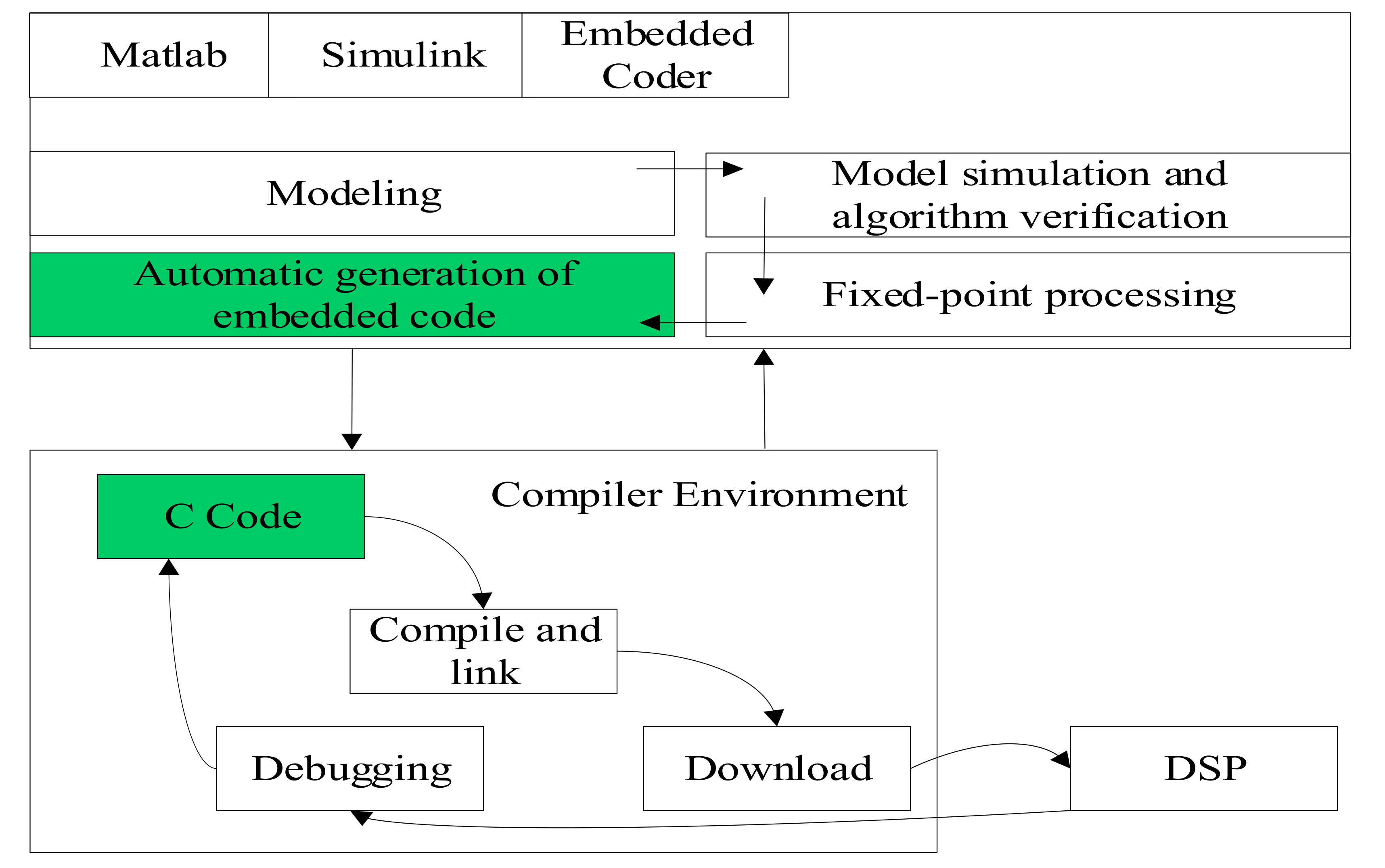
The first step is to build the PWM output control model in MATLAB/Simulink, which is the aforementioned MIL test, verify the algorithm through a purely mathematical simulation model, and then only keep the controller control algorithm part, after fixed-point processing (de-floating-point operation), to generate the embedded code that DSP can run. A flowchart of automatic code generation based on Embedded CoderTM in MATLAB/Simulink is shown in Figure 4 [16].
3. Results and Discussion
3.1. Experimental Platform
Pulse width modulation (PWM) is a technology that uses the digital output of a microprocessor to control analog circuits [16,17]. Motor output performance is closely related to its terminal voltage, and PWM technology is widely used in motor control technology. Through PWM technology, the electronic control unit can adjust the duty cycle according to the change in the external load to ensure the set speed of the motor [18,19].
The duty cycle is the ratio of the high level in a cycle. As shown in Figure 5a, the wave is a 10% PWM output, i.e., in the signal cycle, 10% of the time is on, and the remaining 90% of the time is off. Assuming that the power supply is 10 V and the duty cycle is 10%, it corresponds to an analog signal with an amplitude of 1 V. In Figure 5b,c, the PWM output with a duty cycle of 50% and 90% are shown, respectively. The three kinds of PWM output codes are three different analog signal values with the intensity of 10%, 50%, and 90% of the full-scale value. This is a simple PWM with equal pulse width, and the realized adjustment voltage is also a fixed value.
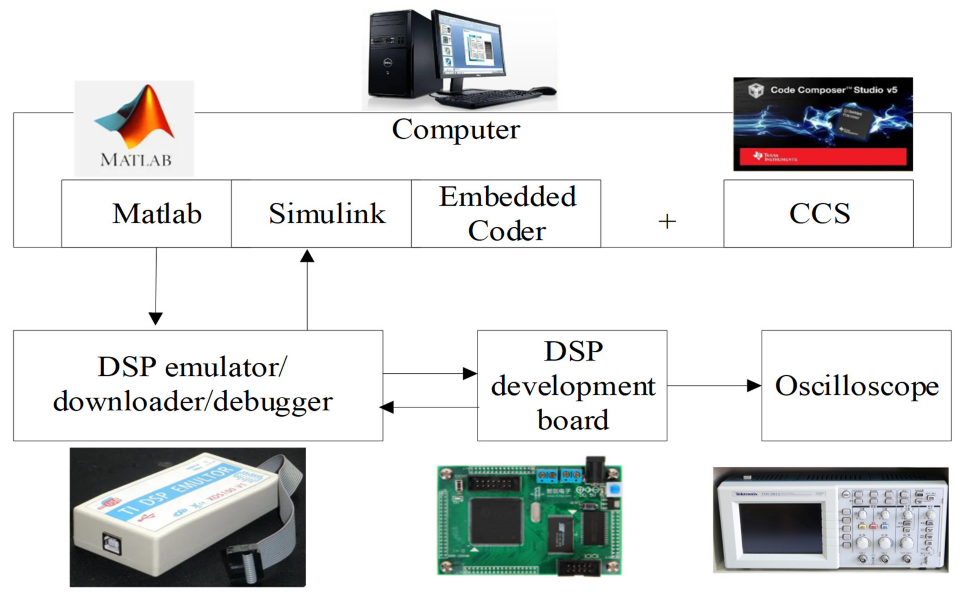
The composition and schematic diagram of the experimental software and hardware platform is shown in Figure 6, in which the hardware mainly includes the computer, a DSP development board, a DSP emulator/downloader/debugger, and an oscilloscope, while the software mainly includes MATLAB/SimulinkTM and Texas Instruments’ Code Composer StudioTM.
The DSP controller can generate six PWM signals. In the verified MATLAB model, only the control modules that need to be processed in the DSP are retained, and the pulse code modulation PWM module in Texas Instruments’ Code Composer StudioTM is substituted for the modules in the original simulation model, and then the model is fixed-pointed to meet the low power requirements of the TMS320F2812 DSP chip, because the fixed-point signal calculation is simple and the calculation speed is fast, and the calculation time is reduced. In addition, it should be pointed out that TMS320F28335 DSP has been widely used to replace the original DSP2812. DSP28335 is a 32-bit floating-point DSP controller newly launched by TI. Compared with fixed-point DSP2812, DSP28335 adds a single-precision floating-point arithmetic unit (FPU) and high-precision PWM, doubles Flash (256 K × 16 Bit), and adds a direct memory access (DMA) function, which can directly store ADC conversion results in any storage space of DSP [20,21].
The Embedded CoderTM tool is used to automatically generate the C language project file for the TI CCS compiler, further complete the compilation, connection, and download, and finally run on the DSP development board to complete the PIL real-time tests.
3.2. Experimental Results
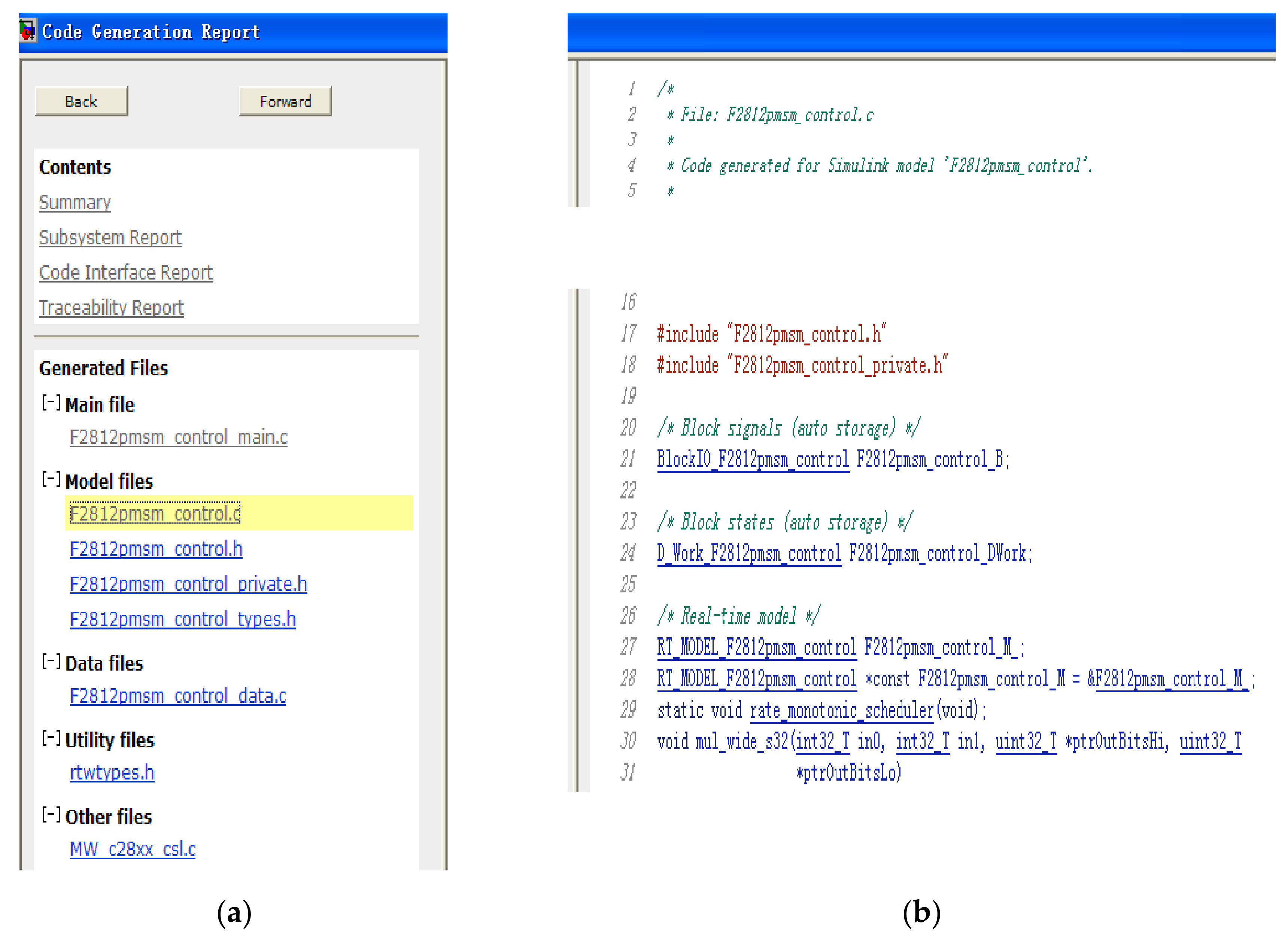
Through MATLAB Embedded CoderTM automatic compilation, we can obtain the required C code files. Through the code generation report, we can see that the generated report includes a summary, subsystem report, a code interface report, traceability report, etc., as shown in Figure 7. The generated files mainly include main files, model files (including C-language header file .h files, C-language source files .c files, etc.), utility files, and other files.
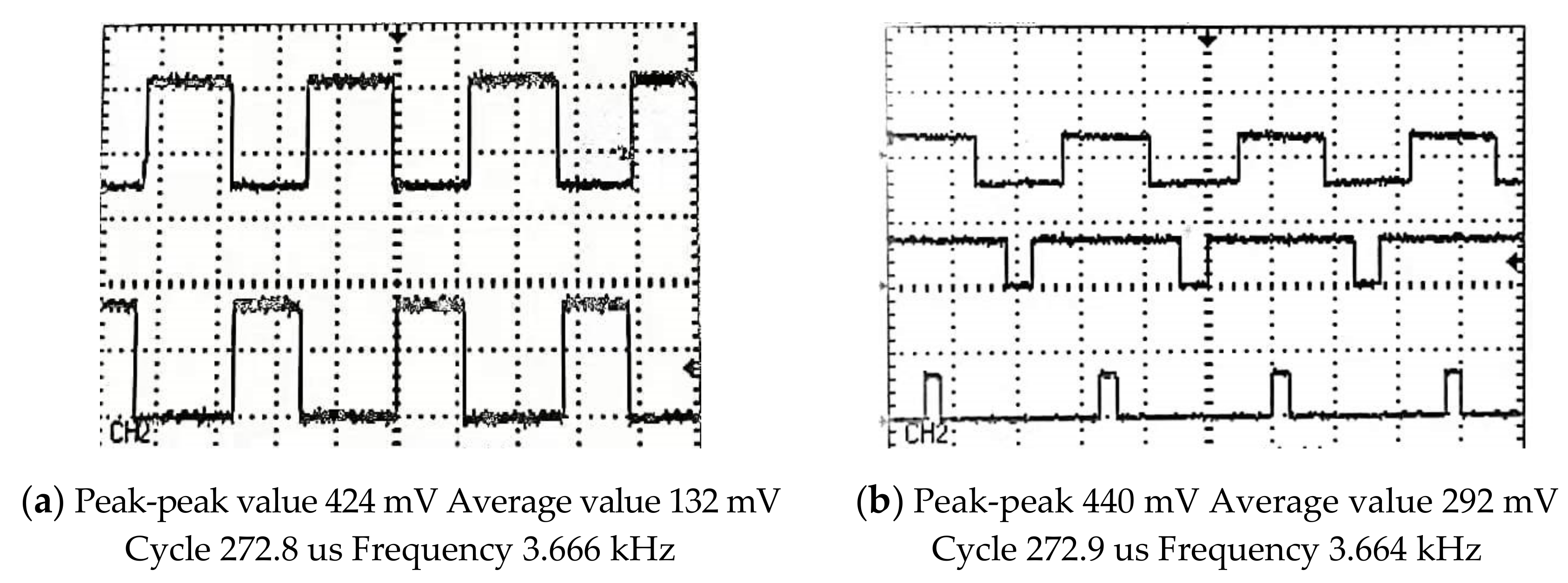
There are three elements for evaluating high-quality code: readability, maintainability, and changeability. As shown in Figure 7, we can see that the MATLAB Embedded CoderTM can generate independent, readable, and portable C/C++ code from the MATLAB/Simulink model. Although the default variable data type of the automatically generated code is a structure, a large number of structure types are used in the program, which is laborious to read. However, we can manually improve the readability of the code later. In terms of the overall development process, model-based design can still speed up project development and reduce research and development costs. After the automatically generated code runs on the DSP, we can judge whether the program is correct by observing the waveform of the DSP output pin through the oscilloscope. Under different duty cycle, the PWM output waveform is shown in Figure 8.
4. Conclusions
As former President Jack Little of MathWorks stated, in the process of embedded software development, model-based design can bring us at least four benefits. The graphical design is clear and easy to communicate and maintain. There are more efficient early verification methods. The code can be generated automatically. The relevant information in the model can be read through the software, and documents can be automatically created to realize document automation.
As shown by the example of DSP controller PWM output control shown in this paper, engineers only need to build the control model and verify the correctness of the model in MATLAB/Simulink from the perspective of the entire development and design process, without writing any code, to obtain reliable and accurate embedded code. Researchers no longer need to possess the complex C language editing knowledge, and can realize the comparison between different control methods and improved methods more quickly.
Author Contributions
Conceptualization, Q.Z.; methodology, Q.Z.; software, Q.Z.; validation, Q.Z.; formal analysis, Q.Z.; investigation, Q.Z.; resources, Q.Z.; data curation, Q.Z.; writing—original draft preparation, Q.Z.; writing—review and editing, Q.Z. and W.P.; visualization, Q.Z.; supervision, Q.Z. and W.P.; project administration, Q.Z. and W.P.; funding acquisition, Q.Z. and W.P. All authors have read and agreed to the published version of the manuscript.
Funding
This research was funded by the Shandong Provincial Natural Science Foundation, grant number ZR2020QF059; Projects of Shandong Province Higher Educational Science and Technology Program, grant number J18KA348; Foundation of State Key Laboratory of Automotive Simulation and Control, grant number 20181119; Shandong University Laboratory Research Project, grant number sy20213303, and Shandong University Laboratory Software Project, grant number sy2016408. The APC was funded by ZR2020QF059.
Data Availability Statement
The data in the paper can be requested by email to the corresponding author.
Acknowledgments
Thanks to the reviewers and editors for their guidance and hard work on this paper, which helped to make the structure of the paper clearer and the content smoother. We are grateful for the technical support from MATLAB/Simulink software and the user manual provided by MathWorks. In addition, we acknowledge the support of the Shandong Provincial Natural Science Foundation, grant number ZR2020QF059; Foundation of State Key Laboratory of Automotive Simulation and Control, grant number 20181119; Shandong University Laboratory Research Project, grant number sy20213303, and Shandong University Laboratory Software Project, grant number sy2016408. The APC was funded by ZR2020QF059.
Conflicts of Interest
The authors declare no conflict of interest.
Abbreviations
| AI | artificial intelligence |
| DMA | direct memory access |
| DSP | digital signal processing |
| FPGA | Field Programmable Gate Array |
| FPU | floating-point unit |
| HIL | hardware-in-the-loop |
| MBD | model-based design |
| MIL | model-in-the-loop |
| OTA | over-the-air technology |
| PIL | processer-in-the-loop |
| PWM | pulse width modulation |
| SIL | software-in-the-loop |
References
- Qi, Z. Motor Controller Design Using dSPACE and Based on V-Mode Development. Res. Explor. Lab. 2014, 33, 141–144. [Google Scholar]
- Qi, Z.; Xiaoling, F.; Guojing, X. Implementation of a Rapid Prototyping Controller for asynchronous Motor. In Proceedings of the Chinese Automation Congress, Beijing, China, 22–24 October 2021. [Google Scholar]
- Shanghai Three Drivers Culture Media Co., Ltd. Where Is the Sale of Cars, Obviously It Is the Sale of Software, What Are the Models with 100 Million Lines of Software Code Written? 19 August 2020. Available online: http://k.sina.com.cn/article_6347788417_17a5b908100100pwm0.html (accessed on 2 January 2022).
- Jia, R. It May Introduce 4–6 Security Flaws per Thousand Lines of Code in Smart Vehicles. 27 May 2021. Available online: https://auto.sina.com.cn/news/2021-05-27/detail-ikmxzfmm5018318.shtml (accessed on 2 January 2022).
- Jie, L. Model-Based Design and Embedded Implementation; Beihang University Press: Beijing, China, 2010. [Google Scholar]
- Jie, L.; Gongyu, W.; Yubo, Z. Model-Based Design for MCU; Beihang University Press: Beijing, China, 2011. [Google Scholar]
- Tulpule, P.; Rezaeian, A.; Karumanchi, A.; Midlam-Mohler, S. Model Based Design (MBD) and Hardware In the Loop (HIL) validation: Curriculum development. In Proceedings of the American Control Conference, Seattle, WA, USA, 24–26 May 2017; pp. 5361–5366. [Google Scholar] [CrossRef]
- Xiangzhong, Y.; Jinwen, A.; Wenge, C. The Research on Application of Embedded Auto Code Generation. J. Proj. Rocket. Missiles Guid. 2008, 28, 250–257. [Google Scholar]
- Baxter, M. Task-processor mapping for real-time parallel systems using genetic algorithms with hardware-in-the-loop. In Proceedings of the First International Conference on Genetic Algorithms in Engineering Systems: Innovations and Applications, Sheffield, UK, 12–14 September 1995; pp. 158–163. [Google Scholar] [CrossRef]
- Kuznyetsov, O. Understanding the Basics of the Model-Based Techniques for Control Engineers with Simulink and BeagleBone Black: Processor-in-the-Loop Simulation of a DC Motor Speed Control. In Proceedings of the XIth International Scientific and Practical Conference on Electronics and Information Technologies (ELIT), Lviv, Ukraine, 16–18 September 2019; pp. 67–71. [Google Scholar] [CrossRef]
- Hu, M.; Zeng, G.; Yao, H.; Tang, Y. Processor-in-the-loop demonstration of coordination control algorithms for distributed spacecraft. In Proceedings of the 2010 IEEE International Conference on Information and Automation, Harbin, China, 20–23 June 2010; pp. 1008–1011. [Google Scholar] [CrossRef]
- Ruba, M.; Hunor, N.; Hedesiu, H.; Martis, C. FPGA based processor in the loop analysis of variable reluctance machine with speed control. In Proceedings of the IEEE International Conference on Automation, Quality and Testing, Robotics (AQTR), Los Angeles, CA, USA, 23–25 January 2016; pp. 1–6. [Google Scholar] [CrossRef]
- Mina, J.; Flores, Z.; Lopez, E.; Perez, A.; Calleja, J.-H. Processor-in-the-loop and hardware-in-the-loop simulation of electric systems based in FPGA. In Proceedings of the 13th International Conference on Power Electronics (CIEP), Chengdu, China, 24–27 October 2016; pp. 172–177. [Google Scholar] [CrossRef]
- Galarza, J. Software and Processor-in-the-Loop Execution for a Grid Connected Modular Multi-Level Converter. In Proceedings of the 2019 IEEE XXVI International Conference on Electronics, Electrical Engineering and Computing (INTERCON), Lima, Peru, 12–14 August 2019; pp. 1–4. [Google Scholar] [CrossRef]
- Liu, J.; Zhou, Y. Model-Based Design for DSP; National Defense Industry Press: Beijing, China, 2011. [Google Scholar]
- Lugang, W. PWM Inverter Based on New Space Vector Selection Model. Electr. Mach. Control Appl. 2001, 28, 27–30. [Google Scholar]
- Hu, H.; Yao, W.; Lu, Z. Design and Implementation of Three-Level Space Vector PWM IP Core for FPGAs. IEEE Trans. Power Electron. 2007, 22, 2234–2244. [Google Scholar] [CrossRef]
- Liu, X.; Zhang, Q. Robust Current Predictive Control-Based Equivalent Input Disturbance Approach for PMSM Drive. Electronics 2019, 8, 1034. [Google Scholar] [CrossRef] [Green Version]
- Zhao, Y.; Liu, X.; Zhang, Q. Predictive Speed-Control Algorithm Based on a Novel Extended-State Observer for PMSM Drives. Appl. Sci. 2019, 9, 2575. [Google Scholar] [CrossRef] [Green Version]
- Chen, P.; Zheng, J. PMLSM Servo System Design and Implement Based on DSP28335. Modul. Mach. Tool Autom. Manuf. Tech. 2013, 1, 80–83. [Google Scholar]
- Wei, T.; Renze, L.; Wengang, G.; Huiqi, Z. Design of DSP Minimum System Based on TMS320F28335. Ind. Control Comput. 2012, 4, 98–99. [Google Scholar]
Figure 1.
The traditional development model.

Figure 2.
The model-based design.

Figure 3.
Model and code from independence to integration.

Figure 4.
The embedded code automatic generation process of DSP.

Figure 5.
The technology of PWM. (a) the duty cycle is 10%; (b) the duty cycle is 50%; (c) the duty cycle is 90%.
Figure 5.
The technology of PWM. (a) the duty cycle is 10%; (b) the duty cycle is 50%; (c) the duty cycle is 90%.

Figure 6.
The composition and schematic diagram of the experimental software and hardware platform.

Figure 7.
Code generation report and its generated files. (a) code generation report; (b) generated C file.
Figure 7.
Code generation report and its generated files. (a) code generation report; (b) generated C file.

Figure 8.
Observation of the PWM output waveform with an oscilloscope. (a) PWM waveform output on the pins of the DSP chip; (b) in different duty cycles.
Figure 8.
Observation of the PWM output waveform with an oscilloscope. (a) PWM waveform output on the pins of the DSP chip; (b) in different duty cycles.


Table 1.
The four test methods and their definitions.
| Abbreviation | Full Name | Meaning of Definition |
|---|---|---|
| MIL | Model-in-the-Loop | In the Simulink model, the control algorithm model and the controlled object model are connected to form a closed loop for simulation (a purely mathematical model). |
| SIL | Software-in-the-Loop | To verify that the automatically generated code and the original model used for code generation are consistent in function and behavior (a mathematical model and code). |
| PIL | Processer-In-the-Loop | The code generated runs on the actual controller in the PIL tests, so, in addition to verifying whether the code and the model are consistent, the longest running time of the algorithm on the actual controller can also be obtained (a mathematical model and actual controller). |
| HIL | Hardware-in-the-Loop | Different from PIL, HIL is used to test the controller system. The control system includes hardware, low-level software, and application-level software (real controller system and virtual real object). |
Publisher’s Note: MDPI stays neutral with regard to jurisdictional claims in published maps and institutional affiliations. |
© 2022 by the authors. Licensee MDPI, Basel, Switzerland. This article is an open access article distributed under the terms and conditions of the Creative Commons Attribution (CC BY) license (https://creativecommons.org/licenses/by/4.0/).
Share and Cite
MDPI and ACS Style
Zhang, Q.; Pei, W. DSP Processer-in-the-Loop Tests Based on Automatic Code Generation. Inventions 2022, 7, 12. https://doi.org/10.3390/inventions7010012
AMA Style
Zhang Q, Pei W. DSP Processer-in-the-Loop Tests Based on Automatic Code Generation. Inventions. 2022; 7(1):12. https://doi.org/10.3390/inventions7010012
Chicago/Turabian StyleZhang, Qi, and Wenhui Pei. 2022. "DSP Processer-in-the-Loop Tests Based on Automatic Code Generation" Inventions 7, no. 1: 12. https://doi.org/10.3390/inventions7010012