
Thermal Performance Improvement by Rotating Thermosyphon Loop in Rotor of an Interior Permanent Magnet Synchronous Electric Motor


Abstract
:1. Introduction
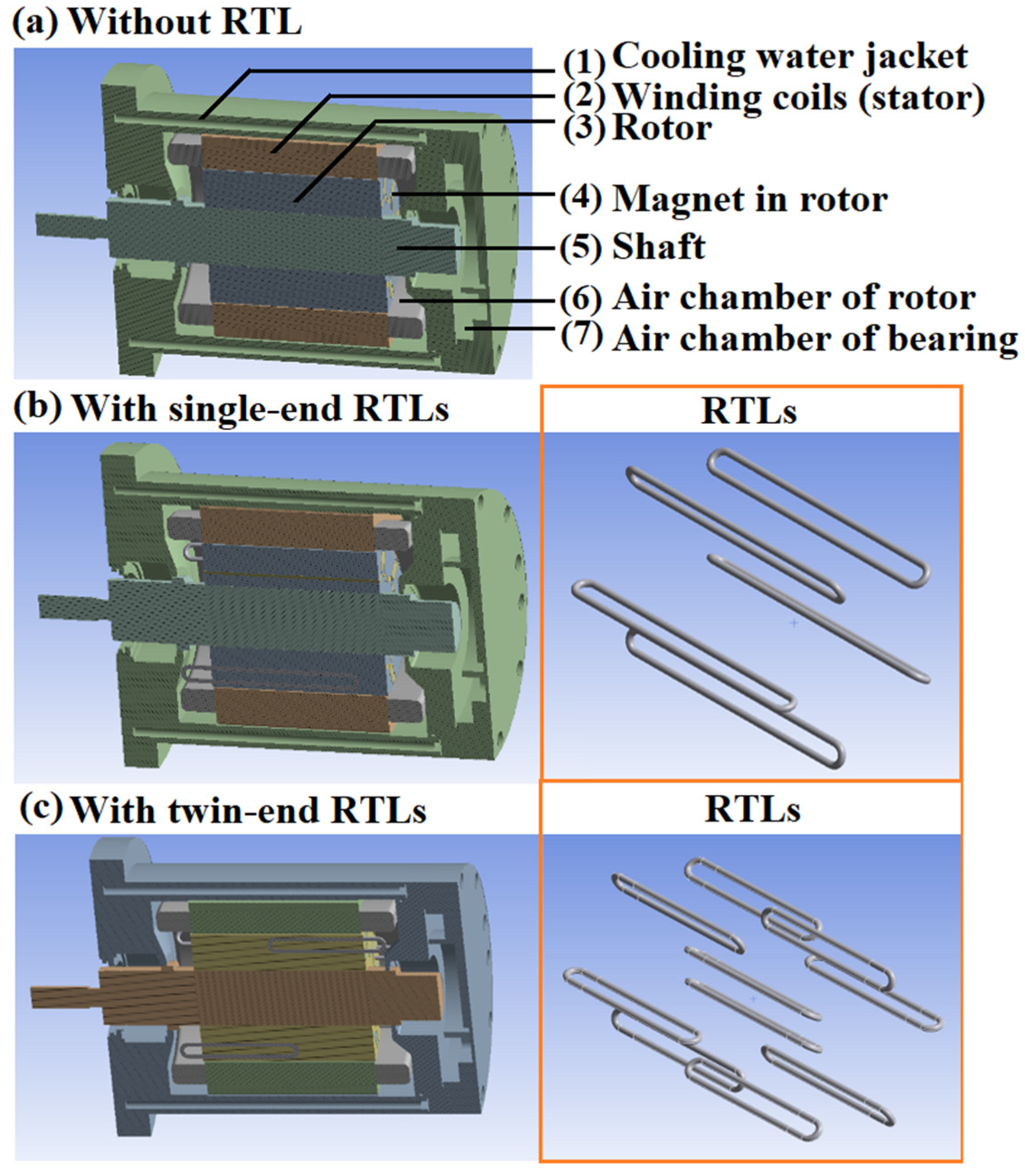
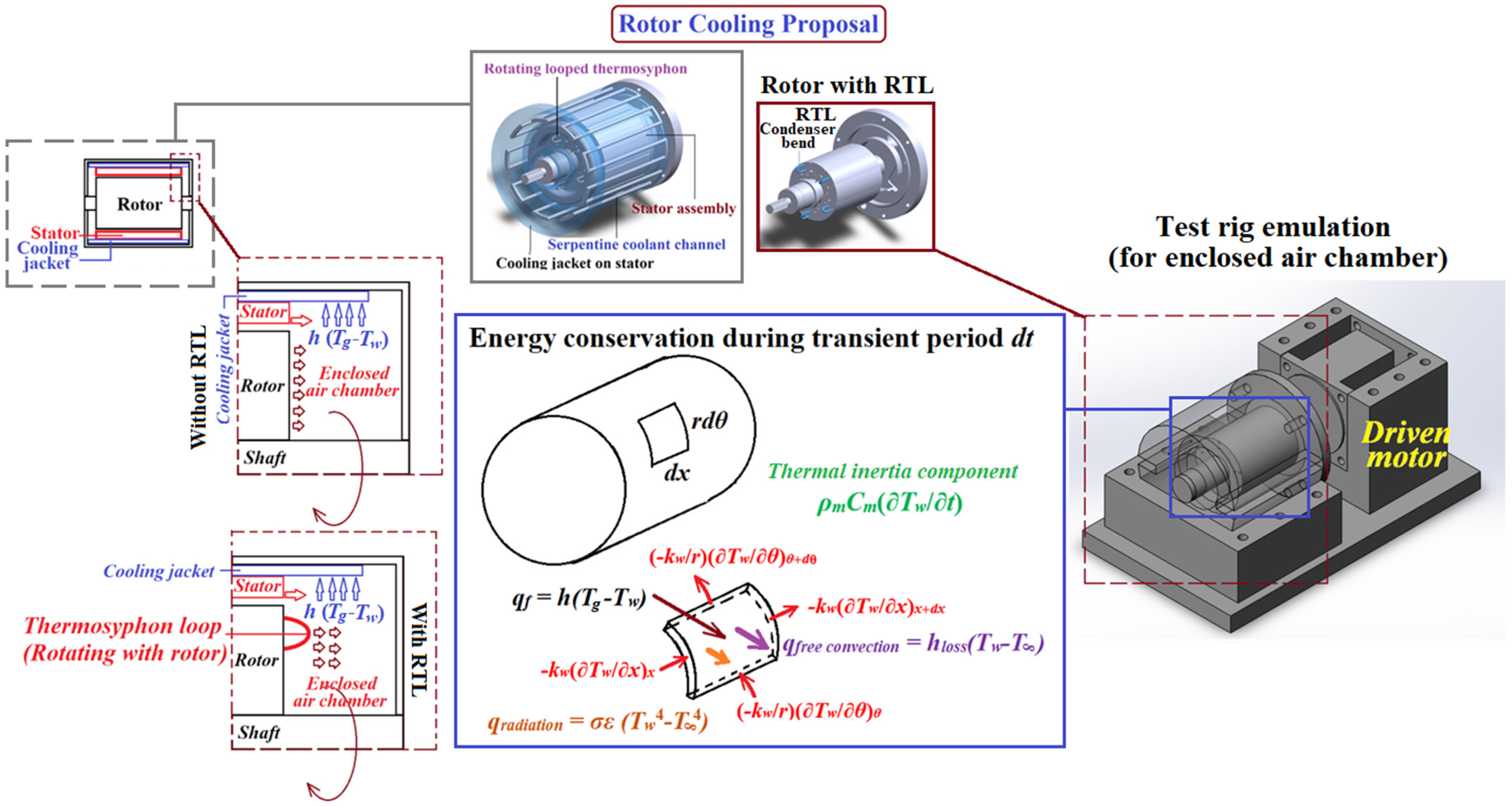
2. Methods
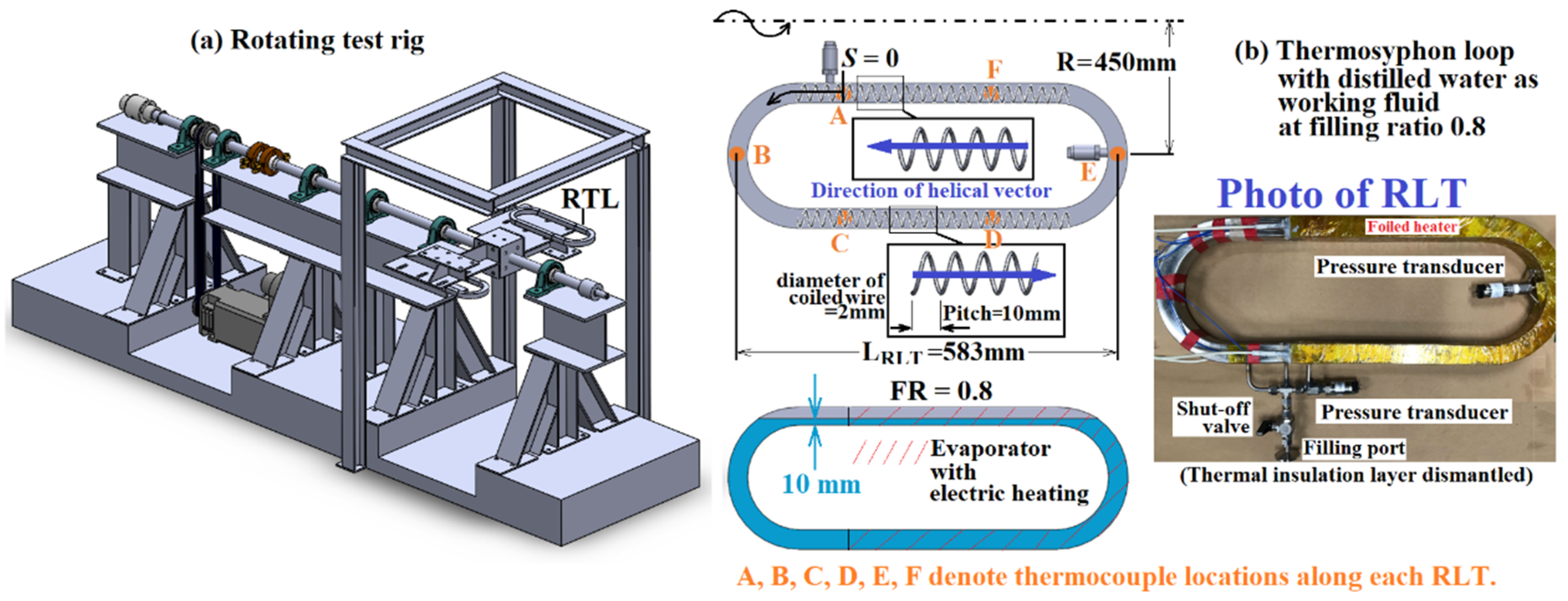
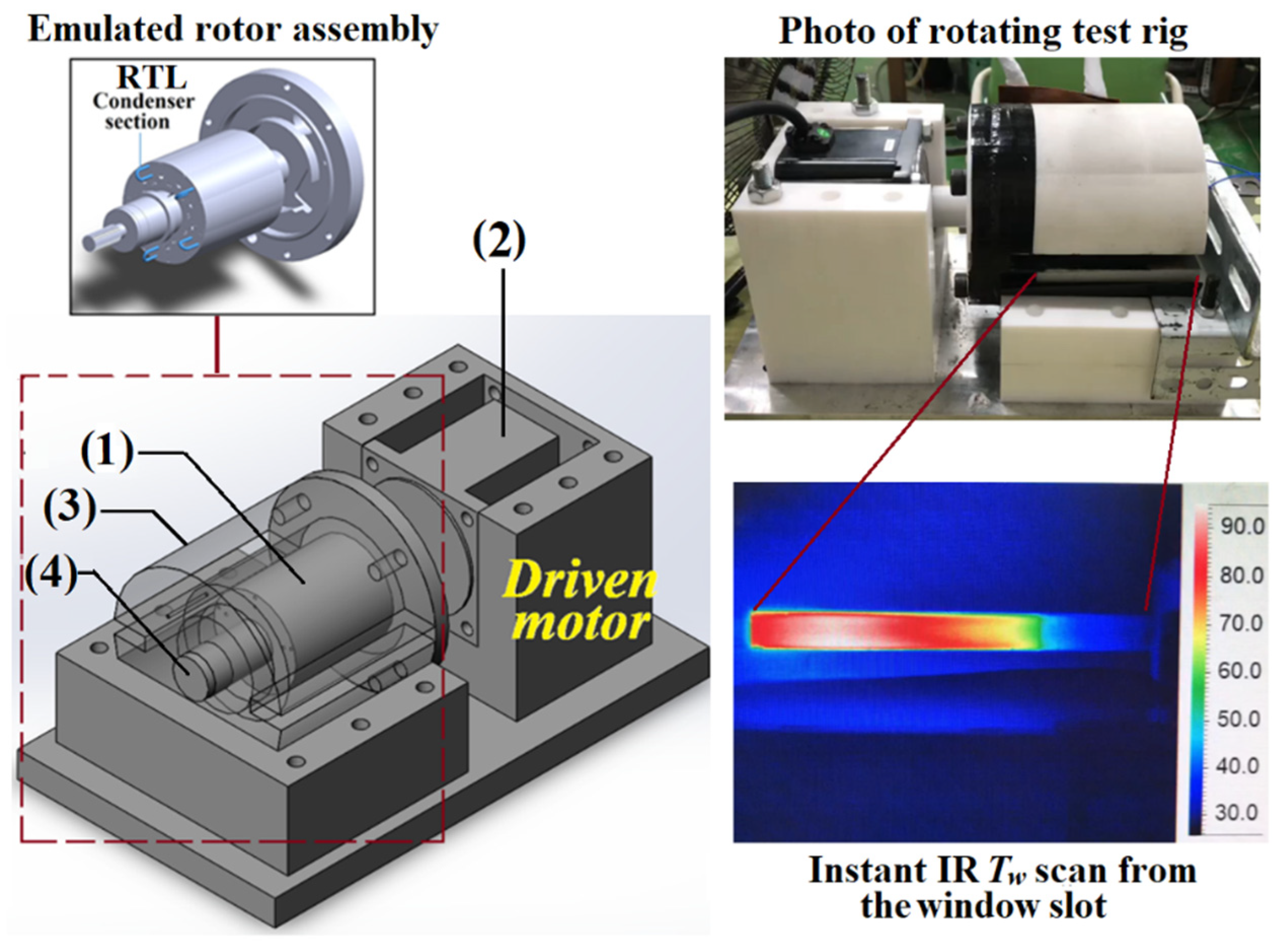
2.1. Experimental Method
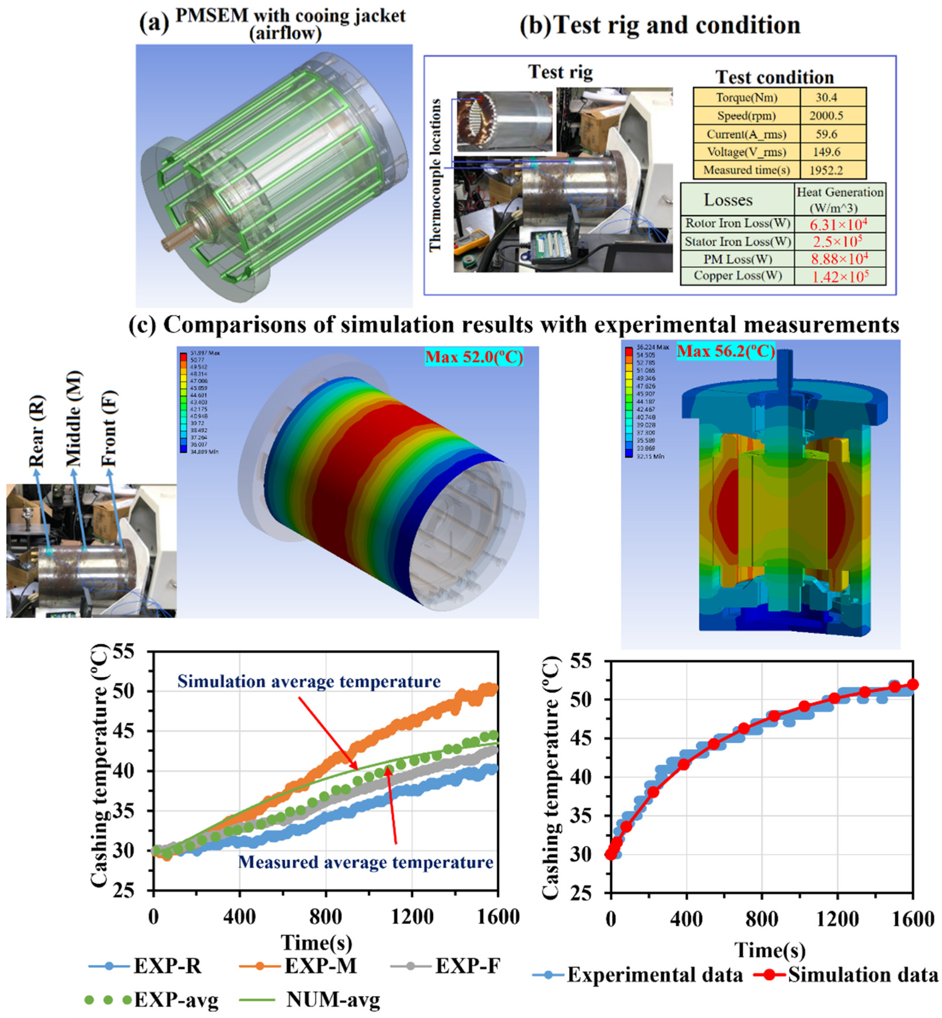
2.1.1. Steady State Thermocouple Method
2.1.2. Transient Thermography Method
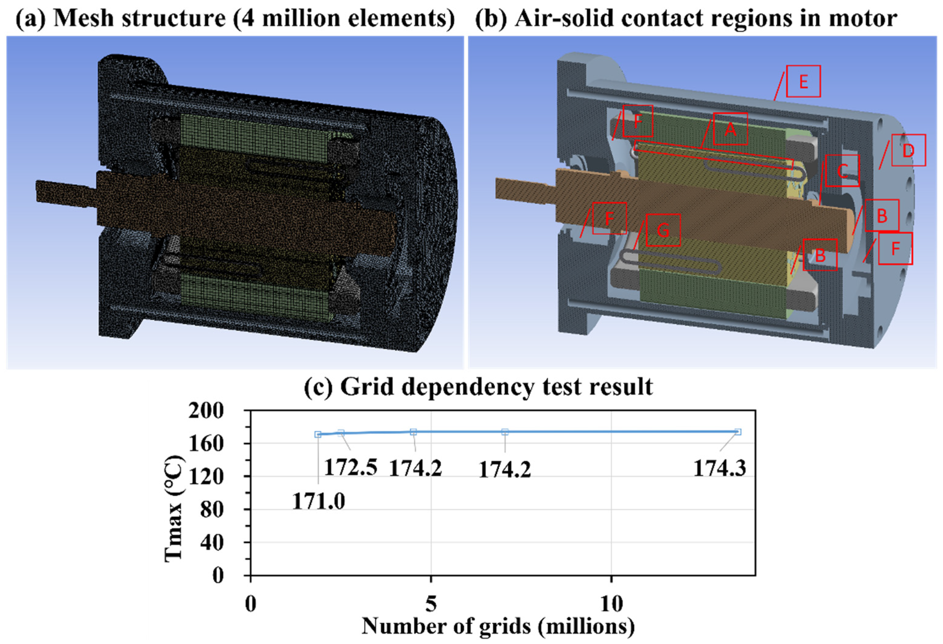
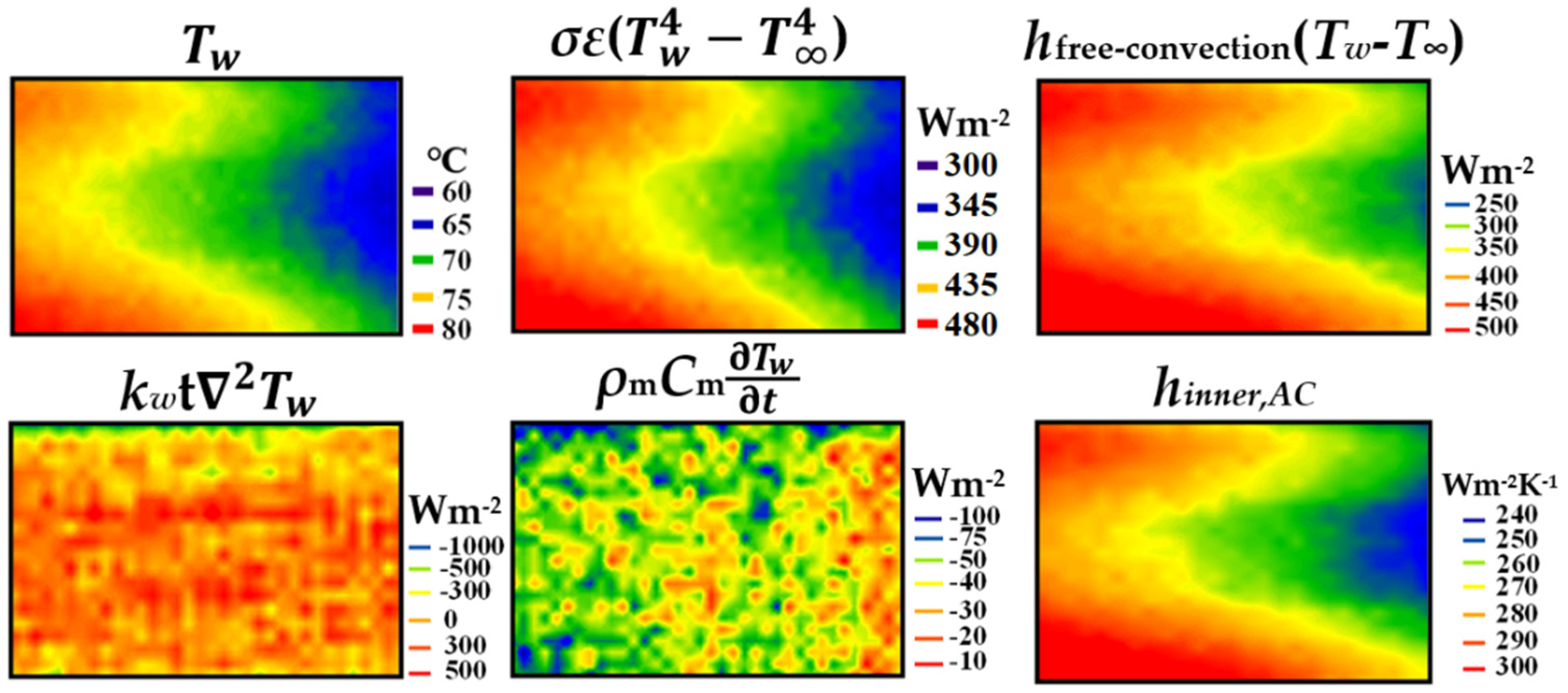
2.2. Numerical Method
3. Results and Discussion
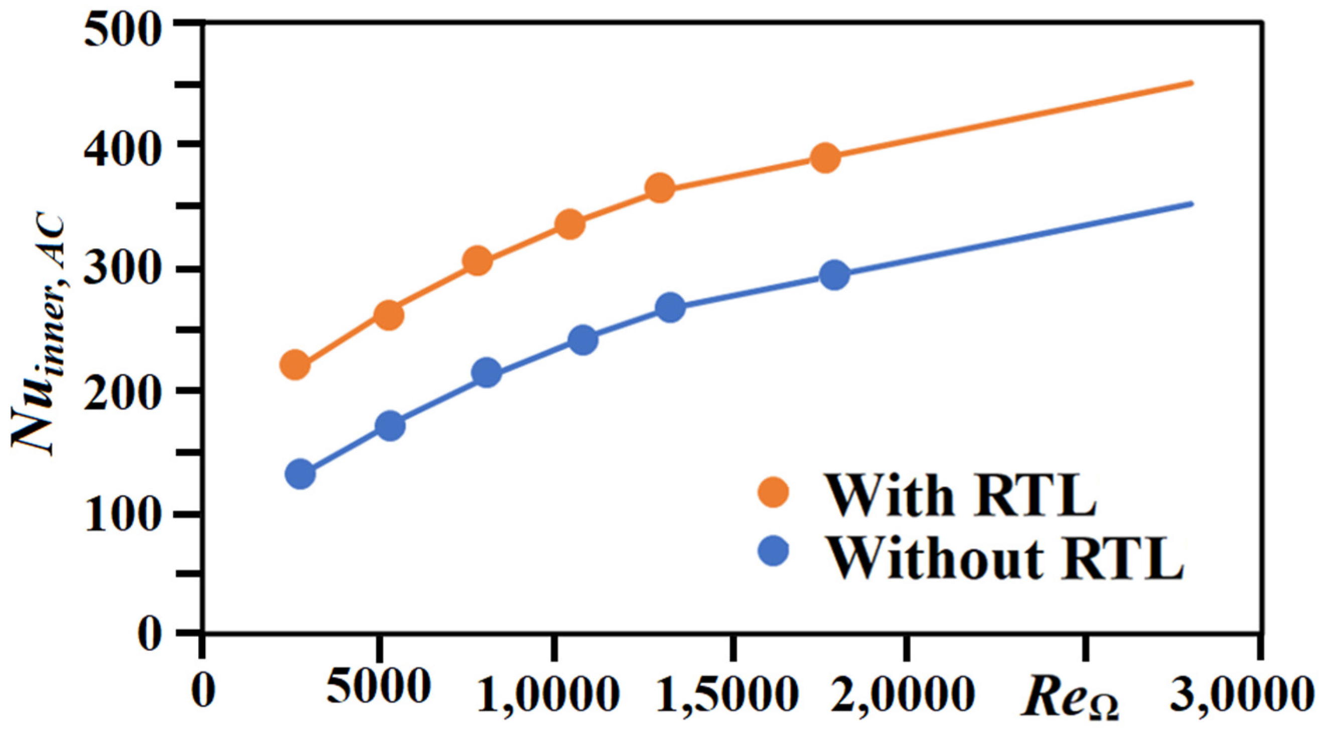
3.1. Experimental Results
3.2. Numerical Results
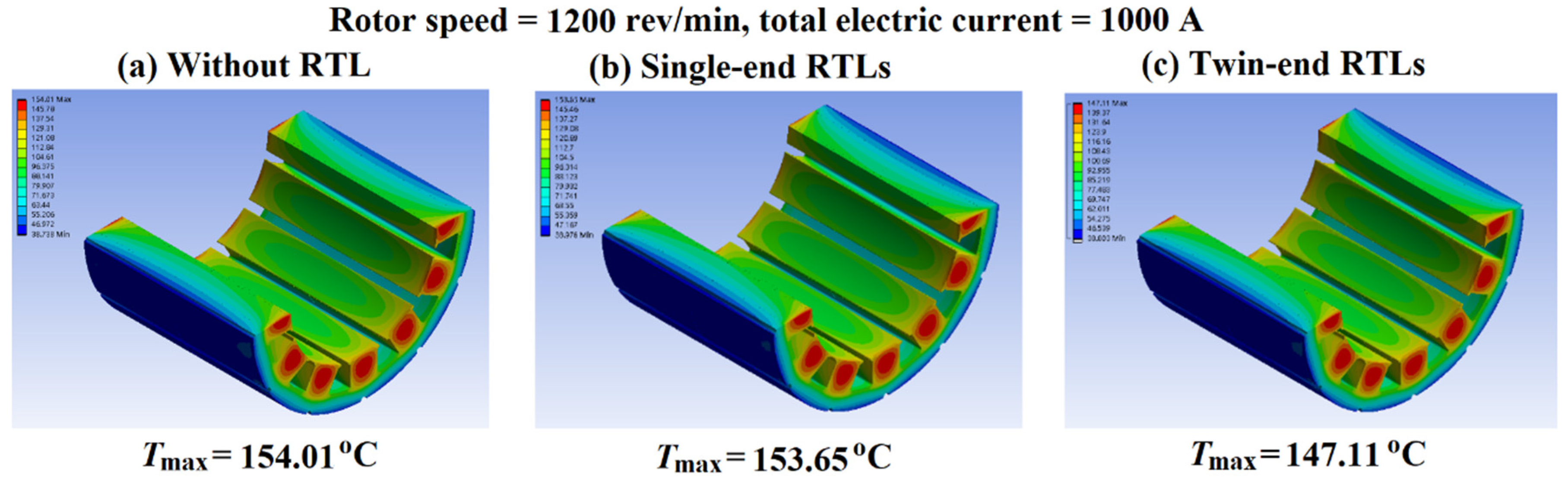
3.2.1. Baseline Condition
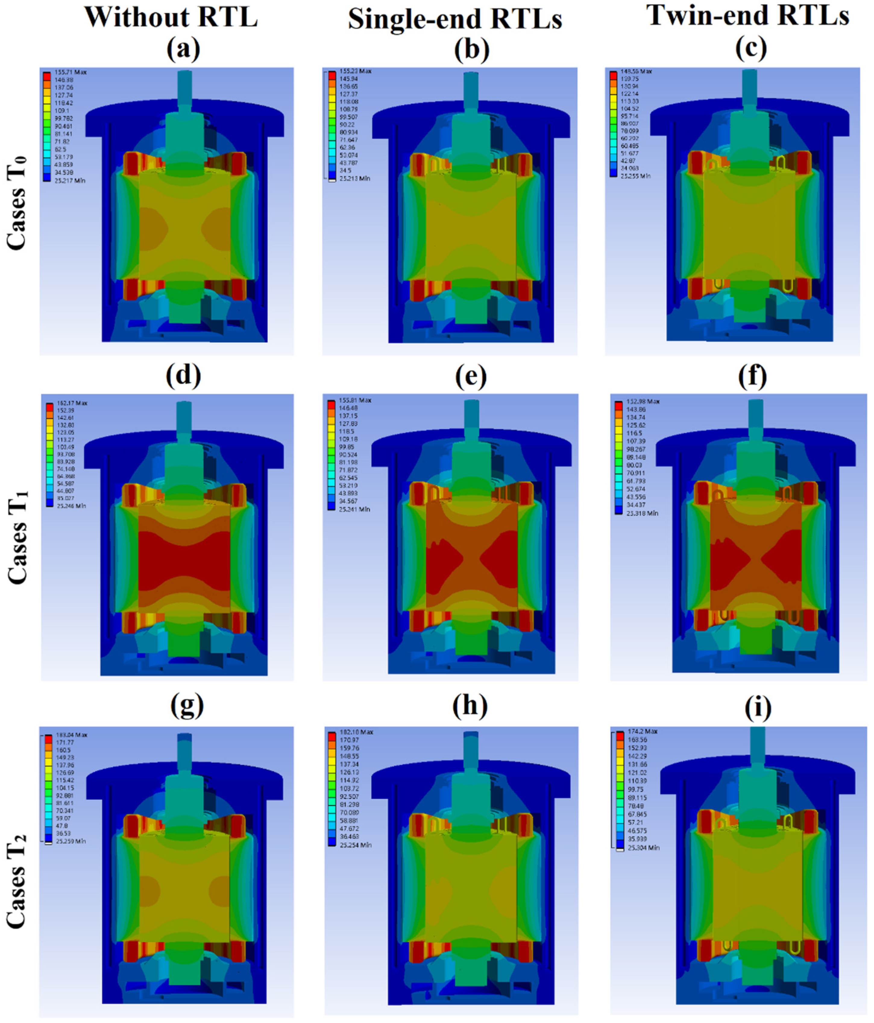
3.2.2. T0–T2 Operating Conditions
4. Conclusions
- 1.
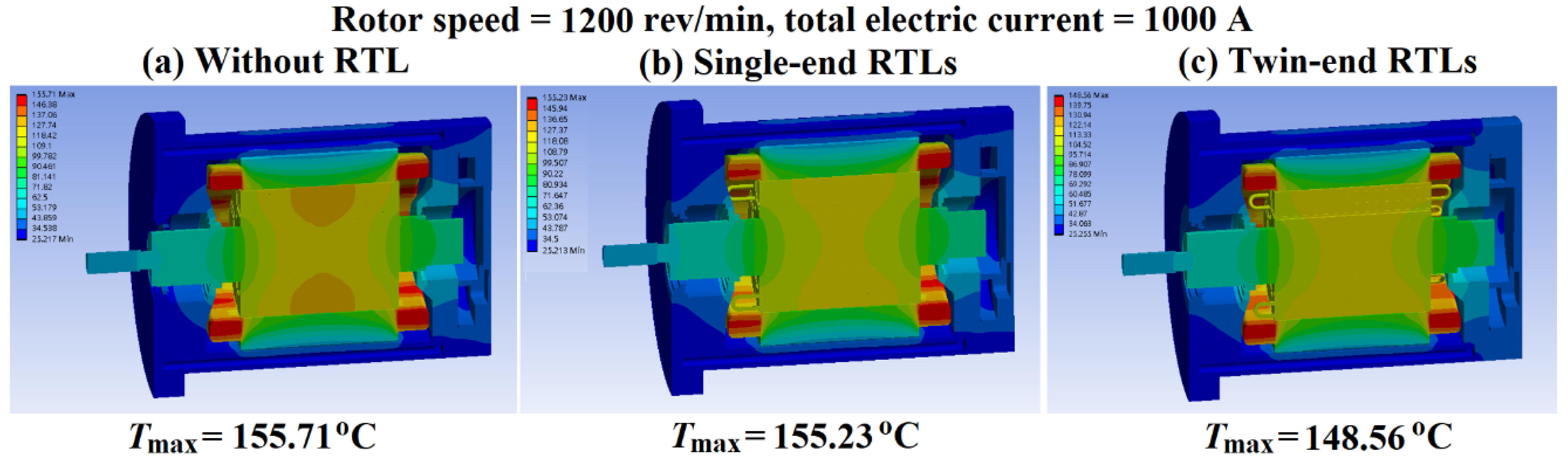
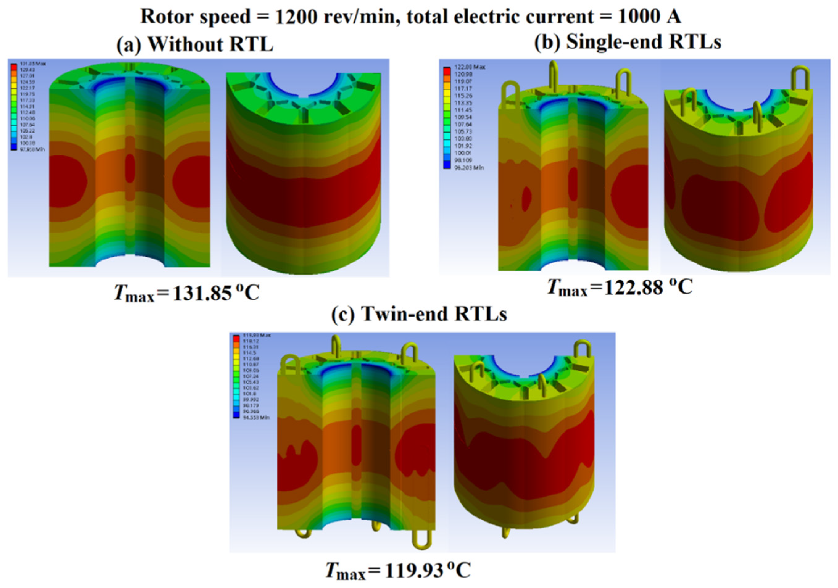
- The effective axial heat-transfer pathway constructed by the RTL in the rotor acts synergistically with its stirring effect, which augments the convective heat-transfer in the air chamber to considerably reduce the temperatures in the rotating components with moderate temperature reductions in the coiled windings of the stator and Tmax in the motor at T0–T2 operating conditions. At the rotor speeds and total electrical currents in the ranges of 1200–1500 rev/min and 1000–1200 A, the Tmax values in the rotors with the single- and twin-end RTLs are reduced 8–14 °C and 10–22 °C, respectively, from those without RTL.
- 2.
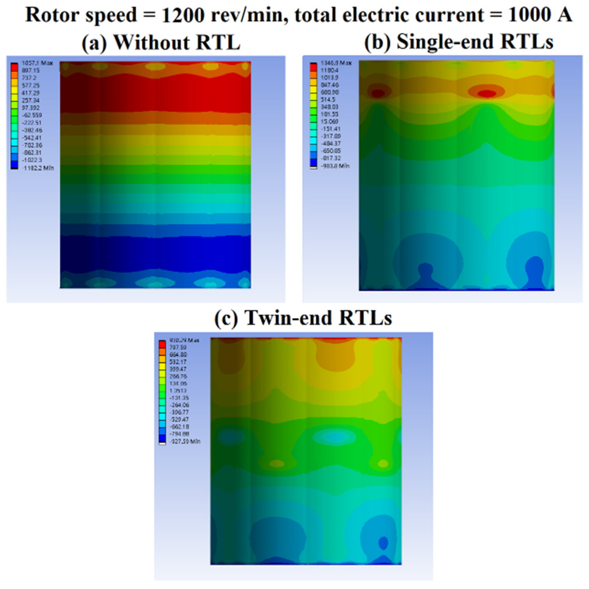
- The effective thermal conductivity (keff) and the average convective heat-transfer coefficient on the rotating surface of the condenser bend (hext.con) for the RTL, as well as the heat-transfer rate on the annular surface of the front/rear air chamber with and without the RTLs increase with rotor speed. The higher degrees of thermal performance improvements attributed to the twin-end RTLs in the rotor emerge when the various losses in the PMSEM are increased by raising the rotor speed instead of adding the motor input power at a fixed rotor speed.
- 3.
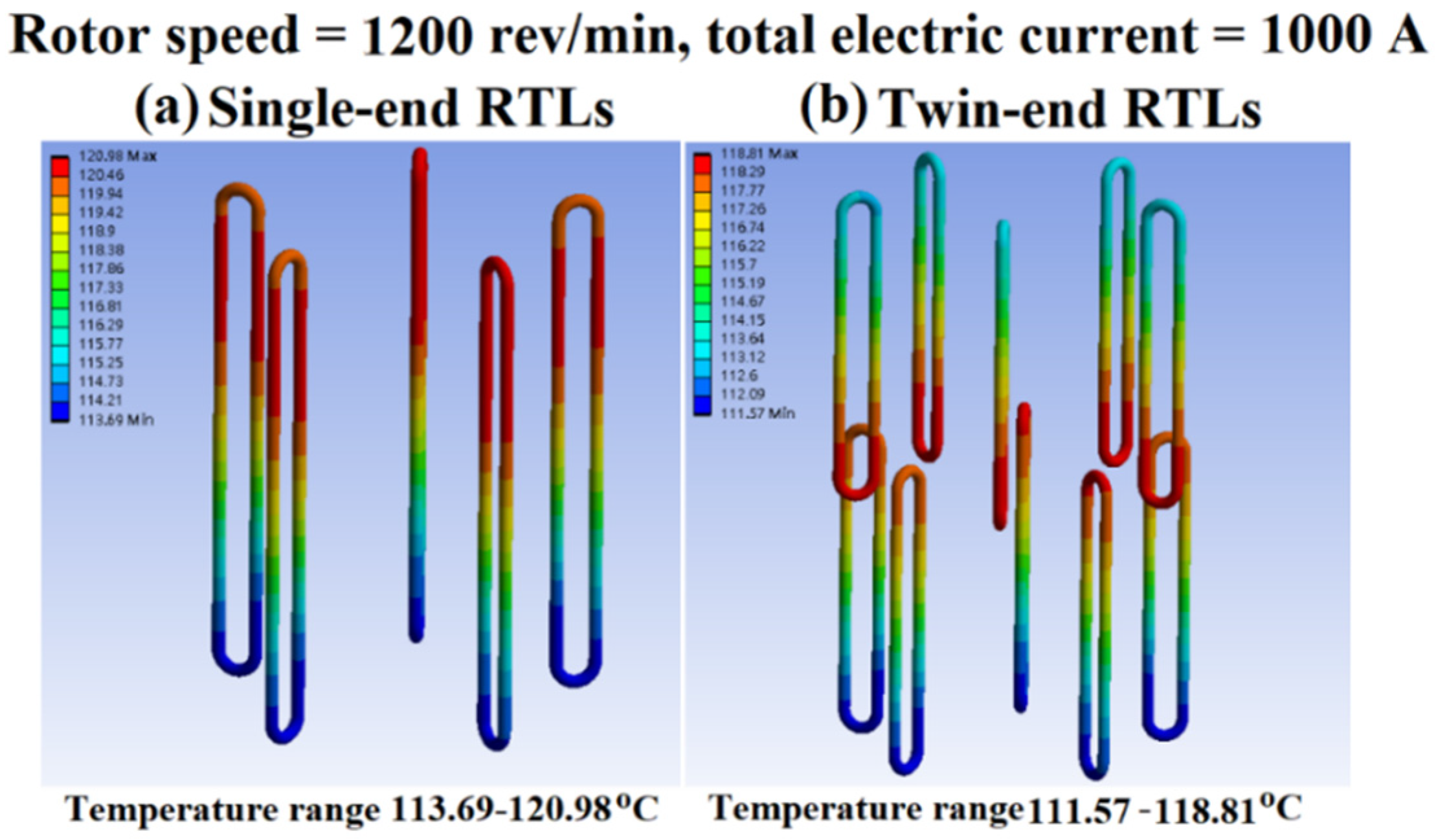
- The in-rotor twin-end RTLs considerably promote the axial heat flux transmission, leading to reduced axial temperature gradients of the rotating components from those without RTL. The combined reductions in temperatures and axial temperature gradients of the rotating assemblies by implanting the RTLs in a rotor permit the intensification of the magnetic flux of rotor with its temperatures at sustainable levels to assist in resolving the thermal barrier that hinders the further increase in power density of an electric motor.
Author Contributions
Funding
Institutional Review Board Statement
Informed Consent Statement
Data Availability Statement
Acknowledgments
Conflicts of Interest
References
- Sebastian, T. Temperature effects on torque production and efficiency of PM motors using NdFeB magnets. IEEE Trans. Ind. Appl. 1995, 31, 353–357. [Google Scholar] [CrossRef]
- Mecrow, B.C.; Jack, A.G. Efficiency trends in electric machines and drives. Energy Policy 2008, 36, 4336–4341. [Google Scholar] [CrossRef]
- Saidur, R. A review on electrical motors energy use and energy savings. Renew. Sustain. Energy Rev. 2010, 3, 877–898. [Google Scholar] [CrossRef]
- Caricchi, F.; Crescimbini, F.; Honorati, O. Modular axial-flux permanent-magnet motor for ship propulsion drives. IEEE Trans. Energy Convers. 1999, 14, 673–679. [Google Scholar] [CrossRef]
- Scowby, S.T.; Dobson, R.T.; Kamper, M.J. Thermal modelling of an axial flux permanent magnet machine. Appl. Therm. Eng. 2004, 24, 193–207. [Google Scholar] [CrossRef]
- Liu, R.; Zheng, P.; Xie, D.; Wang, L. Research on the high power density electromagnetic propeller. IEEE Trans. Magn. 2007, 43, 355–358. [Google Scholar] [CrossRef]
- Ye, L.; Li, D.; Ma, Y.; Jiao, B. Design and performance of a water-cooled permanent magnet retarder for heavy vehicles. IEEE Trans. Energy Convers. 2011, 26, 953–958. [Google Scholar] [CrossRef]
- Mezani, S.; Takorabet, N.; Laporte, B. A combined electromagnetic and thermal analysis of induction motors. IEEE Trans. Magn. 2005, 41, 1572–1575. [Google Scholar] [CrossRef]
- Alexandrova, Y.; Semken, R.S.; Pyrhönen, J. Permanent magnet synchronous generator design solution for large direct-drive wind turbines: Thermal behavior of the LC DD-PMSG. Appl. Therm. Eng. 2014, 65, 554–563. [Google Scholar] [CrossRef]
- Farsane, K.; Desevaux, P.; Panday, P.K. Experimental study of the cooling of a closed type electric motor. Appl. Therm. Eng. 2000, 20, 1321–1334. [Google Scholar] [CrossRef]
- Trigeol, J.-F.; Bertin, Y.; Lagonotte, P. Thermal modeling of an induction machine through the association of two numerical approaches. IEEE Trans. Energy Convers. 2006, 21, 314–323. [Google Scholar] [CrossRef]
- Nakahama, T.; Suzuki, K.; Hashidume, S.; Ishibashi, F.; Hirata, M. Cooling airflow in unidirectional ventilated open-type motor for electric vehicles. IEEE Trans. Energy Convers. 2006, 21, 645–651. [Google Scholar] [CrossRef]
- Kim, M.-S.; Lee, K.-S.; Um, S. Numerical investigation and optimization of the thermal performance of a brushless DC motor. Int. J. Heat Mass Transf. 2009, 52, 1589–1599. [Google Scholar] [CrossRef]
- Lim, C.H.; Airoldi, G.; Bumby, J.R.; Dominy, R.G.; Ingram, G.I.; Mahkamov, K.; Brown, N.L.; Mebarki, A.; Shanel, M. Experimental and CFD investigation of a lumped parameter thermal model of a single-sided, slotted axial flux generator. Int. J. Therm. Sci. 2010, 49, 1732–1741. [Google Scholar] [CrossRef]
- Li, H. Cooling of a permanent magnet electric motor with a centrifugal impeller. Int. J. Heat Mass Transf. 2010, 53, 797–810. [Google Scholar] [CrossRef]
- Lu, Y.; Liu, L.; Zhang, D. Simulation and analysis of thermal fields of rotor multislots for nonsalient-pole motor. IEEE Trans. Ind. Electron. 2015, 62, 7678–7686. [Google Scholar] [CrossRef]
- Chai, F.; Tang, Y.; Pei, Y.; Liang, P.; Gao, H. Temperature field accurate modeling and cooling performance evaluation of direct-drive outer-rotor air-cooling in-wheel motor. Energies 2016, 9, 818. [Google Scholar] [CrossRef] [Green Version]
- Chiu, H.-C.; Jang, J.-H.; Yan, W.-M.; Shiao, R.-B. Thermal performance analysis of a 30 kW switched reluctance motor. Int. J. Heat Mass Transf. 2017, 114, 145–154. [Google Scholar] [CrossRef]
- Arbab, N.; Wang, W.; Lin, C.; Hearron, J.; Fahimi, B. Thermal modeling and analysis of a double-stator switched reluctance motor. IEEE Trans. Energy Convers. 2015, 30, 1209–1217. [Google Scholar] [CrossRef]
- Rehman, Z.; Seong, K. Three-D numerical thermal analysis of electric motor with cooling jacket. Energies 2018, 11, 92. [Google Scholar] [CrossRef] [Green Version]
- Davin, T.; Pelle, J.; Harmand, S.; Yu, R. Experimental study of oil cooling systems for electric motors. Appl. Therm. Eng. 2015, 75, 1–13. [Google Scholar] [CrossRef]
- Tubis, Y.B.; Fanar, M.S. Intensification of cooling for low-voltage enclosed induction motors. Sov. Elect. Eng. 1976, 47, 96–101. [Google Scholar]
- Khoze, A.N.; Beinusov, A.G.; Cherkas, A.Y. Investigation of air-evaporative cooling of electric actuating motors. Sov. Elect. Eng. 1977, 48, 36–39. [Google Scholar]
- Groll, M.; Kraehling, H.; Muenzel, W.D. Heat pipes for cooling of an electric motor. J. Energy 1978, 2, 363–367. [Google Scholar] [CrossRef]
- Huang, Z. Thermal Design of Electrical Machines. Ph.D. Thesis, Department of Measurement Technology and Industrial Electrical Engineering, Lund University, Lund, Sweden, 2013. [Google Scholar]
- Popescu, M.; Staton, D.; Boglietti, A.; Cavagnino, A.; Hawkins, D.; Goss, J. Modern heat extraction systems for electrical machines—A review. In Proceedings of the 2015 IEEE Workshop on Electrical Machines Design, Control and Diagnosis (WEMDCD), Torino, Italy, 26–27 March 2015. [Google Scholar]
- Putra, N.; Ariantara, B. Electric motor thermal management system using L-shaped flat heat pipes. Appl. Therm. Eng. 2017, 126, 1156–1163. [Google Scholar] [CrossRef]
- Niti, K.L.; Kritsada, O.A.; Phrut, S.; Pradit, T. Thermal characteristics of a rotating closed-loop pulsating heat pipe affected by centrifugal accelerations and numbers of turns. J. Mech. Eng. 2017, 4, 35–50. [Google Scholar]
- Dehshali, M.E.; Nazari, M.A.; Shafii, M.B. Thermal performance of rotating closed-loop pulsating heat pipes: Experimental investigation and semi-empirical correlation. Int. J. Therm. Sci. 2018, 123, 14–26. [Google Scholar] [CrossRef]
- Chang, S.W.; Cai, W.L. Thermal performance of two-phase thermosyphon loop in rotating thin pad. Int. J. Therm. Sci. 2017, 112, 270–288. [Google Scholar] [CrossRef]
- Liou, T.-M.; Chang, S.W.; Cai, W.L.; Lan, I.-A. Thermal fluid characteristics of pulsating heat pipe in radially rotating thin pad. Int. J. Heat Mass Transf. 2019, 131, 273–290. [Google Scholar] [CrossRef]
- Zhenguo, L.; Lin, R. Optimization design of the spray evaporative-cooling large electrical machine. In Proceedings of the 19th International Conference on Electrical Machines and Systems (ICEMS), Chiba, Japan, 13–16 November 2016; pp. 1–4. [Google Scholar]
- Shedd, T.A. Next generation spray cooling: High heat flux management in compact spaces. Heat Transf. Eng. 2007, 28, 87–92. [Google Scholar] [CrossRef]
- L-Refaie, A.E.; Harris, N.; Jahns, T.; Rahman, K. Thermal analysis of multibarrier interior PM synchronous machine using lumped parameter model. IEEE Trans. Energy Convers. 2004, 19, 303–309. [Google Scholar] [CrossRef]
- Kolondzovski, Z.; Belahcen, A.; Arkkio, A. Comparative thermal analysis of different rotor types for a high-speed permanent-magnet electrical machine. IET Electr. Power Appl. 2009, 3, 279–288. [Google Scholar] [CrossRef]
- Ding, X.; Bhattacharya, M.; Mi, C. Simplified thermal model of PM motors in hybrid vehicle applications taking into account eddy current loss in magnets. J. Asian Electr. Veh. 2010, 8, 1337–1343. [Google Scholar] [CrossRef] [Green Version]
- Nategh, S.; Zhe, H.; Krings, A.; Wallmark, O.; Leksell, M. Thermal modeling of directly cooled electric machines using lumped parameter and limited CFD analysis. IEEE Trans. Energy Convers. 2013, 28, 979–990. [Google Scholar] [CrossRef]
- Wu, P.-S.; Hsieh, M.-F.; Cai, W.L.; Liu, J.-H.; Huang, Y.-T.; Caceres, J.F.; Chang, S.W. Heat transfer and thermal management of interior permanent magnet synchronous electric motor. Inventions 2019, 4, 69. [Google Scholar] [CrossRef] [Green Version]
- Chang, S.W.; Hsieh, M.-F.; Wu, P.-S.; Cai, W.L. Convective heat transfer motivated by liquid-to-vapor density difference in centrifugal force field of axially rotating loop thermosyphons. Processes 2021, 9, 1909. [Google Scholar] [CrossRef]
- Churchill, S.W.; Chu, H.H.S. Correlating equations for laminar and turbulent free convection from a horizontal cylinder. Int. J. Heat Mass Transf. 1975, 18, 1049. [Google Scholar] [CrossRef]
- Kline, S.J.; McClintock, F.A. Describing uncertainties in single sample experiments. Mech. Eng. 1953, 75, 3–8. [Google Scholar]


| Experimental Uncertainties for RTLs [39] | |||||
|---|---|---|---|---|---|
| Parameter | Ca | Q* | ReΩ | Keff | Nuext,con |
| Uncertainty (%) | 1 | 7.42 | 1.56 | 8.9 | 1.57 |
| Experimental Uncertainties for Measuring Nusselt Number on Annular Inner Surface of Air Chamber with RTLs | |||||
| Parameter | ReΩ | Gr | Nuinner,AC | ||
| Uncertainty (%) | 0.8 | 8.42 | 8.2 | ||
| Rotor Speed (rpm) | Total Current (A) | Rotor Iron Loss (W) | Stator Iron Loss (W) | PM Loss (W) | Copper Loss (W) | |
|---|---|---|---|---|---|---|
| T0 | 1200 | 1000 | 60.5 | 101.8 | 188.1 | 4500 |
| T1 | 1500 | 1000 | 87.3 | 138.8 | 296.7 | 4500 |
| T2 | 1200 | 1100 | 65.8 | 102.6 | 224.0 | 5445 |
| T0 Case | T1 Case | T2 Case | |||||||
|---|---|---|---|---|---|---|---|---|---|
| Without RTL | Single RTL | Twin RTL | Without RTL | Single RTL | Twin RTL | Without RTL | Single RTL | Twin RTL | |
| Tmax (°C) | 155.71 | 155.23 | 148.56 | 162.17 | 155.81 | 152.98 | 183.04 | 182.18 | 174.2 |
| Tmax ratio | 100.0% | 99.7% | 95.4% | 100.0% | 96.1% | 94.3% | 100.0% | 99.5% | 95.2% |
| rotor Tmax (°C) | 131.85 | 122.88 | 119.93 | 161.93 | 150.87 | 147.65 | 152.18 | 140.43 | 136.76 |
| rotor ratio | 100.0% | 93.2% | 91.0% | 100.0% | 93.2% | 91.2% | 100.0% | 92.3% | 89.9% |
| stator Tmax (°C) | 154.01 | 153.65 | 147.11 | 154.66 | 154.33 | 151.42 | 181.17 | 180.34 | 172.35 |
| stator ratio | 100.0% | 99.8% | 95.5% | 100.0% | 99.8% | 97.9% | 100.0% | 99.5% | 95.1% |
| shaft Tmax (°C) | 128.43 | 120.47 | 117.84 | 157.48 | 147.89 | 145.12 | 148.05 | 137.65 | 134.33 |
| shaft ratio | 100.0% | 93.8% | 91.8% | 100.0% | 93.9% | 92.2% | 100.0% | 93.0% | 90.7% |
| Without RTL | Single-End RTLs | Twin-End RTLs | |
|---|---|---|---|
| Rotor front surface Tavg (°C) | 102.6 | 110.1 | 108.2 |
| Rotor back surface Tavg (°C) | 114.2 | 110.0 | 110.3 |
| Rotor mid surface Tavg (°C) | 130.8 | 121.7 | 118.8 |
| Rotor front temperature gradient (°C/m) | 373.5 | 152.6 | 140.5 |
| Rotor back temperature gradient (°C/m) | 219.6 | 154.0 | 112.5 |
| Stator front surface Tavg (°C) | 111.3 | 102.0 | 101.5 |
| Stator back surface Tavg (°C) | 104.5 | 107.1 | 103.4 |
| Stator mid surface Tavg (°C) | 70.9 | 70.6 | 69.3 |
| Stator front temperature gradient (°C/m) | 535.4 | 416.0 | 427.0 |
| Stator back temperature gradient (°C/m) | 445.3 | 483.0 | 451.8 |
| Shaft front surface Tavg (°C) | 96.3 | 94.5 | 92.9 |
| Shaft back surface Tavg (°C) | 100.9 | 97.2 | 97.2 |
| Shaft mid surface Tavg (°C) | 127.4 | 119.7 | 117.2 |
| Shaft front temperature gradient (°C/m) | 411.0 | 333.4 | 321.6 |
| Shaft back temperature gradient (°C/m) | 350.3 | 298.1 | 264.6 |
Publisher’s Note: MDPI stays neutral with regard to jurisdictional claims in published maps and institutional affiliations. |
© 2022 by the authors. Licensee MDPI, Basel, Switzerland. This article is an open access article distributed under the terms and conditions of the Creative Commons Attribution (CC BY) license (https://creativecommons.org/licenses/by/4.0/).
Share and Cite
Wu, P.S.; Hsieh, M.-F.; Lu, Y.E.; Cai, W.L.; Chang, S.W. Thermal Performance Improvement by Rotating Thermosyphon Loop in Rotor of an Interior Permanent Magnet Synchronous Electric Motor. Inventions 2022, 7, 37. https://doi.org/10.3390/inventions7020037
Wu PS, Hsieh M-F, Lu YE, Cai WL, Chang SW. Thermal Performance Improvement by Rotating Thermosyphon Loop in Rotor of an Interior Permanent Magnet Synchronous Electric Motor. Inventions. 2022; 7(2):37. https://doi.org/10.3390/inventions7020037
Chicago/Turabian StyleWu, Pey Shey, Min-Fu Hsieh, Yong En Lu, Wei Ling Cai, and Shyy Woei Chang. 2022. "Thermal Performance Improvement by Rotating Thermosyphon Loop in Rotor of an Interior Permanent Magnet Synchronous Electric Motor" Inventions 7, no. 2: 37. https://doi.org/10.3390/inventions7020037