
Performance Analysis of Harmonic-Reduced Modified PUC Multi-Level Inverter Based on an MPC Algorithm


1
Department of Biomedical Engineering, KIT-Kalaignarkarunanidhi Institute of Technology, Coimbatore 641402, India
2
Department of Electrical and Electronics Engineering, M. Kumararsamy College of Engineering, Karur 639113, India
3
Department of Mechanical Engineering, Faculty of Engineering, ‘Dunarea de Jos’ University of Galati, 47 Domneasca Street, 800008 Galati, Romania
4
Electromechanics Engineering Department, Heliopolis University, Salam, 11785, Egypt
*
Author to whom correspondence should be addressed.
Inventions 2023, 8(4), 90; https://doi.org/10.3390/inventions8040090
Submission received: 12 June 2023
/
Revised: 30 June 2023
/
Accepted: 10 July 2023
/
Published: 13 July 2023
(This article belongs to the Special Issue Recent Advances and Challenges in Emerging Power Systems)
Abstract
:Renewable and distributed energy generation includes wind turbines, fuel cells, solar cells, and batteries. These distributed energy sources need special power converters in order to connect them to the grid and make the generated power available for public use. Solar energy is the most readily available energy source; hence, if utilized properly, it can power up both domestic and industrial loads. Solar cells produce DC power, and this should be converted to an AC source with the help of inverters. A multi-level inverter for an application is selected based on a trade-off between cost, complexity, losses, and total harmonic distortion (THD). A packed U-cell (PUC) topology is composed of power switches and voltage sources connected in a series-parallel fashion. This basic unit can be extended to a greater number of output voltage levels. The significance of this design is the reduced use of power switches, gate drivers, protection circuits, and capacitors. The converter presented in this paper is a 31-level topology switched by a variable switching frequency-based model predictive controller that helps in achieving optimal output with reduced harmonics to a great extent. The gate driver circuit is also optimized in terms of power consumption and size complexity. A comparison of the 9-level and the 31-level PUC inverters is carried out to study the impact of the number of levels on the total harmonic distortion. The simulation results depict that the total harmonic distortion (THD) for a nominal modulation index of 0.8 is 11.54% and 3.27% for the 9-level multi-level inverter (MLI) and the 31-level modified packed U-cell multi-level inverter (MPUC-MLI), respectively. The reduction in THD is attributed to the increased number of steps in the output when using the model predictive controller.
1. Introduction
Clean power and renewable energy generation are always evergreen topics of research, and many studies have shown that such energy generation is made possible by distributed small generation units. Some sources of distributed generation include wind turbines, fuel cells, solar cells, and batteries. These distributed energy sources need special power converters in order to connect them to the grid and make the generated power available for public use. Solar energy is the most readily available energy source; hence, if utilized properly, it can power up both domestic and industrial loads. Solar cells produce DC power, and this should be converted to an AC source with the help of inverters. Traditional inverters have some demerits, such as distorted output voltage rich in harmonics, high stress, losses, etc., and this induces the necessity for developing efficient inverters. The designed modified packed U-cell (MPUC) inverter is tested by designing a hardware prototype, and results were produced.
As multi-level power converter topologies have been proven to improve the power quality, reduce harmonic distortion, and, hence, act as efficient power converters, a comprehensive review of the different multi-level converters along with their merits and demerits is detailed in [1]. Contrary to power electronic converters, a simple active filter is proven to be active in reducing harmonics in [2]. A medium voltage multi-level inverter (MLI) [3] is designed for reducing harmonic distortion by reducing the switching frequency. Different industrial-grade multi-level inverters are the topics of discussion in [4], along with the various modulation and control techniques. In [5], a packed-U-cell-based multi-level inverter along with a sinusoidal modulation is proposed. A variety of application areas of power electronic converters, such as transportation, renewable energy production, and industrial drives, are the topics covered in [6]. A cascaded multi-level inverter design was proposed in order to reduce losses due to switching and distortions caused by harmonics [7]. A detailed review of the different PUC-based inverter designs, their operation, outputs, and modeling, along with a comparison with other multi-level converters, is presented in [8].
An H-Bridge inverter of 17 levels designed using flying and floating capacitors is proposed in [9]. A difference in modulation technique is introduced by a model predictive controller for inverter switching proposed in [10]. Similarly, a five-level PUC inverter that uses modulation switching based on a sensor-less voltage control is presented in [11]. An application-specific solution for the case of a solar powered water pump is given in [12]. It details the use of a common (VSI) voltage source inverter controlled by switches for a brushless DC (BLDC) motor load. An efficient controller design is proposed in [13] for industrial multi-level converters. A single phase five-level inverter designed from two T-type bridges is detailed in [14]. In [15], a single DC source with a smaller number of solid-state switches and gate drivers is used in the design of a three-level boost cascaded H-Bridge inverter, whereas a controller with fault tolerance for a cascaded H-Bridge is detailed in [16]. A cascaded H-bridge MLI design for a photo-voltaic (PV) grid with inverted decoupling is proposed in [17]. Detailed reviews of various predictive control techniques for the grid and converter level are presented in [18].
A hybrid PUC architecture with a reduced number of switches that is capable of producing 7- and 15-level outputs is proposed in [19] for high power, low voltage applications. An experimental review of different control configurations of a PUC converter that uses a PI controller and a model predictive controller for five- and seven-level inverters is provided in [20]. A PWM-based switching for a PUC converter and its effectiveness in distributing losses and reducing harmonics, which, in turn, increases the reliability of the converter, is explained in [21]. In [22], a new topology of a seven-level PUC converter with a reduced device count and cost factor is explained, along with relevant results. Switching techniques that use a multiple-carrier-based PWM method are used for a seven-level PUC converter, and its resulting enhancements are explained in [23]. A seven-level PUC converter that uses asymmetrical DC links for producing a reduced harmonic output signal is proposed in [24], along with the results. A frequency-dependent level shifted sinusoidal PWM switched PI controller used for a 15-level PUC is explained in [25].
A comparison of a cascaded hybrid bridge converter and a PUC converter with a varied height modulation is depicted in [26]. A 31-level H-cascaded asymmetrical inverter is designed and verified in [27] with the aim of reducing harmonics. A PI controller switched seven-level PUC converter is studied in [28] and is found to reduce harmonics. Fault analysis of multi-level inverters is the topic of interest in [29], and a machine learning algorithm is used for classification and diagnosis of the fault detected from signal processing. A CNN-LSTM-based switching control of an LC filter converter for a three phase multi-level inverter is the topic of discussion in [30], and it is found that CNN can produce effective switching, whereas LC filters help in reducing harmonics. A hybrid MLI controlled by a damped second order integral controller as applied to solar PV cells is studied in [31], and its efficiency is found. A review of recent optimization techniques following the design and control of MLI is studied in [32]. A sliding mode control along with a finite control-set-based control algorithm for a transformer-less voltage restorer is the topic discussed in [33]. A suitable weight function is used to enhance balancing of the inverter. A zeta converter to regulate output from PV array and a level-shifted switching-based MLI inverter is discussed in [34], and it is found to give promising results for PV array. In [35], a unified power quality controller is proposed, and this model uses an MLI based on ANN and soft computing techniques for mitigating various power quality issues. A switched capacitor MLI to achieve 19-level output is explained in [36], along with its results.
Identification of a faulty switch in an inverter circuit by metering the near field using wavelet packet transform is proposed in [37]. A PUC five-level inverter, which is gated by a finite control set MPC controller, is used for testing the fault identification algorithm. An algorithmic method that uses voltages of capacitors in addition to the cost function, while determining the switching states at each sampling time, is used for controlling various PUC architectures in [38]. An artificial-intelligence-based auto-adjusting cost function optimization for controlling a seven-level PUC inverter is proposed and experimentally verified in [39]. A seven-level PUC inverter for a PV system with maximum power point tracking and a finite set model predictive algorithm is experimentally studied in [40]. A modified five-level PUC inverter is studied in [41], where a finite control-set-based prediction control is used for determining the switching states. PUC capacitor voltage estimates based on a switched observer are used for determining the switching states of an MPC-based seven-level PUC inverter in [42].
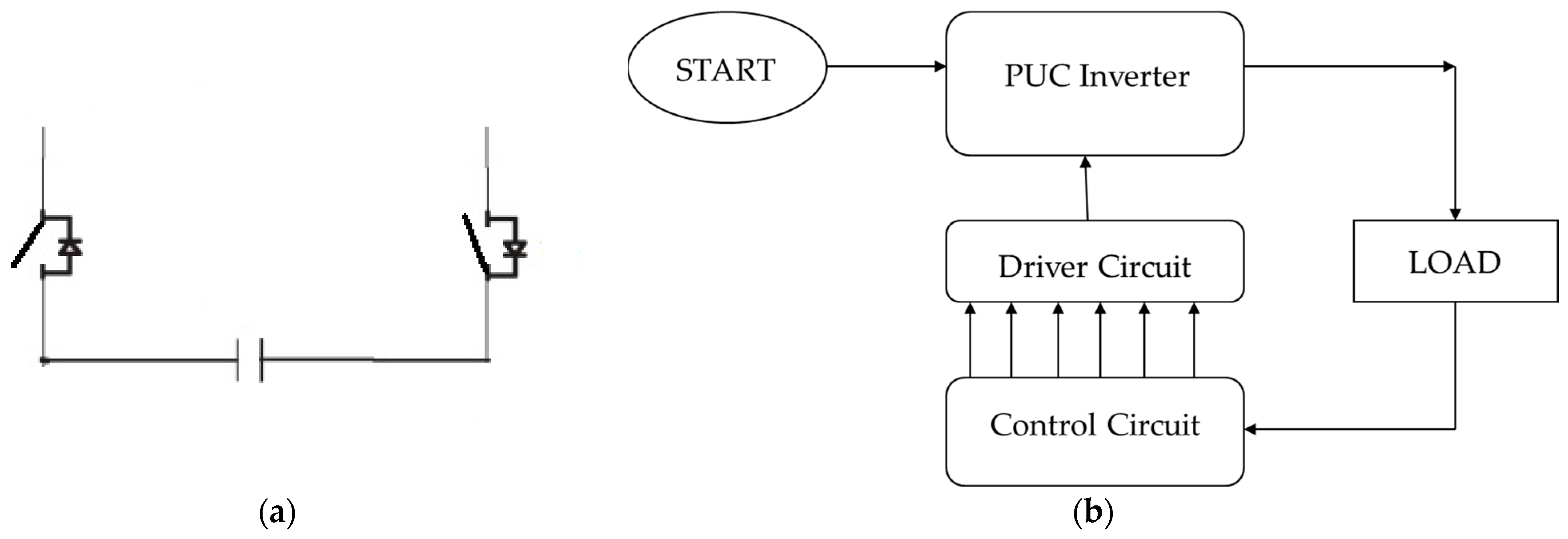
As distributed energy generation has started flourishing, the need for efficient power conversion is very rapidly growing; thus, development in the power electronics field is inevitable. Multi-level inverters are a promising solution for effective high-power exchange with low harmonic content and reduced switching losses. Conventional MLIs have many demerits, which include: i) implementation cost; ii) complexity of design with an increase in voltage levels; and iii) the number of solid-state devices increases with voltage levels. As there are difficulties, there are also opportunities for improvement. A lot of research has been carried out in designing efficient multi-level inverters, and one among them is the PUC design, which uses power switches and capacitors to form the basic U-cell unit. Such a design has both the advantages of a cascaded H-Bridge (CHB) and flying capacitors (FC). Figure 1a reveals the components that make up the basic U-cell. It consists of one capacitor that connects two solid-state devices on either side.
As there are a lot of merits to the multi-level inverters, this paper proposes a 31-level MPUC inverter, which is gated in a dynamic manner by a variable switching frequency model predictive controller, which determines the switching states based on a cost function optimization for optimal grid current and capacitor voltages. This switching algorithm is implemented in a PIC microcontroller. The prediction efficiency of the switching algorithm is verified by simulation for 9-level and 31-level PUC inverters. There are multiple algorithmic implementations available in the literature for smaller-level MLIs where the number of switching states is smaller, whereas, in this paper, the cost function optimization has been used for switching a 31-level inverter efficiently. A 31-level design is prototyped, and the hardware results are verified.
2. Materials and Methods
The primary objective of using the multi-level inverters (MLI) is to increase the operating voltage and the current of the converters used. And, MLIs come with the advantages of higher operational voltage than the rated voltage of the components, stepped outputs with lower harmonic content, and reduced dv/dt changes. However, these MLIs come with a huge number of power switches that need to be reduced for optimizing cost and efficiency.
Packed U-cell (PUC) topologies are preferred over the other MLIs because of the reduced number of components used. For example, while considering a 9-level MLI, the components used by different inverter topologies are given in Table 1.
A varied number of stage-based MLIs were studied in the literature, ranging from 5-level PUCs in [11,14,37,41], 7-level PUCs in [19,22,23,24,28,39,40,42], 15-level PUCs in [19,25], 19-level PUCs in [36], and a 31-level PUC in [27], each being handled by different control mechanisms. As the number of steps in a PUC increases, the stress on the power switches decreases, as the handling voltage reduces. As the number of steps in the output increases, the total harmonic distortion (THD) tends to reduce. As the optimal function of the MLI is desired, a 31-level PUC inverter was considered for design, and the output quality was compared with a 9-level PUC in this work.
2.1. A 31-Level MPUC Inverter
A 31-level MPUC inverter circuit was designed, and its performance with respect to output voltage and the harmonics produced were analyzed. The proposed modified PUC inverter used five pairs of power electronic switches (S1–S6, S2–S7, S3–S8, S4–S9, and S5–S10) connected across the DC source connected to dc1 and three capacitors (C2, C3, and C4, respectively). Considering dc1 as a reference, then the other voltage levels are given as:
- dc2 = 7/15(dc1);
- dc3 = 3/15(dc1);
- dc4 = 1/15(dc1).
Figure 2 depicts the MLI design, and Table 2 lists the 31-level voltages’ steps that yield the desired output. The different voltage levels are:
The DC power available from the solar cells has to be converted to a usable form by power converters before being fed to the load or connected to the power grid. Effective conversion of DC to AC power depends on the efficiency of the inverter. Thus, highly efficient and low THD inverter designs are required. Thus, this work detailed an efficient MPUC inverter design verified by simulation and then validated by hardware prototype implementation.
2.2. Modulation Technique
The process of gating the solid-state devices’ ON and OFF in order to convert the input to the desired output form is called modulation. The modulation pulses are generated at different time intervals with different pulse widths based on some algorithm. The effective prediction of these pulses determines the nearness of the generated output to the desired output, and, thus, the modulation strategy plays an important role in the design of any power inverter/converter. In addition, the modulation algorithm should have good voltage quality and it should be simple, low-cost, and of modular design; at the same time, simultaneous switching of voltage levels is be avoided, and switching frequency should be reduced.
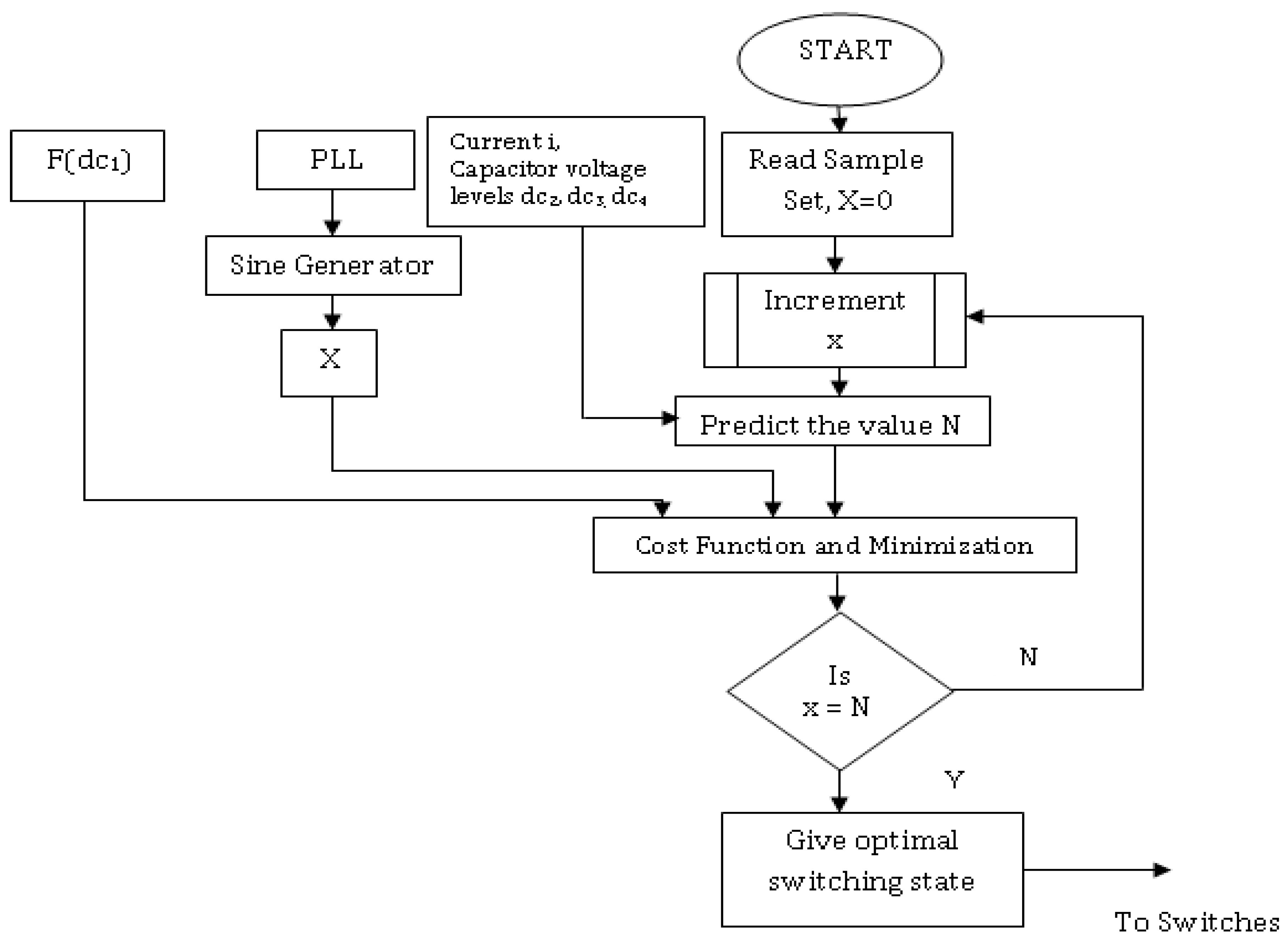
There are several modulation techniques used for switching the power devices in an MLI. These include Pulse Width Modulation (PWM) [21,23,25,34], Voltage balancing [11,33], Algorithmic-Controller-based PWM [37,38,40,41,42], and Artificial-Intelligence-based Controller [30,35,39]. In this work, a model predictive control algorithm was used to predict the width and instance of the switching pulses based on a reference sine wave. A model predictive control algorithm was used in this inverter, and its workflow is depicted below in Figure 3.
2.3. Model Predictive Controller
A model predictive controller gives the optimal switching state as the output, which gates the inverter switches. A prediction of the output is made from the present values of the load or the grid current I and the capacitor voltage levels dc2, dc3, and dc4. The cost function is determined from the DC reference voltage input dc1 and the sine wave generated from the PLL. If the error is minimal between the predicted and desired values, then the output is given, i.e., the switching pulses to trigger the power electronic switches are generated and given to the inverter.
2.4. Model Predictive Controller for 31-Level MPUC Inverter
The capacitor voltages dc2, dc3, and dc4 were at 7/15(dc1), 3/15(dc1), and 1/15(dc1), respectively. The switches (1,6), (2,7), (3,8), (4,9), and (5,10) were switched alternatively by the controller. The relationship between the load current i, the capacitor voltages dc2, dc3, and dc4, and the switching states represented by SWx are given by Equations (1)–(4). A 31-level inverter requires 5 different variables to represent all its switching states (say, sw1 to sw5, each carrying a value of 0 or 1). When sw1 is ‘0’, the switch S6 conducts, and when sw1 is ‘1’, S1 conducts. The variables that constitute the equations are defined as dc1, which is the voltage input from source; dc2, dc3, and dc4, which are the capacitor voltages; sw1 to sw5, which represent the switching states whose value takes up {1,0} for ON and OFF states, respectively; L, which is the inductance value; i(t), which is the grid or load current; vg(t), which is the grid voltage; and C2 to C4, which are the capacitances:
The objective of employing an MPC is to predict the capacitor voltages and the output current in order to switch the PUC inverter accordingly. Here, the term (k + 1) is the representation of the next state; thus, the next state of the voltage levels dc2, dc3, and dc4 in terms of the current ‘i’ and switching states are found by applying the Euler Approximation; they are given by Equations (5)–(8)
The maximum allowable error between the actual measurement and the prediction values of different state variables for the model predictive controller is formulated. The maximum state variations are used to obtain the normalized state variables, as in Equations (9)–(12), and the cost function is given by Equation (13).
Once the cost function is minimized, the prediction represented by (k + 1) and the reference values given by (*) will be very close to each other; furthermore, the output is given, i.e., the switching pulses to trigger the power devices are generated and given to the inverter.
3. Results
3.1. Simulation Results
3.1.1. Simulation of 9-Level MLI
The inputs used for the simulation of the nine-level MLI and the corresponding outputs are depicted below. Figure 4a–c represents the input current sources one, two, and three of the nine-level multi-level inverter. The ranges of the different input sources used are: (i) current sources one, two, and three, ranging up to 3.24 Amps; (ii) current source two, ranging up to 3.24 Amps; and (iii) input current source three, which is 3.24 Amps.
3.1.2. Output Voltage and Current
The simulation output of the nine-level MLI is as given below; Figure 5a represents the output voltage of the nine-level MLI, and it is approximately equal to 325 V. Figure 5b represents the output current whose value is 3.24 A. The Table 3 shows the Input and output values of 9-level MPUC inverter.
3.2. Simulation Result for the Proposed System
3.2.1. Input Sources
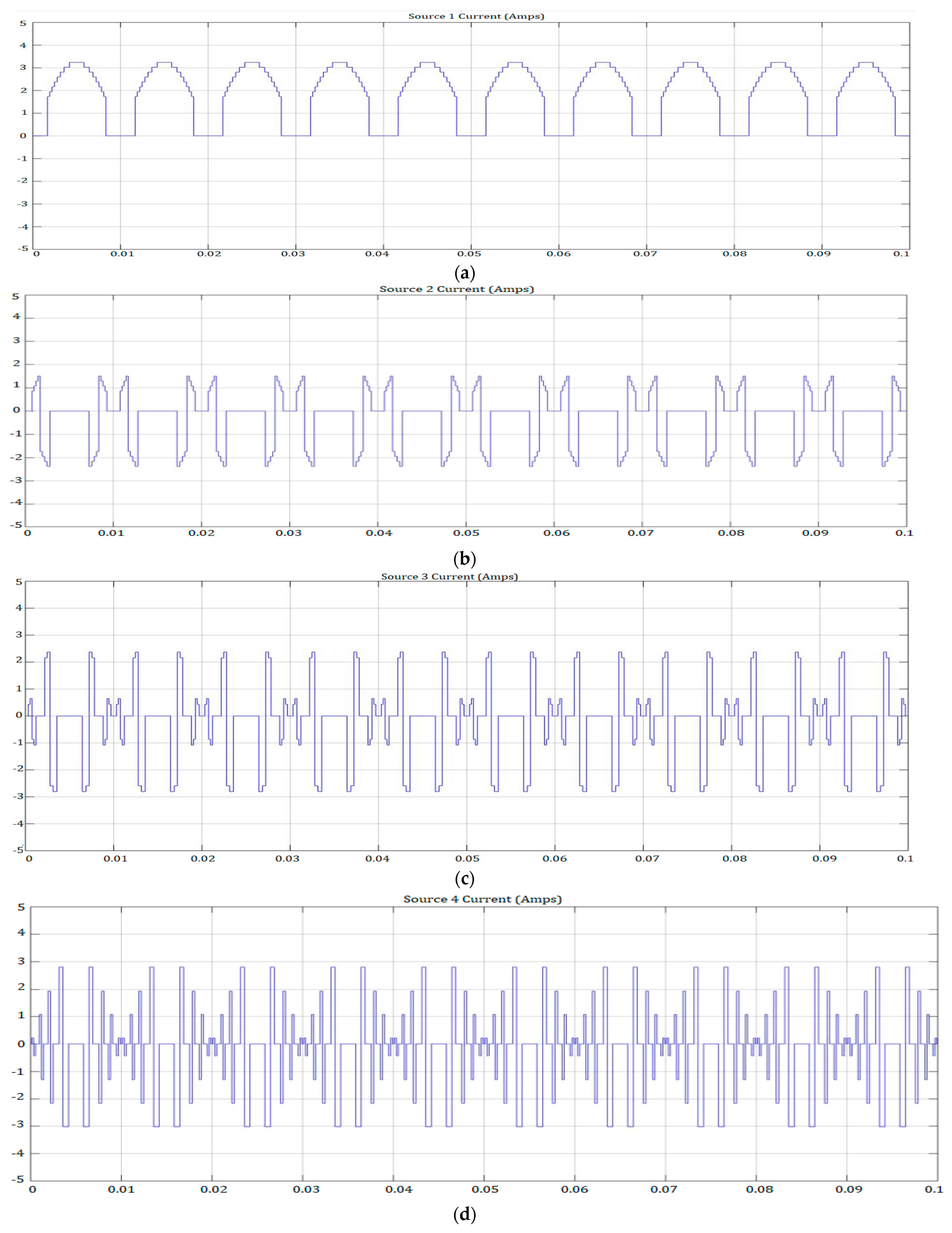
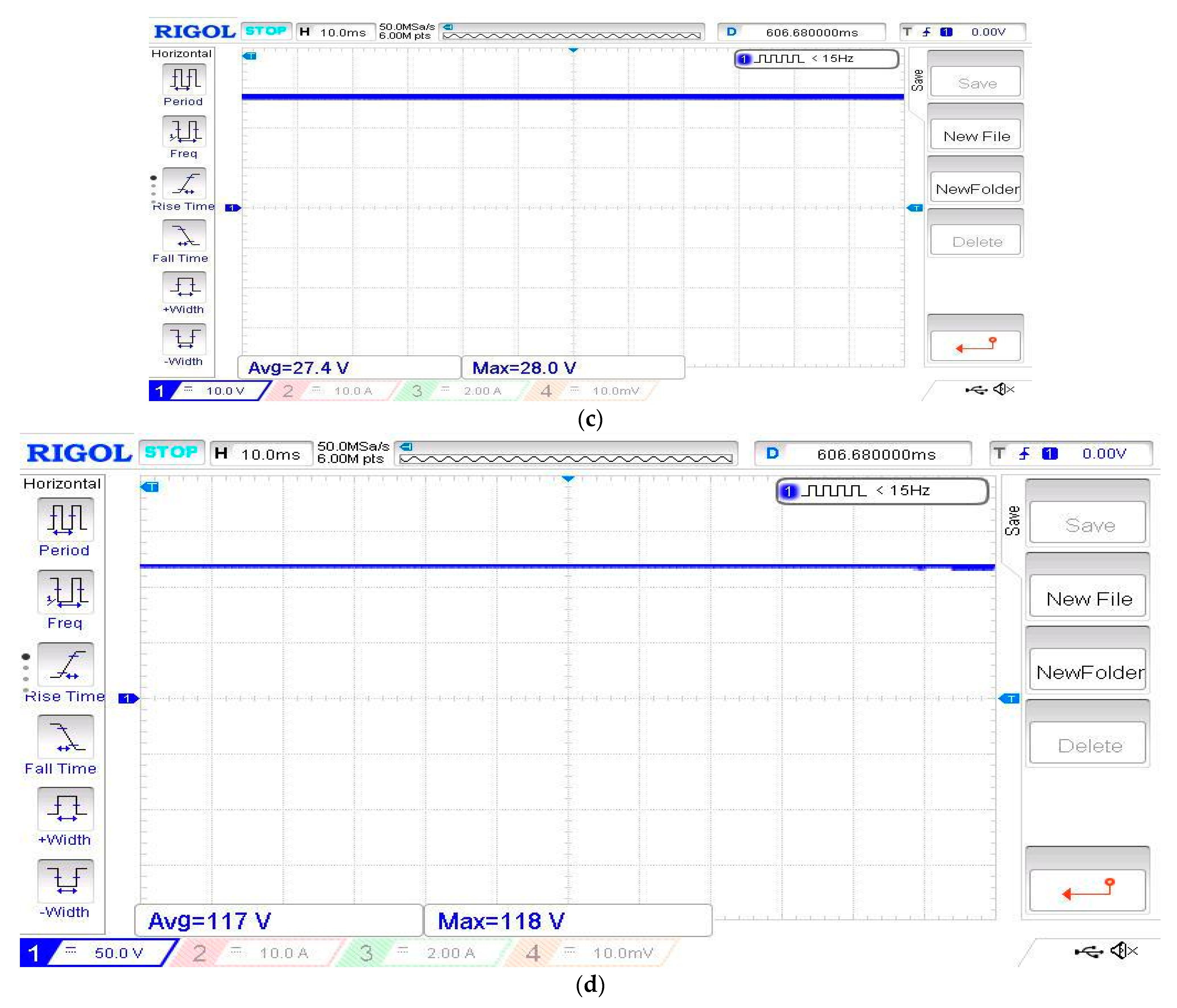
The inputs used for the simulation of the 31-level MPUC ML inverter are as given below. Figure 6a–d represents the input current sources one, two, three, and four of the 31-level MPUC MLI. The improvement in level shifting demands additional input sources in the circuit, and their corresponding values are: (i) current source one requires 3.24 A; (ii) input current source two ranges up to 1.5 A; (iii) current source three is approximately 2.3 A; and (iv) input current source four ranges up to 2.8 A. A varied range of input currents aids in providing performance improvement.
3.2.2. Output Voltage and Current
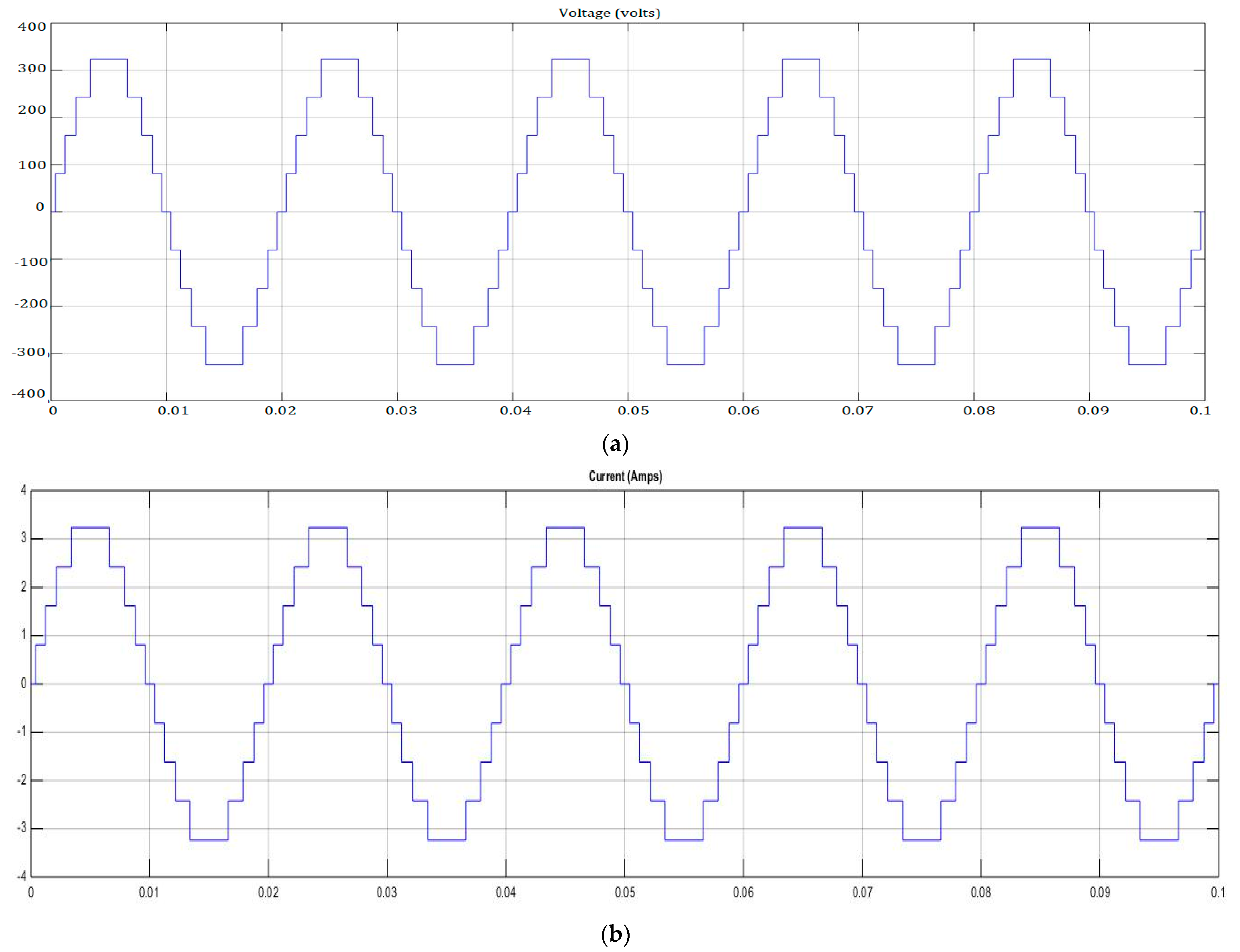
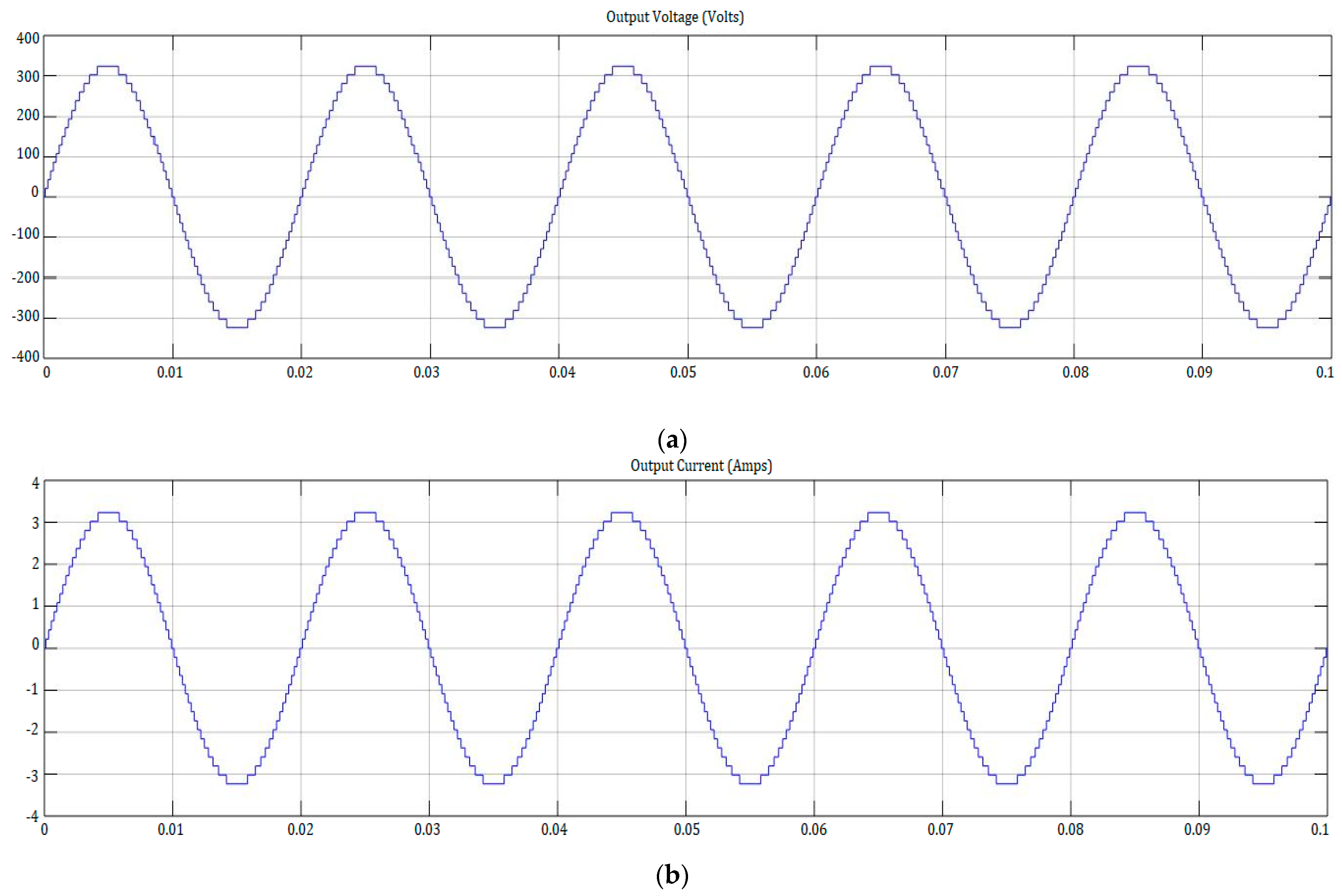
The simulation output of the 31-level MPUC multi-level inverter is as given below in Figure 7a,b. Figure 7a represents the output voltage of the 31-level multi-level inverter, and Figure 7b represents the output current. The 31-level MLI has an output voltage of 325 V with reduced switching loss and harmonic distortion. The overall output current for the 31-level MLI is 3.24 A. The Table 4 shows the Input and output values of 31-level MPUC inverter.
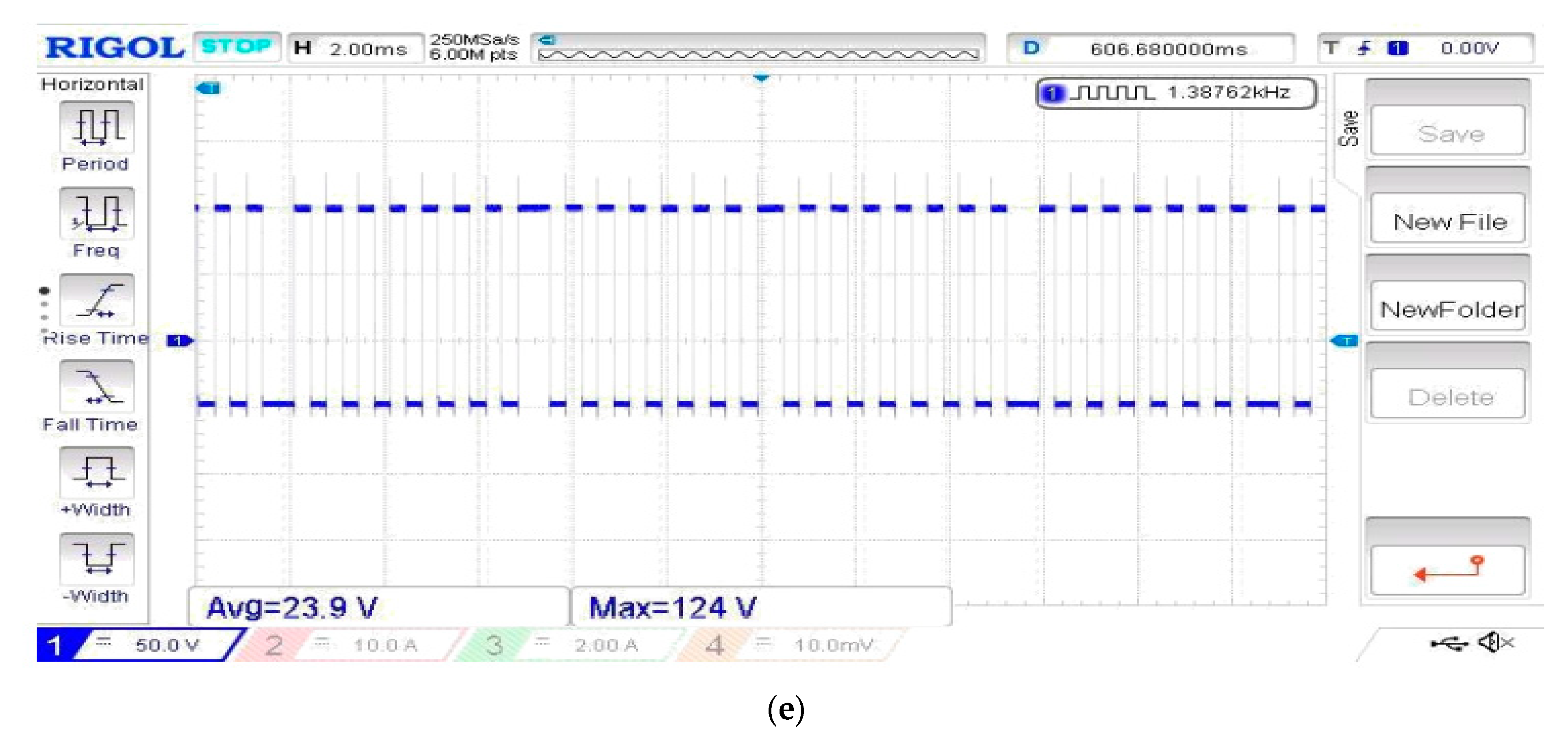
3.3. Total Harmonic Distortion Study by FFT Analysis
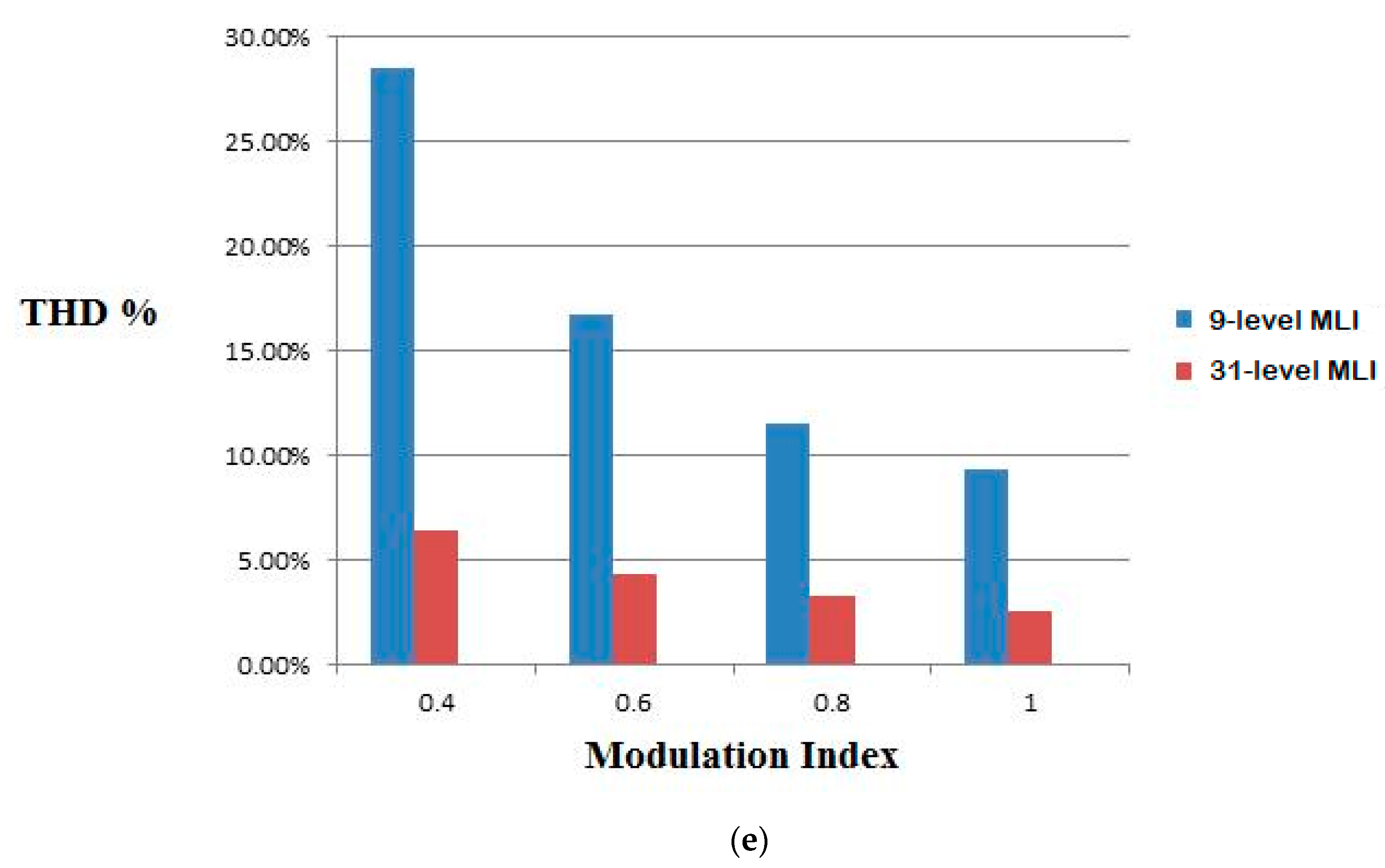
The simulation results of the FFT Analysis of the 31-level packed U-cell multi-level inverter for different modulation indices (say, 1, 0.8, 0.6, and 0.4) are depicted by Figure 8a–d. Table 5 represents the comparison table of the THD Analysis of the MLI. And, Figure 8e represents the comparison of the THD Analysis chart.
The simulation results reveal the output voltage current, which proves the efficiency of the 31-level MPUC MLI over its 9-level MLI counterpart. The FFT analysis proves that the harmonic distortions of the 31-level MPUC MLI for various modulation indices outperform its 9-level counterpart. The THD for the lowest modulation index of 0.4 for the 31-level MPUC MLI is 6.37%, whereas for the 9-level MLI, it is 28.51%. This proves the efficient harmonic reduction of the proposed design.
3.4. Hardware Results
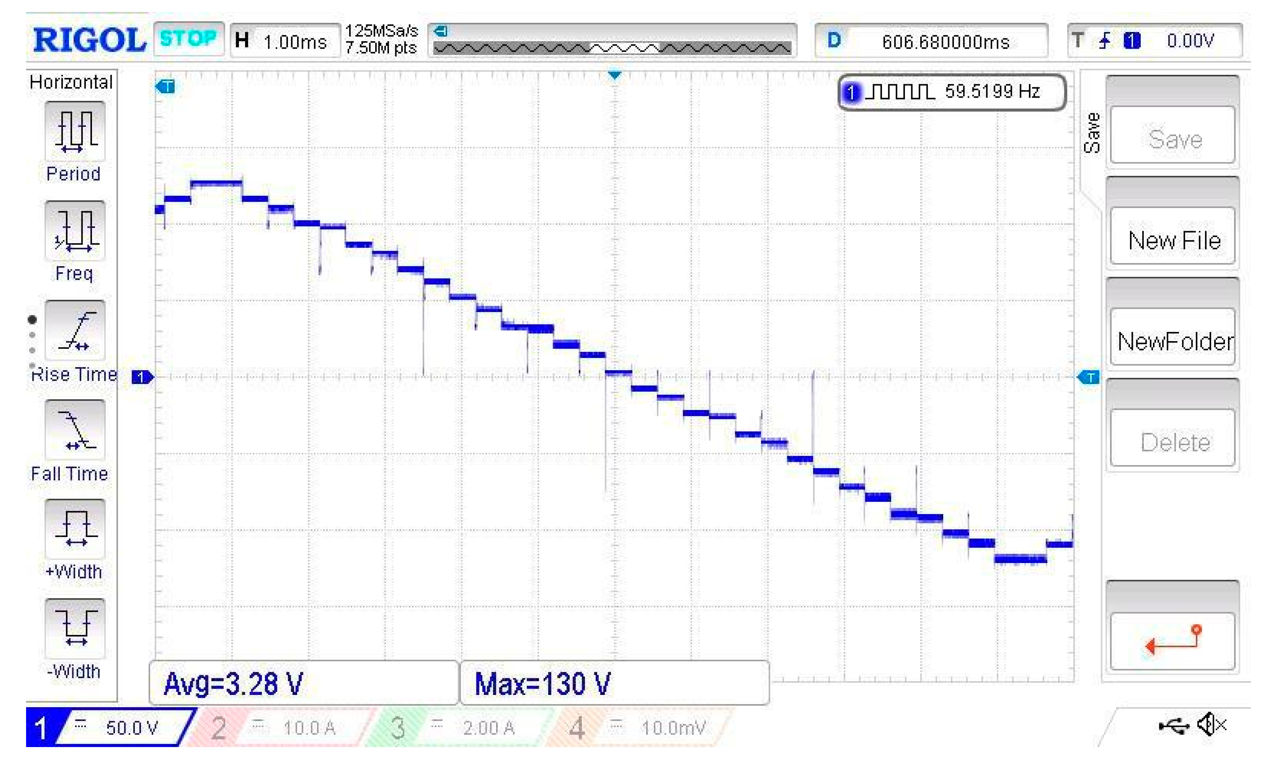
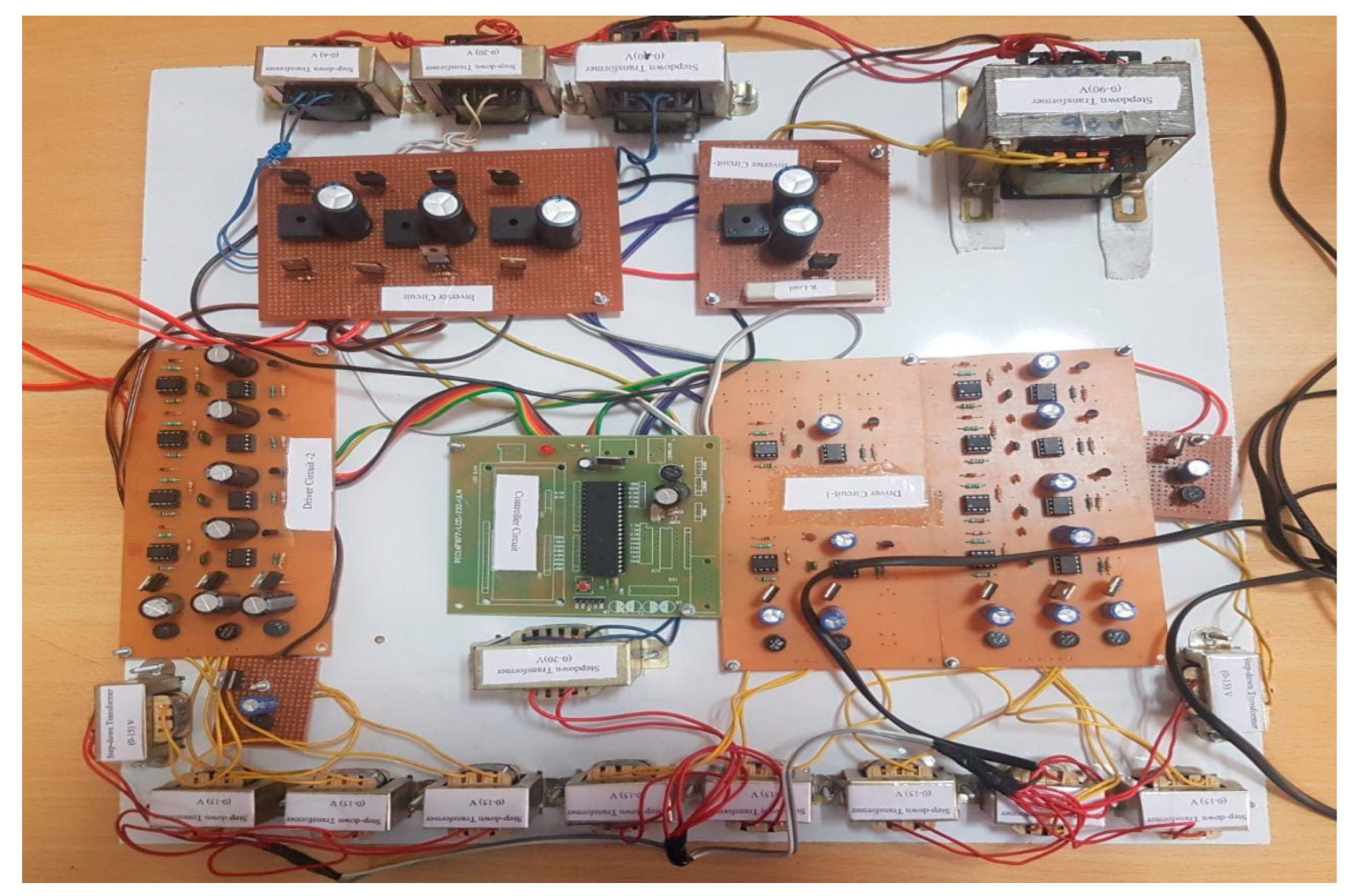
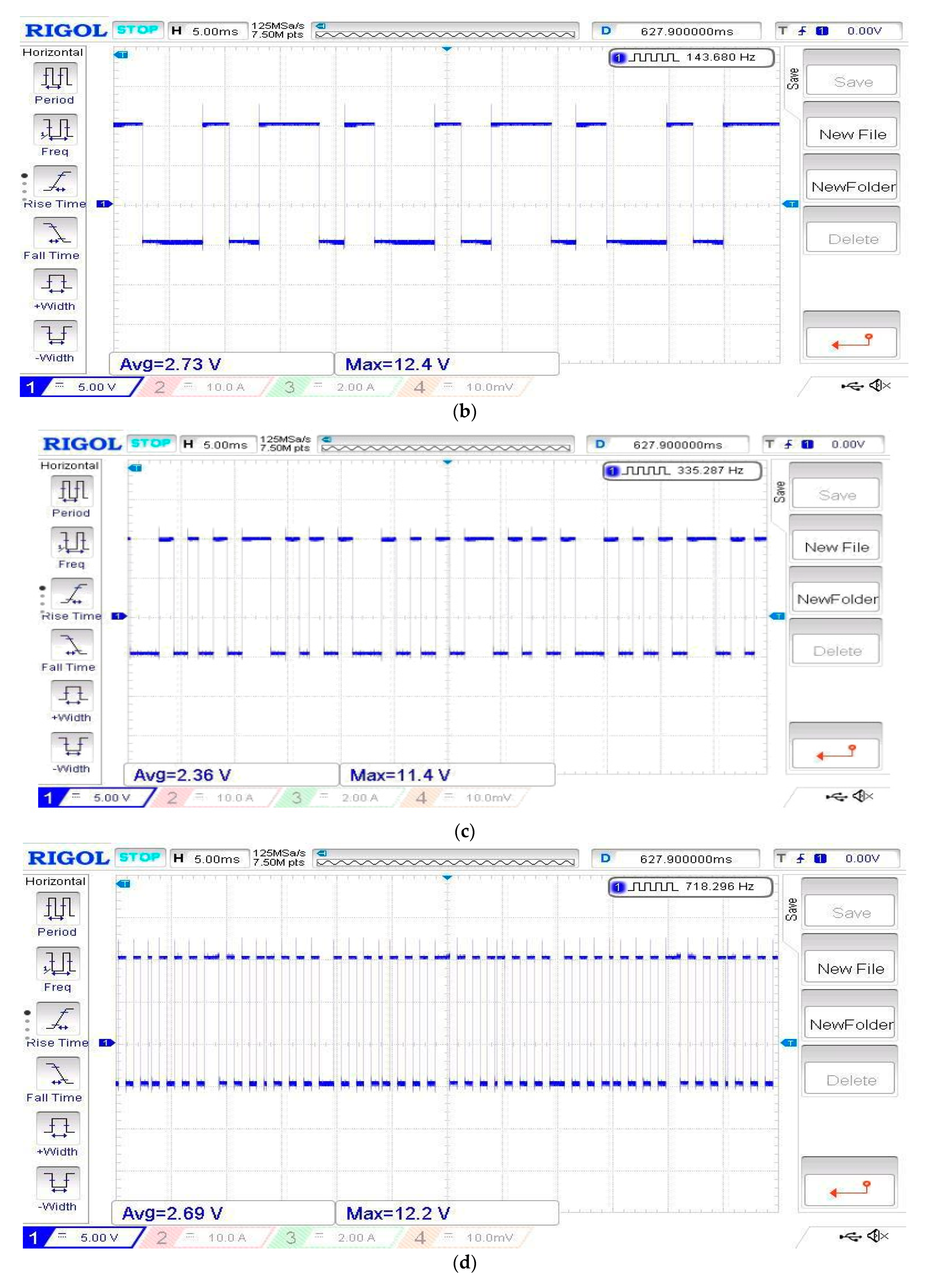
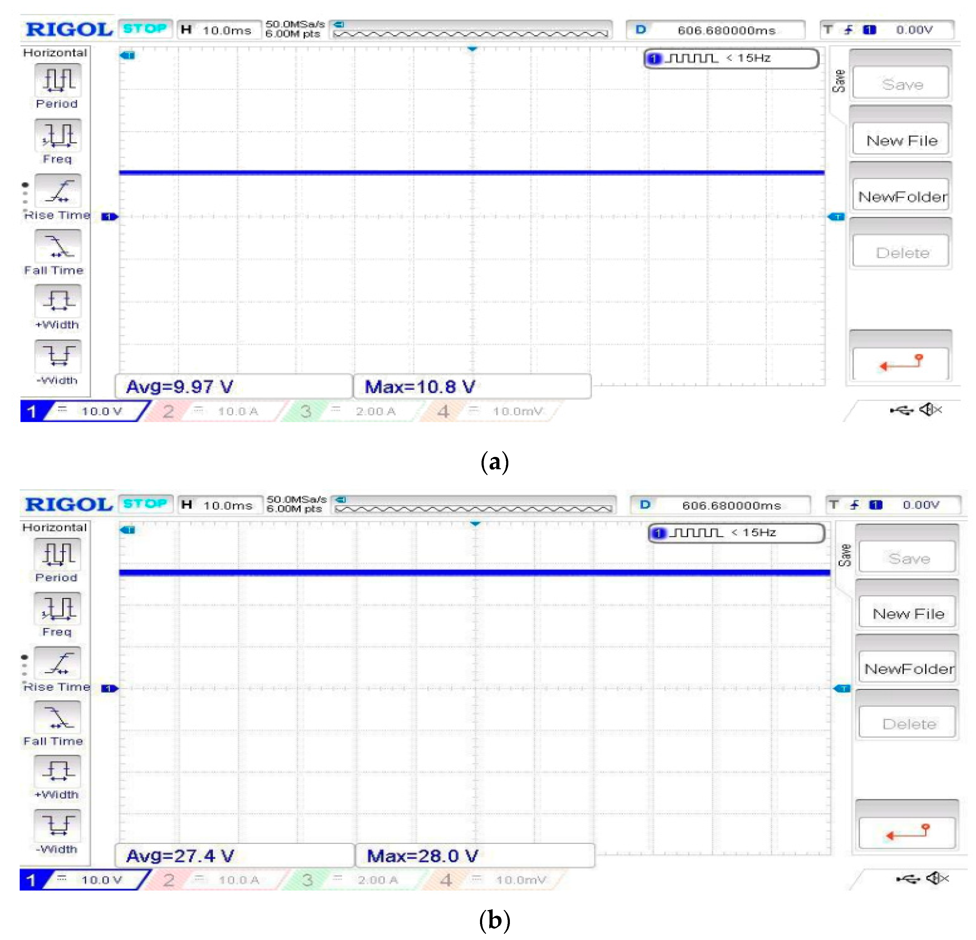
Considering the simulation results and the FFT analysis, it is found that the designed 31-level MPUC multi-level inverter performs better than the 9-level MLI. As a next step, a hardware prototype for the proposed model is designed, and the various input and output results are obtained. The model predictive control algorithm is implemented on a PIC microcontroller, and the hardware prototype results are obtained. The complete hardware setup of the 31-level MPUC MLI is given in Figure 9. Figure 10a–e shows the switching pulses that trigger that inverter circuit. Figure 11a–d represents the four inputs at the inverter circuit. The output of the inverter is given in Figure 12.
3.4.1. Switching Pulses
The modulation signals given to switches, their switching carried out, and their switching output pulses are observed. There are five switches, and their switching pulses are given by Figure 10a–e.
3.4.2. Input Source Voltage
The DC source voltage is given to the inverter as input after the rectification, several inputs are taken, and the system is operated. Thus, the conversion of source to input voltage is taken with the help of the rectifier circuit.
3.4.3. Multi-Level Inverter Output
Inverters convert the DC input voltage to AC voltage for utilization. The 31-level MPUC multi-level inverter output voltage with level shifts and improved efficiency with a minimum amount of THD is taken out with the help of DSO (Digital storage Oscilloscope), and the output is as shown by Figure 12.
4. Discussion
Solar energy is an abundant source for renewable energy generation. Still, the major limiting factor is the efficiency of the harvesting systems. In order to obtain maximum power from the solar generation units, almost every harvesting system tracks the maximum power point to achieve greater efficiencies. However, due to challenges in tracking, such as losses, oscillatory system behavior, sluggish system response, and low accuracy, the efficiency of the maximum power point tracking system is affected. Reducing the associated harmonics and minimizing oscillatory system responses are the two major areas of research that gain importance when it comes to optimizing distributed solar generation. The drawbacks are mainly related to the efficiency of the solid-state power converters used with the solar power generation unit; thus, efficient gating of these power devices plays a major role in determining the efficiency of the solar power generation system. Different control techniques have been used for this purpose, and the model predictive control method is one of the frequently used techniques due to its advantages. MPC-based switching techniques help improve power quality as they are devoid of filters, which are the major sources that affect the quality of power. Such MPC controllers, in addition to switching inverters, can be used to work along with maximum power point tracking for efficient and quick tracking. Thus, in this paper, a Variable Switching Model Predictive Controller implementation for a 31-level PUC multi-level inverter is presented with the objective of reducing the harmonics and improving power quality control. A model predictive controller is implemented using a PIC controller, and this is capable of providing a faster response under dynamic environmental conditions. Both the simulation and hardware results show a reduction in total harmonic distortion with increased step levels. The FFT analysis reveals that the total harmonic distortion for the lowest modulation index of 0.4 for the 31-level MPUC MLI is 6.37%, whereas for the 9-level MLI, it is 28.51%. Also, for a nominal modulation index of 0.8, the THD level is 11.54% and 3.27% for the 9-level MLI and the 31-level MPUC MLI, respectively. This depicts the reduction in total harmonic distortion achieved by the 31-level MPUC Inverter with model predictive control.
5. Conclusions
The modified multi-level PUC inverter (MPUC) can generate the output waveform in 31 steps, which helps reduce the low harmonic content in the output. Conventional MLIs have many demerits, which include: (i) implementation cost; (ii) complexity of design with increase in voltage levels; and (iii) the number of solid-state devices, which increases with voltage levels. Unlike the other available PUC topology, the proposed 31-level MPUC inverter uses a minimal number of power switches at the same time; therefore, it is capable of producing quality output voltage in terms of harmonic content. Also, the output power is greater, as it sums up the DC bus amplitudes. The efficiency of the system is attributed to the Variable Switching Model Predictive Control algorithm used for the generation of modulating pulses that switch the power devices in the inverter circuit efficiently. The significance of this design resides in the use of a reduced number of solid-state devices, capacitors, and filters; hence, this aids in compact and low-cost installations. The primary merit of using less switching and charging devices is to offer better power quality and reduced distortions. The FFT analysis results reveal that the total harmonic distortion THD is reduced for the 31-level design. This design can be further studied by (i) using different power switches, and (ii) using advanced prediction algorithms for switching inverters.
Author Contributions
Conceptualization, U.K. and U.P.; methodology U.K. and U.P.; software, U.K. and U.P.; validation, H.H.F. and E.R.; formal analysis, U.K. and U.P.; investigation, H.H.F. and E.R.; resources, H.H.F.; data curation, H.H.F. and E.R.; writing—original draft preparation, U.K. and U.P.; writing—review and editing, H.H.F. and E.R.; visualization, H.H.F. and E.R.; project administration, H.H.F. and E.R.; funding acquisition, E.R.; All authors have read and agreed to the published version of the manuscript.
Funding
This research received no external funding.
Data Availability Statement
No new data were created.
Acknowledgments
The work of Eugen Rusu was carried out in the framework of the research project DREAM (Dynamics of the REsources and Technological Advance in Harvesting Marine Renewable Energy), supported by the Romanian Executive Agency for Higher Education, Research, Development and Innovation Funding—UEFISCDI, grant number PN-III-P4-ID-PCE-2020-0008.
Conflicts of Interest
The authors declare no conflict of interest.
References
- Franquelo, L.G.; Rodriguez, J.; Leon, J.I.; Kouro, S.; Portillo, R.; Prats, M.A. The age of multilevel converters arrives. IEEE Ind. Electron. Mag. 2008, 2, 28–39. [Google Scholar] [CrossRef] [Green Version]
- Ribeiro, E.; Barbi, I. Harmonic Voltage Reduction Using a Series Active Filter Under Different Load Conditions. IEEE Trans. Power Electron. 2006, 21, 1394–1402. [Google Scholar] [CrossRef]
- Abu-Rub, H.; Holtz, J.; Rodriguez, J.; Baoming, G. Medium-Voltage Multilevel Converters—State of the Art, Challenges, and Requirements in Industrial Applications. IEEE Trans. Ind. Electron. 2010, 57, 2581–2596. [Google Scholar] [CrossRef]
- Kouro, S.; Malinowski, M.; Gopakumar, K.; Pou, J.; Franquelo, L.G.; Wu, B.; Rodriguez, J.; Perez, M.A.; Leon, J.I. Recent Advances and Industrial Applications of Multilevel Converters. IEEE Trans. Ind. Electron. 2010, 57, 2553–2580. [Google Scholar] [CrossRef]
- Ounejjar, Y.; Al-Haddad, K.; Grégoire, L.-A. Packed U Cells Multilevel Converter Topology: Theoretical Study and Experimental Validation. IEEE Trans. Ind. Electron. 2010, 58, 1294–1306. [Google Scholar] [CrossRef]
- Abu-Rub, H.; Mariusz, M.; Al-Haddad, K. Power Electronics for Renewable Energy Systems, Transportation and Industrial Applications; John Wiley & Sons: Hoboken, NJ, USA, 2014. [Google Scholar]
- Mohamad, A.S.; Mariun, N.; Sulaiman, N.; Radzi, M.A.M. A new cascaded multilevel inverter topology with minimum number of conducting switches. In Proceedings of the 2014 IEEE Innovative Smart Grid Technologies—Asia (ISGT ASIA), Kuala Lumpur, Malaysia, 20–23 May 2014; pp. 164–169. [Google Scholar] [CrossRef]
- Vahedi, H.; Kanaan, H.Y.; Al-Haddad, K. PUC converter review: Topology, control and applications. In Proceedings of the IECON 2015—41st Annual Conference of the IEEE Industrial Electronics Society, Yokohama, Japan, 9–12 November 2015; pp. 004334–004339. [Google Scholar] [CrossRef]
- Kumar, P.R.; Kaarthik, R.S.; Gopakumar, K.; Leon, J.I.; Franquelo, L.G. Seventeen-Level Inverter Formed by Cascading Flying Capacitor and Floating Capacitor H-Bridges. IEEE Trans. Power Electron. 2015, 30, 3471–3478. [Google Scholar] [CrossRef]
- Vazquez, S.; Rodriguez, J.; Rivera, M.; Franquelo, L.G.; Norambuena, M. Model Predictive Control for Power Converters and Drives: Advances and Trends. IEEE Trans. Ind. Electron. 2017, 64, 935–947. [Google Scholar] [CrossRef] [Green Version]
- Vahedi, H.; Labbé, P.-A.; Al-Haddad, K. Sensor-Less Five-Level Packed U-Cell (PUC5) Inverter Operating in Stand-Alone and Grid-Connected Modes. IEEE Trans. Ind. Inform. 2016, 12, 361–370. [Google Scholar] [CrossRef]
- Kumar, R.; Singh, B. Single Stage Solar PV Fed Brushless DC Motor Driven Water Pump. IEEE J. Emerg. Sel. Top. Power Electron. 2017, 5, 1377–1385. [Google Scholar] [CrossRef]
- Vahedi, H.; Al-Haddad, K. Method and System for Operating a Multilevel Inverter. U.S. Patent US9923484B2, 20 March 2018. [Google Scholar]
- Narendrababu, A.; Yalla, N.; Agarwal, P. A modified T-type single phase five-level inverter with reduced switch voltage stress. In Proceedings of the 2018 International Conference on Power, Instrumentation, Control and Computing (PICC), Thrissur, India, 18–20 January 2018; pp. 1–5. [Google Scholar] [CrossRef]
- Sulake, N.R.; Venkata, A.K.D.; Choppavarapu, S.B. FPGA Implementation of a Three-Level Boost Converter-fed Seven-Level DC-Link Cascade H-Bridge inverter for Photovoltaic Applications. Electronics 2018, 7, 282. [Google Scholar] [CrossRef] [Green Version]
- Kang, J.-W.; Hyun, S.-W.; Ha, J.-O.; Won, C.-Y. Improved Neutral-Point Voltage-Shifting Strategy for Power Balancing in Cascaded NPC/H-Bridge Inverter. Electronics 2018, 7, 167. [Google Scholar] [CrossRef] [Green Version]
- Lee, S.; Kim, J. Optimized Modeling and Control Strategy of the Single-Phase Photovoltaic Grid-Connected Cascaded H-bridge Multilevel Inverter. Electronics 2018, 7, 207. [Google Scholar] [CrossRef] [Green Version]
- Hu, J.; Shan, Y.; Guerrero, J.M.; Ioinovici, A.; Chan, K.W.; Rodriguez, J. Model predictive control of microgrids—An overview. Renew. Sustain. Energy Rev. 2021, 136, 110422. [Google Scholar] [CrossRef]
- Shyam, D.; Premkumar, K.; Sivamani, D.; Nazarali, A.; Narendiran, S.; Ramkumar, R. PUC Optimal Switching Strategies for Renewable Applications in Single Phase Inverter. In Proceedings of the IEEE 9th Uttar Pradesh Section International Conference on Electrical, Electronics and Computer Engineering (UPCON), Prayagraj, India, 2–4 December 2022; pp. 1–5. [Google Scholar] [CrossRef]
- Iqbal, H.; Tariq, M.; Sarfraz, M.; Anees, M.A.; Alhosaini, W.; Sarwar, A. Model predictive control of Packed U-Cell inverter for microgrid applications. Energy Rep. 2022, 8, 813–830. [Google Scholar] [CrossRef]
- Abarzadeh, M.; Peyghami, S.; Al-Haddad, K.; Weise, N.; Chang, L.; Blaabjerg, F. Reliability and Performance Improvement of PUC Converter Using a New Single-Carrier Sensor less PWM Method with Pseudo Reference Functions. Electrical and Computer Engineering Faculty Research and Publications. (681) 2021. Available online: https://epublications.marquette.edu/electric_fac/681 (accessed on 1 March 2023).
- Phukan, H.; Debela, T.; Singh, J. A modified seven-level cross-connected PUC boost multilevel inverter with reduced cost factor and device count. Int. J. Emerg. Electr. Power Syst. 2022. [Google Scholar] [CrossRef]
- Upreti, S.; Singh, B.; Kumar, N. Harmonics Minimization in PUC Type Solar Multilevel Converter with Multicarrier Switching Schemes. IETE J. Res. 2022. [Google Scholar] [CrossRef]
- Junior, S.C.S.; Jacobina, C.; Fabricio, E.L.L. A Single-Phase 35-levels Cascaded PUC Multilevel Inverter Fed by a Single DC-Source. In Proceedings of the IEEE Energy Conversion Congress and Exposition (ECCE), Vancouver, BC, Canada, 10–14 October 2021; pp. 2467–2474. [Google Scholar] [CrossRef]
- Muthukuri, N.K.; Mopidevi, S. Optimal Controller Design of PUC-15 MLI Topology for Smart Grid Applications with Reduced Power Components. In Proceedings of the International Conference on Smart Technologies and Systems for Next Generation Computing (ICSTSN), Virtual, 25–26 March 2022; pp. 1–4. [Google Scholar] [CrossRef]
- Owona, J.L.; Fendji, M.D.; Effa, J.Y.; Fankem, E.D.K. Control of Reduced Switches Count and Classical Multilevel Inverters: A Comparison. E3S Web Conf. 2022, 354, 02002. [Google Scholar] [CrossRef]
- Venkedesh, R.; Kumar, A.; Renukadevi, G. Multilevel Inverter Design with Reduced Switches & THD Using Fuzzy Logic Controller. Int. J. Electr. Electron. Eng. 2022, 9, 1–21. [Google Scholar] [CrossRef]
- Bellah, F.A.; Abouloifa, A.; Echalih, S.; Hekss, Z.; Naftahi, K.; Lachkar, I. Control Design of a Seven-Level Packed U Cell Inverter. IFAC-PapersOnLine 2022, 55, 677–682. [Google Scholar] [CrossRef]
- Khan, F.A.; Shees, M.M.; Alsharekh, M.F.; Alyahya, S.; Saleem, F.; Baghel, V.; Sarwar, A.; Islam, M.; Khan, S. Open-Circuit Fault Detection in a Multilevel Inverter Using Sub-Band Wavelet Energy. Electronics 2021, 11, 123. [Google Scholar] [CrossRef]
- Kumar, A.; Jain, S. Predictive Switching Control for Multilevel Inverter using CNN-LSTM for Voltage Regulation. ADBU J. Eng. Technol. (AJET) 2022, 11, 0110203197. [Google Scholar]
- Mukundan, C.M.N.; Jayaprakash, P.; Subramaniam, U.; Almakhles, D.J. Binary Hybrid Multilevel Inverter-Based Grid Integrated Solar Energy Conversion System with Damped SOGI Control. IEEE Access 2020, 8, 37214–37228. [Google Scholar] [CrossRef]
- Salem, M.; Richelli, A.; Yahya, K.; Hamidi, M.N.; Ang, T.-Z.; Alhamrouni, I. A Comprehensive Review on Multilevel Inverters for Grid-Tied System Applications. Energies 2022, 15, 6315. [Google Scholar] [CrossRef]
- Komurcugil, H.; Bayhan, S.; Guler, N.; Abu-Rub, H.; Bagheri, F. A simplified sliding-mode control method for multi-level transformerless DVR. IET Power Electron. 2022, 15, 764–774. [Google Scholar] [CrossRef]
- Azeem, A.; Ansari, M.K.; Tariq, M.; Sarwar, A.; Ashraf, I. Design and Modeling of Solar Photovoltaic System using Seven-Level Packed U-Cell (PUC) Multilevel Inverter and Zeta Converterfor Off-Grid Application in India. Electrica 2019, 19, 101–112. [Google Scholar] [CrossRef]
- Jeevanantham, Y.A.; Srinath, S. ANN Based Reduced Switch Multilevel Inverter in UPQC for Power Quality Improvement. Intell. Autom. Soft Comput. 2022, 33, 909–921. [Google Scholar] [CrossRef]
- Fahad, M.; Tariq, M.; Faizan, M.; Ali, A.; Sarwar, A.; Tafti, H.D.; Ahmad, S.; Mohamed, A.S.N. A Dual Source Switched-Capacitor Multilevel Inverter with Reduced Device Count. Electronics 2021, 11, 67. [Google Scholar] [CrossRef]
- Abari, I.; Hamouda, M.; Sleiman, M.; Slama, J.B.H.; Kanaan, H.Y.; Al-Haddad, K. Open-Circuit Fault Detection and Isolation Method for Five-Level PUC Inverter Based on the Wavelet Packet Transform of the Radiated Magnetic Field. IEEE Trans. Instrum. Meas. 2022, 71, 1–11. [Google Scholar] [CrossRef]
- Kaymanesh, A.; Chandra, A. Computationally Efficient MPC Technique for PUC-Based Inverters Without Weighting Factors. In Proceedings of the 2021 IEEE Industry Applications Society Annual Meeting (IAS), Vancouver, BC, Canada, 10–14 October 2021; pp. 1–5. [Google Scholar] [CrossRef]
- Mohamed-Seghir, M.; Krama, A.; Refaat, S.S.; Trabelsi, M.; Abu-Rub, H. Artificial Intelligence-Based Weighting Factor Autotuning for Model Predictive Control of Grid-Tied Packed U-Cell Inverter. Energies 2020, 13, 3107. [Google Scholar] [CrossRef]
- Khawaja, R.; Sebaaly, F.; Kanaan, H.Y. Design of a 7-Level Single-Stage/Phase PUC Grid-Connected PV Inverter with FS-MPC Control. In Proceedings of the 2020 IEEE International Conference on Industrial Technology (ICIT), Buenos Aires, Argentina, 26–28 February 2020; pp. 751–756. [Google Scholar] [CrossRef]
- Sahli, A.; Krim, F.; Laib, A.; Talbi, B. Energy management and power quality enhancement in grid-tied single-phase PV system using modified PUC converter. IET Renew. Power Gener. 2019, 13, 2512–2521. [Google Scholar] [CrossRef]
- Trabelsi, M.; Ghanes, M.; Mansouri, M.; Bayhan, S.; Abu-Rub, H. An original observer design for reduced sensor control of Packed U Cells based renewable energy system. Int. J. Hydrogen Energy 2017, 42, 17910–17916. [Google Scholar] [CrossRef]
Figure 1.
(a) A basic U-cell; (b) Block diagram of MPUC multi-level inverter.

Figure 2.
A 31-level MPUC inverter.
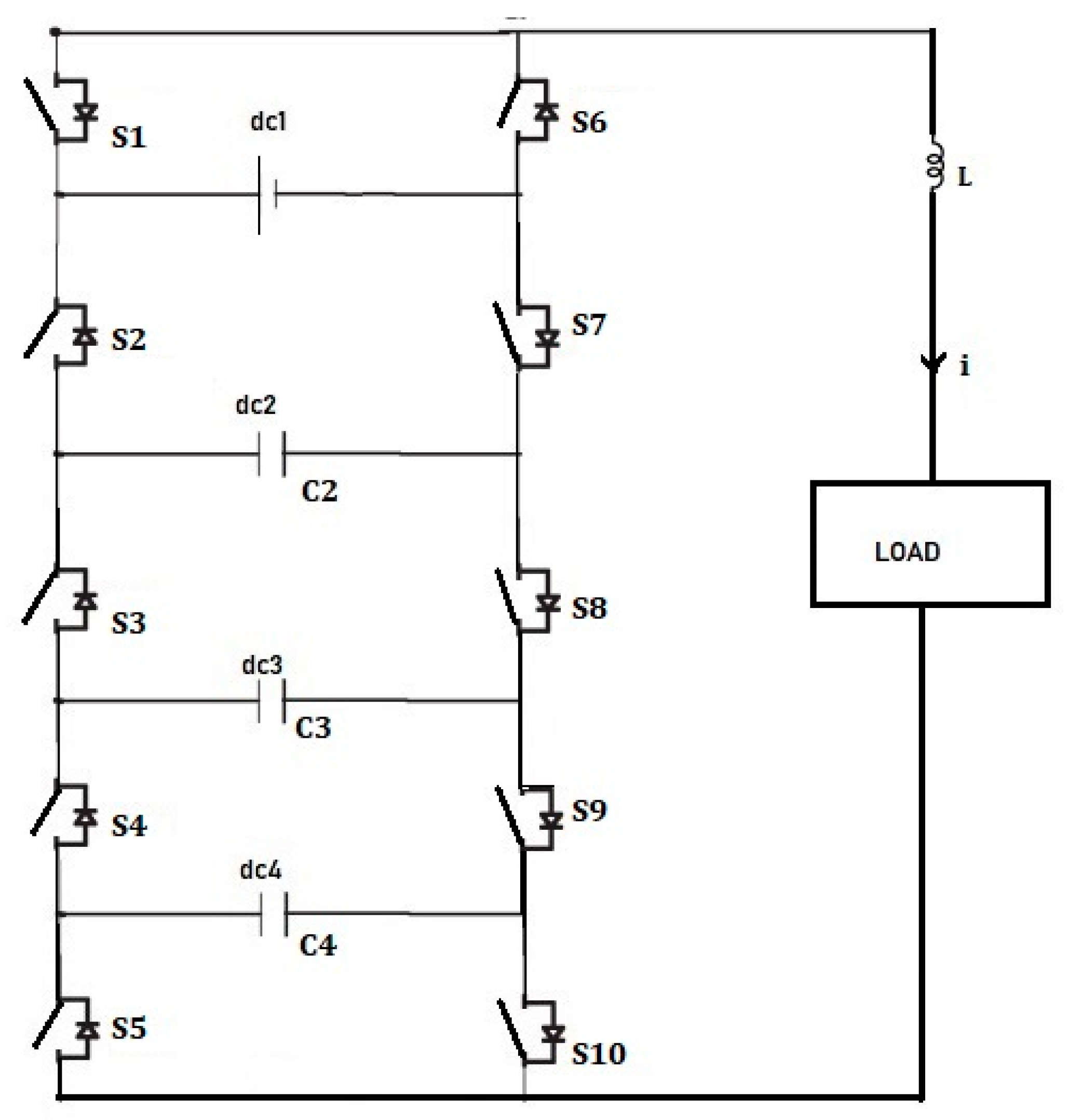
Figure 3.
Flow chart depicting the workflow of the model predictive controller.

Figure 4.
(a) Input source 1; (b) Input source 2; (c) Input source 3.
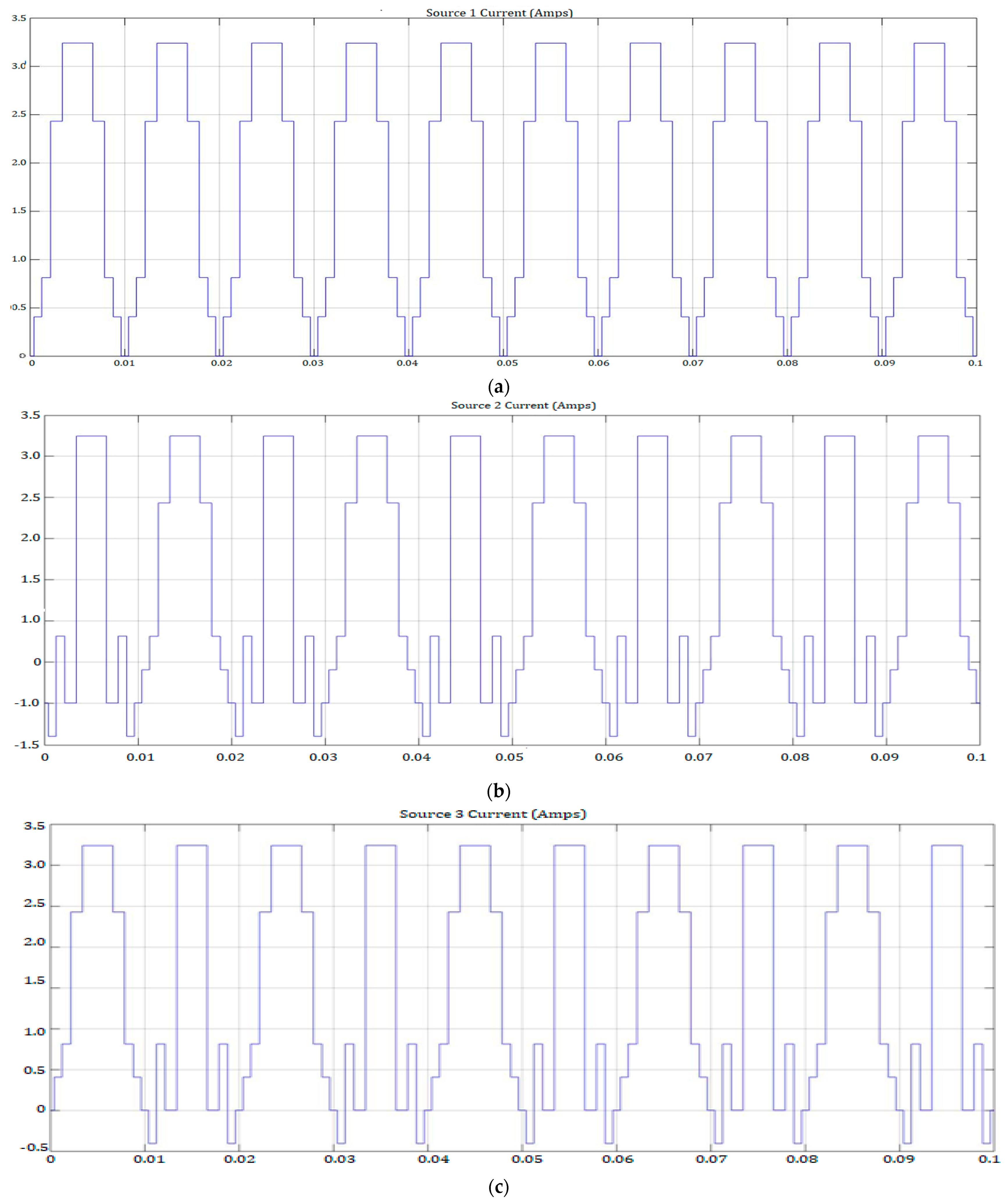
Figure 5.
(a) Output voltage; (b) Output current.

Figure 6.
(a) Input source current 1 = 3.24 A; (b) Input source current 2 = 1.5 A; (c) Input source current 3 = 2.3 A; (d) Input source current 4 = 2.8 A.
Figure 6.
(a) Input source current 1 = 3.24 A; (b) Input source current 2 = 1.5 A; (c) Input source current 3 = 2.3 A; (d) Input source current 4 = 2.8 A.

Figure 7.
(a) Output voltage, 325 V; (b) Output current, 3.24 A.

Figure 8.
(a) FFT Analysis for the modulation index 1; (b) FFT Analysis for the modulation index 0.8; (c) FFT Analysis for the modulation index 0.6; (d) FFT Analysis for the modulation index 0.4; (e) THD Analysis of various MIs for the conventional and proposed multi-level inverters.
Figure 8.
(a) FFT Analysis for the modulation index 1; (b) FFT Analysis for the modulation index 0.8; (c) FFT Analysis for the modulation index 0.6; (d) FFT Analysis for the modulation index 0.4; (e) THD Analysis of various MIs for the conventional and proposed multi-level inverters.
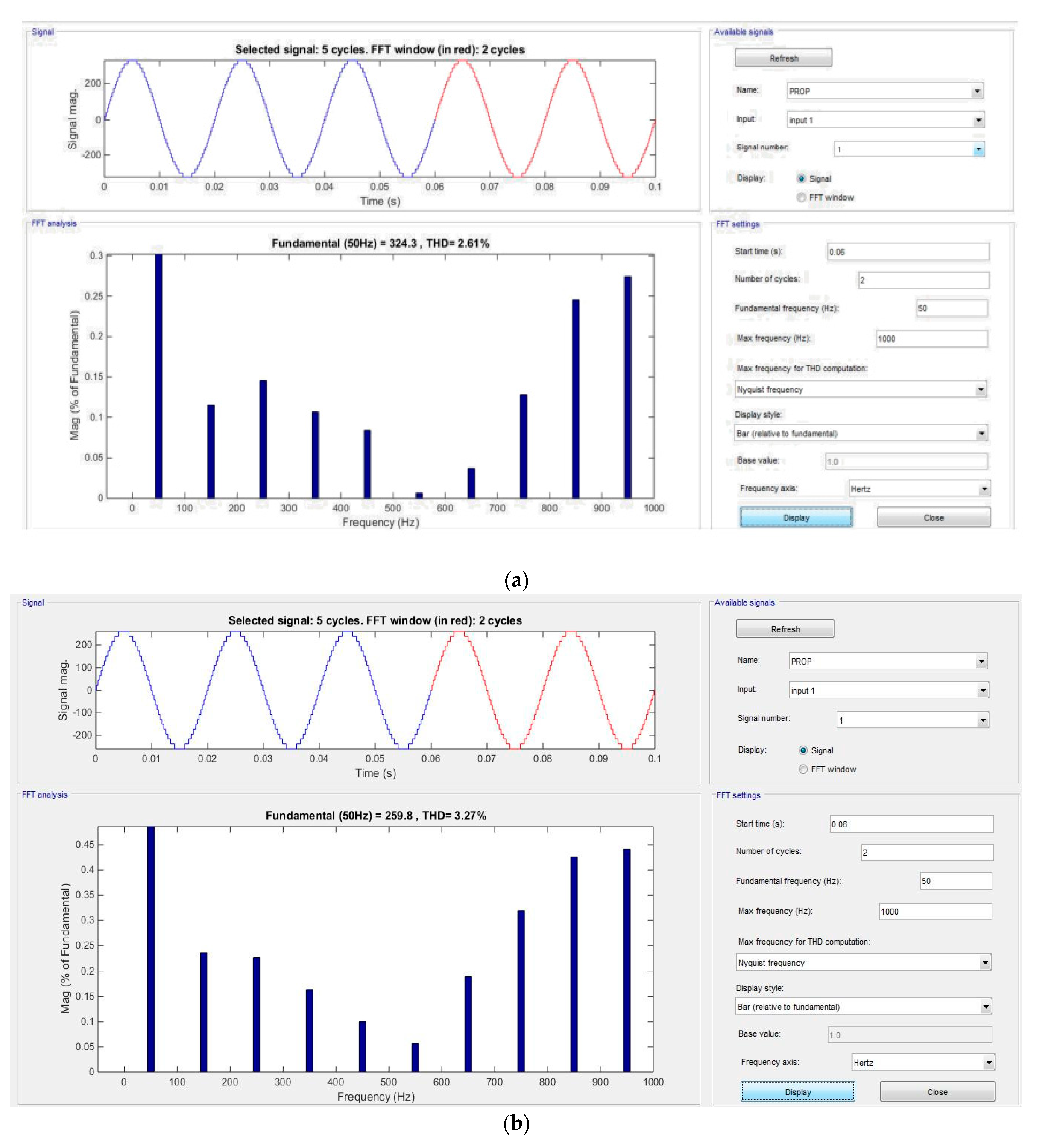


Figure 9.
Hardware prototype of the 31-level MPUC MLI.

Figure 10.
(a) Switch S1; (b) Switch S2; (c) Switch S3; (d) Switch S4; (e) Switch S5.
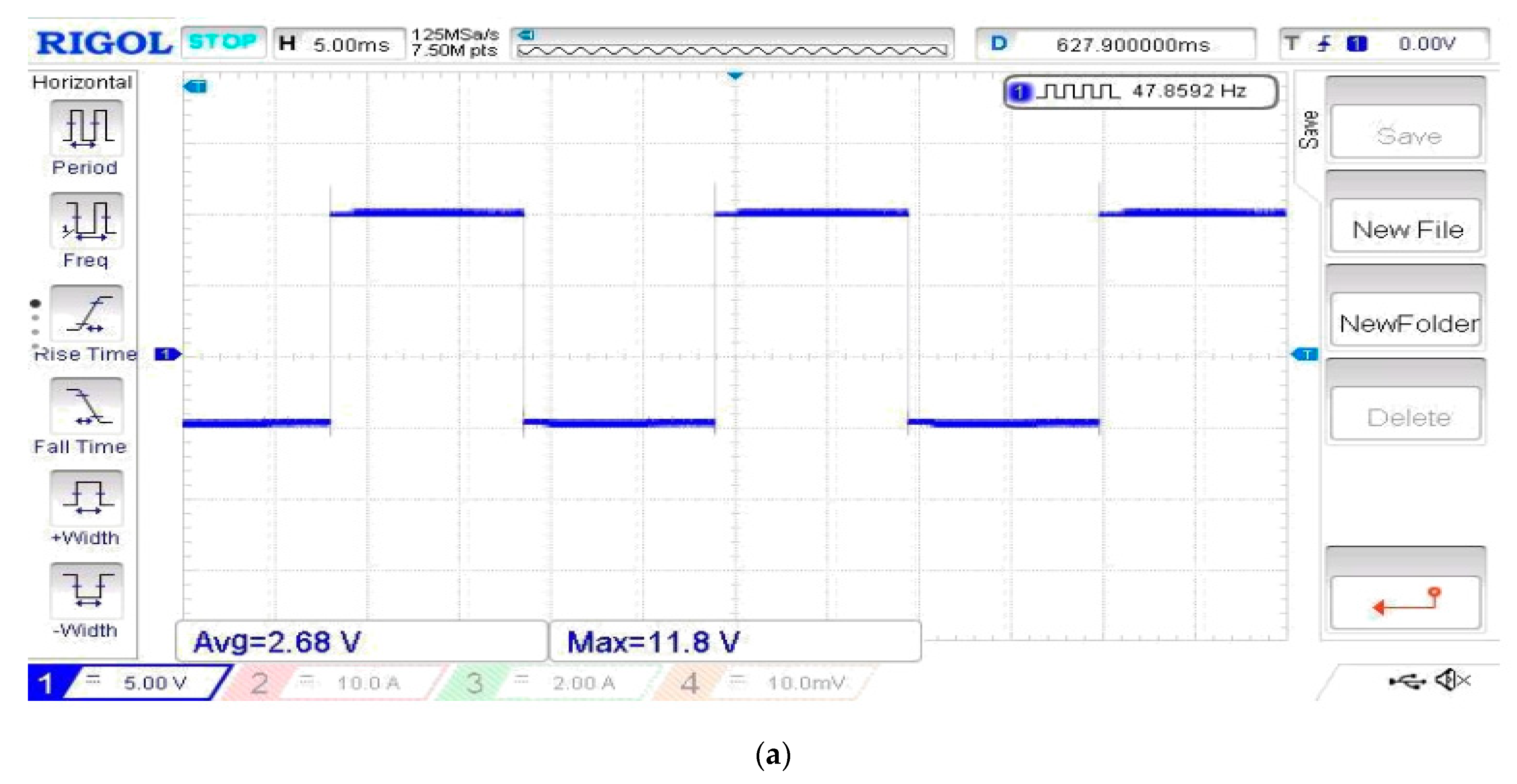


Figure 11.
(a) Source 1; (b) Source 2; (c) Source 3; (d) Source 4.


Figure 12.
Output voltage from the hardware prototype.

Table 1.
Components used by different inverter topologies.
| Inverter topology | Number of power switches | Number of capacitors | Number of dc sources |
| Manufacturer | Formax Electronics pvt ltd | Asoka Electronics | Generic Electronics |
| Component Description | 15 V, 1 A MOSFET switches | 1000uF/100V Electrolytic Capacitor | KBPC1510 15 A 1000 V Bridge Rectifier |
| Packed U Cell | 8 | 2 | 1 |
| Cascaded H Bridge | 16 | 0 | 4 |
| Flying Capacitor | 16 | 36 | 1 |
Table 2.
Voltage levels of the 31-level MPUC inverter.
| ±(-dc4) | ±(-dc3 + dc4) | ±(-dc3) | ±(-dc2 + dc3) | ±(-dc2 + dc3-dc4) |
| ±(-dc2 + dc4) | ±(-dc2) | ±(-dc1 + dc2) | ±(-dc1 + dc2-dc4) | ±(-dc1 + dc2-dc3 + dc4) |
| ±(-dc1 + dc2-dc3) | ±(-dc1 + dc3) | ±(-dc1 + dc3-dc4) | ±(-dc1 + dc4) | ±(-dc1) and zero |
Table 3.
Input and output of 9-level MPUC inverter.
| Input Current (Peak) in Amps | Output (Peak Values) | |||
|---|---|---|---|---|
| Source 1 | Source 2 | Source 3 | Voltage in V | Current in I |
| 3.24 | 3.24 | 3.24 | 325 | 3.24 |
Table 4.
Input and output of 31-level MPUC inverter.
| Input Current (Peak) in Amps | Output (Peak Values) | ||||
|---|---|---|---|---|---|
| Source 1 | Source 2 | Source 3 | Source 4 | Voltage in V | Current in I |
| 3.24 | 1.5 | 2.3 | 2.8 | 325 | 3.24 |
Table 5.
MI and THD for 9-level and 31-level multi-level inverters.
| Si. No. | Modulation Index | 9-Level THD% | 31-Level THD% |
|---|---|---|---|
| 1 | 0.4 | 28.51% | 6.37% |
| 2 | 0.6 | 16.71% | 4.31% |
| 3 | 0.8 | 11.54% | 3.27% |
| 4 | 1.0 | 9.36% | 2.61% |
Disclaimer/Publisher’s Note: The statements, opinions and data contained in all publications are solely those of the individual author(s) and contributor(s) and not of MDPI and/or the editor(s). MDPI and/or the editor(s) disclaim responsibility for any injury to people or property resulting from any ideas, methods, instructions or products referred to in the content. |
© 2023 by the authors. Licensee MDPI, Basel, Switzerland. This article is an open access article distributed under the terms and conditions of the Creative Commons Attribution (CC BY) license (https://creativecommons.org/licenses/by/4.0/).
Share and Cite
MDPI and ACS Style
Krishnamoorthy, U.; Pitchaikani, U.; Rusu, E.; Fayek, H.H. Performance Analysis of Harmonic-Reduced Modified PUC Multi-Level Inverter Based on an MPC Algorithm. Inventions 2023, 8, 90. https://doi.org/10.3390/inventions8040090
AMA Style
Krishnamoorthy U, Pitchaikani U, Rusu E, Fayek HH. Performance Analysis of Harmonic-Reduced Modified PUC Multi-Level Inverter Based on an MPC Algorithm. Inventions. 2023; 8(4):90. https://doi.org/10.3390/inventions8040090
Chicago/Turabian StyleKrishnamoorthy, Umapathi, Ushaa Pitchaikani, Eugen Rusu, and Hady H. Fayek. 2023. "Performance Analysis of Harmonic-Reduced Modified PUC Multi-Level Inverter Based on an MPC Algorithm" Inventions 8, no. 4: 90. https://doi.org/10.3390/inventions8040090