
Global Navigation Satellite System Spoofing Detection in Inertial Satellite Navigation Systems


Flight-Navigation and Information-Measuring Systems Department, Moscow Aviation Institute (National Research University), 125993 Moscow, Russia
*
Author to whom correspondence should be addressed.
Inventions 2023, 8(6), 158; https://doi.org/10.3390/inventions8060158
Submission received: 31 October 2023
/
Revised: 1 December 2023
/
Accepted: 12 December 2023
/
Published: 16 December 2023
(This article belongs to the Special Issue Recent Advances and New Trends in Signal Processing)
Abstract
:The susceptibility of global navigation satellite systems (GNSSs) to interference significantly limits the possibility of their use. From the standpoint of possible consequences, the most dangerous interference is the so-called spoofing. Simultaneously, in most cases of GNSS use, an inertial navigation system (INS) or an attitude and heading reference system (AHRS) is also present on the board of mobile objects. In this regard, the research goal is to assess the possibility of detecting GNSS spoofing in inertial satellite navigation systems. This paper examines the method for detecting GNSS spoofing by combining a pair of commercially available GNSS receivers and antennas with an INS or AHRS. The method is based on a comparison of the double differences of GNSS carrier phase measurements performed by receivers under conditions of resolved integer ambiguity and the values of the range double differences predicted using an INS. GNSS carrier phase integer ambiguity can be resolved using a strapdown inertial navigation system (SINS) or AHRS data. The mathematical model of GNSS phase difference measurements and the SINS-predicted satellite range differences model are given. The proposed algorithm calculates the moving average of the residuals between the SINS-predicted satellite range double differences and the measured GNSS carrier phase double differences. The primary criterion for spoofing detection is the specified threshold excess of the moving average of the double difference residuals. Experimental studies are performed using simulation and hardware-in-the-loop simulation. The experimental results allow us to evaluate the efficiency of the proposed approach and estimate the potential characteristics of the spoofing detection algorithm based on it.
1. Introduction
The global navigation satellite system (GNSS) is currently the primary navigation system onboard a wide range of moving objects. Simultaneously, it is known that GNSS is extremely susceptible to interference [1,2] arising from the propagation of a navigation signal from satellites to the receiver. Intentional interference should be considered the most dangerous, including from the standpoint of ensuring safety in aviation, sea, and land transport [1,2,3]. Traditionally, this type of interference is attributed either to interference leading to the suppression of navigation satellite signals (jamming) and, as a consequence, the inability to calculate navigation parameters, or to interference, represented by signals emitted by pseudolites that replace the signals of the GNSS space segment. The second type of interference is called spoofing; since the navigation receiver continues to calculate navigation parameters and the exact time, these values can be controlled by pseudolites when generating signals [2,3,4,5,6,7]. Thus, the task of spoofing detection is crucial.
An analytical review of existing methods and the results of experimental studies of interference detection in GNSS is given, for example, in [8,9,10,11,12,13,14]. A variety of approaches are used to detect GNSS spoofing. For example, spoofing detection based on clock bias or drift monitoring is described in [15,16]. A fundamentally different method based on abnormal energy in quadrature (Q) channel correlators is proposed in [17]. To detect a spoofing attack, the method proposed in [18] analyzes single-antenna GNSS and additional sensor (inertial measurement unit and odometer) measurements independently during a pre-selected observation window and cross checks the solutions provided by the GNSS and inertial navigation solution (INS)/odometer mechanization. But, as one of the most promising detection methods, a method based on determining the receiving direction of GNSS signals is considered. It implies the creation of a GNSS interferometer. Examples of the implementation and application of such systems are described in the papers in [8,12,19,20,21,22,23]. A significant disadvantage of GNSS spoofing detection methods based on analyzing the GNSS-signal-receiving direction exclusively by satellite measurements is the possibility that such detection is only possible if the spoofer emits radiation from one point in space. However, it is theoretically possible to create a navigation field that replaces real GNSS signals using several GNSS signal simulators. In this case, the spoof-emitting antennas are installed at different points in space. In the extreme case, each GNSS simulator can be made in a single-channel version and simulate the signal of only one satellite.
In this regard, this paper describes the results of a study of the method for detecting GNSS spoofing by combining a pair of commercially available GNSS receivers and antennas with an inertial navigation system (INS) or an attitude and heading reference system (AHRS). Commercially available receivers and antennas are common GNSS equipment that can be purchased from numerous manufacturers. This equipment is not made specifically to detect spoofing and does not even require modification for this. One of the measurements performed by the GNSS receiver is the carrier phase measurement. Moreover, the accuracy of such a measurement is generally at the level of several millimeters. By measuring the carrier phases of the signals received by the GNSS antennas mounted onboard at a distance from each other, it is possible to calculate a difference between these measurements. On the other hand, the satellite range difference can be calculated using information about the attitude angles from the INS and satellite ephemeris. Thus, if the source of the navigation signal is located at a point other than the location of the satellite calculated from the ephemeris, the measured and calculated phase differences will be different. Numerical control of this difference is the basis of the spoofing detection method used. Additional complexity is created by the presence of GNSS carrier phase integer ambiguity [24], which must be resolved in the algorithm of the complex system.
The paper is organized as follows: In Section 2, the mathematical model of the carrier phase and interferometric measurements in multi-antenna GNSS receiver equipment, as well as a description of the algorithm for detecting GNSS spoofing in inertial satellite navigation systems, is given. The methodology for the confirmation of the spoofing detection algorithm’s operability, including several scenarios, simulation results and hardware-in-the-loop simulation results, is presented in Section 3. A discussion of the experimental study results, including a comparison to the results of other recent studies, is given in Section 4. Section 5 is devoted to the research conclusions.
2. Materials and Methods
The research goal is to analyze the possibilities of detecting GNSS spoofing in inertial satellite navigation systems using carrier phase difference measurements performed by a pair of commercially available GNSS receivers and antennas installed onboard a mobile object. It is necessary to solve the following tasks in order to achieve the set goal:
- Developing a mathematical apparatus for the implementation of the spoofing detection algorithm;
- Developing a methodology for experimental studies of the developed algorithm’s capabilities;
- Conducting simulation in accordance with the developed methodology of experimental research;
- Analyzing the results of experimental studies with an assessment of the operability of the proposed technical solutions and the primary characteristics of the developed algorithm.
2.1. Model of Carrier Phase Measurements in Multi-Antenna GNSS Receiving Equipment
One should form a model of carrier phase measurements in multi-antenna receiving equipment to synthesize an algorithm for detecting spoofing in GNSS signals.
A mathematical model of the phase measurements of the satellite signal carrier j received by the antenna α can be represented as follows [24]:
where —the phase of the satellite signal j, measured by the antenna α; —the geometric distance from the antenna α to satellite j (m); —the error caused by inaccuracy of satellite ephemerides (m); —the speed of light in vacuum (m/s); —satellite clock error j (s); —receiver clock error α (s); —carrier wavelength of the GNSS signal (m); —integer ambiguity of the carrier phase; —ionospheric delay (m); —tropospheric delay (m); —phase measurement error caused by receiver noise; and —range measurement error caused by multipath [25].
The measurement model presented above assumes that the error in determining the carrier phase range is the sum of several errors caused by various factors. The error caused by the inaccuracy of satellite ephemerides is due to the finite accuracy of the ephemerides being manifested. The clock errors of the receiver and satellite should be considered as a shift of the corresponding clock from the GNSS system time. The shift of the satellite clock is caused by the systematic drift of the atomic clocks used on satellites. The delay of radio signals in the atmosphere causes another part of the errors. All errors mentioned above can be considered systematic errors with a certain degree of accuracy.
The reason for the occurrence of integer ambiguity is that the receiver can measure only a fractional part of the carrier phase, which is in the range from 0 to 2π, and is not able to measure the integer number of phase cycles that the electromagnetic wave has passed from the navigation satellite to the receiver antenna. In fact, in most equipment samples, the value of the phase range to the satellite issued at the first clock cycle after signal acquisition is the sum of the measured carrier phase (in the range from 0 to 2π) and a random number of integer cycles. At subsequent clock cycles, the receiver outputs the value of the phase range, taking into consideration changes in the integer number of cycles in no-cycle-slips conditions. In the case of cycle slip, the receiver measures the actual change in the entire cycle of the phase range with an error. Therefore, to use phase measurements, it is necessary to resolve the integer ambiguity present at the first epoch.
Signal phase measurement errors caused by receiver noise are usually in the range from 1 to 10 mm, while errors caused by multipaths are up to several cm. Possible phase tracking losses, which may be caused by multipath and signal shading, lead to the need to periodically re-resolve measurement ambiguity.
Another vital factor not taken into consideration in the model mentioned above but affecting the accuracy of the phase measurement is the stability of the phase center of the antenna. In the model presented above, it is assumed that the antenna is a material point. However, in real conditions, there are some deviations in the phase center of the antenna from its geometric center caused by the imperfection (non-spherical) of the radiation pattern (phase frequency response) of the antenna and the inaccuracy of its installation. Essentially, the phase of signals coming from satellites at the same range but having different elevation angles and azimuths will be different. In order to minimize the effects of the phase center instability effect, one should use the same type of antennas when forming the antenna block and ensure their identical orientation when installed. The distances between the antennas should also be chosen to be as large as possible. There is also a method in which the phase characteristics of each antenna are initially removed depending on the elevation angles and azimuth. In the future, this information will be used to correct measurements depending on the elevation angles and azimuth of the navigation satellite.
In many cases, using linear combinations of satellite signal measurements instead of direct measurements significantly improves the accuracy characteristics of relative positioning systems. One of the most effective methods of constructing such combinations, which makes it possible to eliminate clock errors, in both satellites and receivers, as well as ephemeris errors and errors due to delays in the atmosphere, is the construction of differences in the measurements of the signal of the same satellite produced by different receivers, and differences in the measurements of the signals of two different satellites produced by the same receiver.
Figure 1a demonstrates a graphical interpretation of the process of constructing the phase first differences “receiver-receiver”.
Assuming the absence of a multipath and recording the first receiver–receiver difference through the difference construction operator Δ, we can present its mathematical model as follows:
where —the difference in the phase measurements of the ranges from satellite j to antennas α and β; —the difference in the geometric ranges from satellite j to antennas α and β; —the difference in the clock errors of receivers α and β; —the difference in the values of the integer ambiguity of the phase measurements of receivers α and β; , —the difference in ionospheric and tropospheric delays in signal propagation from satellite j to antennas α and β; —the difference in phase measurement errors caused by the noise of receivers α and β.
Undoubtedly, after subtracting measurements from the same satellite made by different receivers, the satellite clock and ephemeris errors can be eliminated. Additionally, at small distances between the antennas, the residual effect of tropospheric and ionospheric refraction is extremely insignificant.
Figure 1b demonstrates a graphical interpretation of the process of constructing the phase first differences “satellite-satellite”. The mathematical model of the first satellite–satellite differences, written through the difference construction operator ∇, has the following form:
where —difference of ephemerides errors of satellites i and j; —difference of clock errors of satellites i and j.
Therefore, using the first satellite–satellite differences instead of direct phase measurements of the signals makes it possible to exclude the clock errors of the receivers.
Along with the method of constructing the first “receiver-receiver” differences described above, another method is based on an interferometric model for measuring radio signals. The interferometric model is based on the assumption of the flat nature of the propagation of the GNSS radio wavefront, while, in reality, the nature of the propagation of radio waves has the form of a growing sphere. Such an assumption is possible only if the distance from the satellites to the GNSS antennas significantly exceeds the distance between the antennas. Figure 2 illustrates a graphical interpretation of the interferometric method for constructing the first “receiver-receiver” differences.
The assumption of the flat nature of the propagation of the GNSS signal makes it possible to consider the vector directed from the base antenna to satellite j parallel to the vector directed from the remote antenna to the same satellite j. Thus, the difference in measurements made by the base and remote antennas will be equal to the scalar product of the vector located between the base and remote antennas and the unit vector directed from the remote antenna to satellite j:
The conducted studies [24] have shown that the interferometric method does not lead to any significant errors when the base length between the antennas is less than 100 m.
A single vector directed from a remote antenna to satellite j can be represented in an Earth-centered Earth-fixed (ECEF) coordinate system:
where —the projections of the radius vectors determining the position, respectively, of satellite j and receiver β on the axis of the ECEF coordinate system [26].
In Equation (4), the base vector between the antennas is expressed in ECEF coordinates. Nevertheless, using the direction cosines matrices between the body frame and local level () and between the local level [26] and ECEF () coordinate systems, this vector can also be represented in the body frame coordinate system:
Substituting Equations (6) and (5) into Equation (4) and then replacing the corresponding term of Equation (3) with the resulting expression for the first range difference, we obtain the equation for the phase first range difference:
Combining the method of constructing the first “receiver-receiver” differences with the method of constructing the first “satellite-satellite” differences, one can transition to the method of constructing the double differences. The mathematical model of the double difference of phase range measurements has the following form:
where —the operator for constructing the double difference by subtracting from the first “receiver-receiver” differences for satellite j the first “receiver-receiver” differences for satellite i.
Therefore, when constructing the double differences, the satellite clock error is excluded from the measurements. The values of the components , , and , representing the double differences in ephemeris, ionospheric, and tropospheric errors, are negligible (at the level of microns [24]), with a small length of bases between the antennas, and can be excluded. Simultaneously, when constructing the double differences, the error caused by receiver noise not only does not decrease but also doubles in comparison with direct phase measurements.
Interferometric measurements of signals from two satellites make it possible to construct the double differences of interferometric measurements. The mathematical model of the double differences of interferometric phase measurements has the following form:
where .
2.2. Algorithm for Detecting GNSS Spoofing in Inertial Satellite Navigation Systems
When synthesizing the algorithm for detecting GNSS spoofing in inertial satellite navigation systems, it has been assumed that the inertial navigation system is a strapdown system. The most important advantage of strapdown inertial navigation systems (SINSs) can be considered the ability to calculate attitude angles with relatively high accuracy (from hundredths to units of degrees). The accuracy of calculating these angles depends on the errors of the inertial measurement unit (gyroscopes and accelerometers). By having the values of the attitude angles at the time of the GNSS receivers performing phase measurements, one can calculate the predicted value of these measurements according to the SINS readings:
where —the direction cosines matrix between the body frame and local level coordinate systems, calculated from the values of the attitude angles (heading ψ, pitch ϑ, and roll γ) obtained from the SINS:
In this case, the vector and matrix can be calculated both from the SINS readings (provided that the SINS is corrected by GNSS) and from the coordinates (latitude and longitude) from the GNSS receiver obtained from code measurements:
where φ and λ are latitude and longitude.
In the absence of GNSS spoofing, the difference between the predicted value of the range double difference according to the SINS readings and its value measured using the carrier phase will depend only on the errors of the SINS and the errors of the phase measurements:
By accumulating the difference values, it is possible to calculate an estimate of the moving average, the expected value of which will be close to zero. The estimate of the moving average based on the last accumulated values of the phase differences at the time is calculated as follows:
On the other hand, in the case when the signals of the GNSS space segment are replaced by pseudolite signals that form a spoofing attack, the estimate of the moving average of the difference between the predicted value of the double range difference according to the SINS readings and the value measured using the carrier phase will differ significantly from the zero value. If the moving average estimate exceeds a certain threshold value, one can state the detection of spoofing.
Therefore, the criterion for the presence of spoofing can be represented as follows:
where the threshold is the threshold value after which an alarm about the presence of spoofing is generated.
The issue of resolving the integer ambiguity of GNSS phase measurements deserves special attention. When using this type of measurement as part of inertial satellite navigation systems, integer ambiguity is usually successfully eliminated due to information about the attitude angles from the SINS. Moreover, even SINSs based on low-grade gyroscopes manufactured using microelectromechanical system (MEMS) technology, with the distance between GNSS antennas not exceeding several meters, can be used to solve this issue. In fact, resolving ambiguity is also carried out by constructing the difference between Equations (10) and (9).
Figure 3 demonstrates a block diagram of the algorithm for detecting GNSS spoofing in inertial satellite navigation systems (, —receiver α and β ambiguous phase measurement vectors, containing pseudoranges to all satellites; —ambiguous phase measurement double differences vector; —unambiguous phase measurement double differences vector; —coordinates, calculated using code pseudoranges; —SINS-predicted range double differences vector).
This section describes a mathematical apparatus for implementing an algorithm for detecting GNSS spoofing in inertial satellite navigation systems by monitoring the difference phase measurements generated by a pair of satellite receivers and antennas, according to the readings of the INS. The proposed technical solutions require experimental verification. The conditions and results of experimental studies are provided in the next section.
3. Results
The operability confirmation of the proposed spoofing detection algorithm was carried out on the basis of simulation and hardware-in-the-loop (HIL) simulation.
3.1. Simulation Results
Simulation was conducted to evaluate the operability and main characteristics of the proposed algorithm for detecting GNSS spoofing in inertial satellite navigation systems. The research methodology assumes the simulation of the following processes:
- Trajectory of the moving object (linear motion of the center of mass and angular motion around the center of mass);
- Calculation of navigation satellites’ coordinates by ephemeris;
- Generation of GNSS code and phase measurements in the presence and absence of spoofing;
- Calculations of coordinates based on GNSS code measurements;
- Formation of measurements of SINS gyroscopes and accelerometers;
- Calculation of navigation parameters using the SINS algorithm;
- GNSS spoofing algorithm implementation in inertial satellite navigation systems.
An S-turn with parameters corresponding to the movement of a light aircraft was chosen as the trajectory.
The capabilities of the algorithm were investigated in several scenarios, taking into consideration the influence of the following factors:
- (1)
- Noise of phase measurements;
- (2)
- Distance between antennas;
- (3)
- The accuracy of SINS.
The possibility of detecting spoofing was investigated at a time interval of 100 s using GPS ephemerides. Figure 4 shows the configuration of the GPS constellation and the location of the pseudolites generating spoofing signals.
Figure 5 illustrates the values of the difference between the predicted value of the range double difference according to the SINS readings and its value measured using the GNSS carrier phase, obtained with the noise value of phase measurements of 0.002 m, and Figure 6 illustrates the results, obtained with the noise value of phase measurements of 0.01 m. The distance between the antennas is 1 m. The constant and noise component of gyroscope errors is 0.01 degrees/hour. The constant and noise component of accelerometer errors is 0.001 m/s2. The given results correspond to the G04-G22 satellites. Pseudolite 1 imitates the signal of satellite G04, and pseudolite 2 imitates the signal of satellite G22. The frequency of GNSS measurements is 10 Hz.
Figure 7 shows the values of the difference between the predicted value of the range double difference according to the SINS readings and its value measured using the GNSS carrier phase, obtained at a distance between the antennas of 2 m, and Figure 8 illustrates the results, obtained at the distance of 0.2 m. The noise of phase measurements is 0.002 m. The constant and noise component of gyroscope errors is 0.01 degrees/hour. The constant and noise component of accelerometer errors is 0.001 m/s2. The given results correspond to the G04-G22 satellites. Pseudolite 1 imitates the signal of satellite G04, and pseudolite 2 imitates the signal of satellite G22. The frequency of GNSS measurements is 10 Hz.
Figure 9 displays the values of the difference between the predicted value of the range double difference according to the SINS readings and its value measured using the GNSS carrier phase, obtained with constant and noise components of gyroscope errors of 0.001 degrees/hour and constant and noise components of accelerometer errors of 0.001 m/s2 (navigation grade SINS), and Figure 10 illustrates the results with constant and noise components of gyroscope errors of 5 degrees/hour and constant and random components of accelerometer errors of 0.01 m/s2 (low grade SINS). The distance between the antennas is 1 m. The noise of phase measurements is 0.002 m. The given results correspond to the G04-G22 satellites. Pseudolite 1 imitates the signal of satellite G04, and pseudolite 2 imitates the signal of satellite G22. The frequency of GNSS measurements is 10 Hz.
The graphs presented in this section illustrate the results of simulation performed based on the methods and scenarios described above for conducting experimental research on the possibilities of detecting GNSS spoofing in inertial satellite navigation systems. These data allow us to evaluate the performance of the proposed approach in detecting interference and evaluate the primary characteristics of the algorithm implemented on its basis.
Thus, based on the results of simulation modeling, it can be concluded that the difference between the moving averages remains practically at the same level (about 0.15 m on Figure 5 and Figure 6) for both carrier phase measurement noise of 0.002 m and noise of 0.01 m. At the same time, the measurement noise of 0.01 m can be considered even higher than its typical values. In this regard, even low-cost receivers can be used for spoofing detection. As expected, the difference between the moving averages increases with increasing distances between the antennas (0.3 m in Figure 7 with a baseline length of 2 m and 0.03 m in Figure 8 with a baseline length of 0.2 m). Therefore, to increase the probability of spoofing detection, it can be recommended to use as large antenna baselines as possible. At the same time, even with the baseline length at the GPS L1 wavelength level (Figure 7), it is still possible to reasonably choose the threshold for criterion (15). Finally, it can be argued that the probability of spoofing detection does not practically depend on the accuracy of the SINS (the moving average remains at 0.15 m for both the low-grade and navigation-grade SINSs in Figure 9 and Figure 10), at least for the selected time interval. This is because only the attitude angles from the SINS are needed to calculate the predicted values of the double differences. And their accuracy, even for low-grade SINSs, is sufficient to detect spoofing. However, it should be noted that over longer time intervals, a low-grade SINS can accumulate significant heading errors, which may affect the probability of spoofing detection.
3.2. HIL Simulation Results
To confirm the algorithm’s operability in the case of using real GNSS measurements, a HIL simulation was carried out.
The HIL simulation was carried out with the use of a small-sized integrated navigation system manufactured by MAI [27] (Figure 11) based on an inertial module DMU02 [28] manufactured by Silicon Sensing and a satellite navigation GLONASS/GPS receiver OEMV-1G [29] manufactured by NovAtel.
The HIL simulation scheme is presented in Figure 12. A pseudolite was used to simulate spoofing. The pseudolite signals were generated using the Navis SN-3803M GNSS signal simulator [30] (Figure 13) with its own scenario simulation software version 4.3. The radiation of the GNSS simulator signals was carried out using a GNSS repeater.
The study was conducted under static conditions and was carried out in several stages. In the first stage, the small-sized integrated navigation system was installed in the laboratory in conditions of good satellite visibility. Raw satellite and inertial measurements were sent to a personal computer (PC) for recording. In the second stage, a pseudolite was turned on. The GNSS simulator generated signals using a scenario exactly corresponding to the conditions of real GNSS satellite constellation raw measurements recording in the first stage. Raw GNSS measurements were also sent to a personal computer for recording in the second stage. In the third stage, the records were processed on a PC. Inertial measurements were used to implement the strapdown inertial navigation system algorithm. The spoofing detection algorithm was launched alternately with measurements from real GNSS satellite constellation and from a pseudosatellite.
The G29 satellite was chosen as the base satellite (Figure 14). The results of the spoofing detection algorithm implementation are shown in Figure 15, Figure 16 and Figure 17 To illustrate the results, one experiment was selected from a series of numerous experiments. The duration of recording measurements was 100 s.
Figure 15 shows the values of the unambiguous double differences of the GPS constellation phase measurements. The double differences of the satellites G20-G29, G11-G29, G12-G29, G05-G29, and G02-G29 were selected as the studied data. Figure 16 shows the values of the double differences formed by the signals of the pseudolite.
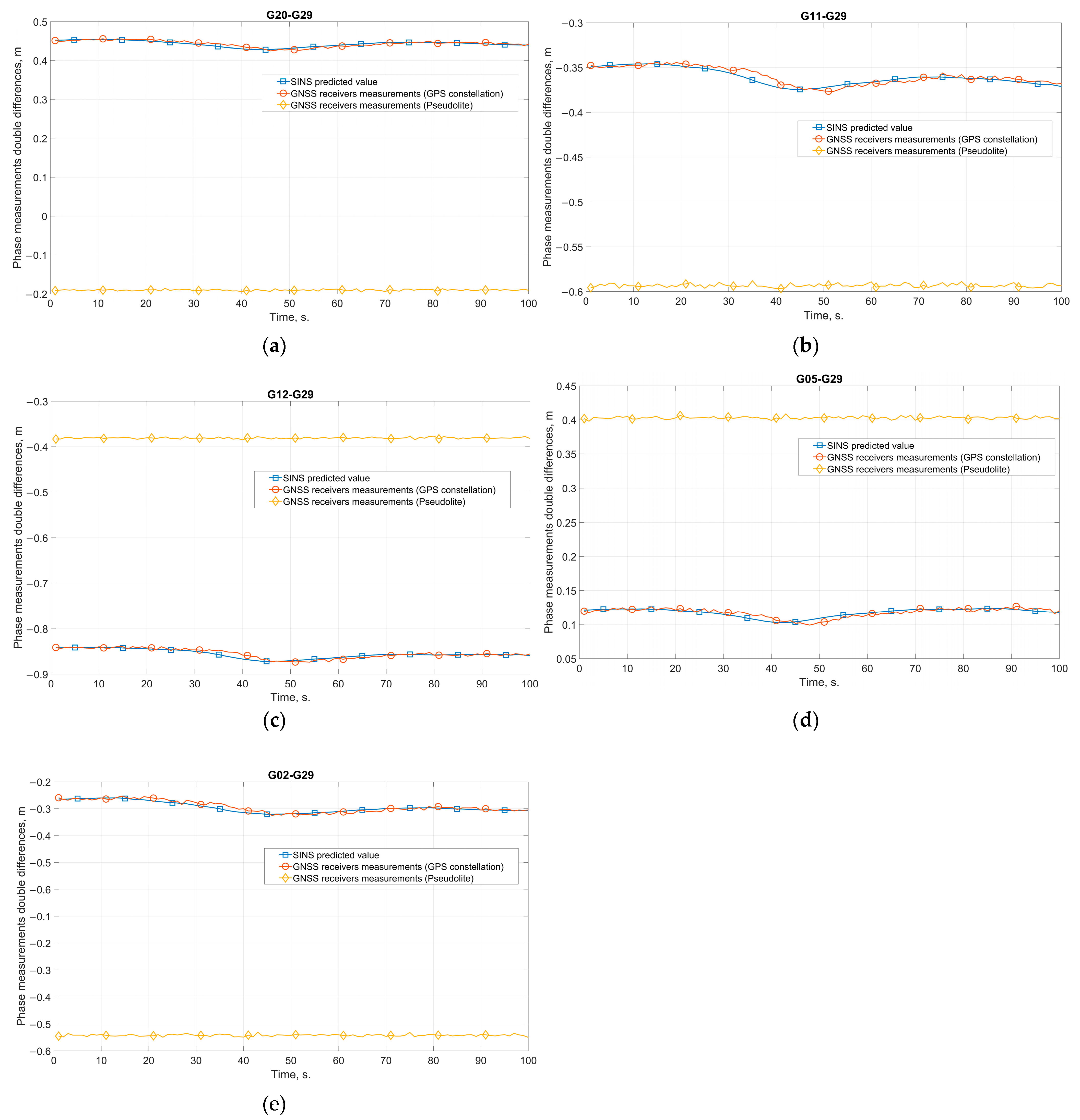
The analysis of the data shown in the figures confirms the operability of the developed algorithm based on the control of interferometric GNSS phase measurements. The values of the double differences measured by pseudolite signals and the SINS-predicted values of the double differences differ significantly. For a more detailed illustration, Figure 17 shows the SINS-predicted double differences and double differences measured by pseudolite signals for satellite pairs G20-G29, G11-G29, G12-G29, G05-G29, and G02-G29.
Table 1 summarizes the HIL simulation results in the form of the mean values of the differences (residuals) between the pseudolite double differences and the SINS-predicted double differences. The spoofing detection algorithm signaled the presence of spoofing for all satellite channels (the alert threshold value was in the range of 5–10 cm).
Thus, based on the test HIL simulation results, it is possible to draw a conclusion about the operability of the proposed spoofing detection concept and algorithm, as well as to estimate the time of the spoofing alert. During the tests, the time required to detect spoofing was in the range of 3 to 5 epochs.
It should be noted that the HIL results are in good agreement with the simulation results. The difference between the double differences predicted by the SINC and measured by the signals from the pseudolite is so great that the spoofing detection occurs almost instantly after the spoofer is turned on (3–5 s for receiver output rate of 1 Hz).
At the same time, as noted in Section 3.1, the probability of spoofing detection may be affected by the SINS heading error, which, as is known, increases over time unlike roll and pitch errors. This is especially important for low-grade SINSs, which are corrected from the GNSS compass using a second antenna and receiver in the absence of spoofing. Such correction is not possible after spoofing is detected and the SINS starts to calculate navigation parameters in autonomous mode. But with a long-duration spoofing attack, a high level of heading error may not allow the end of the spoofing attack to be detected.
4. Discussion
The analysis of the simulation results allows us to conclude that the proposed approach to detecting GNSS spoofing in inertial satellite navigation systems works. The graphs (Figure 5, Figure 6, Figure 7, Figure 8, Figure 9 and Figure 10) corresponding to all simulation scenarios distinctly show the difference between the value of the range double difference predicted by the SINS readings and its value measured using the GNSS carrier phase. The choice of the threshold limit for the spoofing detection alarm is not difficult.
Simultaneously, special attention should be paid to the fact that, in comparison, for example, with the conditions of the experiment described in [19], the developed algorithm can successfully detect spoofing even when the spoofing signal is emitted from several points in space (in the above results, a scenario with two pseudolites is used).
A comparison with the results of other recent studies reveals the advantages of the proposed method of spoofing detection. So, in paper [23], to detect spoofing, it is necessary to calculate the antenna baseline length. The baseline length is calculated using carrier phase measurements after integer ambiguity resolution. But ambiguity resolution usually requires an excessive number of navigation satellites. In paper [22], the simulated spoofing attacks show that mitigation using pseudoranges is possible in these tests when the receivers are separated by five meters or more. At 20 m, the pseudorange algorithm correctly authenticates six out of seven pseudoranges within 30 s in the same simulator tests. Using the carrier phase allows for mitigation with shorter distances between receivers, but requires better time synchronization between the receivers. The proposed spoofing detection method has no restrictions on the number of navigation satellites, nor on the time synchronization or separations between the receivers.
Comparing the results of the study shown in Figure 5 and Figure 6, it can be concluded that there is no severe impact of the deterioration in the accuracy of the carrier phase measurement on the ability of the algorithm to detect spoofing. During the experiment, the phase measurement error varied from the current values for high-precision GNSS receivers of 2 mm to 1 cm, which corresponds to the characteristics of low-cost consumer receivers.
The fact that the algorithm has demonstrated a theoretical ability to detect interference even at a distance between the antennas at the level of 20 cm can be considered a crucial result. Figure 8 evidently shows the difference between the values of the corresponding moving averages. One should note that the given results correspond to an error in measuring the phase of 0.002 m. With a significant deterioration in the phase measurement accuracy, the choice of a threshold value may already pose an issue.
One should also note that the accuracy of the SINS inertial sensors used has a negligible effect on the operation of the spoofing detection algorithm under the selected experimental conditions. Figure 10 displays the results of the algorithm using a low-grade MEMS SINS (the constant and noise components of gyroscope errors are 5 degrees/hour; the constant and noise components of accelerometer errors are 0.01 m/s2). At the same time, it is vital to note that the probability of spoofing detection may decrease with implementing the detection algorithm on board a highly dynamic object or with a longer autonomous operation of the SINS. First of all, it occurs due to the increase in the error in determining the heading angle.
5. Conclusions
The paper suggests a possible approach to detecting GNSS spoofing in inertial satellite navigation systems based on using a pair of commercially available GNSS receivers and antennas with an INS or AHRS. The possibility of detecting the so-called diverting interference or spoofing emitted by several pseudolites from different points of space is considered.
Studying the possibility of applying the proposed approach is performed by simulation and HIL simulation methods. Simultaneously, all processes have been simulated, including the movement of the GNSS satellite constellation, the movement of the object, measurements, and the INS algorithm. HIL simulation was performed using a GNSS simulator and small-sized integrated navigation system manufactured by MAI.
The research results allow us to conclude that the proposed spoofing detection approach works. It also allows us to evaluate the primary characteristics of algorithms based on it.
A further area of research should be conducting field tests using GNSS signal simulators and samples of inertial navigation systems of different levels of accuracy.
Author Contributions
Conceptualization, M.Z. and K.V.; methodology, M.Z.; software, I.K. and A.P.; investigation, M.Z., I.K. and A.P.; writing—original draft preparation, M.Z. and I.K.; funding acquisition, K.V. All authors have read and agreed to the published version of the manuscript.
Funding
The research was carried out within the state assignment of the Ministry of Science and Higher Education of the Russian Federation (theme No. FSFF-2023-0005).
Data Availability Statement
Data are contained within the article.
Conflicts of Interest
The authors declare no conflict of interest.
References
- Schmidt, G.T. GPS based navigation systems in difficult environments. Gyroscopy Navig. 2019, 10, 41–53. [Google Scholar] [CrossRef]
- Zhuravlev, A.V.; Besmaga, V.M.; Markin, V.G. The effectiveness of jamming the navigation equipment of consumers global navigation satellite systems. Radioengineering 2017, 6, 196–202. [Google Scholar]
- Alexander, K.; Lawrence, D. GNSS Intentional Interference and Spoofing. In Proceedings of the RTCA Special Committee 2015, Washington, DC, USA, 10 November 2015. [Google Scholar]
- Shang, S.; Li, H.; Wei, Y.; Lu, M. A flexible replay delay control method for GNSS direct meaconing signal. In Proceedings of the 2020 International Technical Meeting of The Institute of Navigation, San Diego, CA, USA, 21–24 January 2020; Volume 3, pp. 992–1000. [Google Scholar]
- Tippenhauer, N.O.; Pöpper, C.; Rasmussen, K.B.; Capkun, S. On the Requirements for Successful GPS Spoofing Attacks. In Proceedings of the Association for Computing Machinery, Chicago, IL, USA, 17–21 October 2011. [Google Scholar]
- Coulon, M.; Chabory, A.; Garcia-Pena, A.; Vezinet, J.; Macabiau, C.; Estival, P.; Ladoux, P.; Roturier, B. Characterization of Meaconing and its Impact on GNSS Receivers. In Proceedings of the 33rd International Technical Meeting of the Satellite Division of The Institute of Navigation (ION GNSS+ 2020), Virtual, 22–25 September 2020; pp. 3713–3737. [Google Scholar] [CrossRef]
- Wang, W.; Wang, J. GNSS induced spoofing simulation based on path planning. IET Radar Sonar Navig. 2022, 16, 103–112. [Google Scholar] [CrossRef]
- Dao, H.K.; Stupin, D.D.; Shevchenko, R.A. Principles of detection of intentional jamming affecting the equipment of consumers of satellite radio navigation systems. J. Radio Electron. 2019, 5, 14. [Google Scholar]
- Gunther, C. A survey of spoofing and counter-measures. NAVIGATION J. Inst. Navig. 2014, 61, 159–177. [Google Scholar] [CrossRef]
- Jafarnia-Jahromi, A.; Broumandan, A.; Nielsen, A.; Lachapelle, G. GPS vulnerability to spoofing threats and a review of antispoofing techniques. Int. J. Navig. Obs. 2012, 2, 127072. [Google Scholar] [CrossRef]
- Karutin, S.N.; Kharisov, V.N.; Pavlov, V.S. Synthesis of interference resistant spatiotemporal filter for navigation parameters high precision measurements using global navigation satellite systems. Meas. Tech. 2020, 63, 476–486. [Google Scholar] [CrossRef]
- Psiaki, M.L.; O’Hanlon, B.W.; Powell, S.P.; Bhatti, J.A.; Wesson, K.D.; Schofield, T.E. GNSS spoofing detection using two-antenna differential carrier phase. In Proceedings of the 27th International Technical Meeting of The Satellite Division of the Institute of Navigation (ION GNSS+), Tampa, FL, USA, 8–12 September 2014; Volume 3, pp. 2776–2800. [Google Scholar]
- Yakushenko, S.; Malyshev, A. A nonparametric method of estimating the noise immunity of satellite radio-navigation receivers in the conditions of the relay noises. Issues Radio Electron. 2016, 6, 88–92. [Google Scholar]
- Rothmaier, F.; Chen, Y.; Lo, S.; Walter, T. GNSS spoofing detection through spatial processing. NAVIGATION J. Inst. Navig. 2021, 68, 243–258. [Google Scholar] [CrossRef]
- Shang, S.; Li, H.; Wei, Y.; Lu, M. GNSS Spoofing Detection and Identification Based on Clock Drift Monitoring Using Only One Signal. In Proceedings of the 2020 International Technical Meeting of The Institute of Navigation, San Diego, CA, USA, 21–25 January 2020; pp. 331–340. [Google Scholar] [CrossRef]
- Truong, V.; Vervisch-Picois, A.; Rubio Hernan, J.; Samama, N. Characterization of the Ability of Low-Cost GNSS Receiver to Detect Spoofing Using Clock Bias. Sensors 2023, 23, 2735. [Google Scholar] [CrossRef] [PubMed]
- Wang, J.; Tang, X.; Ma, P.; Wu, J.; Ma, C.; Sun, G. GNSS Spoofing Detection Using Q Channel Energy. Remote Sens. 2023, 15, 5337. [Google Scholar] [CrossRef]
- Broumandan, A.; Lachapelle, G. Spoofing Detection Using GNSS/INS/Odometer Coupling for Vehicular Navigation. Sensors 2018, 18, 1305. [Google Scholar] [CrossRef] [PubMed]
- Borio, D.; Gioia, C. A dual-antenna spoofing detection system using GNSS commercial receivers. In Proceedings of the 28th International Technical Meeting of The Satellite Division of the Institute of Navigation (ION GNSS+ 2015), Tampa, FL, USA, 14–18 September 2015; Volume 1, pp. 325–330. [Google Scholar]
- Kerns, A.J.; Shepard, D.P.; Bhatti, J.A.; Humphreys, T.E. Unmanned aircraft capture and control via GPS spoofing. J. Field Robot. 2014, 31, 617–636. [Google Scholar] [CrossRef]
- Montgomery, P.Y.; Humphreys, T.E.; Ledvina, B.M. Receiver-autonomous spoofing detection: Experimental results of a multi-antenna receiver defense against a portable civil GPS spoofer. In Proceedings of the International Technical Meeting of The Institute of Navigation, Anaheim, CA, USA, 26–28 January 2009; Volume 6, pp. 124–130. [Google Scholar]
- Stenberg, N.; Axell, E.; Rantakokko, J.; Hendeby, G. Results on GNSS Spoofing Mitigation Using Multiple Receivers. NAVIGATION J. Inst. Navig. 2022, 69, navi.510. [Google Scholar] [CrossRef]
- Blois, M.; Studenny, J.; O’Keefe, K.; Liu, B. Baseline Spoofing Detection for Aircraft with Standard Navigation Hardware. In Proceedings of the 36th International Technical Meeting of the Satellite Division of The Institute of Navigation (ION GNSS+ 2023), Denver, CO, USA, 11–15 September 2023; pp. 824–835. [Google Scholar] [CrossRef]
- Schleppe, J.B. Development of a Real-Time Attitude System Using a Quaternion Parameterization and Non-Dedicated GPS Receivers; Department of Geomatics Engineering, The University of Calgary: Alberta, Canada, 1996. [Google Scholar]
- Zharkov, M.V.; Veremeenko, K.K.; Antonov, D.A.; Kuznetsov, I.M. Attitude determination using ambiguous GNSS phase measurements and absolute angular rate measurements. Gyroscopy Navig. 2018, 9, 275–283. [Google Scholar] [CrossRef]
- Standartinform. Aircraft Dynamics in Atmosphere. Terms, Definitions and Symbols, GOST 20058-80, 1 July 1981. Available online: https://docs.cntd.ru/document/1200009362 (accessed on 30 September 2023).
- Zharkov, M.; Veremeenko, K.; Kuznetsov, I.; Pronkin, A. Experimental Results of Attitude Determination Functional Algorithms Implementation in Strapdown Inertial Navigation System. Sensors 2022, 22, 1849. [Google Scholar] [CrossRef] [PubMed]
- Silicon Sensing Systems Ltd. Inertial Sensor Modules & Systems. Available online: https://www.siliconsensing.com/products/inertial-modules-systems/ (accessed on 30 September 2023).
- Novatel Inc. OEMV-1G Technical Specifications. Available online: https://www.novatel.com/products/gnss-receivers/oem-receiver-boards/oemv-receivers/oemv-1g/ (accessed on 30 September 2023).
- Navis SN-3803M GNSS Signal Simulator. Available online: https://navis.ru/assets/images/catalog/lab/CH-3803M.pdf (accessed on 30 September 2023).
Figure 1.
The phase measurement first differences are (a) the first receiver–receiver differences, (b) the first satellite–satellite differences.
Figure 1.
The phase measurement first differences are (a) the first receiver–receiver differences, (b) the first satellite–satellite differences.
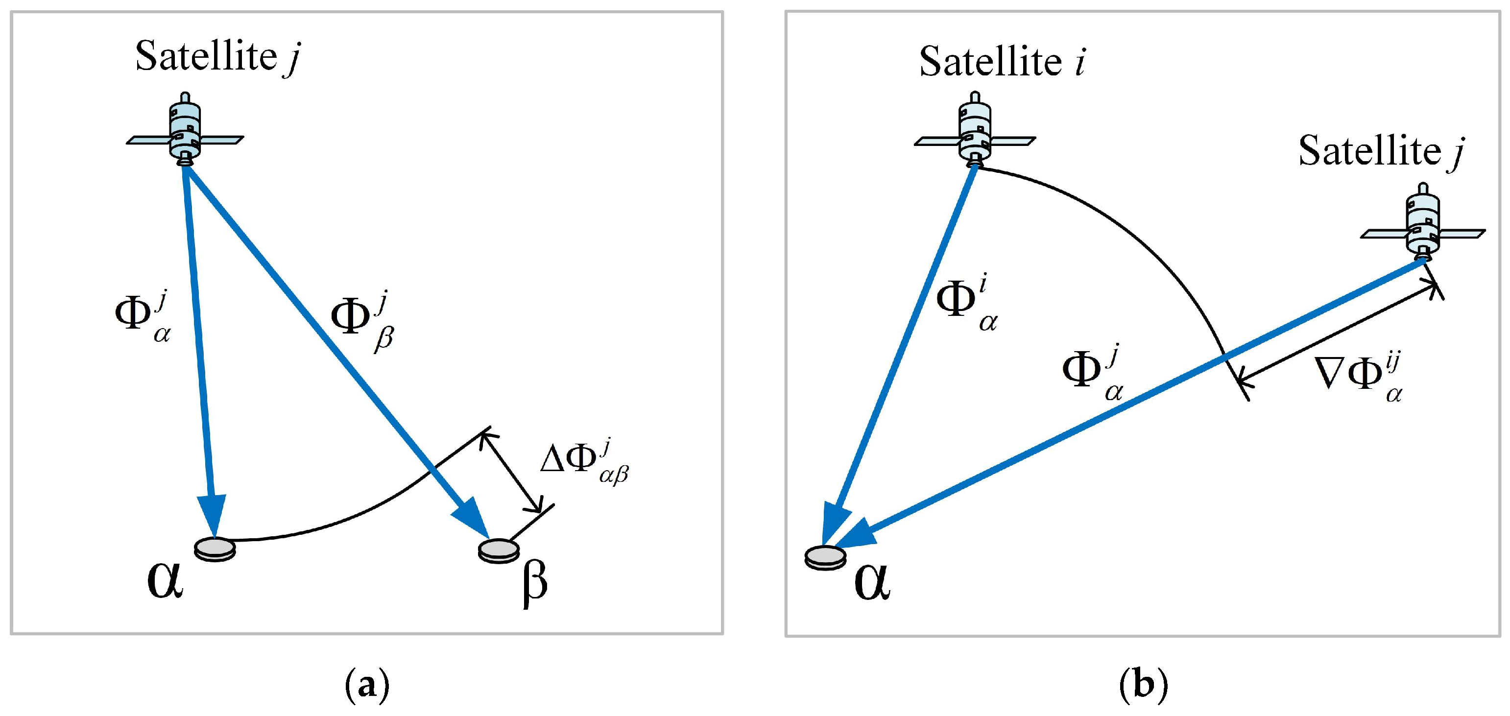
Figure 2.
Interferometric method for measuring phase differences: (a) the first differences are “receiver-receiver”, (b) the double differences are “receiver-receiver-satellite-satellite”.
Figure 2.
Interferometric method for measuring phase differences: (a) the first differences are “receiver-receiver”, (b) the double differences are “receiver-receiver-satellite-satellite”.
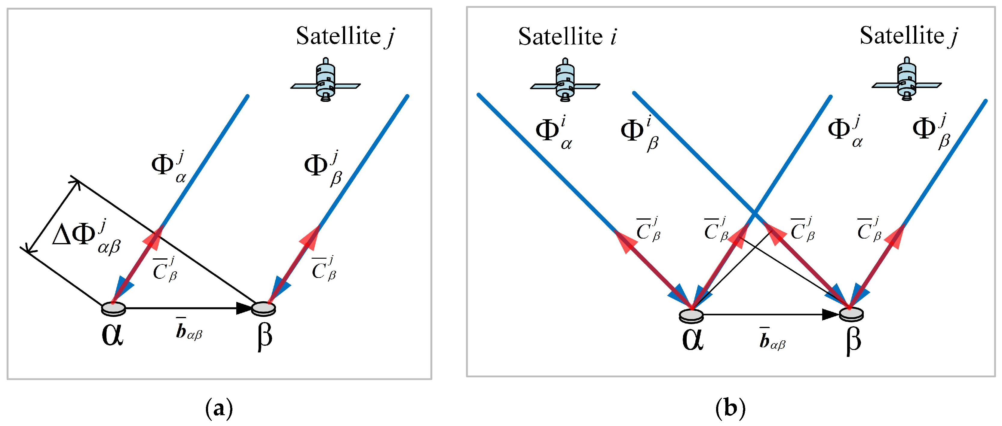
Figure 3.
A block diagram of an algorithm for detecting GNSS spoofing in inertial satellite navigation systems.
Figure 3.
A block diagram of an algorithm for detecting GNSS spoofing in inertial satellite navigation systems.

Figure 4.
The configuration of the GPS constellation and the location of the pseudolites generating spoofing signals.
Figure 4.
The configuration of the GPS constellation and the location of the pseudolites generating spoofing signals.
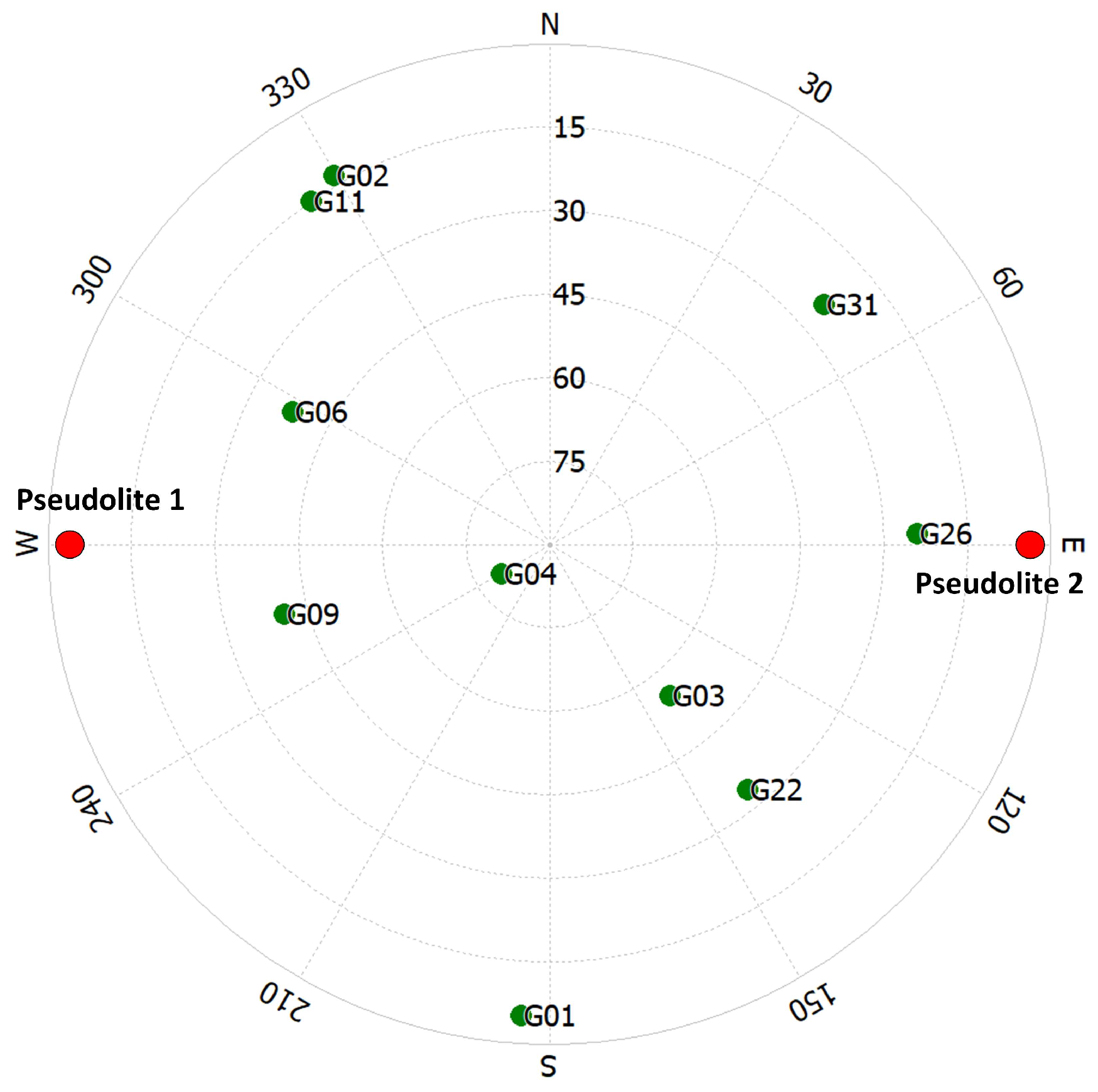
Figure 5.
The difference between the predicted value of the range double difference according to the SINS readings and its value measured using the GNSS carrier phase, obtained with the phase measurement noise of 0.002 m.
Figure 5.
The difference between the predicted value of the range double difference according to the SINS readings and its value measured using the GNSS carrier phase, obtained with the phase measurement noise of 0.002 m.
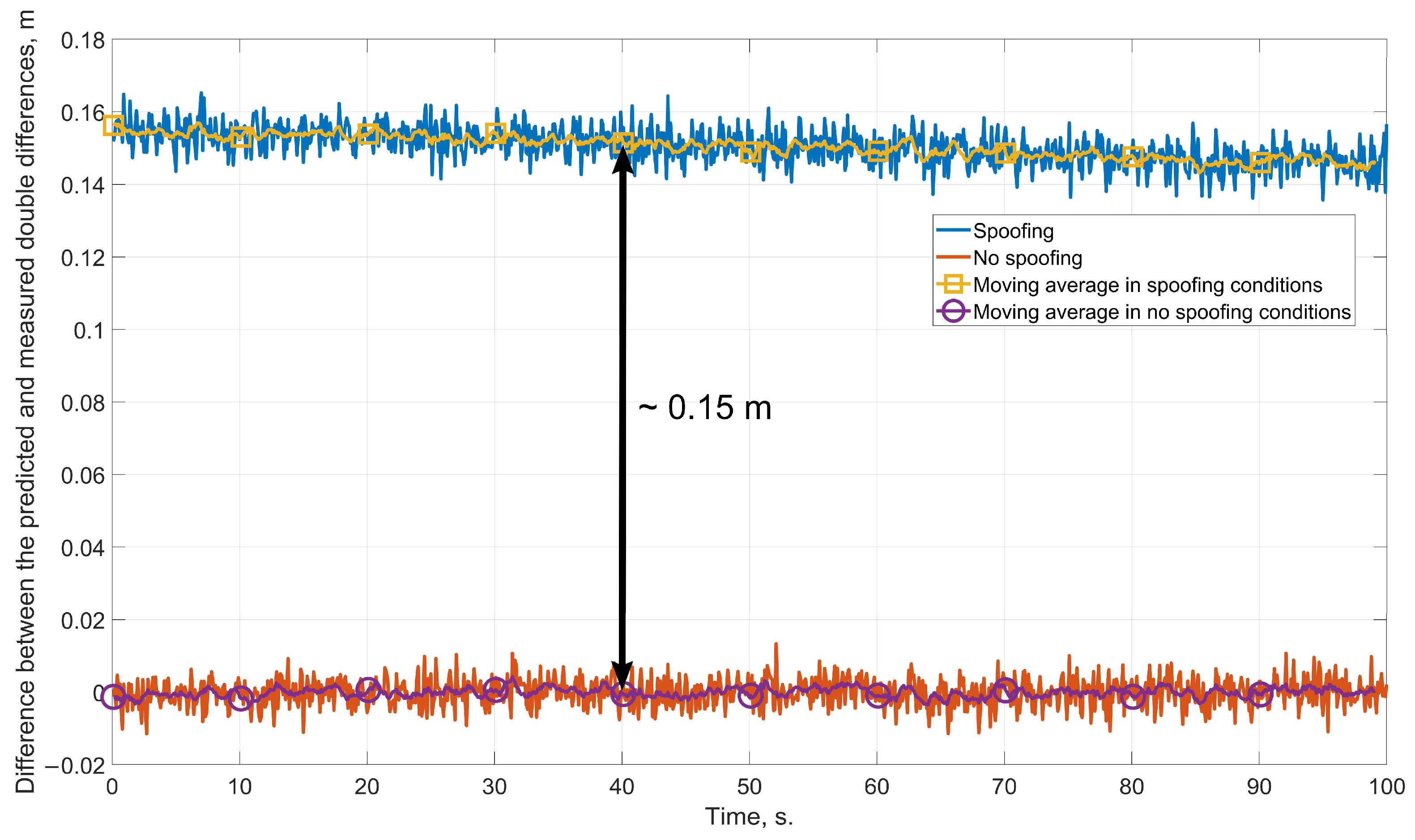
Figure 6.
The difference between the predicted value of the range double difference according to the SINS readings and its value measured using the GNSS carrier phase, obtained with the phase measurement noise of 0.01 m.
Figure 6.
The difference between the predicted value of the range double difference according to the SINS readings and its value measured using the GNSS carrier phase, obtained with the phase measurement noise of 0.01 m.
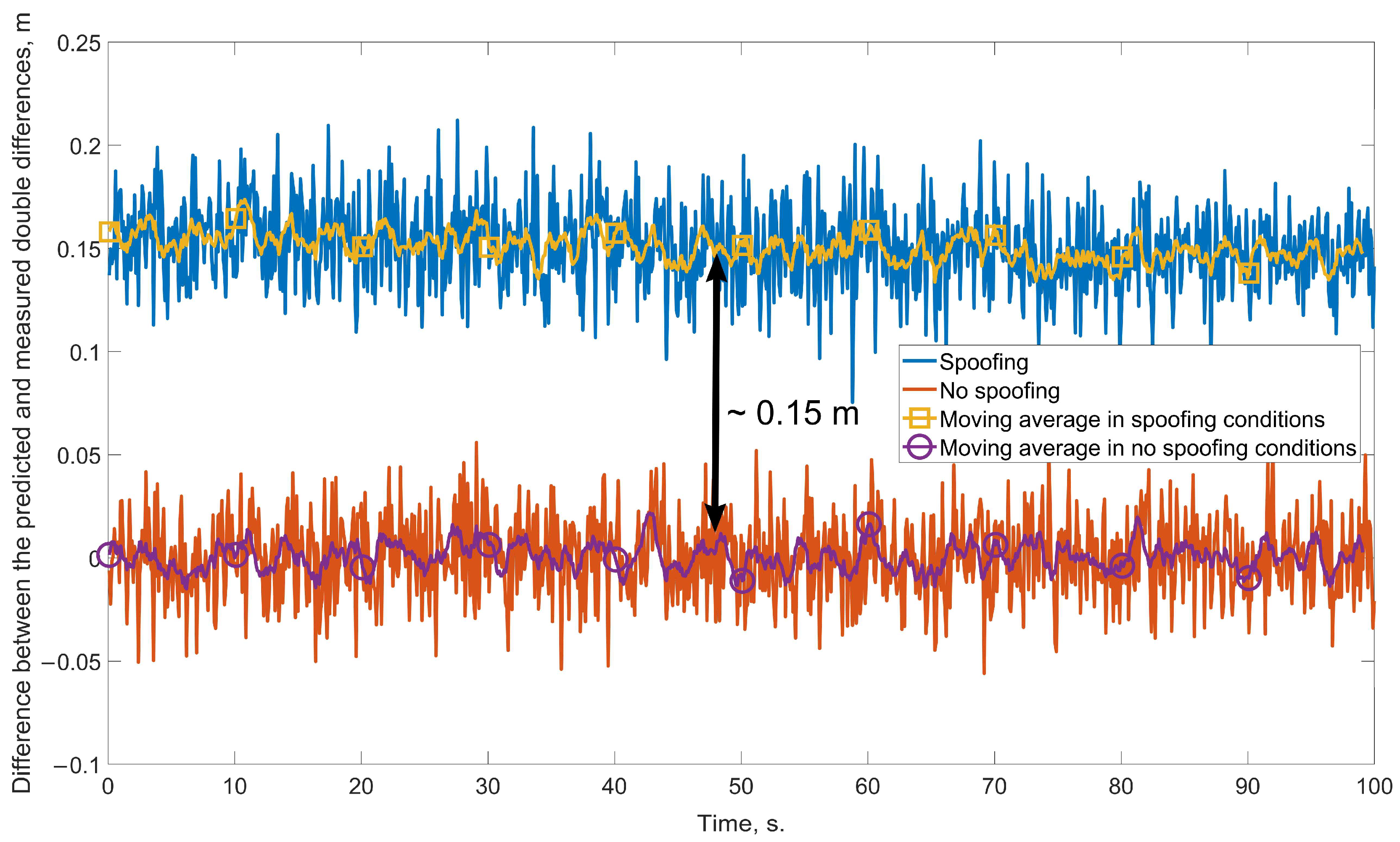
Figure 7.
The difference between the predicted value of the range double difference according to the SINS readings and its value measured using the GNSS carrier phase, obtained at the distance between the antennas of 2 m.
Figure 7.
The difference between the predicted value of the range double difference according to the SINS readings and its value measured using the GNSS carrier phase, obtained at the distance between the antennas of 2 m.
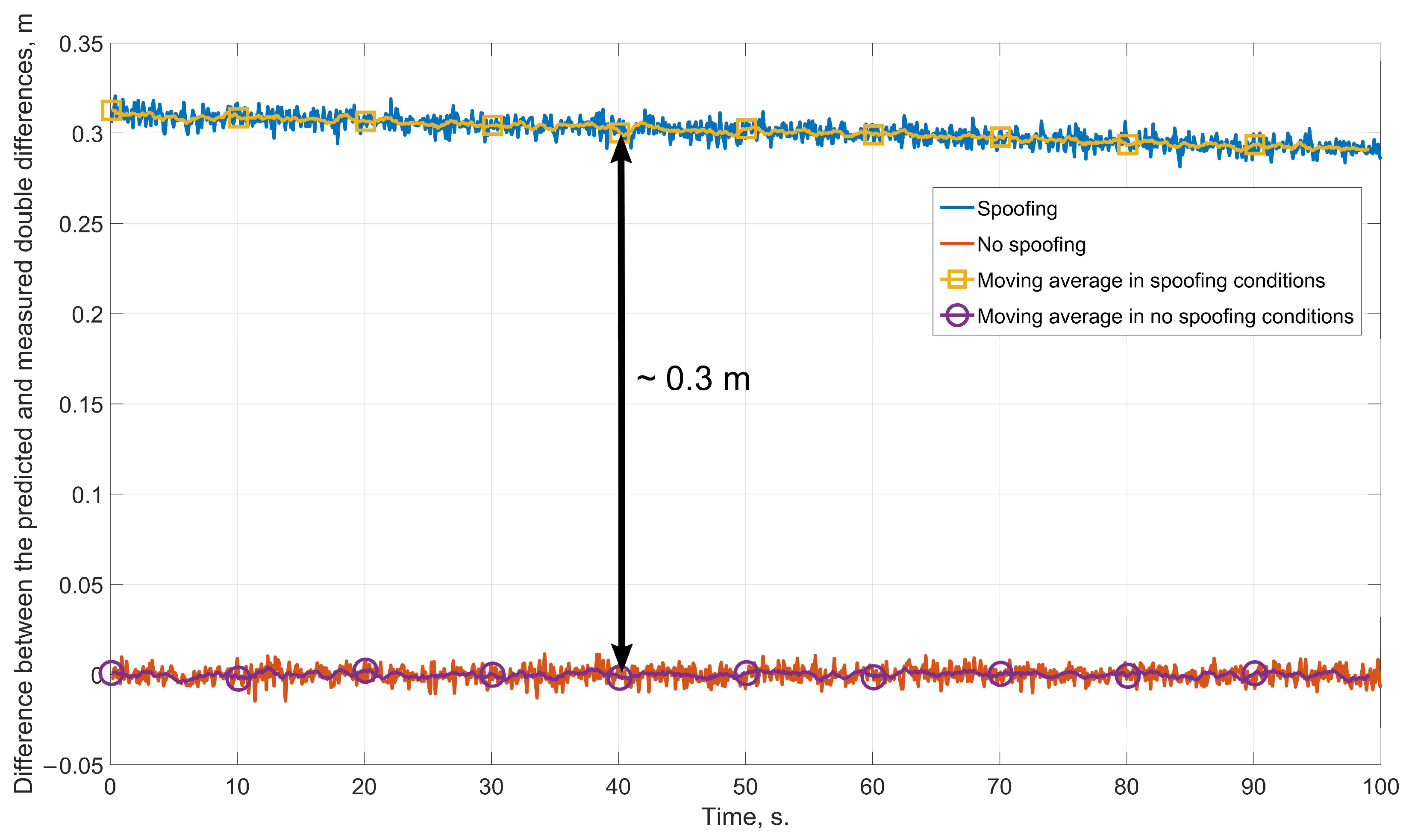
Figure 8.
The difference between the predicted value of the range double difference according to the SINS readings and its value measured using the GNSS carrier phase, obtained at the distance between the antennas of 0.2 m.
Figure 8.
The difference between the predicted value of the range double difference according to the SINS readings and its value measured using the GNSS carrier phase, obtained at the distance between the antennas of 0.2 m.
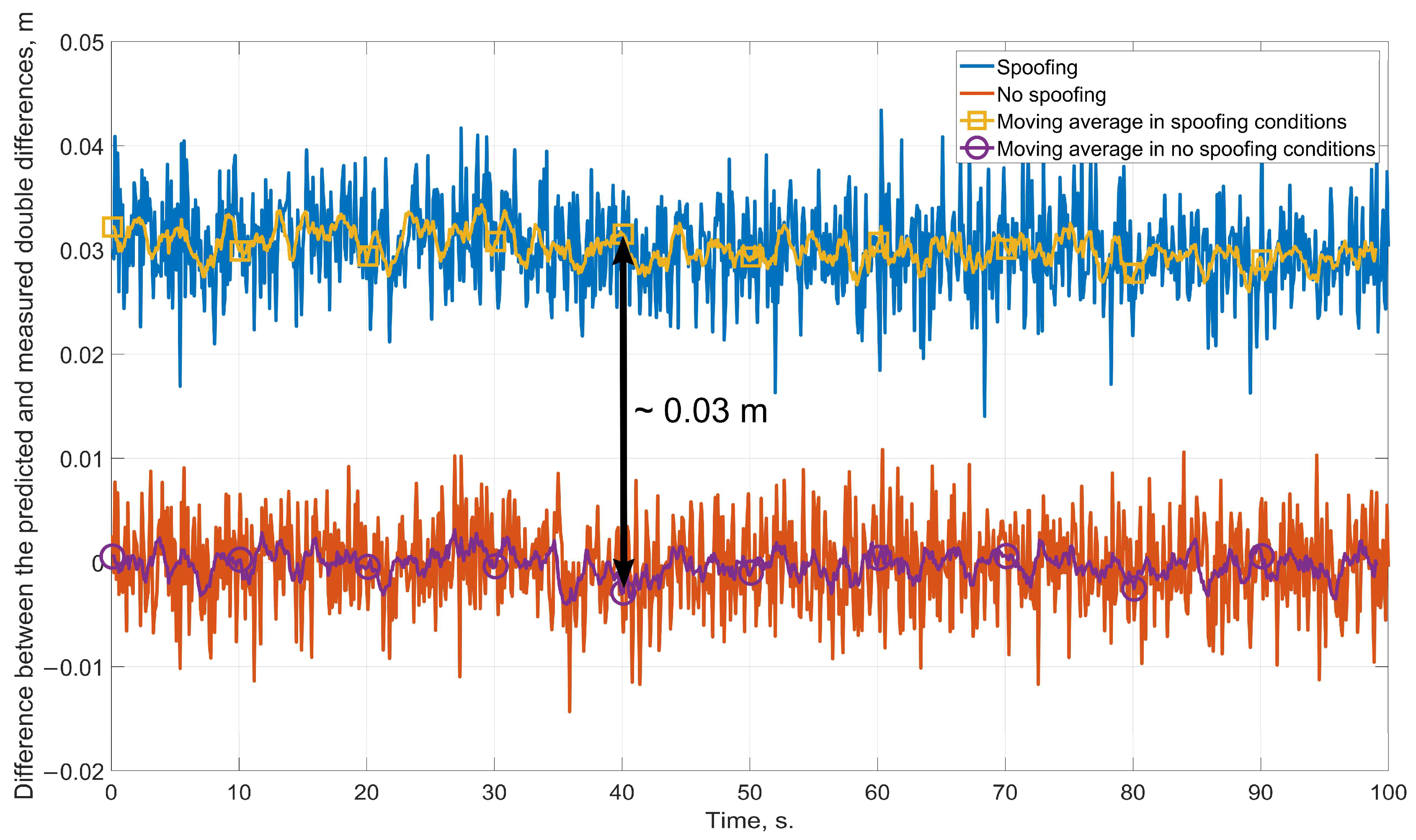
Figure 9.
The difference between the predicted value of the range double difference according to the SINS readings and its value measured using the GNSS carrier phase, obtained using the navigation grade SINS.
Figure 9.
The difference between the predicted value of the range double difference according to the SINS readings and its value measured using the GNSS carrier phase, obtained using the navigation grade SINS.
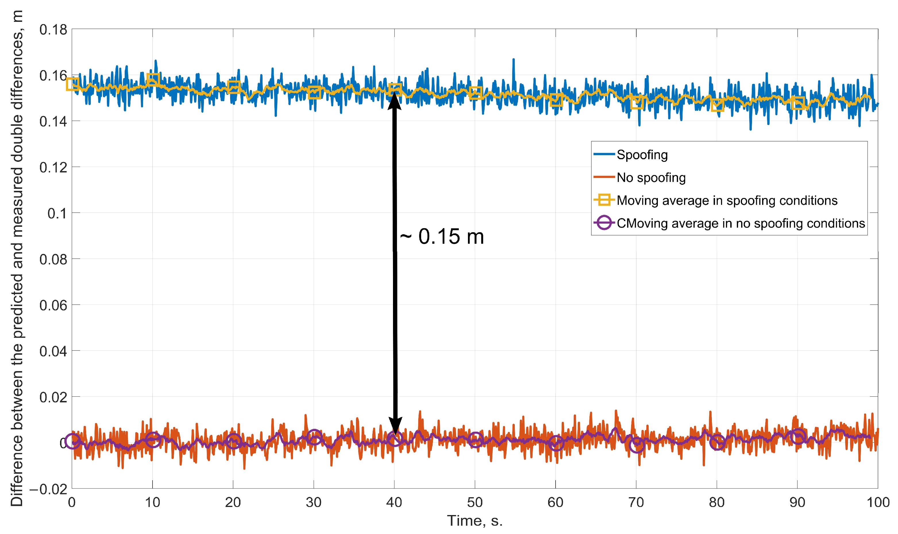
Figure 10.
The difference between the predicted value of the range double difference according to the SINS readings and its value measured using the GNSS carrier phase, obtained using low-grade SINS.
Figure 10.
The difference between the predicted value of the range double difference according to the SINS readings and its value measured using the GNSS carrier phase, obtained using low-grade SINS.
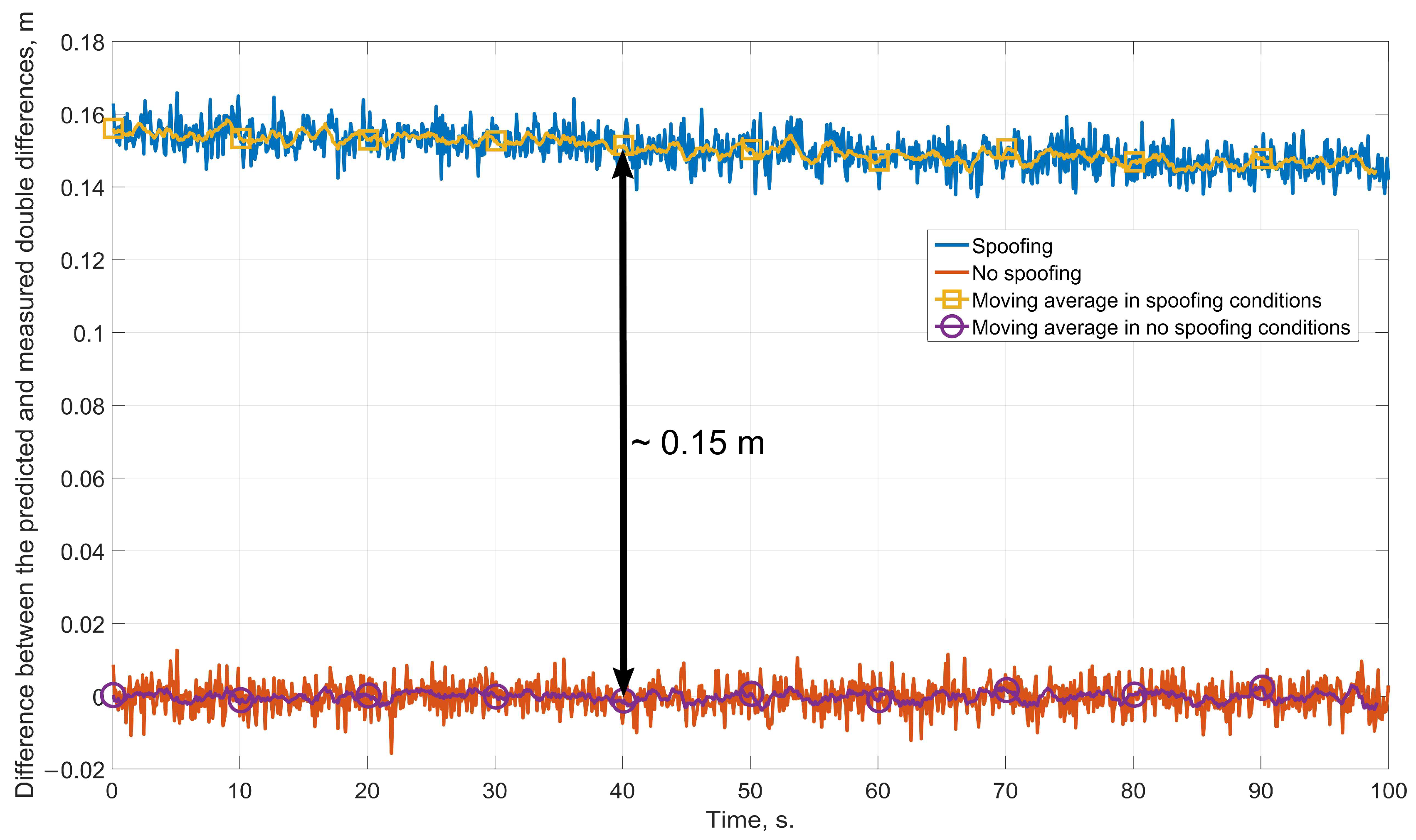
Figure 11.
MAI small-sized integrated navigation system.
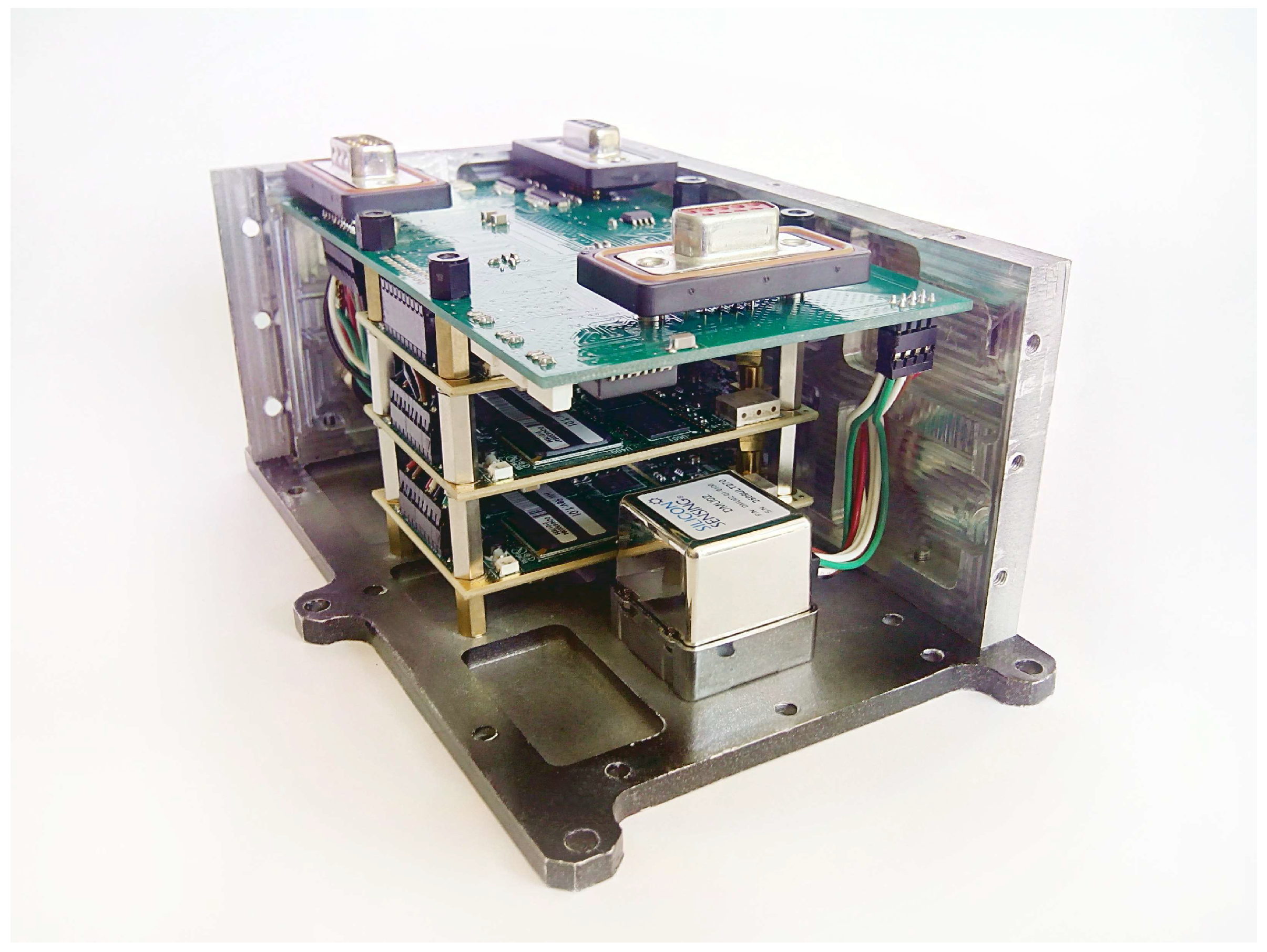
Figure 12.
HIL simulation scheme.
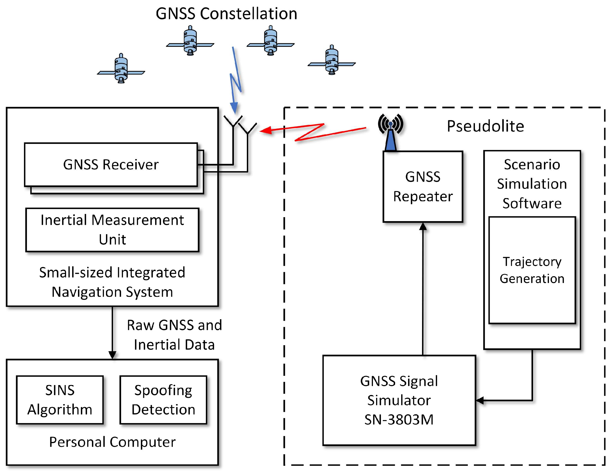
Figure 13.
GNSS signal simulator Navis SN-3803M.
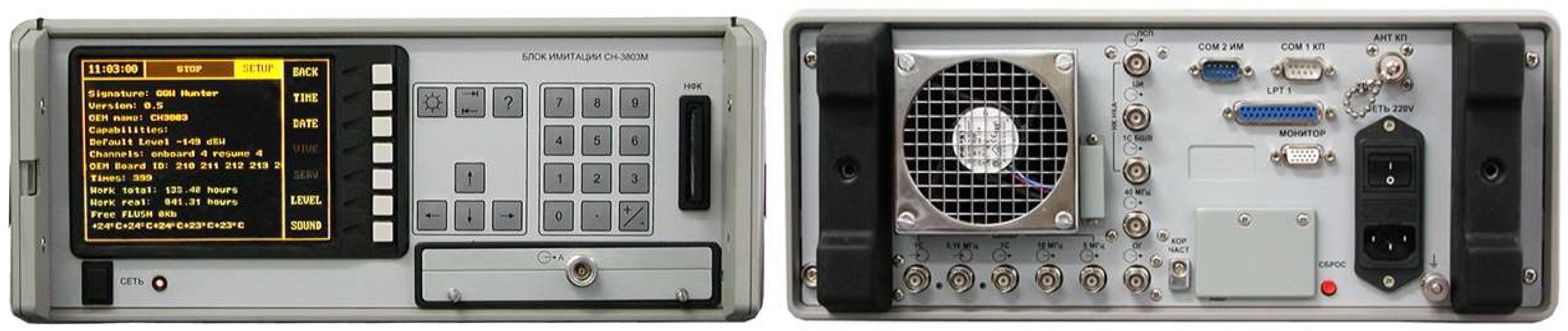
Figure 14.
GNSS constellation.
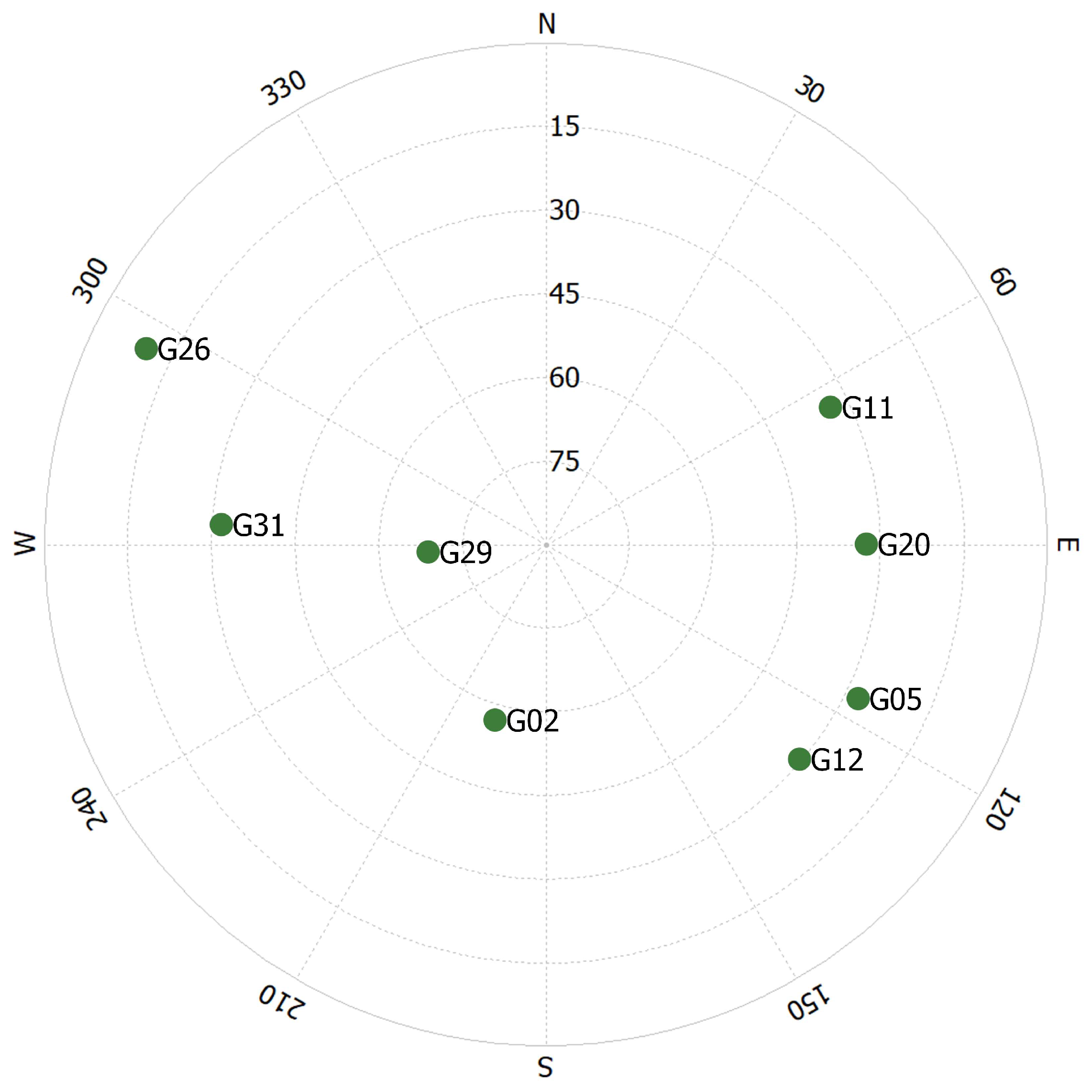
Figure 15.
GPS constellation phase measurement double differences.
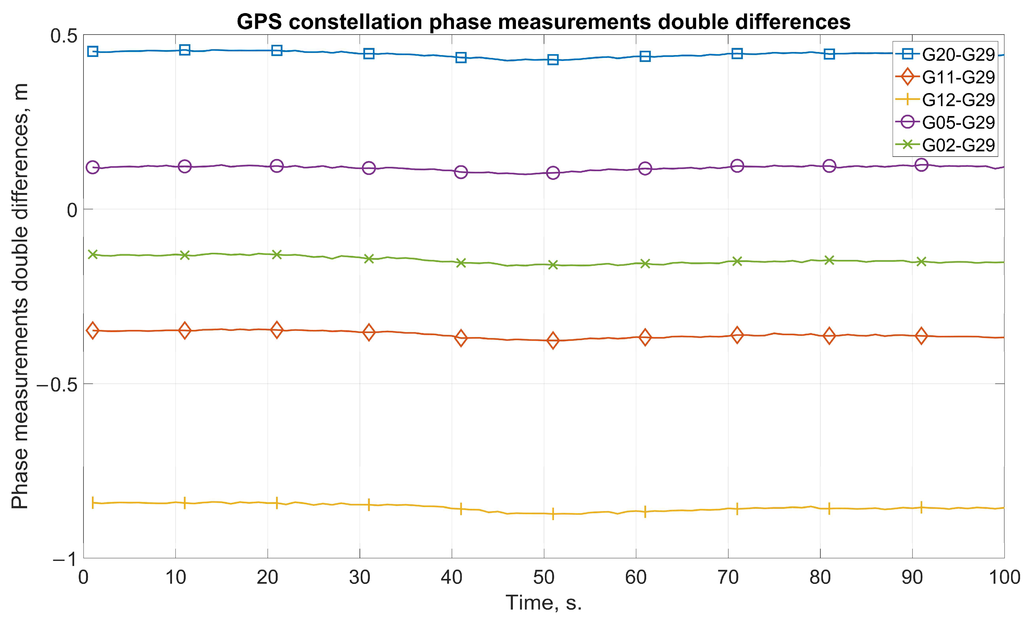
Figure 16.
Pseudolite phase measurement double differences.
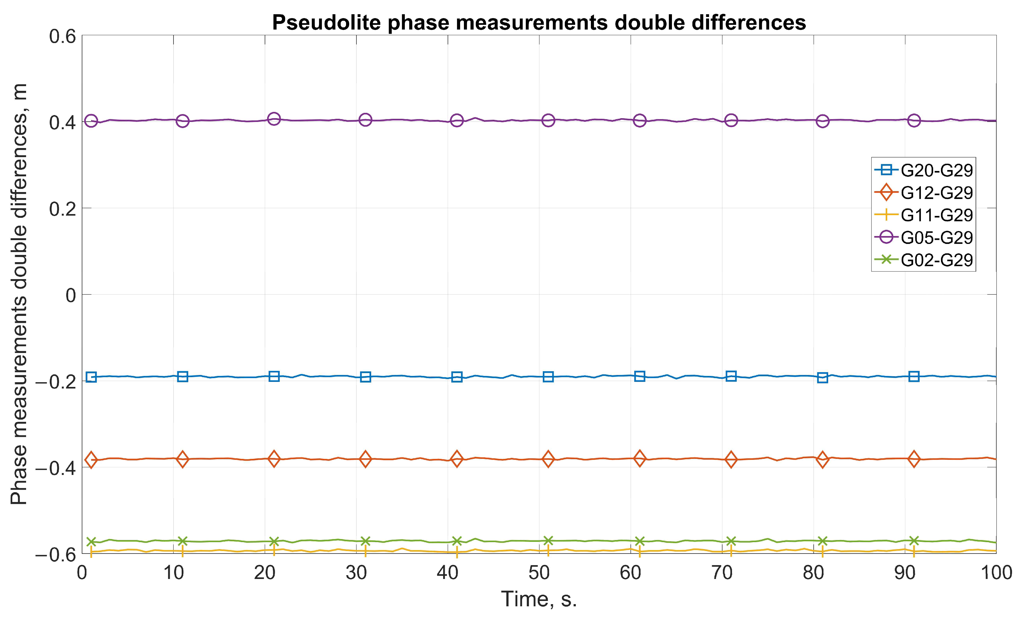
Figure 17.
SINS-predicted double differences and double differences measured by pseudolite signals for satellite pairs (a) G20-G29; (b) G11-G29; (c) G12-G29; (d) G05-G29; (e) G02-G29.
Figure 17.
SINS-predicted double differences and double differences measured by pseudolite signals for satellite pairs (a) G20-G29; (b) G11-G29; (c) G12-G29; (d) G05-G29; (e) G02-G29.

Table 1.
HIL simulation results.
| Sats | Pseudolite DD 1, m | SINS Predicted DD, m | RESIDUAL, m | Time to Spoofing Detection, Epochs |
|---|---|---|---|---|
| G20-G29 | −0.19 | 0.45 | 0.64 | 4 |
| G12-G29 | −0.38 | −0.85 | 0.47 | 3 |
| G11-G29 | −0.59 | −0.36 | 0.23 | 3 |
| G05-G29 | 0.4 | 0.12 | 0.28 | 5 |
| G02-G29 | −0.57 | −0.15 | 0.42 | 3 |
1 DD—double difference.
Disclaimer/Publisher’s Note: The statements, opinions and data contained in all publications are solely those of the individual author(s) and contributor(s) and not of MDPI and/or the editor(s). MDPI and/or the editor(s) disclaim responsibility for any injury to people or property resulting from any ideas, methods, instructions or products referred to in the content. |
© 2023 by the authors. Licensee MDPI, Basel, Switzerland. This article is an open access article distributed under the terms and conditions of the Creative Commons Attribution (CC BY) license (https://creativecommons.org/licenses/by/4.0/).
Share and Cite
MDPI and ACS Style
Zharkov, M.; Veremeenko, K.; Kuznetsov, I.; Pronkin, A. Global Navigation Satellite System Spoofing Detection in Inertial Satellite Navigation Systems. Inventions 2023, 8, 158. https://doi.org/10.3390/inventions8060158
AMA Style
Zharkov M, Veremeenko K, Kuznetsov I, Pronkin A. Global Navigation Satellite System Spoofing Detection in Inertial Satellite Navigation Systems. Inventions. 2023; 8(6):158. https://doi.org/10.3390/inventions8060158
Chicago/Turabian StyleZharkov, Maksim, Konstantin Veremeenko, Ivan Kuznetsov, and Andrei Pronkin. 2023. "Global Navigation Satellite System Spoofing Detection in Inertial Satellite Navigation Systems" Inventions 8, no. 6: 158. https://doi.org/10.3390/inventions8060158