Design of Post-Consumer Modification of Standard Solar Modules to Form Large-Area Building-Integrated Photovoltaic Roof Slates


1
Department of Electrical & Computer Engineering, Michigan Technological University, Houghton, MI 49931-1295, USA
2
Department of Materials Science & Engineering, Michigan Technological University, Houghton, MI 49931-1295, USA
3
Department of Electronics and Nanoengineering, School of Electrical Engineering, Aalto University, 02150 Espoo, Finland
4
Keweenaw Research Center, Calumet, MI 49913, USA
*
Author to whom correspondence should be addressed.
Designs 2017, 1(2), 9; https://doi.org/10.3390/designs1020009
Submission received: 11 October 2017
/
Revised: 13 November 2017
/
Accepted: 14 November 2017
/
Published: 17 November 2017
Abstract
:Building-integrated photovoltaic (BIPV) systems have improved aesthetics but generally cost far more than conventional PV systems because of small manufacturing scale. Thus, in the short and medium term, there is a need for a BIPV mounting system that utilizes conventional modules. Such a design is provided here with a novel modification of conventional photovoltaic (PV) modules to allow them to act as BIPV roofing slates. The open-source designs for the mechanical components necessary to provide the post-consumer conversion for a conventional PV module are provided, and prototypes are fabricated and installed on a mock roof system along with control modules mounted conventionally. The approximately U.S.$22/module BIPV roof-mounted system is direct mounted on the roof to eliminate the need for roofing shingles or other coverings, which effectively provides a 20% total cost reduction from conventional racking systems that demand a roof to mount upon without considering the savings from the rack itself. The results of the outdoor system testing found no water leaks. An increased operating temperature was observed, which would reduce the output from a silicon-based PV module by less than 10%. The results found significant potential for this design to further reduce total PV systems costs.

1. Introduction
With the spot price of solar photovoltaic (PV) modules dropping well under US $0.50/W [1,2], not only has the levelized cost of electricity from solar-generated electricity dropped to 6 cents/kWh [3], even at the residential scale it is less costly than residential electricity prices from the grid in much of the US [4]. The PV industry has continued to succeed in driving cost reductions [1,4,5,6], and new methods of solar financing have become available (e.g., Sunrun, Solar City now Tesla, etc.), which has increased access to PV systems for residential home owners [7,8,9,10,11,12]. Due in part to the potential for profitable residential solar installations and widespread popular support for renewable energy technologies like solar PV [13], the demand for PV has grown substantially, where the US PV market installed 14,762 MWdc of solar PV in 2016—nearly doubling the capacity installed in 2015 [14].
However, with the learning curve of PV [15,16,17,18] driving down module costs ($/W), the economic role of other balance of systems (BOS) components has gained prominence (e.g., racking) and can even dominate the economics of a PV system [6]. Historically, the academic interest in PV racking has been low, with only two studies being published (2015 and 2016) in the non-patent literature as of this writing (on flat roof racking) [19] and racking for the developing world [20]. Due in a large part to this lack of attention and the relative unimportance of the costs of PV racking, it has been marginal historically, and there has been little progress on reducing the materials and costs associated with PV racking [1].
A typical residential roof rack comes in many different styles depending on roof type (shingles, metal, tile, etc.), but they all have similar traits. Currently, all of the rooftop PV mounting systems used for conventional modules have some sort of standoff, which will increase the distance between the roof and the PV modules from inches to feet depending on roof slope. The standoff has been historically included in order to dissipate the thermal energy in the modules in an effort to minimize efficiency loss from higher operating temperatures for the PV. There are many racking options for different appearances and angles for optimal settings, and their costs are now relatively high compared to reduced module costs. For example, the Rooftrac racking system costs $0.12/W for a residential application [21]. Such inflated racking costs results in lower returns on investment and higher upfront costs for PV systems, which can deter homeowners from adopting the technology. In addition to the exorbitant cost, some people find an aluminum extruded offset roof rack aesthetically unappealing (e.g., home owners associations have in extreme cases banned PV [22]), and such systems always demand the full cost of a standard roof underneath them, as the PV offer no actual roofing services.
The PV industry has responded to this aesthetic challenge with a growing number of building-integrated photovoltaic (BIPV) systems, with products such as PV roof slate [23] and PV roof shingles [24]. These BIPV products that have improved aesthetics generally cost far more than conventional PV systems [25,26,27,28]. These more intelligent BIPV systems cost more than conventional large area glass-framed modules primarily because of their relatively small scale that cannot take advantage of the economies of scale observed in the standard module market. Thus, in the short and medium term, until BIPV reach the scale of conventional modules, there is a need for a design of a BIPV mounting system that can utilize conventional modules.
In order to provide such a design to overcome these challenges, this study investigates a novel modification of conventional PV modules to allow them to act as BIPV roofing slates. The open-source designs for the mechanical components necessary to provide the post-consumer conversion for a conventional PV module are provided, and prototypes are fabricated and installed on a mock roof system along with control modules mounted conventionally on a manual tilt ground-mount system. In addition, as the BIPV roof-mounted system is directly mounted on the roof, it eliminates the need for roofing shingles or other coverings. The systems is monitored for water leaks as a roofing material as well as for temperature to quantify any expected effects on the PV performance. The technical limitations and economic viability of this novel BIPV system design is compared to BIPV racking systems already available on the market. The results are presented, and conclusions are drawn about the potential for module modifications for BIPV to further reduce total PV systems costs at the residential level.
2. Materials and Methods
2.1. PV Module Design Modification
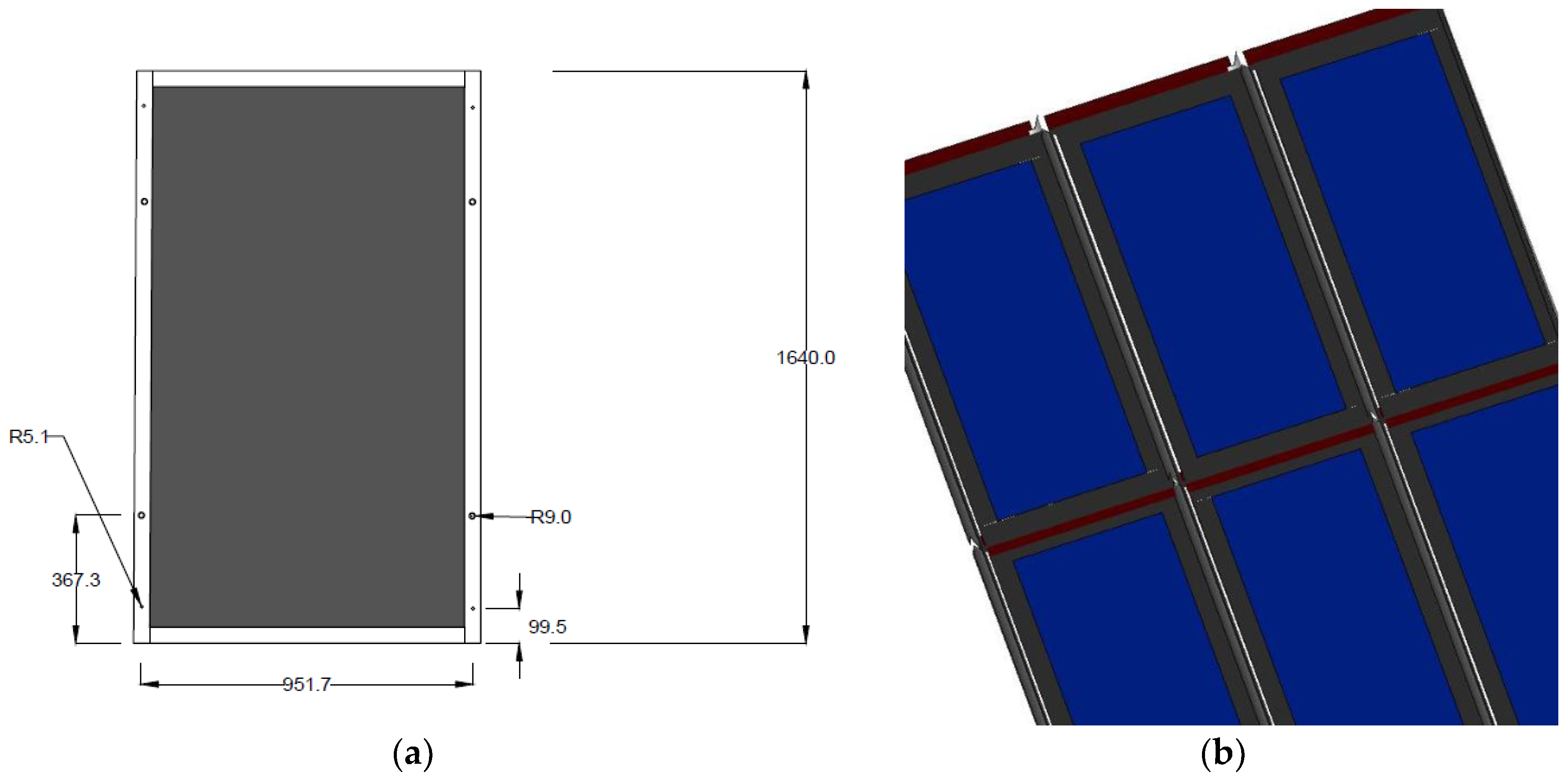
Table 1 shows the bill of materials (BOM) with sources and approximate costs for the components on a cost per unit and cost per module basis. The PV modules used are 1640 mm by 951.7 mm or 1.56 m2.
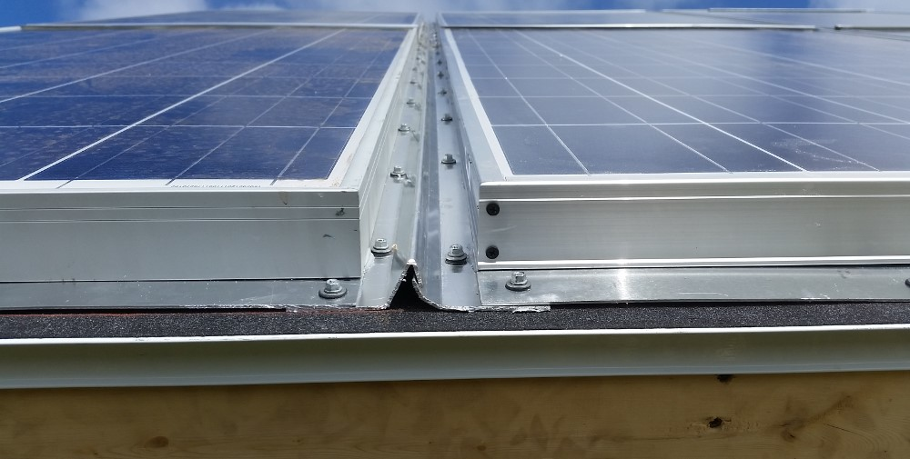
The design of the components for PV module modifications are shown in Figure 1, Figure 2, Figure 3 and Figure 4. The designs were developed in AutoCAD and are available as fully open source hardware [33] at the Open Science Framework [34]. Figure 1 shows the bottom z lip in top view (a) and side view (b). The bottom components is in reference to the bottom of the module and the z lip goes from the back of the top module over the front of the next row of modules further down a roof.
The top mount is simply a straight component with holes cut in it to mount to the back of the top of a module, as shown in Figure 2.
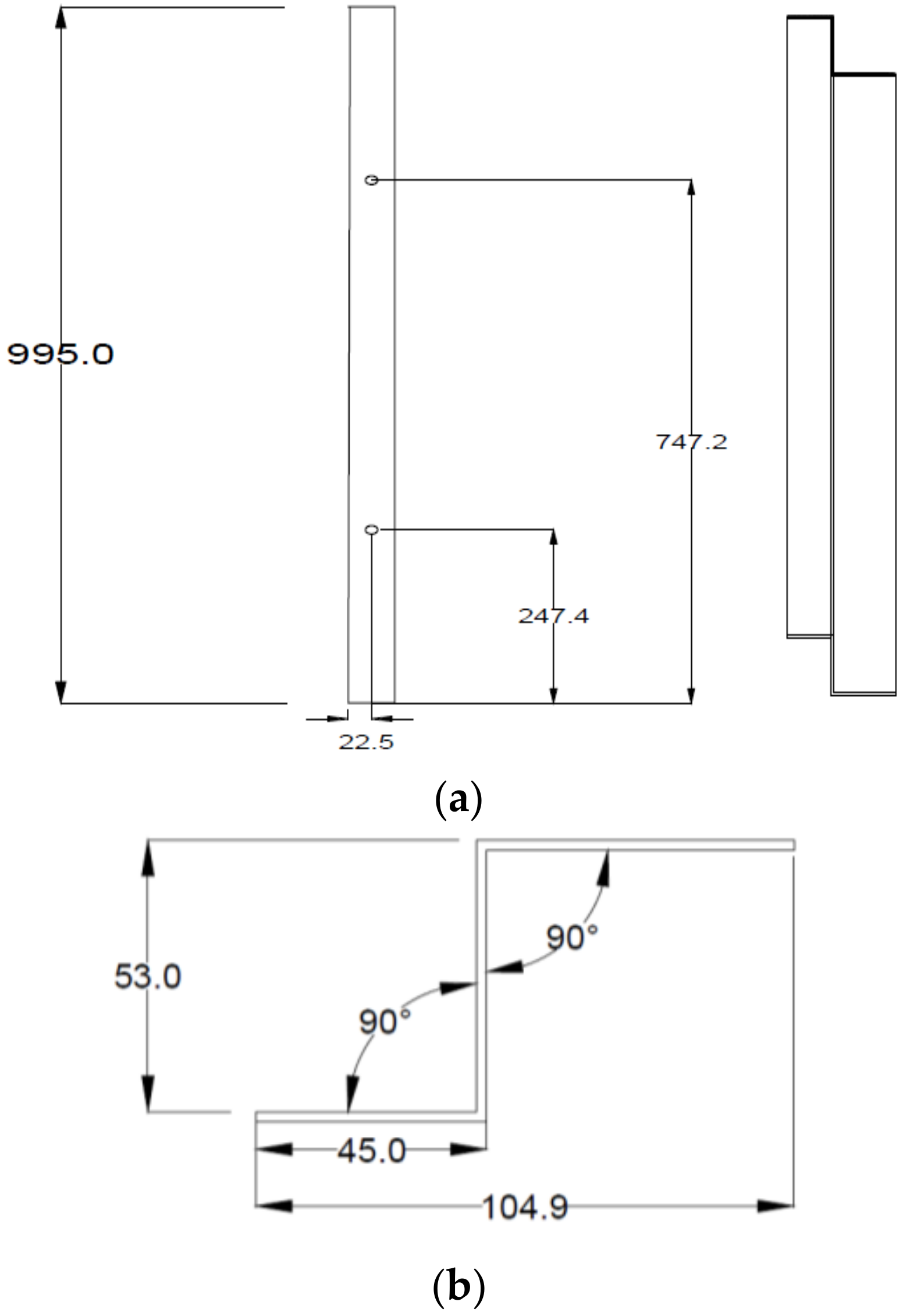
Figure 3 shows the left solar module mount, which has a v-shape bend in the aluminum to form a water proof channel over the right mount that is shown in Figure 4. Figure 4b shows the 120° bend that helps form the vertical channel.
To adapt the designs shown in Figure 1, Figure 2, Figure 3 and Figure 4 to another type of PV module, in general, the lengths would need to be resized to fit the new module, and holes will need to be placed in the corresponding holes in the frame of the new module. The depth of the z step is set by the depth of the module frame, and the overlaps and widths of the pieces can be adjusted for aesthetics and the varying offsets between the edge of the module and the active PV region.
2.2. Assembly and Installation
The four aluminum pieces (Figure 1, Figure 2, Figure 3 and Figure 4) are sealed using the polyurethane sealant on all four sides of the PV module (example shown in Figure 5) and fortified with metal fasteners (as shown in Figure 6). It is important that the sealant forms a continuous bead all along each edge of the PV module to avoid water penetration between the aluminum of the additional component and the frame of the module. Thus, the four aluminum components (Figure 1, Figure 2, Figure 3 and Figure 4) and the PV module (Figure 5) form a single waterproof slate, which can interlock with others to form a 2D array. In this study, multicrystalline silicon-based PV modules were used, but the system design will accommodate any form of square or rectangular standard PV module with a frame. The additional aluminum components would need to be resized appropriately, keeping the same fundamental geometry, and holes would need to be cut to accommodate those of the new module.
The roof is prepared following the protocol for fabricating a conventional rooftop by first installing felt roof deck protection. The bottom row of PV modules is the first PV installed using neoprene-gasketed screws with the lip of the module on the left overlapping the curl of the module on the right—creating a rainproof channel between the modules as shown in Figure 7 and detail in Figure 8. Roughly, a dozen screws are driven through the aluminum and moisture barrier into the wood underlay of the standard roof on each side of the slate. The bottom row of the modules has a flat aluminum component rather than the Z bracket and is also held in place by six additional screws. There are thus about 30 roofing screws per module holding it to the roof.
For the installation of the next rows of PV modules, the Z-shaped aluminum bracket from the upper module overlaps the non-active part of the PV module frame as shown in Figure 7.
Additional rows of PV modules are installed until the roof is completely covered. Finally, a bent channel of aluminum is installed over the top row of PV modules as shown in Figure 9. This can also be done in overlapping sections of aluminum channel depending on the width of the roof.
2.3. Experimental
A three columns by two row experimental BIPV system (Figure 10) was installed on a fabricated roof structure mounted on a variable tilt angle array at the Keweenaw Research Center (KRC) outdoor PV testing site. The test site is at 47.17° N latitude, 88.49° W longitude, and at an elevation of 1095 feet (334 m). To quantify the impact on the operating temperature of the PV, two temperature sensors were located on the BIPV array. The first temperature sensor was placed beneath the center of a module on the BIPV array and second one more near the frame of another module in the BIPV array and taped and zip tied in place. Finally, one additional temperature sensor was mounted in the middle of an identical module installed conventionally on a tilted rack at the same tilt angle. This third temperature sensor thus acted as a control for the normal operating temperatures for modules installed in ground-mounted conventional racks (i.e., fully passively cooled on both sides of the module). The moisture sensor was inserted into a sponge and mounted in order to soak up any water that is present beneath the module on the BIPV system and then produced a voltage corresponding to that amount of moisture. For the experiments described in this study, the tilt was fixed at 45° for the experimental roof and the control system.
2.4. BIPV System Testing
In order to test the BIPV setup, an Arduino Uno and AdaFruit Data Logger Shield, along with temperature (TMP36 analog temperature sensor) and moisture sensors, were used to continuously take data every 15 min over the course of 1.5 years. KRC data at 2 m of elevation is used for quantifying the liquid precipitation per day, average daily ambient temperature, and peak daily wind speed [35,36,37], as this is approximately the height of the simulated roof. Following open-source lab principles [38,39], an open-source monitoring system was designed using those core components. The open-source monitoring and data logging system sourced from Adafruit [40], although some supplies were sourced from lab supplies (e.g., wire connectors and part of a sponge for the moisture sensor).
The electronic schematic of the open source monitoring and data logging system is shown in Figure 11, and the open-source software is available [41]. Figure 11 shows an open-source Arduino Uno microcontroller pin layout and how to wire the three temperature sensors and the moisture sensor to it in order to use the free software available in [41].
Due to the design of the BIPV system, these modules are not open to air flow on the back of the modules, as in a conventional rooftop mounted PV array. The Arduino system takes three temperature measurements and one moisture measurement for the roof system. The last temperature is logged from underneath a control panel on the control rack. The circuit is setup making use of four analog pins on the Arduino Uno, which then uses the Data Logger Shield to write the data directly to an SD card in a comma separated values (CSV) file.
3. Results
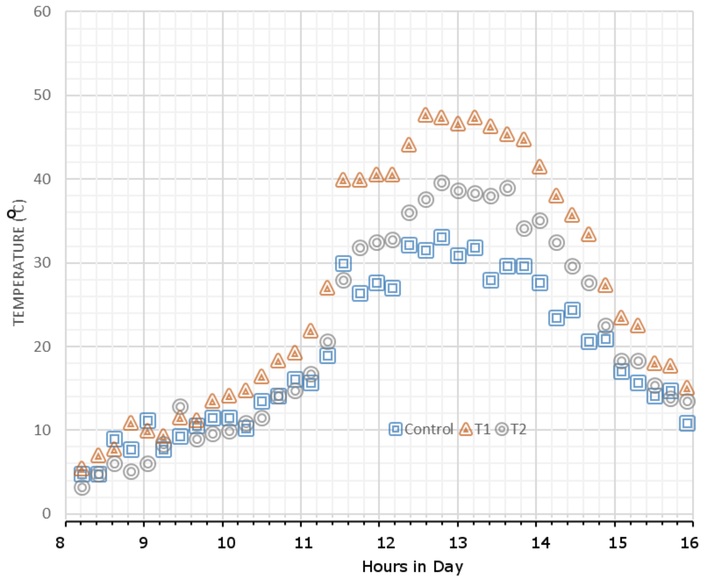
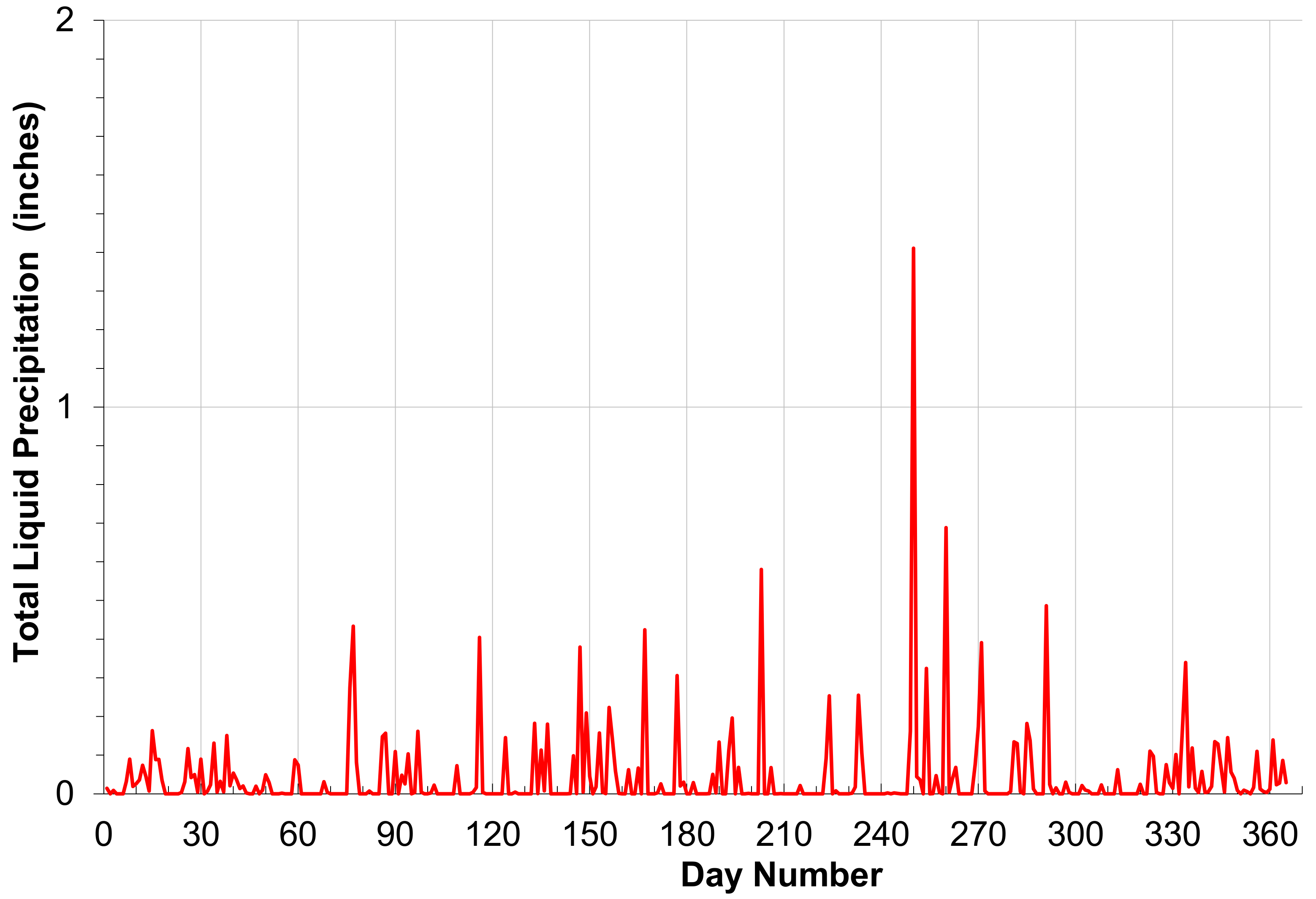
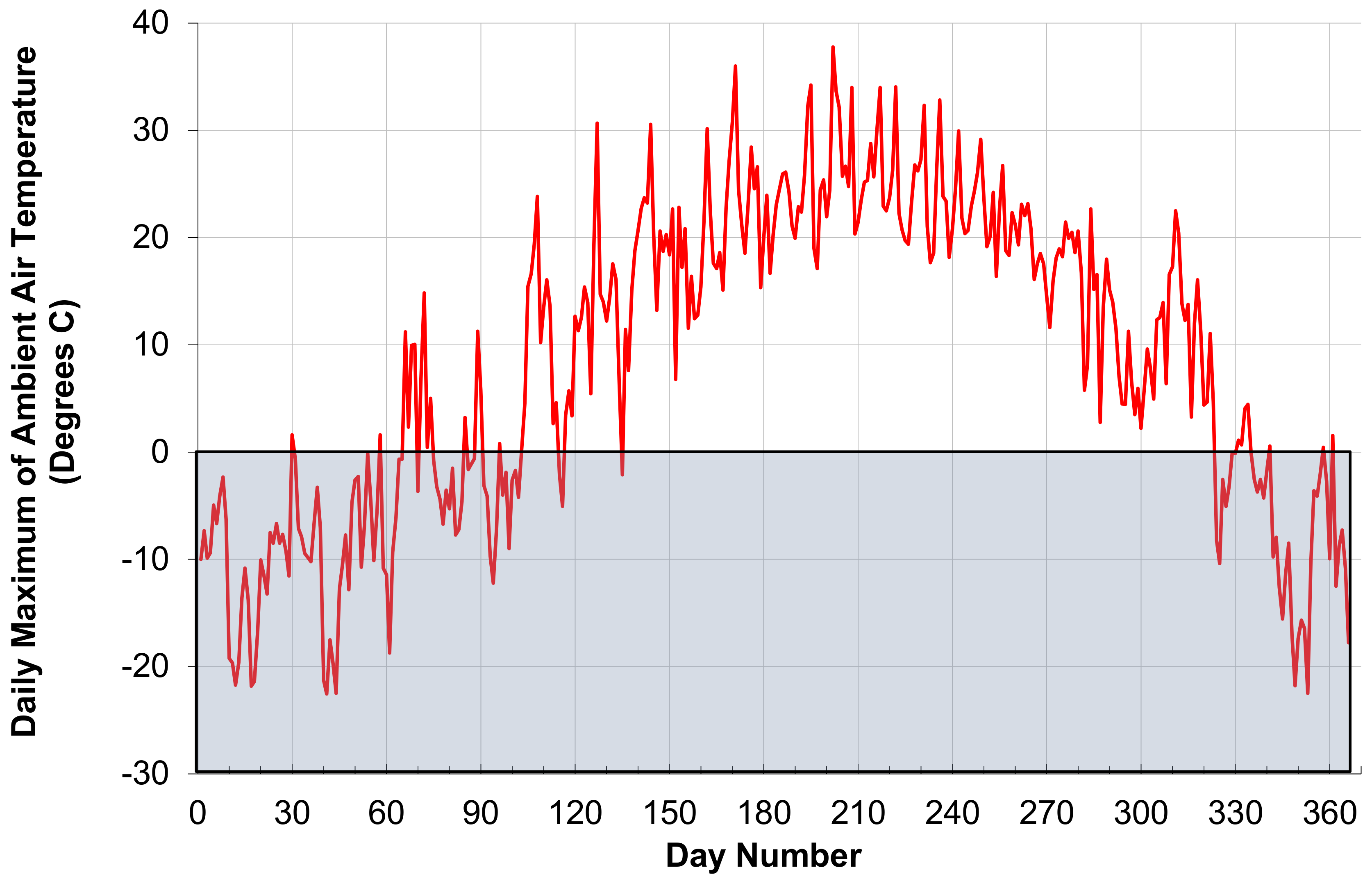
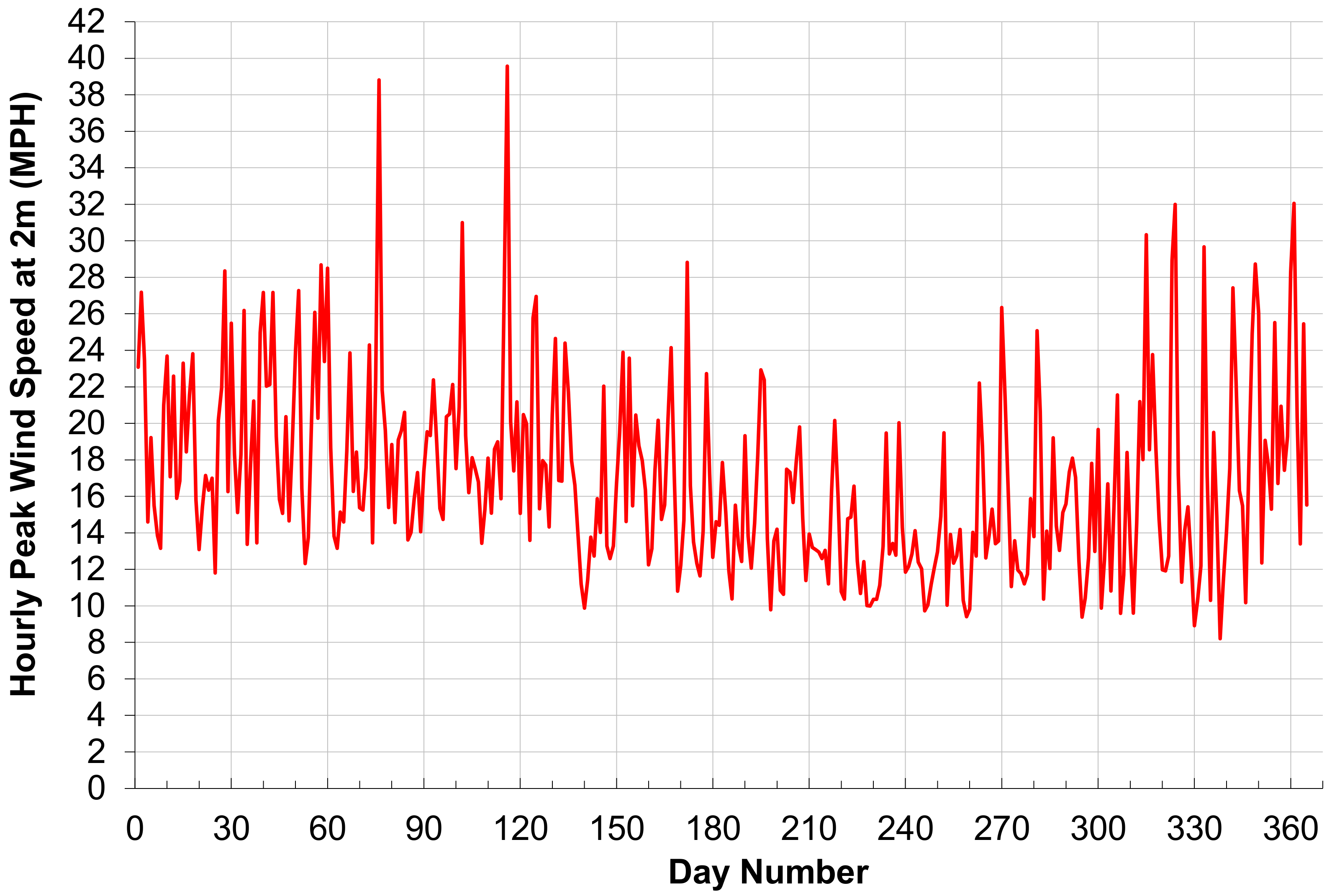
There are two major concerns for the design of the BIPV system described here: water tightness and unacceptable temperature increases. Both of these concerns were studied here in order to provide a full proof of concept. First, there was no moisture sensor data that indicated there was a leak, although the changes in the humidity were detected by the sensor located under the array. This occurred despite the array being exposed to dozens of rain fall events, as shown in Figure 12, which shows the total liquid precipitation per day through a year (2016) and included precipitation over a wide range of temperatures, with roughly one third of the days averaging below freezing, as seen in Figure 13, which shows the maximum absolute air temperature at the test site over the same period. The maximum temperatures would be those that have the largest detrimental effect on PV output at the peak sun and temperatures of the day. In addition, the roof structure was exposed to full outdoor wind conditions, as shown in Figure 14. Figure 14 displays the peak wind speeds in miles per hour (MPH) over the same time period at the elevation of the roof system. It should be noted that because this was a simulated roof structure the vibrations created by the wind would be expected to be greater than a sold roof supported structurally under every point, so the vibrations that the system encountered were greater than those experienced by a normal rooftop PV system in the same location. Despite these extreme conditions, the results indicate the system was able to protect the simulated roof from water over the course of the study. The second concern of an increased temperature in the BIPV array over a control module (with an open back available for cooling) was found to exist. Although the average temperatures for the control and the BIPV system were only a few degrees above the ambient, such small increases in the average are misleading, as they entail a lot of time at night when there is no difference between the module temperature and the ambient. More instructive is the temperature beneath the modules range throughout the day that went from a few degrees to 25° Celsius higher or more than the ambient. This is a well-known phenomenon where the average operating temperature for a PV system is normally taken at 50 °C and STC (standard testing conditions) is 25 °C. However, in the BIPV case, the temperature increases even more, even in modest solar conditions, as is shown in Figure 15, for a sunny day in November. As can be seen in Figure 15, both of the BIPV measurements were higher (6–15 °C higher) than the control module. As shown in Figure 15, there was a significant variance between the temperature measurements for the BIPV system. This is most likely due to the location of the sensor (near or the metal perimeter of the module). This spread was observed throughout the entire data set.
To gauge if such temperature increases are significant, the temperature coefficient of a standard polycrystalline silicon-based photovoltaic modules of −0.45%/°C at 25 °C at AM1.5 (Air Mass 1.5) and an irrandiance of 1000 W/m2 [42] can be used as an example. The resultant reduction in output would take a 15% efficient PV module down to 12.9% for a standard setup. However, for the BIPV design proposed here, the reduction would be to 12.5% and 11.9% for the two BIPV measurements, respectively. This is between a 3% and 8.5% loss in output as compared to a standard racking system. Such losses may be acceptable depending on the economics of the system as this approach eliminates the cost of roofing material. Finally, it should be pointed out that such temperature increases would be expected for any type of BIPV that does not have additional cooling to offset the reduction in back surface airflow.
4. Discussion
The results of this study have shown that a successful open-source design of a post-consumer modification of standard solar modules to form large-area BIPV. Further work is needed to make open source designs for complicated roof structures (ridges, hip, valley, fascia, etc.) The modification uses an approach that could be commercialized by small and medium sized entities (SMEs) as well as DIY (do it yourself) homeowners with access to equipment for bending the aluminum as well as drilling holes. There may also be a future market opportunity to use these designs in a kit form and sell directly with specific PV modules to consumers. Slightly modified designs would be necessary for each geometry of PV module. It should also be pointed out that there is an opportunity for manufacturers to begin making the frames of the PV modules that essentially fit the interlocking slate design proposed here or similar to completely eliminate the additional cost of the modification of a module to a slate.
The promise that this open-source design of a post-consumer modification of standard solar modules to form large-area BIPV needs significant further work to have the full potential realized. First, the impact of the increased temperature of the BIPV system can be run against control modules mounted on conventional roofing for a wide range of PV material types and different temperature coefficients (e.g., crystalline silicon, amorphous silicon, cadmium telluride, copper indium gallium selenide, and other PV module types). For example, the temperature coefficient of amorphous silicon is roughly half that of crystal silicon and thus would provide better relative performance decreases in this application due to increased operating temperature. In addition, the use of PVT (photovoltaic thermal) hybrid systems should also be considered, as the increased temperature would be an asset for driving up the efficiency of the solar thermal side [43] and the overall exergy of the system may increase [44]. This data can be used to guide a full life cycle cost analysis, which can be run in the future comparing the cost of the BIPV system to the replacement of various forms of standard roofing materials with PV mounted conventionally on top as well as the many BIPV products on the market. To complete such a study, detailed measurements on the time to assemble and install would need to be made for both making the conversion as well as installing the systems over a wide array of roof types. This will enable assigning appropriate labor rates to work with such conversions. Next, the cost of the materials would need to be quantified for both standard and other BIPV systems.
For comparison of the material costs, a preliminary price survey performed in the PV industry found only United Solar and Luma Resources prices available in the USD 5–7/W range, which is a notable premium over the costs of standard PV modules (<USD 1/W). BIPV products from Atlantis Energy, CertainTeed, Hanergy Group, Lumenta, Romaq, SunPower, Suntech, and Tesla have developed BIPV slate-like products but were not in a position to provide accessible information for costs to consumers. This is in part due to their sales models (e.g., leases or solar services), but also the products being relatively immature or unavailable commercially as of this writing. However, even this preliminary information indicates this approach could be highly profitable for consumers to do the retrofit themselves or for small companies to perform such retrofits to scale. It should be noted that this is only valid for off-grid stand-alone systems or in jurisdictions that would allow owner modified systems. In other regions, where professional installers are necessary to allow interconnection to the grid, a roof owner would need to use a professional installer to complete the BIPV system. The data provided here is a starting point to encourage such installers to consider BIPV systems based on the designs shown here. With standard silicon based modules of 1.5 m2 being about 250 W (or more) creates about 166 W (or more) per m2. If the price of the lowest cost PV modules available is about 40 Euro cents per W [45] and the conversion rate is 1.17 USD per Euro [46], the cost is USD 0.47/W for PV. The lowest cost conventional PV ($0.47/W) and the cost of the BIPV rack shown here (USD 22/250 W << USD 0.10/W) for a total cost of less than USD 0.60/W. This is roughly a factor of 10 times less expensive than the BIPV on the market with costs available. It should be noted, that this does not include the labor costs to modify conventional modules. However, reducing the costs of the BIPV materials to 10% of the available commercial products provides significant economic flexibility for additional labor costs, whether completed by the roof owner or a professional.
Similarly, these costs can be compared to roofing materials. This would result in a USD 78/m2 cost for the module and USD 22/m2 for the racking for a total of USD 100/m2 (this is USD 9.35/square foot or USD 934 per square). Even at 1 USD/W, the cost of PV module would be USD 250, and with the additional cost of racking being USD 22, the total cost per square m is about USD 180 (or less than USD 17 per square foot or USD 1700 per square). These costs are extremely conservative, as bulk orders of modules have provided significant discounts in the past. A final note should be made about the life cycle cost. It is assumed here that the lifetime of a conventional module and the adaptions discussed here would be equivalent to a commercial BIPV module, but future work is needed to determine if the systems can withstand 20 years of outdoor weather conditions. This can be done with accelerated testing conditions [47,48]. With this data it will be possible to use various PV system modeling programs [49,50,51,52] to design economically optimized [53,54,55,56] BIPV systems using the approach of the hardware design described here. To put these costs of USD 934–1700 per square into context of conventional roofing the material cost of a basic 3-tab, 25-year shingles could range anywhere from USD 150–200 per square for all the necessary materials [57]. Thus, the BIPV system would have an initial cost for materials of about 5x the cost of the least expensive roofing material. Metal roofs can cost more than USD 1000 per square [58], so BIPV with the design shown here is already competitive with high-end roofing on first costs. However, over the lifetime of the roof, the PV would provide a warranty for power production from the modules, in most cases many times more than the value of the modules. As consumers in the US can already see a large positive return on their investments [4,59] for installing PV, the ability to essentially eliminate the cost of roofing would represent an approximately 20% cut in the cost of the PV system compared to conventional racking systems. This could help drive the theorized increase in the market for BIPV in the US [60] and throughout the rest of the world.
To provide consumers with additional assurance that this approach results in a solid warranty-worthy roof, additional outdoor testing with various roof types is needed in a variety of geographic locations and climates. Finally, future work could probe the use of distributed manufacturing of polymer [19,20] or polymer composites [61] with UV (ultraviolet) and temperature protection for the conversion kits to reduce the cost of BIPV design investigated here even further.
5. Conclusions
A low-cost open-source design is provided here for converting conventional PV modules into slates with a novel modification to form a BIPV roofing system. The open-source designs for the mechanical components necessary to provide the post-consumer conversion for a conventional PV module are provided, prototypes were successfully fabricated and tested on a mock roof system along with control modules mounted conventionally. The approximately USD 22/module BIPV roof-mounted system was successfully direct mounted on the roof to eliminate the need for roofing shingles or other coverings, which effectively provides a 20% total cost reduction from conventional racking systems that demand a roof to mount upon without considering the savings from the rack itself. As of this writing, this approach also reduces the costs of BIPV by 90% or more compared to conventional BIPV. The results of the outdoor system testing found no water leaks throughout the testing period. The increased operating temperature observed would reduce the output from a silicon-based PV module by less than 10% (and less than that for PV materials with lower temperature coefficients). The results found significant potential for this design to further reduce total PV systems costs for homeowners.
Acknowledgments
This project was supported by the Keweenaw Research Center, the Michigan Tech Open Sustainability Technology (MOST) Laboratory, and Fulbright Finland. The authors would also like to thank T. Beauchamp, R. Krishnan, P. Malu, R. Baratono, and R. Alger for technical assistance.
Author Contributions
Joshua M. Pearce conceived of the design, designed the experiments, and drafted the paper; Nolan Osborne built the system and performed the experiments; Joshua M. Pearce analyzed the data; Joshua M. Pearce and Jay Meldrum contributed materials and analysis tools.
Conflicts of Interest
The authors declare no conflict of interest.
References
- Feldman, D.; Barbose, G.; Margolis, R.; Wiser, R.; Darghout, N.; Goodrich, A. Photovoltaic (PV) Pricing Trends: Historical, Recent, and Near-Term Projections; National Renewable Energy Laboratory: Golden, CO, USA, 2012.
- PV Spot Price. PV Energy Trends. Available online: http://pv.energytrend.com/pricequotes.html (accessed on 20 September 2017).
- Guess, M. Solar Now Costs 6¢ per Kilowatt-Hour, Beating Government Goal by 3 Years. Available online: https://arstechnica.com/science/2017/09/solar-now-costs-6-per-kilowatt-hour-beating-government-goal-by-3-years/ (accessed on 2 October 2017).
- Branker, K.; Pathak, M.J.M.; Pearce, J.M. A review of solar photovoltaic levelized cost of electricity. Renew. Sustain. Energy Rev. 2011, 15, 4470–4482. [Google Scholar] [CrossRef]
- Bazilian, M.; Onyeji, I.; Liebreich, M.; MacGill, I.; Chase, J.; Shah, J.; Gielen, D.; Arent, D.; Landfear, D.; Shi, Z.R. Re-considering the economics of photovoltaic power. Renew. Energy 2013, 53, 329–338. [Google Scholar] [CrossRef]
- Barbose, G. Tracking the Sun VI: An Historical Summary of the Installed Price of Photovoltaics in the United States from 1998 to 2012; L.B. N. Laboratory: Berkeley, CA, USA, 2014. [Google Scholar]
- Coughlin, J.; Cory, K.S. Solar Photovoltaic Financing: Residential Sector Deployment; National Renewable Energy Laboratory: Golden, CO, USA, 2009.
- Branker, K.; Shackles, E.; Pearce, J.M. Peer-to-peer financing mechanisms to accelerate renewable energy deployment. J. Sustain. Financ. Investig. 2011, 1, 138–155. [Google Scholar]
- Drury, E.; Miller, M.; Macal, C.M.; Graziano, D.J.; Heimiller, D.; Ozik, J.; Perry, T.D. The transformation of southern California’s residential photovoltaics market through third-party ownership. Energy Policy 2012, 42, 681–690. [Google Scholar] [CrossRef]
- Alafita, T.; Pearce, J.M. Securitization of residential solar photovoltaic assets: Costs, risks and uncertainty. Energy Policy 2014, 67, 488–498. [Google Scholar] [CrossRef]
- Hede, S.; Nunes, M.J.L.; Ferreira, P. Credits trading mechanism for corporate social responsibility: An empirically grounded framework. Int. J. Technol. Learn. Innov. Dev. 2014, 7, 49–92. [Google Scholar] [CrossRef]
- Overholm, H. Spreading the rooftop revolution: What policies enable solar-as-a-service? Energy Policy 2015, 84, 69–79. [Google Scholar] [CrossRef]
- Gallup Poll 2015. Available online: http://www.gallup.com/poll/182180/support-nuclear-energy.aspx (accessed on 2 October 2017).
- Solar Energy Industries Association. Solar Market Insight Report 2016 Year in Review. Available online: https://www.seia.org/research-resources/solar-market-insight-report-2016-year-review (accessed on 2 October 2017).
- Yu, C.F.; Van Sark, W.G.; Alsema, E.A. Unraveling the photovoltaic technology learning curve by incorporation of input price changes and scale effects. Renew. Sustain. Energy Rev. 2011, 15, 324–337. [Google Scholar] [CrossRef]
- Zheng, C.; Kammen, D.M. An innovation-focused roadmap for a sustainable global photovoltaic industry. Energy Policy 2014, 67, 159–169. [Google Scholar] [CrossRef]
- Trappey, A.J.; Trappey, C.V.; Tan, H.; Liu, P.H.; Li, S.J.; Lin, L.C. The determinants of photovoltaic system costs: An evaluation using a hierarchical learning curve model. J. Clean. Prod. 2016, 112, 1709–1716. [Google Scholar] [CrossRef]
- Strupeit, L.; Neij, L. Cost dynamics in the deployment of photovoltaics: Insights from the German market for building-sited systems. Renew. Sustain. Energy Rev. 2017, 69, 948–960. [Google Scholar] [CrossRef]
- Wittbrodt, B.T.; Pearce, J.M. Total US cost evaluation of low-weight tension-based photovoltaic flat-roof mounted racking. Sol. Energy 2015, 117, 89–98. [Google Scholar] [CrossRef]
- Wittbrodt, B.; Pearce, J.M. 3-D printing solar photovoltaic racking in developing world. Energy Sustain. Dev. 2017, 36, 1–5. [Google Scholar] [CrossRef]
- Rooftrac. Rooftrac-Residential Roof Solar Mounting System, Solar Racking; ProSolar—Solar Mounting Systems: Oxnard, CA, USA, 2017. [Google Scholar]
- Caffrey, K. House of the Rising Sun: Homeowners’ Associations, Restrictive Covenants, Solar Panels, and the Contract Clause. Nat. Resour. J. 2010, 50, 721. [Google Scholar]
- Certainteed Apollo II PV Roofing System Spec Sheet. Available online: https://www.certainteed.com/resources/ApolloIITDS.pdf (accessed on 2 October 2017).
- DOW PV Roofing Spec Sheet. Available online: https://www.dow.com/en-us/building (accessed on 2 October 2017).
- Prasad, D.; Snow, M. Designing with Solar Power: A Source Book for Building Integrated Photovoltaics (BiPV); Routledge: Abingdon, UK, 2014. [Google Scholar]
- James, T.; Goodrich, A.; Woodhouse, M.; Margolis, R.; Ong, S. Building-Integrated Photovoltaics (BIPV) in the residential sector: An analysis of installed rooftop system prices. Contract 2011, 303, 275–3000. [Google Scholar]
- Bakos, G.C.; Soursos, M.; Tsagas, N.F. Technoeconomic assessment of a building-integrated PV system for electrical energy saving in residential sector. Energy Build. 2003, 35, 757–762. [Google Scholar] [CrossRef]
- Pelland, S.; Poissant, Y. An evaluation of the potential of building integrated photovoltaics in Canada. In Proceedings of the SESCI 2006 Conference, Montreal, QC, Canada, 20–24 August 2006. [Google Scholar]
- 063 (1/16) Thick 3003 Aluminum Sheet. Available online: https://www.metalsdepot.com/catalog_cart_view.php?msg (accessed on 27 September 2017).
- Roof Warrior #30 216 sq. ft. Felt Roof Deck Protection. Available online: http://www.homedepot.com/p/Warrior-Roofing-30–216-sq-ft-Felt-Roof-Deck-Protection-414-0/100086691 (accessed on 2 October 2017).
- 1-1/2 in. Galvalume Wood Screw (250-Bag). Available online: http://www.homedepot.com/p/Metal-Sales-1-1-2-in-Galvalume-Wood-Screw-250-Bag-8211200/204741605 (accessed on 2 October 2017).
- Loctite PL S30 10 fl. oz. Black Polyurethane Roof and Flashing Sealant. Available online: http://www.homedepot.com/p/Loctite-PL-S30-10-fl-oz-Black-Polyurethane-Roof-and-Flashing-Sealant-1675273/203163733 (accessed on 2 October 2017).
- Gibb, A. Building Open Source Hardware: DIY Manufacturing for Hackers and Makers; Pearson Education: London, UK, 2014. [Google Scholar]
- CAD Assembly for Module BIPV Retrofit. Open Science Framework. Available online: https://osf.io/pz3uv/ (accessed 11 October 2017).
- KRC Data:MOST. Available online: http://www.appropedia.org/KRC_data:MOST (accessed on 2 October 2017).
- KRC Main Weather Station. Available online: http://www.mtukrc.org/weather.htm (accessed on 2 October 2017).
- KRC/MTSPRF Photovoltaic Panel Data Links & Archives. Available online: http://mtukrc.org/solar.htm (accessed on 2 October 2017).
- Pearce, J.M. Building research equipment with free, open-source hardware. Science 2012, 337, 1303–1304. [Google Scholar] [CrossRef] [PubMed]
- Pearce, J.M. Open-Source Lab: How to Build Your Own Hardware and Reduce Research Costs; Elsevier: Amsterdam, The Netherlands, 2013. [Google Scholar]
- Adafruit. Available online: https://www.adafruit.com/ (accessed on 2 October 2017).
- Open Source Monitoring System. Open Science Framework. Available online: https://osf.io/67qzb/ (accessed on 10 November 2017).
- Jinko Solar. JKM250P-60 Spec Sheet. Available online: https://www.jinkosolar.com/ftp/EN-MKT-250P_v1.0_rev2012.pdf (accessed on 2 October 2017).
- Duffie, J.A.; Beckman, W.A. Solar Engineering of Thermal Processes, 3rd ed.; John Wiley & Sons: Hoboken, NJ, USA, 2006. [Google Scholar]
- Pathak, M.J.M.; Sanders, P.G.; Pearce, J.M. Optimizing limited solar roof access by exergy analysis of solar thermal, photovoltaic, and hybrid photovoltaic thermal systems. Appl. Energy 2014, 120, 115–124. [Google Scholar] [CrossRef]
- Solar Server. PVX Spot Market Price Index Solar PV Modules. Available online: https://www.solarserver.com/service/pvx-spot-market-price-index-solar-pv-modules.html (accessed on 2 October 2017).
- XE Live Exchange Rates. Available online: http://www.xe.com/ (accessed on 2 October 2017).
- Osterwald, C.R.; McMahon, T.J. History of accelerated and qualification testing of terrestrial photovoltaic modules: A literature review. Prog. Photovolt. Res. Appl. 2009, 17, 11–33. [Google Scholar] [CrossRef]
- Wohlgemuth, J.H.; Cunningham, D.W.; Monus, P.; Miller, J.; Nguyen, A. Long term reliability of photovoltaic modules. In Proceedings of the Conference Record of the 2006 IEEE 4th World Conference on Photovoltaic Energy Conversion, Waikoloa, HI, USA, 7–12 May 2006; Volume 2, pp. 2050–2053. [Google Scholar]
- Villalva, M.G.; Gazoli, J.R.; Ruppert Filho, E. Comprehensive approach to modeling and simulation of photovoltaic arrays. IEEE Trans. Power Electron. 2009, 24, 1198–1208. [Google Scholar] [CrossRef]
- Cubas, J.; Pindado, S.; Victoria, M. On the analytical approach for modeling photovoltaic systems behavior. J. Power Sources 2014, 247, 467–474. [Google Scholar] [CrossRef]
- Jiménez-Torres, M.; Rus-Casas, C.; Lemus-Zúiga, L.G.; Hontoria, L. The Importance of Accurate Solar Data for Designing Solar Photovoltaic Systems—Case Studies in Spain. Sustainability 2017, 9, 247. [Google Scholar]
- Messenger, R.; Abtahi, A. Photovoltaic Systems Engineering; CRC Press: Boca Raton, FL, USA, 2017. [Google Scholar]
- Oliver, M.; Jackson, T. Energy and economic evaluation of building-integrated photovoltaics. Energy 2001, 26, 431–439. [Google Scholar] [CrossRef]
- Hoppmann, J.; Volland, J.; Schmidt, T.S.; Hoffmann, V.H. The economic viability of battery storage for residential solar photovoltaic systems—A review and a simulation model. Renew. Sustain. Energy Rev. 2014, 39, 1101–1118. [Google Scholar] [CrossRef]
- Mundada, A.S.; Shah, K.K.; Pearce, J.M. Levelized cost of electricity for solar photovoltaic, battery and cogen hybrid systems. Renew. Sustain. Energy Rev. 2016, 57, 692–703. [Google Scholar] [CrossRef]
- Cucchiella, F.; D’Adamo, I.; Gastaldi, M. Economic Analysis of a Photovoltaic System: A Resource for Residential Households. Energies 2017, 10, 814. [Google Scholar]
- Roofing Calculator. Estimate Roofing Costs. Available online: https://www.roofingcalc.com/roof-replacement-cost/ (accessed on 2 October 2017).
- MetalRoofing. Systems–Metal Roofing Systems. Available online: http://www.metalroofing.systems/metal-roof-cost-installed-vs-shingles/ (accessed on 6 November 2017).
- State by State Guides to Investing in Home Solar Power. Available online: https://solarpowerrocks.com/ (accessed on 2 October 2017).
- Henson, J. Integrating BIPV: How the Market for Building Integrated Photovoltaics Is Being Created in the USA. Refocus 2005, 6, 28–30. [Google Scholar] [CrossRef]
- Laureto, J.J.; Pearce, J.M. Open Source Multi-Head 3D Printer for Polymer-Metal Composite Component Manufacturing. Technologies 2017, 5, 36. [Google Scholar] [CrossRef]
Figure 1.
The bottom solar mount (a) showing top view of hole positions and (b) the side view of the z-step. All measurements in mm.
Figure 1.
The bottom solar mount (a) showing top view of hole positions and (b) the side view of the z-step. All measurements in mm.

Figure 2.
The top solar mount from the top view. All measurements in mm.
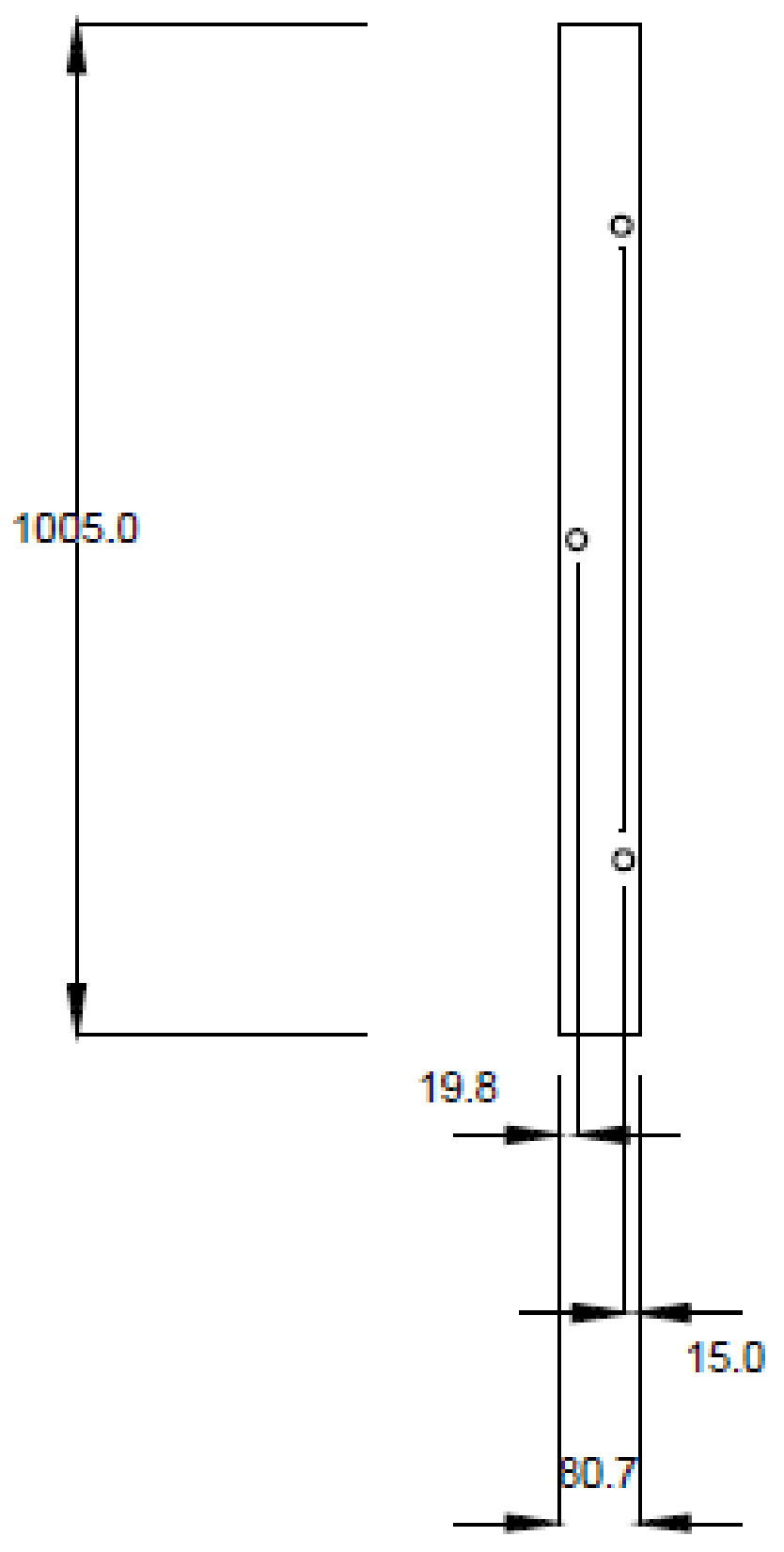
Figure 3.
(a) The left solar mount from the top view and (b) side view. All measurements in mm.

Figure 4.
The bottom solar mount (a) showing top view of hole positions and (b) the side view of the z-step. All measurements in mm.
Figure 4.
The bottom solar mount (a) showing top view of hole positions and (b) the side view of the z-step. All measurements in mm.
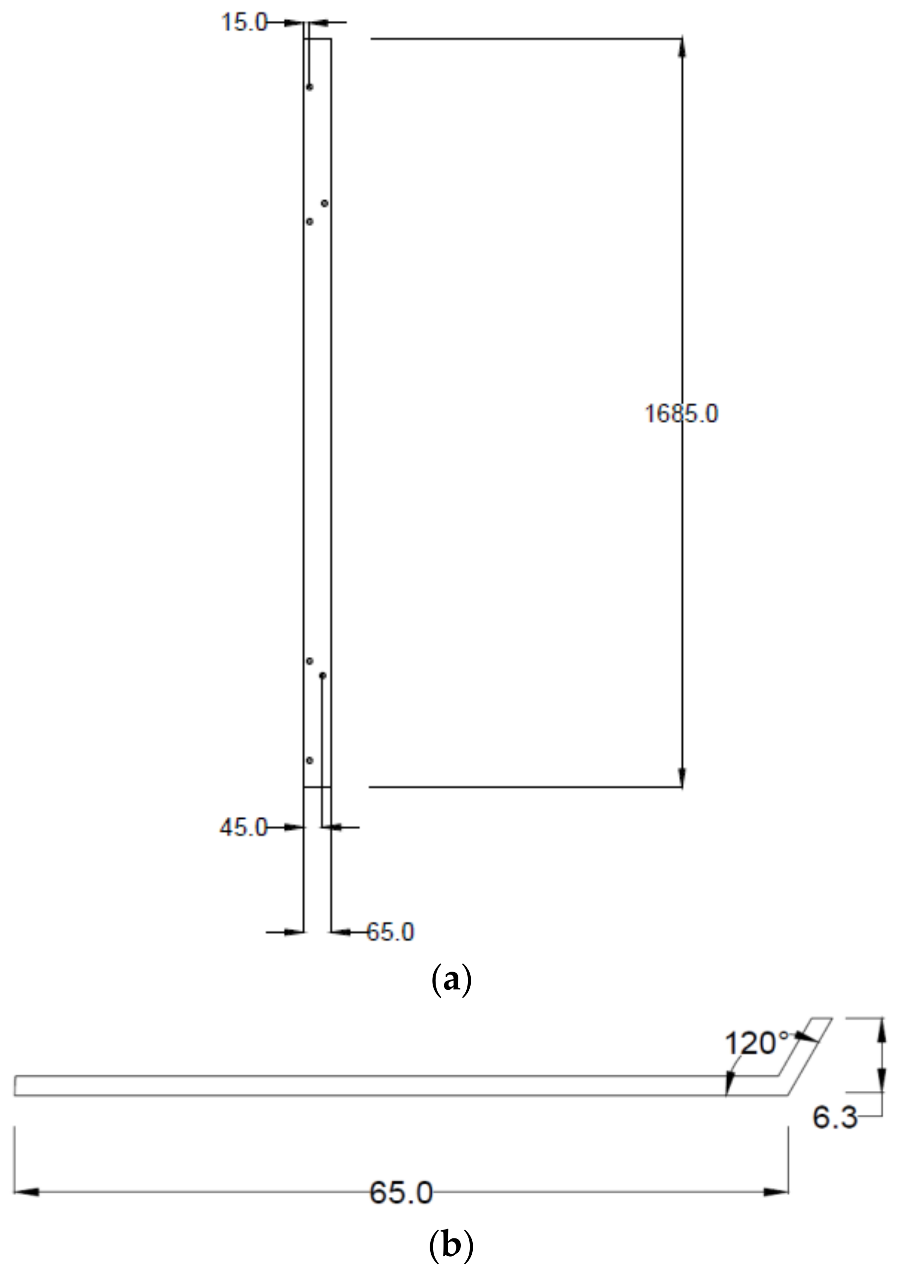
Figure 5.
(a) Physical dimensions of the PV modules used in mm; (b) the same module shown in 3 × 2 array 3-D with all four of the novel modifications added to it for perspective. Please note the lip of the module frame is exaggerated for clarity and is not to scale.
Figure 5.
(a) Physical dimensions of the PV modules used in mm; (b) the same module shown in 3 × 2 array 3-D with all four of the novel modifications added to it for perspective. Please note the lip of the module frame is exaggerated for clarity and is not to scale.

Figure 6.
Assembly of the left side aluminum component on the underside of the PV module (top of image shiny silver). All four aluminum components are mounted to the module similarly.
Figure 6.
Assembly of the left side aluminum component on the underside of the PV module (top of image shiny silver). All four aluminum components are mounted to the module similarly.

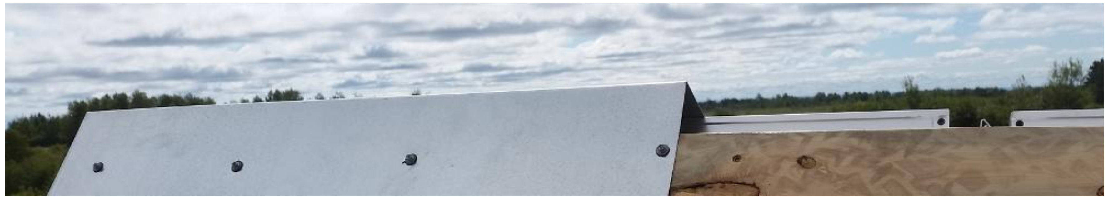
Figure 7.
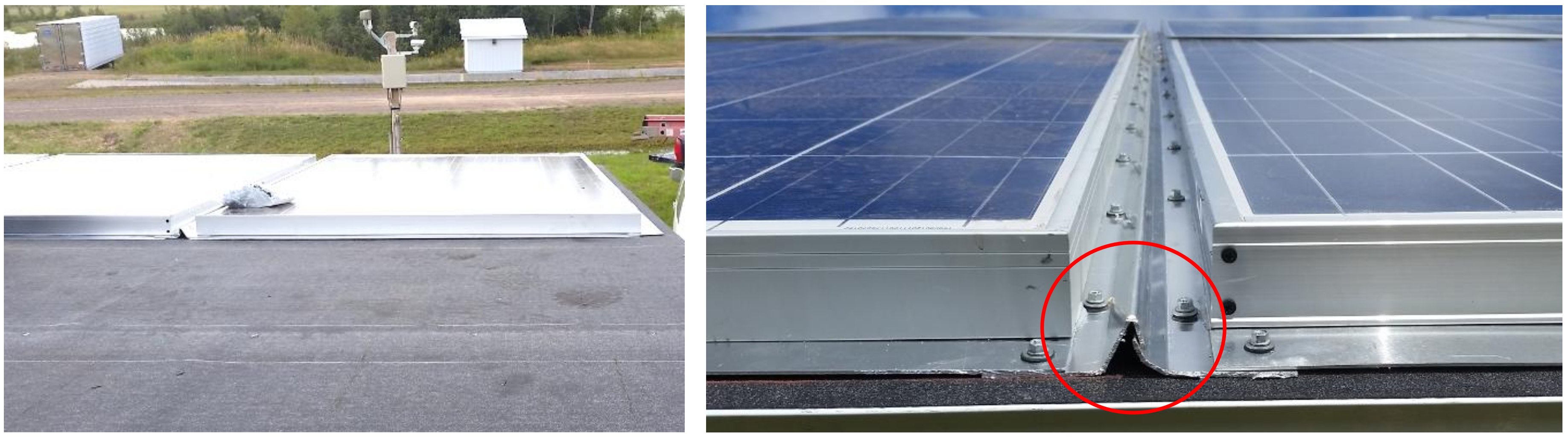
Installation of the first row of adapted PV modules on the bottom of the experimental roof (left) viewing from the peak of the roof. The roof felt roof deck protection is shown in the foreground. A bag of screws is shown on the first module for scale. In the background is one of the meteorological stations for the Keweenaw Research Center (KRC) PV systems testing field [35,36,37]. On the (right) is a detail of the overlap between the left and right aluminum components forming a vertical channel. In the red circle the overlap between the two sides is shown. The lip from Figure 3 is shown on the left which covers up the bend from Figure 4 (shown on the right). This creates a waterproof channel connecting the modules in the horizontal plane.
Figure 7.
Installation of the first row of adapted PV modules on the bottom of the experimental roof (left) viewing from the peak of the roof. The roof felt roof deck protection is shown in the foreground. A bag of screws is shown on the first module for scale. In the background is one of the meteorological stations for the Keweenaw Research Center (KRC) PV systems testing field [35,36,37]. On the (right) is a detail of the overlap between the left and right aluminum components forming a vertical channel. In the red circle the overlap between the two sides is shown. The lip from Figure 3 is shown on the left which covers up the bend from Figure 4 (shown on the right). This creates a waterproof channel connecting the modules in the horizontal plane.

Figure 8.
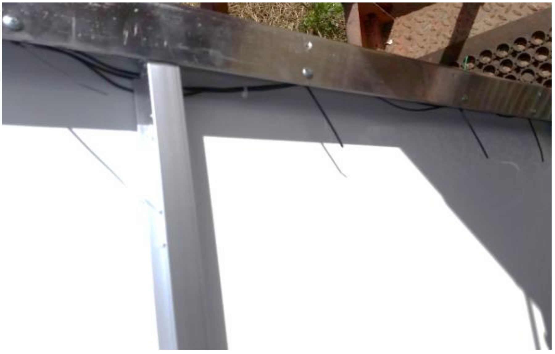
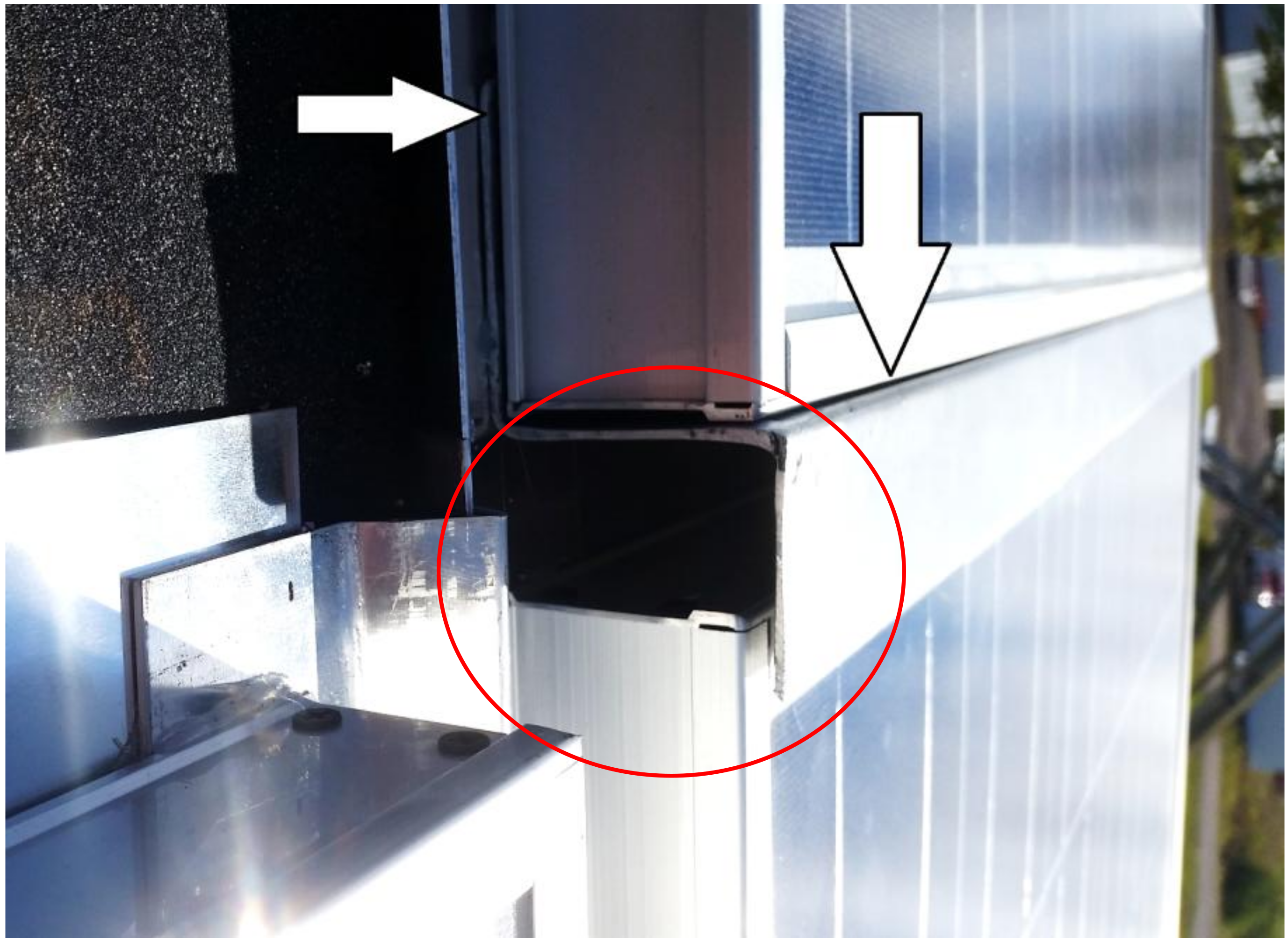
Detail of the installation of the second row of PV modules with the Z-overhang component from Figure 1 over the top of the modules in row 1. Note how the aluminum straight edge (from Figure 2) from the top of the first row of modules goes underneath the Z-overhang on the bottom of the upper row of modules (details with arrows). Wires can be run through these channels highlighted with a red oval and the module wires are sent through holes at the bottom of the module to prevent rain egress.
Figure 8.
Detail of the installation of the second row of PV modules with the Z-overhang component from Figure 1 over the top of the modules in row 1. Note how the aluminum straight edge (from Figure 2) from the top of the first row of modules goes underneath the Z-overhang on the bottom of the upper row of modules (details with arrows). Wires can be run through these channels highlighted with a red oval and the module wires are sent through holes at the bottom of the module to prevent rain egress.

Figure 9.
Detail of the final (upper) row of PV modules being covered by an aluminum channel to prevent water intrusion from the top of the BIPV roofing system.
Figure 9.
Detail of the final (upper) row of PV modules being covered by an aluminum channel to prevent water intrusion from the top of the BIPV roofing system.

Figure 10.
Six module building-integrated photovoltaic (BIPV) roof-mounted test array.
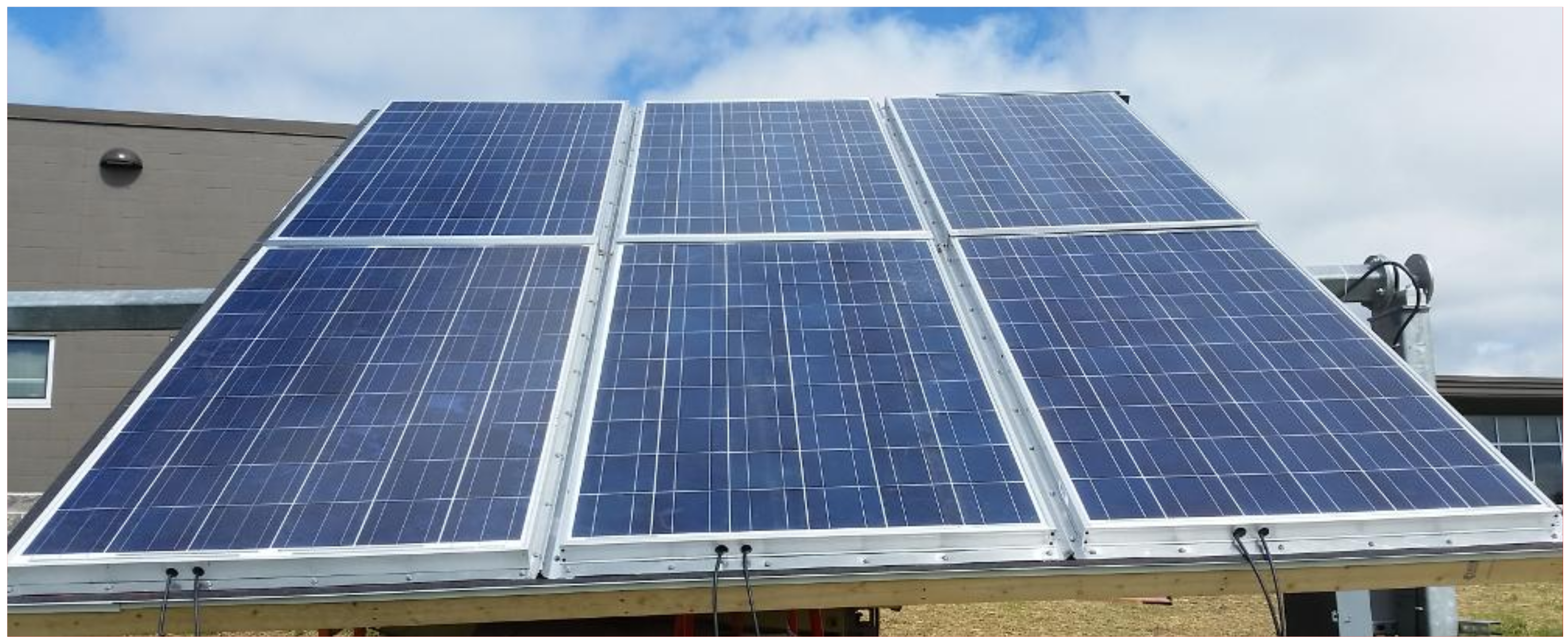
Figure 11.
Electronic schematic of the open-source monitoring and data logging system.
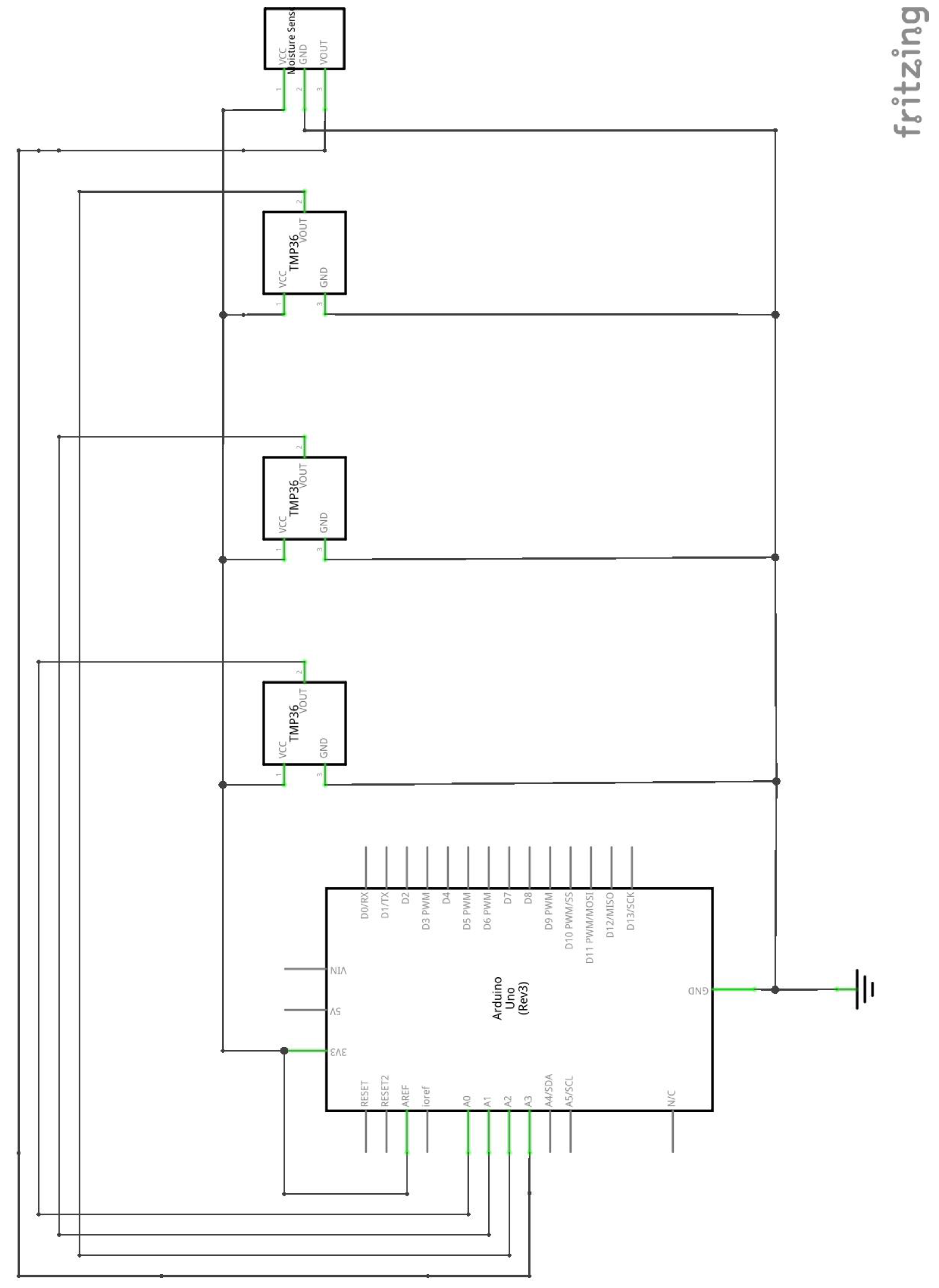
Figure 12.
Total daily liquid precipitation per day at test site in inches for one year.

Figure 13.
Daily absolute maximum of ambient air temperature at test site in degrees Celsius through 2016. Shaded region is a guide for the eye indicating freezing temperatures.
Figure 13.
Daily absolute maximum of ambient air temperature at test site in degrees Celsius through 2016. Shaded region is a guide for the eye indicating freezing temperatures.

Figure 14.
Hourly peak wind speed at 2 m in miles per hour (MPH) through 2016.

Figure 15.
Temperature as a function of time in the monitored BIPV system for an example day in November.
Figure 15.
Temperature as a function of time in the monitored BIPV system for an example day in November.

Table 1.
Bill of materials (BOM) of conventional photovoltaic (PV) module conversion to PV slate per module. All prices in U.S. dollars (USD).
Table 1.
Bill of materials (BOM) of conventional photovoltaic (PV) module conversion to PV slate per module. All prices in U.S. dollars (USD).
| Item | Quantity | Cost | Price Per Module (USD) | Source |
|---|---|---|---|---|
| 1/16′′ Sheet Aluminum | 0.448 m2 | $143.60/40 ft2 (3.72 m2) | 17.29 | [29] |
| Felt Roof Deck Protection | 1.56 m2 | $17.50/216 ft2 (20 m2) | 1.37 | [30] |
| Neoprene washer and self-tapping fastener | 30 | $16.58/250 | 1.99 | [31] |
| Polyurethane Roof and Flashing Sealant | 1/6 container | $5.85/container | 0.98 | [32] |
| Fasteners (nuts/bolts) | As needed | >$0.10 | 1.00 | |
| Total | --- | -- | 22.63 |
© 2017 by the authors. Licensee MDPI, Basel, Switzerland. This article is an open access article distributed under the terms and conditions of the Creative Commons Attribution (CC BY) license (http://creativecommons.org/licenses/by/4.0/).
Share and Cite
MDPI and ACS Style
Pearce, J.M.; Meldrum, J.; Osborne, N. Design of Post-Consumer Modification of Standard Solar Modules to Form Large-Area Building-Integrated Photovoltaic Roof Slates. Designs 2017, 1, 9. https://doi.org/10.3390/designs1020009
AMA Style
Pearce JM, Meldrum J, Osborne N. Design of Post-Consumer Modification of Standard Solar Modules to Form Large-Area Building-Integrated Photovoltaic Roof Slates. Designs. 2017; 1(2):9. https://doi.org/10.3390/designs1020009
Chicago/Turabian StylePearce, Joshua M., Jay Meldrum, and Nolan Osborne. 2017. "Design of Post-Consumer Modification of Standard Solar Modules to Form Large-Area Building-Integrated Photovoltaic Roof Slates" Designs 1, no. 2: 9. https://doi.org/10.3390/designs1020009