
Performance Explorations of a PMS Motor Drive Using an ANN-Based MPPT Controller for Solar-Battery Powered Electric Vehicles

1
School of Electrical Engineering, VIT University, Vellore 632014, Tamil Nadu, India
2
Department of Railroad and Electrical Engineering, Woosong University, Jayang Dong, Dong-Gu, Daejeon 34606, Republic of Korea
*
Author to whom correspondence should be addressed.
Designs 2023, 7(3), 79; https://doi.org/10.3390/designs7030079
Submission received: 20 April 2023
/
Revised: 13 June 2023
/
Accepted: 14 June 2023
/
Published: 16 June 2023
(This article belongs to the Collection Editorial Board Members’ Collection Series: Smart Energy Systems Design)
Abstract
:Solar energy can function as a supplementary power supply for other renewable energy sources. On average, Vellore region experiences approximately six hours of daily sunshine throughout the year. Solar photovoltaic (PV) modules are necessary to monitor and fulfill the energy requirements of a given day. An artificial neural network (ANN) based maximum power point tracking (MPPT) controller is utilised to regulate the solar photovoltaic (PV) array and enhance its output. The utilisation of this controller can enhance the efficiency of the module even in severe circumstances, where reduced current and torque ripples will be observed on the opposite end. The motorised vehicle has the capability to function at its highest torque level in different load scenarios as a result. The proposed method is expected to provide advantages in various electric vehicle (EV) applications that require consistent velocity and optimal torque to satisfy the load conditions. The study employs a solar battery that is linked to an SVPWM inverter and subsequently a DC-DC boost converter to supply power to the load. An Artificial Neural Network (ANN) based Maximum Power Point Tracking (MPPT) control system is proposed for a solar battery powered Electric Vehicle (EV) and the system’s performance is evaluated by collecting and analysing data under adjustable load conditions to obtain constant parameters such as speed and torque. The MATLAB® Simulink® model was utilised for this purpose.
1. Introduction
The power industry is exploring new forms of renewable energy to help meet rising electricity demands as natural ecological resources become exhausted. Using sources of renewable electricity is one way to reduce the amount of carbon dioxide in the atmosphere and combat global warming. Modern renewable energy sources are dominated by solar photovoltaic systems because of their simple construction. It has been discussed how solar panel systems may be positioned differently and function in a variety of designs [1]. It is possible to increase the effectiveness of solar systems using maximum power point (MPP) controllers and power electronics [2]. The most effective way to determine the maximum power output is to use of one of the many techniques that have been devised. Under rapidly changing climatic circumstances, the majority of MPP algorithms in use today are ineffective due to sluggish and imprecise tracking and oscillation. Their usage efficiency suffers as a result. To solve this problem, an ANN-based control mechanism is proposed. To lessen unequal irradiance on this PV module, two distinct MPPTs are utilized in this instance. A bypass diode is employed to boost energy harvesting and to remove hotspots, while the PV string is simply linked in series to the block diode to stop the reverse current from existing load [3]. The MPP’s two-stage technique is used by the ANN-based MPPT to demonstrate its independence over time-dependent and transactional characteristics, since the MPP being monitored by PV led to circumstances without the need for time increments [4]. Differential evolution (DE), artificial neural networks (ANN), and conventional MPPTs can be used to address rapid changes in radiation and temperature, as well as the nonlinear properties of arrays [5]. When compared to the conventional incremental conductance method, our proposed MPPT approach significantly improves performance. This maximum power point tracking technique is based on ANN technology. When compared to Perturb and Obsevartion (P&O) controllers and incremental conductance, the abrupt shift in patterns occurs faster. A neural network can quickly improve efficiency, manage uncertainties, and solve issues without previous information. The learning algorithm changes layer weights in the artificial neural network to track MPPs more quickly [6]. NN controllers are efficient and responsive under both rapidly changing irradiance and partial shade.
Intelligent approaches outperform traditional ones, and artificial intelligence solves the disadvantages of Particle swarm Optimisation (PSO), Grey Wolf Optimisation (GWO), Genetic Algorithms (GA), Fuzzy Logic (FL), and others. Design and implementation complexity matter. In contrast to P and O’s inability to match pace with the MPPs when solar irradiation is fluctuating rapidly, the ANN approach can swiftly do so. Furthermore, ANN has low-frequency oscillation near the MPP, while the P and O method exhibits strong oscillation. The introduction of a mean square error (MSE) increases the network’s accuracy and increases the training network’s efficacy [7]. The utilisation of the two-level genetic algorithm technique has been documented in the literature [8] for the purpose of assessing parameters that affect battery power, such as temperature, light intensity, and junction temperature. For the purpose of tracking and managing solar heat from such a hybrid system, Particle Swarm Optimization (PSO) is utilized [9]. For boost converters for isolated solar systems, a back- propagation-focused multilayer deep neural network with a 10° temperature change MPPT is employed to reduce long-term system losses and boost conversion efficiency [10]. Energy conversion efficiency ranges from 12 to 20 percent for photovoltaic modules. The associated load and the PV system both have an impact on energy conversion loss. An MPPT and DC-DC converter, which can only reach the load voltage at maximum power point levels, avoids this [11]. Our tropical country of India has not researched solar energy.
Utilising solar battery power technology [12], a Permanent Magnet Synchronous(PMS) motor drive is linked to an MPPT controller with an inverter to improve its electric driving system performance. A solar array’s three-phase inverter compensates for output voltage and current distortion to increase electricity quality even in abnormal conditions [13]. When managing the PMS motor’s torque to ensure optimal torque control, a genetic algorithm is used to generate better torque ripple performance [14]. The use of neural vectors for spatial vector modulation and a comparison of neural networks with traditional systems have both been presented [15]. The advantage of our ANN-created MPPT algorithm over other traditional algorithms is that it can control MPPs.
This study designs a MATLAB® Simulink® mathematical model of the proposed system. The mathematical model incorporates a permanent magnet synchronous motor, PV cell, battery, and parallel control method. This paper’s main contributions:
- The study focuses on the topology of the proposed system, not its actual feasibility.
- The design attempts to accommodate realistic auxiliary losses to the extent that mathematical modelling permits. This is to guarantee a step toward resemblance and proximity to real-world outcomes to attempt to showcase the potential of the proposed system.
- The study contributes to proving the functioning of the suggested system in a test condition with diverse scenarios to display its robust architecture.
Previous methods for MPPT include P&O, Incremental Conductance (INC), CV, and CI (constant voltage, constant current). There are several issues with each of these methods, and they cannot function in partial shaded condition (PSC) environments. Observing the global MPP under PSCs is difficult for traditional algorithms; even if they do manage to achieve global maximum power point tracking (GMMPT), doing so takes an extensive amount of time and results in poor tracking accuracy and significant oscillation. This means that effective algorithms are crucial for GMPP extraction.
- ➢
- Solar panels with MPPT have been utilised for commercial and residential purposes, but electric battery vehicles are the first mobile usage.
- ➢
- The data that we used to train the ANN is from NASA’s prediction of worldwide energy resources. https://power.larc.nasa.gov/data-access-viewer (accessed on 18 April 2023).
- ➢
- Most literature utilises irradiance and panel temperature sensors which are costlier and may raise overall system costs. Such sensors are also inaccurate and fragile. The suggested ANNMPPT tracks maximum power points effectively and efficiently.
The MPPT technique’s primary innovations:
- ANN-based MPPT algorithms do not require expensive irradiance and temperature sensors.
- The suggested technique increases tracking performance by readily integrating into the existing MPPT method.
This article combines optimisation with artificial intelligence to improve photovoltaic (PV) array tracking and power harvesting. Due to their exploration and optimisation skills, algorithms can be employed in artificial neural network training to find the most effective weights to minimise error.
Section 2 covers solar array mathematics. Section 3 presents the MPPT algorithm. Section 4 covers PMS motor drive mathematical modelling. Section 5 uses MPPTs and DC-DC converters to boost PV output and motor drive battery supply. Section 6 shows PMS-driven electric car ANN MPPT MATLAB Simulation results. Section 7 summarises the study as a whole.
2. Solar Array Mathematical Formulation
The photovoltaic cells are used in solar photovoltaic systems. Panels are formed by grouping cells, while arrays are created by grouping panels. Equations (1) and (2) specifically reference the ideal photovoltaic cells, which have been described by the fundamental mathematical Equation (2).
where Imc is the module current, Iil is the insolation light current, q is e-, k is Boltzmann’s constant, N is the diode identity, and Vmv is photovoltaic cell voltage [16].
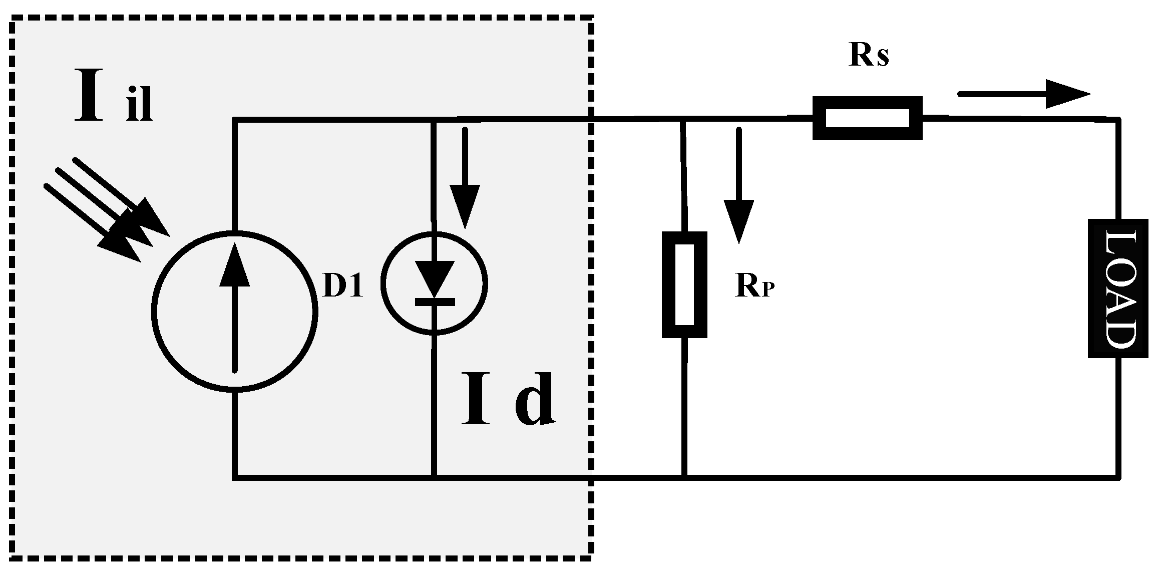
Since an actual PV module is made up of several PV cells, the fundamental equation for a PV system does not capture I-V characteristics [17]. Instead, extra parametric variables such as parallel and series resistances (Rp and Rs), which are shown in Figure 1, are needed. The solar cell’s mathematical equation, given in Equation (2), provides the foundation for modeling PV modules. Figure 1 shows the equivalent circuit of PV module.
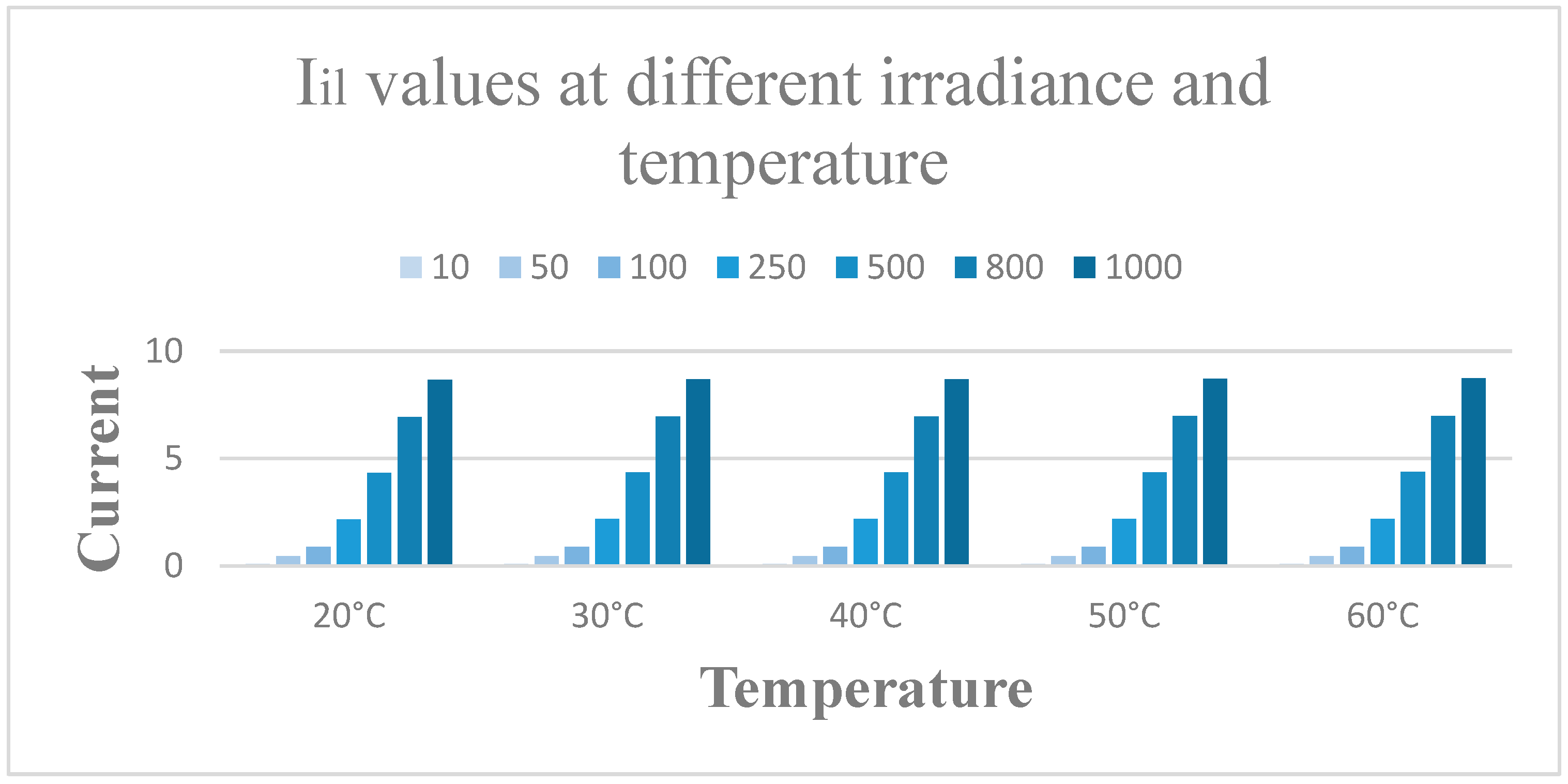
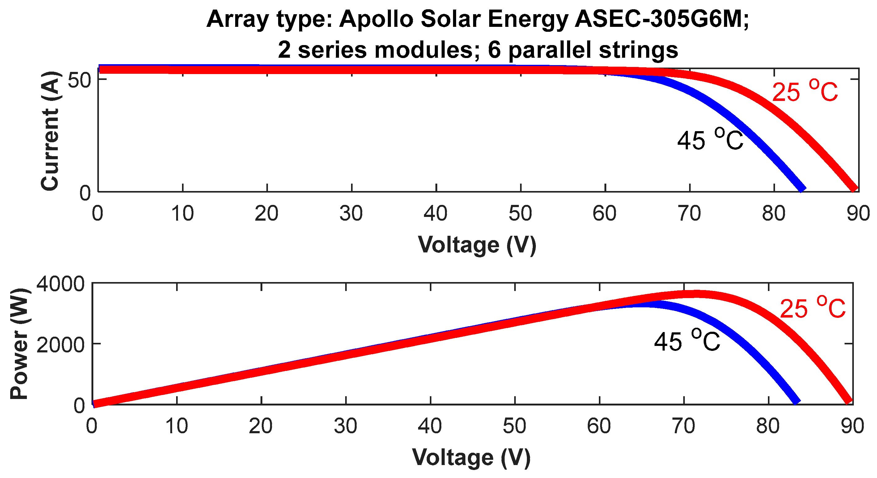
where Imc is the module current in Amperes, Rs is series resistance in Ω, Rp is the shunt resistance in Ω, and Vmv is the module voltage. Current values at different irradiance and temperature is shown in Figure 2.
where Pirr is the applied irradiance in W/m2, Pr is the reference irradiance, Is is the short circuit current of the module, Ts is the temperature coefficient of Is in A/°K, and Tjt and Tr are the applied and reference temperatures in kelvin.
Equation (4) gives the reverse saturation current of the module under nominal conditions as well as a reference temperature [18].
where Is is the saturation current and N is the total number of cells in a module. Even as the applied temperature rises, the voltage of the module drops, as shown by Equation (5).
Whereas the saturation current is as follows:
Egois the energy in the band gap in J/C and Rs is the shunt resistance, where small variations in the series resistance will have an impact on the output power of the PV, as the shunt resistance (Rs) is inversely related to the leakage current. Photovoltaic cells only generate about two watts when the circuit is open at between 0.5 and 0.7 volts [19]. To provide the necessary power, the cells must be linked in series. This single diode module array’s basic current is determined by Equation (7).
Nse and Npr refer to the number of series and parallel connected modules per string (two for series, six for parallel). Based on the 1soltech1STH-250 W polycrystalline solar module’s data sheet specifications, at a maximum power of 305 W with 72 cells per module, having an open circuit voltage of 44.88 V with a short circuit current of 8.95 A and a voltage at a maximum point of 35.59 V with a current at a maximum power point of 8.57 A. The PV array was modeled for 1000 W/m2 at 25 °C. The solar panel model in the simulation was constructed under typical test settings based on the aforementioned characteristics [20].
3. Stated MPPT Algorithm
The MPPT control technique optimises PV module performance under various environmental parameters like solar irradiance and temperature [21]. As is widely known, solar irradiation and temperature significantly affect the PV system’s nonlinear output power characteristics as functions of irradiance and temperature curves. Daily sun irradiation fluctuates sharply. To maximise energy generation, the PV system’s operating point must fluctuate when the PV array’s MPP varies. Thus, MPPT maintains the PV array’s MPP. MPPT automatically determines the current at maximum power point (IMPP) or voltage at maximum power point (VMPP) that a PV array should operate at to provide the maximum output power at maximum power point (PMPP) at a certain temperature and irradiance level. Most MPPT methods respond to irradiance and temperature variations, while others operate more effectively in stable temperatures. Some MPPT methods are open-loop and need periodic fine-tuning, but most automatically adjust to array ageing. In our case, the module will be connected to a power converter that regulates the PV array-to-load current.
MPPT methods can precisely monitor the maximum power point (MPP); many techniques have been devised. The majority of MPPT algorithms currently in use suffer from the drawbacks of sluggish and incorrect tracking, as well as oscillation under quickly changing meteorological circumstances [22]. As a result, usage efficiency is decreased. This study offers an MPPT control technique based on an artificial neural network to address these drawbacks [23]. This technique surpasses all other conventional techniques in terms of system performance and effectiveness. A multilayer feedforward network is employed in this method [24]. To calculate the irradiance and temperature levels from the photovoltaic array current and voltage data, this study uses a deep neural network centered on MPPT incorporated with polyphase offline training. The ANN uses supervised learning to eliminate mistakes by calculating the necessary multiplication factor [25]. The methods described can deliver superior performance with fewer training sets under steady and transient conditions, even under rapidly varying environmental circumstances, since a power amplifier delivers the load with the highest possible output voltage [26]. In the simulation, a training network with a supervised learning feedforward algorithm is used to compensate for the solar array’s nonlinearity. Figure 3 depicts the flow diagram for the proposed ANN-MPPT algorithm. According to photovoltaic cells’ output characteristics, they have an ideal operating point at a specific cell temperature and level of illumination that is known as the most powerful point. Solar cells have variable maximum power points under various temperatures and light circumstances; even under identical conditions, the output power will fluctuate depending on the operating voltage used by the PV cell. It is therefore necessary to monitor the maximum power point of solar cells so that they can continuously operate at their maximum efficiency.
Currently, the perturbation and observation technique (P and O) and incremental conductivity approach (INC) are the most popular MPPT algorithms. P and O has a straightforward structure, fewer measurable parameters, and is simple to execute. However, selecting a step disruption that would satisfy the demands of tracking precision and speed is challenging. Furthermore, it frequently results in false positives. However, we have identified two circumstances in which the present change is minimal.
One instance is when a PV cell operates in the range of a continuous current source. The major control step can now be chosen using the aforementioned procedure. The second instance is that the MPP of the PV cell is circumvented. The control step currently needs to be brief, which contradicts the first instance. Consequently, this improved control algorithm is unable to produce more effective control results.
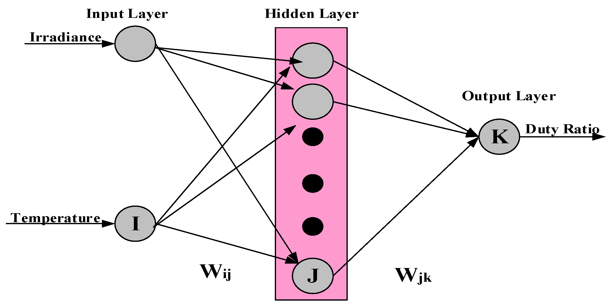
ANNs are AI technology, and AI outperforms conventional methods. Traditional approaches fail to monitor maximum power points and respond slowly to fast temperature and irradiance changes. Figure 3 shows an overview of MPPT ANN, Including solar temperature and irradiance inputs. The neural network targets the DC-DC converter duty ratio and will offer a duty ratio for each solar temperature and irradiance fluctuation to maximise each power point. Levenberg- Marquardt training algorithms create the network when the duty ratio and ANN are trained for different sun irradiation and temperature values. Adjusting layer weights during neural network training yields the desired results. Training weights are adjusted to follow objective values with minimal inaccuracy. ANN’s performance is measured using mean squared error (MSE).
Training using the Levenberg-Marquardt method yields the network. In order to train the ANN, we compute the duty ratio for each possible set of solar irradiance levels as well as temperature values. During training, the neural network’s weights in each layer are adjusted until the desired outputs are achieved.
Mean squared error (MSE) measures how well a regression line matches a set of data points. Its value matches the predicted squared error loss and risk function. Mean square error is calculated by averaging the squared errors from the data analysis in respect to a function. Throughout the training process, the weights are fine-tuned to obtain the most accurate tracking of the goal values as possible. Mean squared error is used as the ANN’s performance metric. The mean squared error is calculated as follows:
where ti is the target and ai is the present output.
Trial and error determine hidden layers. Output is boosted by the converter duty ratio. After training, any ANN algorithm can be applied. Learned incrementally, duty ratio data for the boost converter are recorded while changing irradiance and temperature inputs for the PV array to monitor solar panel power. To test the neural network, certain training points are kept.
3.1. Effectiveness of a Conventional MPPT Controller with Distinct Irradiance (G) & Persistent Temperature (T)
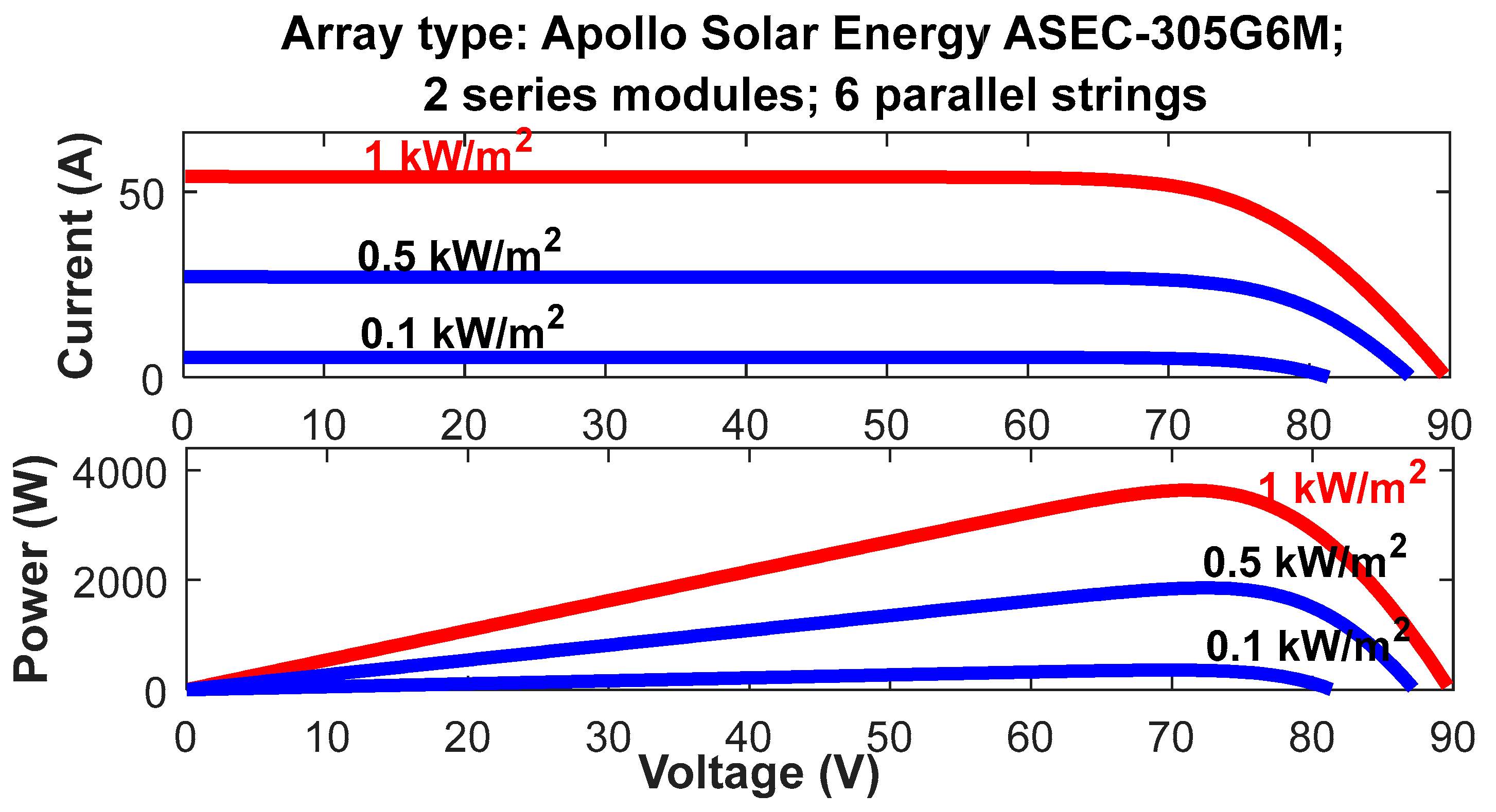
When the irradiance fluctuates between 100, 250, 500, 800, and 1000 W/m2, the current, voltage, and irradiation levels of the PV are seen to immediately increase [27]. As a result, the PV array’s overall net power increases. The conditions mentioned above are represented by the typical curves in Figure 4 below.
3.2. Results of Standard MPPT Controller Testing with Variable T, Constant G
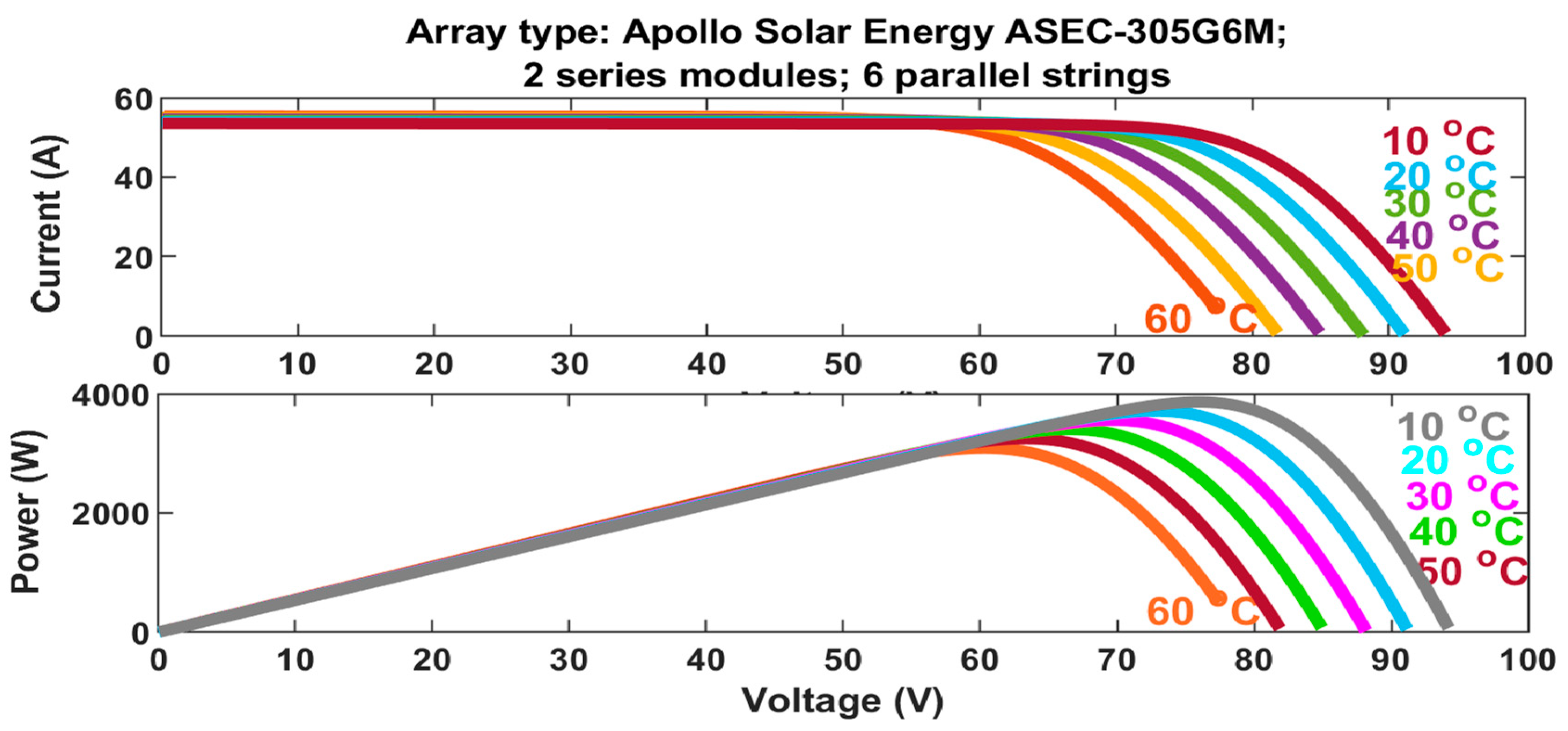
The PV current increases as the photovoltaic array voltage quickly increases from 20 °C to 50 °C and eventually to 60 °C. This reduces PV array output. The curves shown in Figure 5 indicate these characteristics.
3.3. Performance of MPPT Algorithm Controller under Temperature and Irradiance Change
When both temperature and irradiance levels are changing, the voltage decreases until the temperature rises, which causes the module current to increase. The opposite is also true. Additionally, there is not a significant increase in voltage until the irradiance increases, and vice versa.
4. Mathematical Modeling of PMSM
Permanent magnet synchronous motor (PMSM) drives are highly favoured by industry leaders in the automotive sector due to their potential for high power density, high speed, and excellent operating efficiency. PMSMs are categorised based on the location and style of the permanent magnets inside the rotors [28]. Three common types of PMSM are surface, embedded, and interior/buried. Both inset rotor and surface mounted PMSMs are referred to when the permanent magnets are exposed to an air gap. Due to the fact that the q-axis inductance may be substantially larger than the d-axis inductance [29], the magnets in the interior permanent magnet synchronous motor (IPMSM) are hidden within the rotor and have a greater capacity for flux-weakening. One of the major drawbacks of PMSM drives is their lack of excitation control. The internal Electro Magnetic Field (EMF) of a motor increases in tandem with its rotational velocity. As this style of operation often employs constant volts-per-hertz control, this type of behaviour is preferred in the so-called constant torque range. The related frequency converter’s voltage limit, however, is reached as the speed rises. This is referred to as the motor’s “flux-weakening operation,” and it follows its “neutral” state. As the speed of the converter increases, it becomes essential to increase the internal voltage to match the external voltage [30]. Since the inverter has to commutate a larger current at higher speeds, the power factor of the motor changes to leading.
In Cartesian coordinates, Equation (9) is used to represent the voltage expression for the PMSM, ignoring magnetization circuit saturation, eddy losses, and hysteresis losses [31].
The equation for the motor’s flux linkage is as follows:
The three windings’ flux linkage is represented by s. The motor’s voltages, resistances, and currents are represented by us, Rs, and is respectively [32]. The three-phase inductance is Ls, and the three-phase angle is [33]. is considered the motor flux linkage.
where Lm are mutual inductances, and Ll are inductance leakages. The motor’s torque can be computed as:
The motor’s pole pairs are denoted by Pn. The dynamic behaviour of the motor can be expressed by,
where J denotes the motor’s spinning inertia, B denotes its damping coefficient, and TL is its loading torque [34]. The motor’s angular speed is denoted by ωm. The motor’s primary specifications are presented in Table 1.
Phasor diagrams analyse surface and interior-mounted permanent magnet motors, whose control methods have advantages and disadvantages. The unity power factor control technique optimises system volt-ampere (VA), whereas the constant mutual air gap flux connection controls restrict air gap flux linkage. Constant torque angle control reduces the power factor but relates the electromagnetic torque to the stator current magnitude; energy-saving maximum efficiency controls decrease motor net loss.
4.1. Drive Topology
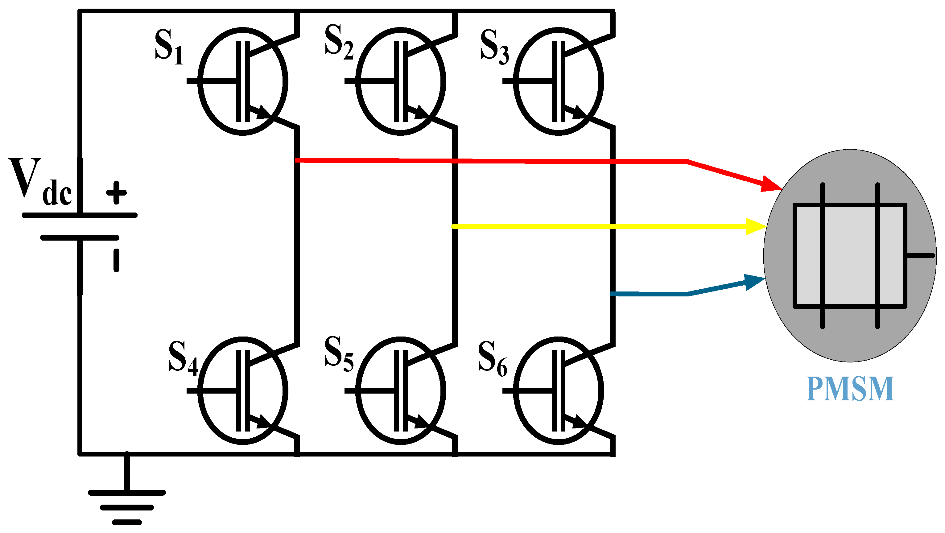
Three-phase Voltage Source Inverter (VSI)s handle moderate-to-high power. These topologies provide three-phase output voltage with customizable phase, amplitude, and frequency [35]. Three-phase dc/ac voltage source inverters enable changeable frequency and ac voltage magnitudes in motor drives, active filters, power systems, and uninterruptible power supplies [36]. Figure 6 displays a six-modulation-switched three-phase inverter, featuring diode-bridge rectifiers, Inductor-Capacitor (LC) or Capacitor(C) filters, and utility power supplies providing input, represented by dc [37].
Figure 6 depicts the PMSM’s three-phase inverter structure. S1–S6 represent the six Insulated Gate Bipolar Transistor (IGBT)s and their states [38]. S1 and S4 cannot switch on simultaneously for a single bridge in the case of a short circuit between Vdc and the ground. As a result, S4 switches off as soon as S1 does, and vice versa. As shown in Table 1, eight switching modes for three-phase alternative current motors are produced by six IGBTs. The eight vectors split the vector plane into six portions for the motor [39].
Two of the eight switching states represented in Table 2 result in output (ac) line voltages of zero. In this scenario, the higher or lower components are freely cycled by the ac line currents. The remaining states do not have zero ac line voltages. The inverter alternates between states to produce a certain voltage waveform. The subsequent ac line voltages are therefore made up of the discrete voltage values: V, 0, and V [40]. The modulating technique, which ensures the use of only the viable states, is used to select the states in order to produce the given waveform.
4.2. Three-Phase VSI Using Space Vector Pulse Width Modulation (SVPWM)
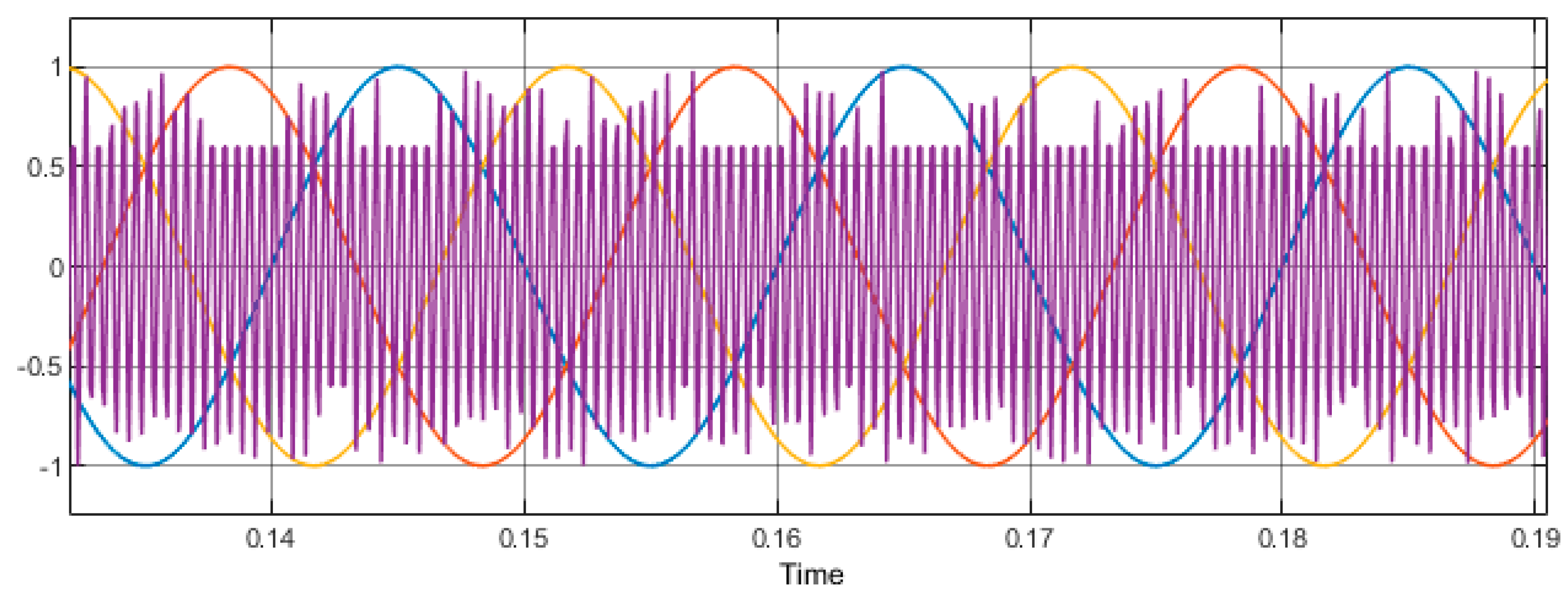
In three-phase inverters, space vector pulse width modulation (SVPWM) compares three sine waves phase-shifted by 120° to a very high-frequency carrier signal [41]. The signals are combined at a reference point where the comparator output is high when the sine wave, also known as the modulation signal, is greater than the saw tooth wave and low when the sine wave is smaller. Figure 7 shows this.
This section provides a sinusoidal pulse width modulation technique for a two-level converter that uses both solar panels and a battery pack as a Direct Current (DC) voltage source. To achieve a symmetric algorithm pulse with voltage balance, the fundamental concept and switching order of the SVPWM are provided. Through an ANN-based MPPT controller, this strategy is employed to regulate the inverter’s output voltage [40]. The DC voltage is changed into a 3-phase instantaneous voltage reference using this SVPWM method, as shown in Figure 7.
5. Proposed ANN MPPT Algorithm with PMSM as Load
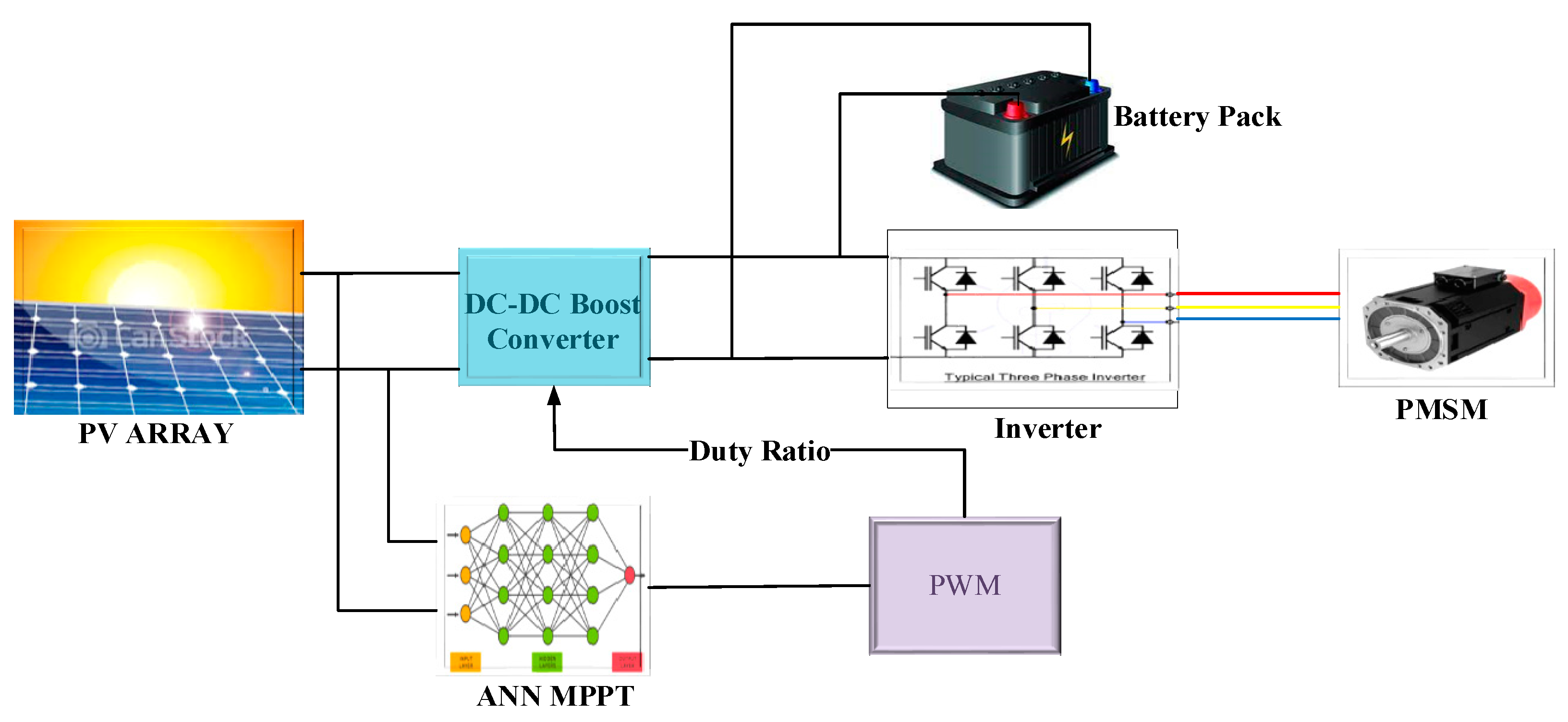
The next design depicts the intended architecture of the system through a DC converter. The solar array has six 250-watt photovoltaic modules that are coupled in series as well as in parallel to generate greater output voltage and current [41]. Under different circumstances, the suggested MPPT algorithm, which is based on an ANN, obtains the most power possible from the photovoltaic system.
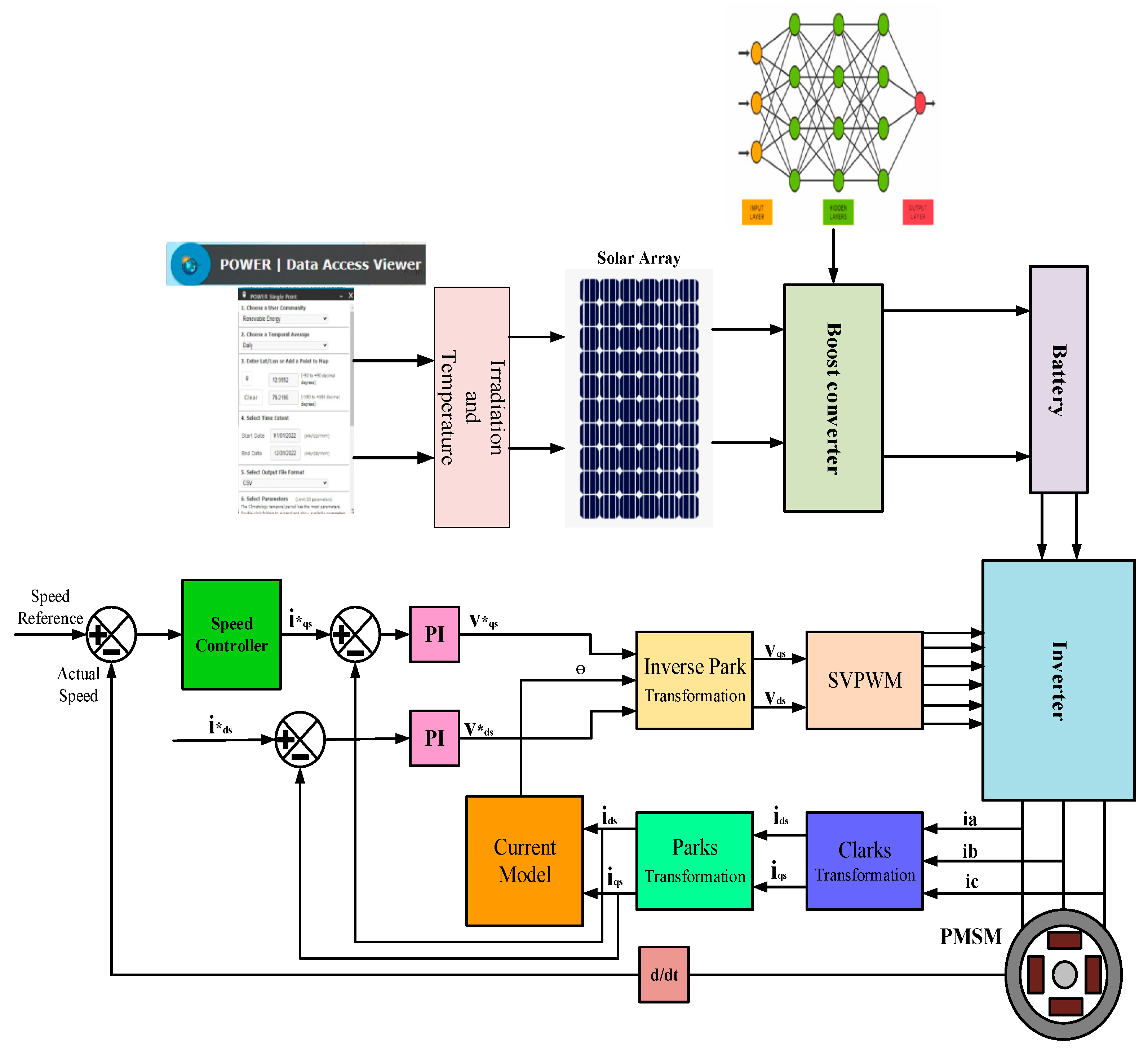
The power that reaches the solar array using the ANN MPPT algorithm is fed to the motor as well as a battery pack using a three-phase PWM-based voltage source inverter [42]. The energy stored in the battery is used when there is less power produced by the PV array due to dissimilar climatic conditions. As shown in Figure 8, a PMSM receives its three-phase power from VSI, and the drive axle of the vehicle is connected to the shaft of the motor along with the differential. The Matlab/Simulink model is shown in Figure 9.
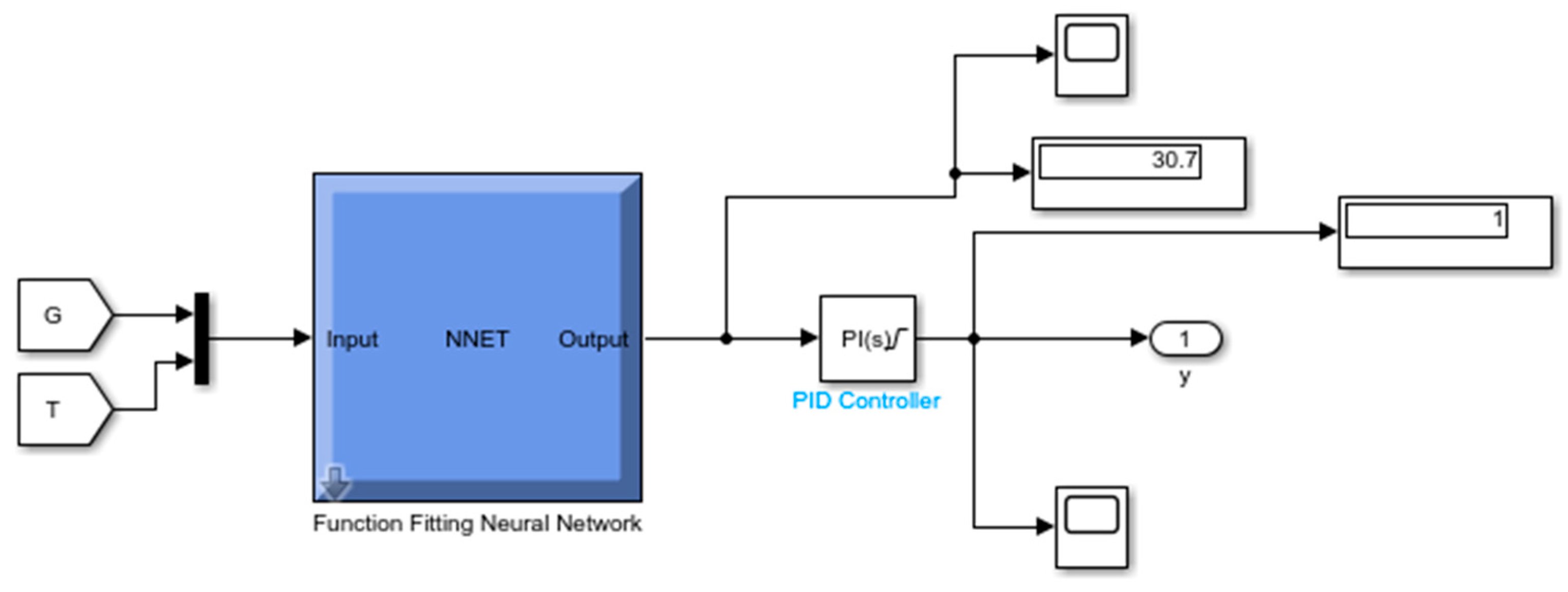
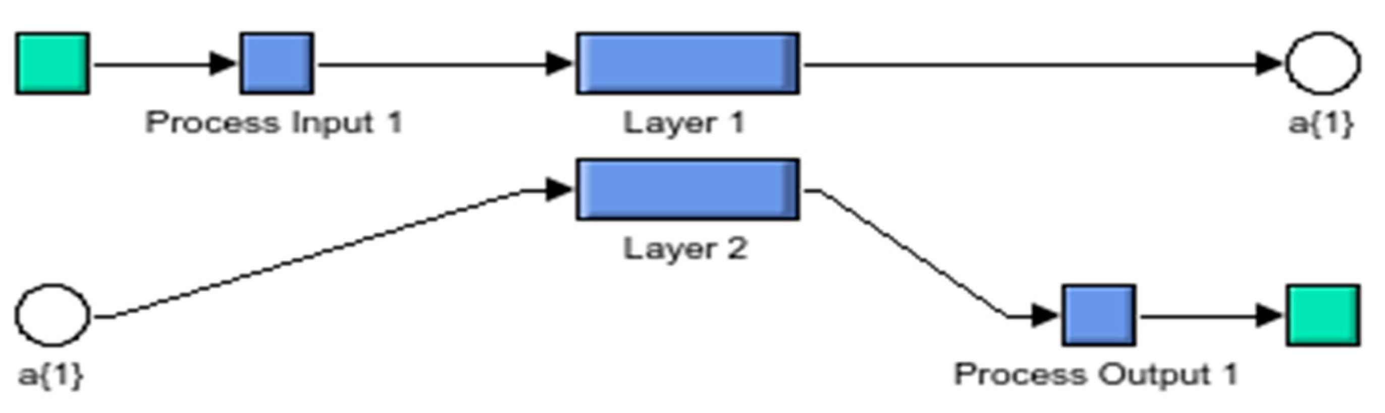
The final configuration of the proposed ANN MPPT is shown in Figure 10, which consists of its inputs and outputs. The inner layers of the proposed ANN are shown in Figure 11.
A MATLAB/Simulink model was developed for a proposed ANN MPPT-based solar-battery-powered electric vehicle driven by PMSM. Based on the irradiation (G)/temperature (T) the developed ANN MPPT extracts maximum power from the solar PV array, a DC-DC boost converter without a transformer boosts the power [42,43], which is further given as input to both batteries for storage and PMSM to drive the axle of the vehicle. The G and T values of an array are given as inputs to the neural network algorithm, and after several iterations, the output is given to DC Pulse Width Modulation (PWM) to generate gate pulses based on its duty cycle [44]. The DC link voltage is given to the battery pack at 80% State of Charge (SoC). A Space Vector Pulse Width Modulation (SVPWM) VSI gets its DC power from the battery and converts it into three-phase voltages given as input to the PMSM. The developed model gets maximum torque at different speeds using field-oriented control.
6. Results and Discussions
Simulink and MATLAB were used to create the suggested model. Solar irradiance (G) and temperature (T) are the module’s inputs. In standard test conditions (STC), a module with 72 cells produced 250 watts of power. Two modules form a solar PV array. The simulation found that the MPP can produce 3100 watts with an open circuit voltage (VOC) of 44.88 volts and a short circuit current of 8.95 amps. Figure 12 shows these results.
6.1. Results of a Simulation for an Asynchronous Motor Drive Using an Inverter
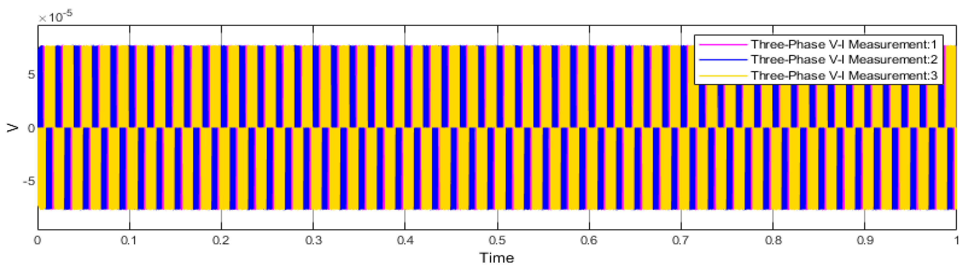
At 1400 rpm as a reference speed and 5 KHz as a switching frequency, the simulation goals were achieved. Here, a boost converter and an inverter are used by the motor driver to provide a 400 V supply. Figure 13 displays the inverter’s output voltage.
6.2. Asynchronous Motor Drive Simulation Results in the on Position
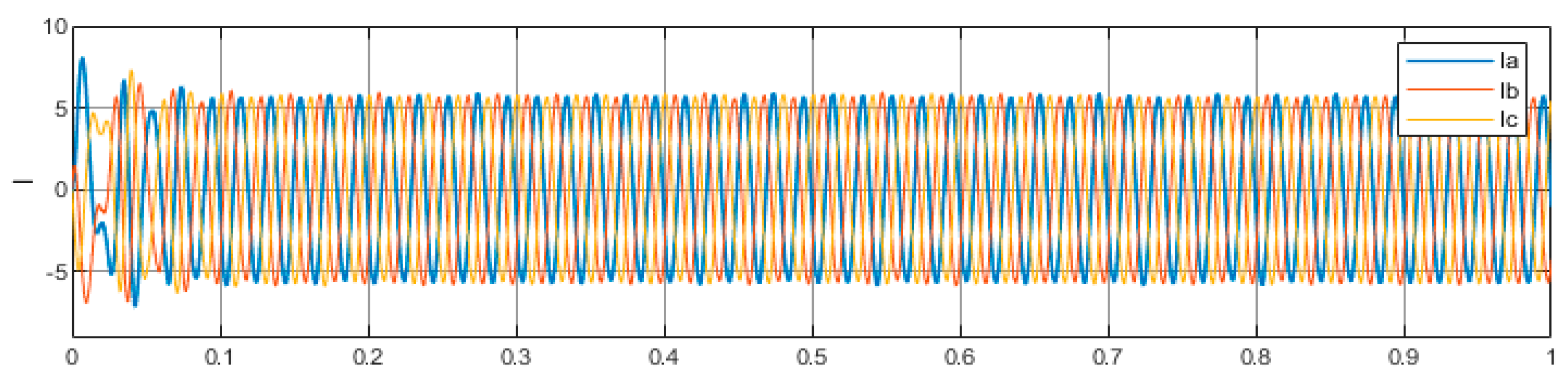
Starting ripple content and maximum torque currents are reduced to provide an early steady state for the PMS motor drive. The recommended MPPT produces 2.98 N-m, 7.596 A, and 1500 rpm of torque, a stator phase current, and speed. The torque’s ripple content was 0.31, a significant improvement over previous methods. Figure 14 shows this.
6.3. Results of PMS Motor Drive Simulation
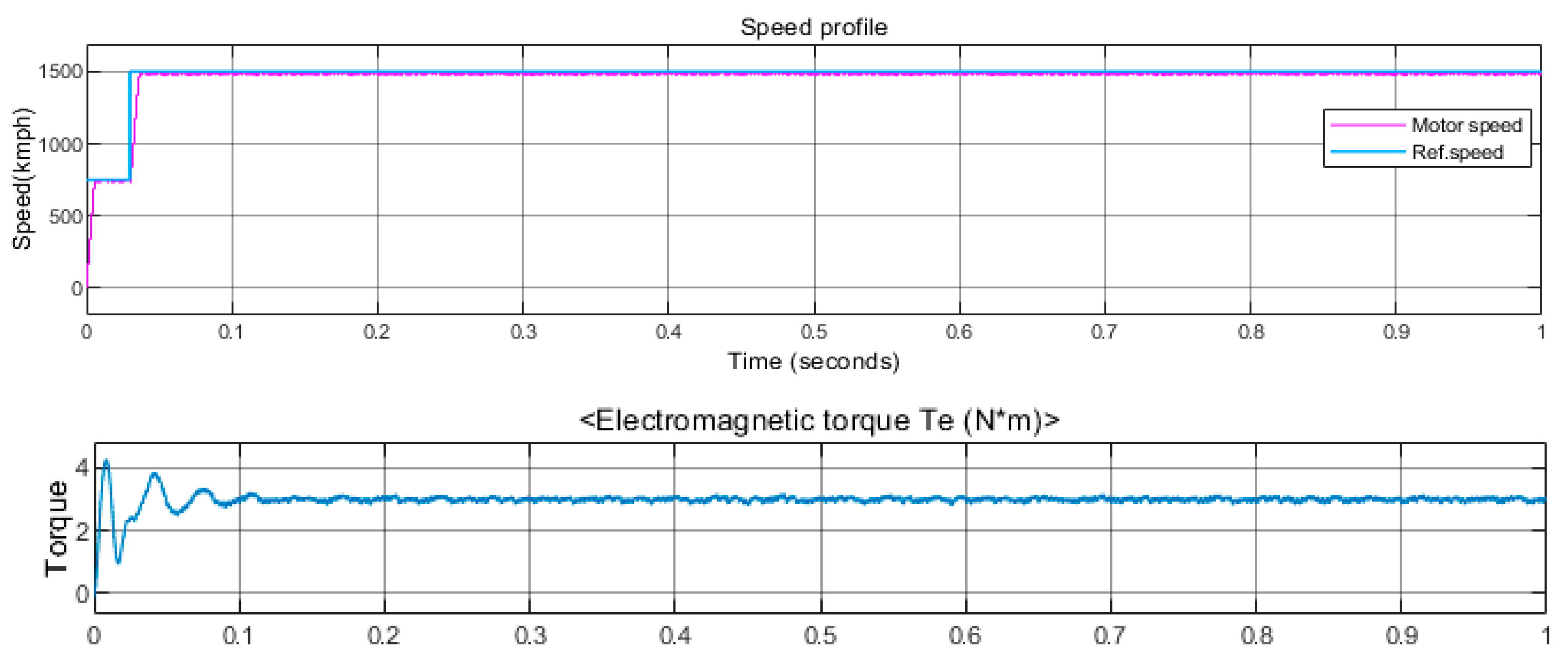
Figure 15 shows the steady-state responses of the stator phase currents, torque, and speed of the proposed MPPT. In this figure, the proposed MPPT controller results in a more optimal response from the torque and speed.
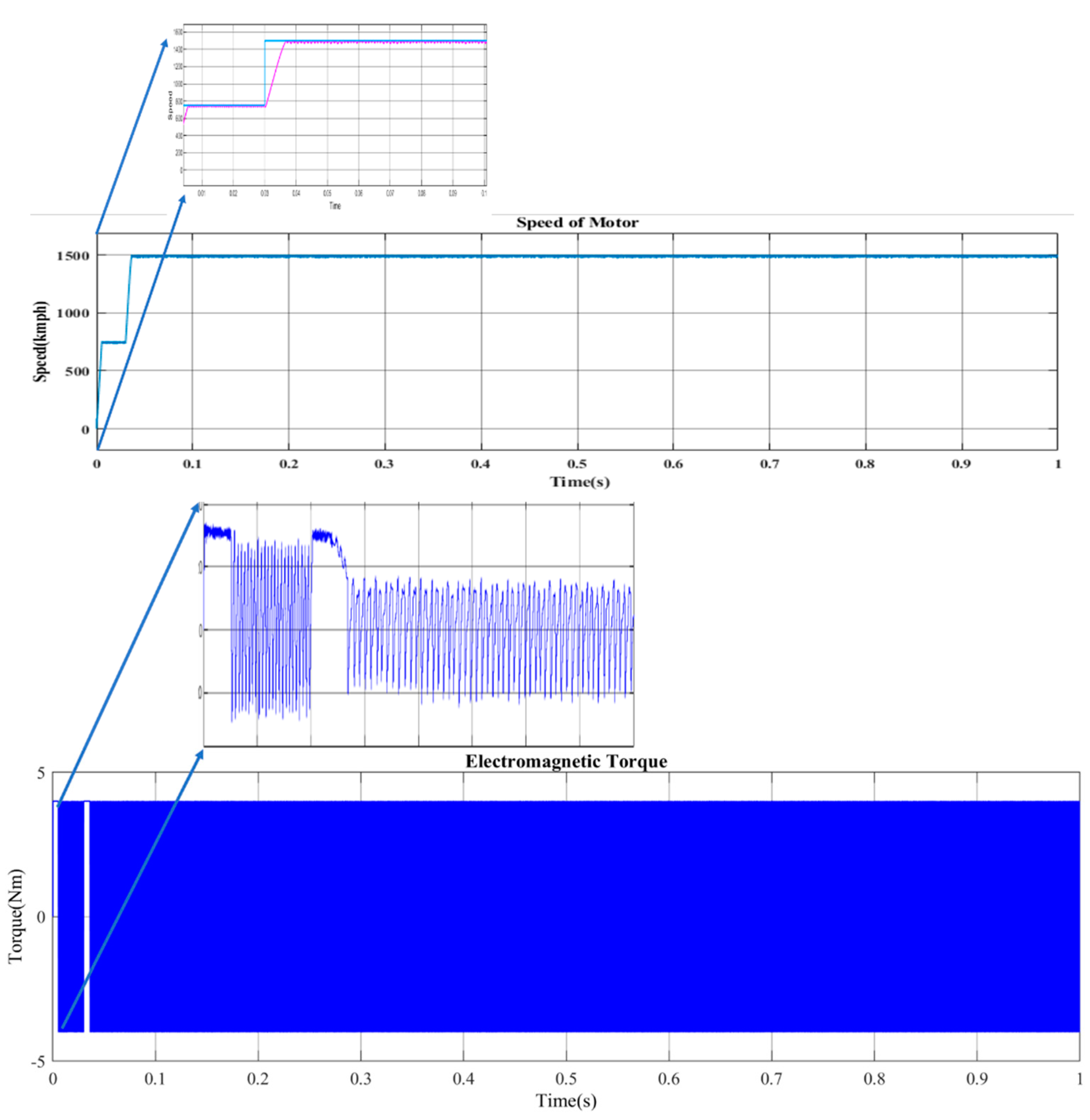
The ripple content of torque is reduced with the ANN block when compared to the torque without ANN; the comparison is shown in Figure 16.
6.4. Outcomes from the Results
- MPP is reached at minimum OCV (open circuit voltage) and Isc (short circuit current).
- While using the proposed MPPT, the rated torque and speed along with a stator phase current is achieved.
- The torque ripple content is reduced.
- Achieved sustainable improvement over other approaches currently in use.
- Attained better steady-state responses from torque and speed.
7. Conclusions
As the solution to energy demands and environmental problems, the usage of solar energy is indispensable. Using solar panels, the generation of power is encouraged by the MPPT algorithm. ANN-based MPPT controllers and PV array models were evaluated. The ANN-based MPPT controller reduced torque and stator phase current ripples. In this study, the proposed motor drive achieves both an early steady-state response and an improved speed response. As a consequence, the recommended MPPT with an ANN-based controller has considerably boosted the system’s power usage and efficiency. This is crucial for an electric vehicle. The developed model will be scalable for different electric vehicle applications as well. A PV system with a DC-DC boost converter and a space vector modulated inverter may further improve power quality and performance.
Author Contributions
Conceptualization, A.V.T.; methodology, W.R.S. and S.R.S.; validation, A.V.T., W.R.S. and S.R.S.; formal analysis, A.V.T., S.R.S. and W.R.S.; investigation, A.V.T.; resources, W.R.S. and S.R.S.; data curation, S.R.S.; writing—original draft preparation, S.R.S.; A.V.T.; writing—review and editing, A.V.T., W.R.S. and S.R.S.; visualization, A.V.T.; supervision, W.R.S. and S.R.S. All authors have read and agreed to the published version of the manuscript.
Funding
WOOSONG UNIVERSITY’s Academic Research Funding–2023.
Institutional Review Board Statement
Not applicable.
Informed Consent Statement
Not applicable.
Data Availability Statement
Not applicable.
Conflicts of Interest
The authors declare no conflict of interest.
Nomenclature
| ANN | Artificial neural network |
| MPPT | Maximum power point tracking |
| SVPWM | Space vector pulse width modulation |
| Imc | Module current |
| Iis | Insolation light current |
| q | Charge of electron |
| K | Boltzmann constant |
| N | Diode constant |
| Vmv | Voltage across PV cell |
| Rp | Parallel resistance |
| Rs | Series resistance |
| Pirr | Applied irradiance |
| Ts | Temperature coefficient |
| Tr | Reference Temperature |
| Ego | Energy in band gap |
| Nse | Series PV modules |
| Npr | Parallel PV modules |
| Impp | Current at the maximum power point |
| Vmpp | Voltage at the maximum power point |
| P&O | Perturb and observation |
| INC | Incremental conductance |
| MSE | Mean squared error |
| G | Irradiance |
| T | Temperature |
| IPMSM | Interior permanent magnet synchronous motor |
| Us | Motor voltage |
| RS | Stator resistance |
| Is | Stator currents |
| λs | Motor flux linkage |
| Lm | Mutual inductance |
| Pn | Motor pole pairs |
| J | Motor spinning inertia |
| B | Damping coefficient |
| TL | Load torque |
| ωm | Angular speed |
| VSI | Voltage source inverter |
| SOC | State of charge |
| VOC | Open circuit voltage |
References
- Pakkiraiah, B.; Sukumar, G.D. Research Survey on Various MPPT Performance Issues to Improve The Solar PV System Efficiency. J. Solar Energy 2016, 2016, 8012432. [Google Scholar] [CrossRef] [Green Version]
- Mellit, A.; Kalogirou, S.A. Artificial intelligence techniques for photovoltaic applications: A review. Prog. Energy Combust. Sci. 2008, 34, 574–632. [Google Scholar] [CrossRef]
- Saadi, A.; Moussi, A. Neural network use in the MPPT of photovoltaic pumping system. J. Renew. Energy ICPWE 2003, 4, 39–45. [Google Scholar]
- Mei, Q.; Shan, M.; Liu, L.; Guerrero, J.M. A Novel Improved Variable Step-Size Incremental-Resistance MPPT Method for PV Systems. IEEE Trans. Ind. Electron. 2010, 58, 2427–2434. [Google Scholar] [CrossRef]
- Tian, X.; Cai, Y.; Sun, X.; Zhu, Z.; Xu, Y. A Novel Energy Management Strategy for Plug-in Hybrid Electric Buses Based on Model Predictive Control and Estimation of Distribution Algorithm. IEEE/ASME Trans. Mechatron. 2022, 27, 4350–4361. [Google Scholar] [CrossRef]
- Tian, X.; Cai, Y.; Sun, X.; Zhu, Z.; Wang, Y.; Xu, Y. Incorporating Driving Style Recognition into MPC for Energy Management of Plug-In Hybrid Electric Buses. IEEE Trans. Transp. Electr. 2022, 9, 169–181. [Google Scholar] [CrossRef]
- Faraji, R.; Rouholamini, A.; Naji, H.R.; Fadaeinedjad, R.; Chavoshian, M.R. FPGA-based real time incremental conductance maximum power point tracking controller for photovoltaic systems. IET Power Electron. 2014, 7, 1294–1304. [Google Scholar] [CrossRef]
- Montecino, D.A.; Perez, C.A.; Bowyer, K.W. Two-Level Genetic Algorithm for Evolving Convolutional Neural Networks for Pattern Recognition. IEEE Access 2021, 9, 126856–126872. [Google Scholar] [CrossRef]
- Bendib, B.; Krim, F.; Belmili, H.; Almi, M.F.; Bolouma, S. An intelligent MPPT approach based on neural-network voltage estimator and fuzzy controller, applied to a stand-alone PV system. In Proceedings of the IEEE 23rd International Symposium on Industrial Electronics (ISIE), Istanbul, Turkey, 1–4 June 2014; pp. 404–409. [Google Scholar]
- Al-Amoudi, A.; Zhang, L. Application of radial basis function networks for solar-array modelling and maximum power-point prediction. IEE Proc.-Gener. Transm. Distrib. 2000, 147, 310–316. [Google Scholar] [CrossRef]
- Bahgat, A.; Helwa, N.; Ahmad, G.; El-Shenawy, E. Maximum power point traking controller for PV systems using neural networks. Renew. Energy 2005, 30, 1257–1268. [Google Scholar] [CrossRef]
- Attia, H. High performance PV system based on artificial neural network MPPT with PI controller for direct current water pump applications. Int. J. Power Electr. Drive Syst. 2019, 10, 1329–1338. [Google Scholar] [CrossRef]
- Algazar, M.M.; Abd El-Halim, H.; Salem, M.E.E.K. Maximum power point tracking using fuzzy logic control. Int. J. Electr. Power Energy Syst. 2012, 39, 21–28. [Google Scholar] [CrossRef]
- Kassem, A.M. MPPT control design and performance improvements of a PV generator powered DC motor-pump system based on artificial neural networks. Int. J. Electr. Power Energy Syst. 2012, 43, 90–98. [Google Scholar] [CrossRef]
- Jain, S.; Agarwal, V. New current control based MPPT technique for single stage grid connected PV systems. Energy Convers. Manag. 2007, 48, 625–644. [Google Scholar] [CrossRef]
- Villalva, M.G.; Filho, E.R. Dynamic analysis of the input-controlled buck converter fed by a photovoltaic array. Sba Controle Automação Soc. Bras. Autom. 2008, 19, 463–474. [Google Scholar] [CrossRef] [Green Version]
- Won, C.Y.; Kim, D.H.; Kim, S.C.; Kim, W.S.; Kim, H.S. A new maximum power point tracker of photovoltaic arrays using fuzzy controller. In Proceedings of the 1994 Power Electronics Specialist Conference-PESC’94, Taipei, Taiwan, 24 June 1994; Volume 1, pp. 396–403. [Google Scholar]
- Beale, M.H.; Hagan, M.T.; Demuth, H.B. Neural Network Toolbox User’s Guide; The MathWorks Inc: Natick, MA, USA, 1992. [Google Scholar]
- Rajalakshmi, M.; Razia Sultana, W. Intelligent hybrid battery management system for electric vehicle. Artif. Intell. Tech. Electr. Hybrid Electr. Veh. 2020, 1, 179–206. [Google Scholar] [CrossRef]
- Sultana, W.R.; Sahoo, S.K.; Saikiran, K.S.; Reddy, G.R.; Reddy, P.H. A computationally efficient finite state model predictive control for cascaded multilevel inverter. Ain Shams Eng. J. 2016, 7, 567–578. [Google Scholar] [CrossRef] [Green Version]
- Razia Sultana, W.; Sahoo, S.K.; Prabhakar Karthikeyan, S.; Jacob Raglend, I.; Harsha Vardhan Reddy, P.; Rajasekhar Reddy, G.T. Elimination of harmonics in seven-level cascaded multilevel inverter using particle swarm optimization technique. In Artificial Intelligence and Evolutionary Algorithms in Engineering Systems; Springer: New Delhi, India, 2015; pp. 265–274. [Google Scholar]
- Murali, A.; Wahab, R.S.; Gade, C.S.R.; Annamalai, C.; Subramaniam, U. Assessing Finite Control Set Model Predictive Speed Controlled PMSM Performance for Deployment in Electric Vehicles. World Electr. Veh. J. 2021, 12, 41. [Google Scholar] [CrossRef]
- Shiau, J.-K.; Wei, Y.-C.; Chen, B.-C. A Study on the Fuzzy-Logic-Based Solar Power MPPT Algorithms Using Different Fuzzy Input Variables. Algorithms 2015, 8, 100–127. [Google Scholar] [CrossRef] [Green Version]
- Rauh, A.; Frenkel, W.; Kersten, J. Kalman Filter-Based Online Identification of the Electric Power Characteristic of Solid Oxide Fuel Cells Aiming at Maximum Power Point Tracking. Algorithms 2020, 13, 58. [Google Scholar] [CrossRef] [Green Version]
- Remoaldo, D.; Jesus, I.S. Analysis of a Traditional and a Fuzzy Logic Enhanced Perturb and Observe Algorithm for the MPPT of a Photovoltaic System. Algorithms 2021, 14, 24. [Google Scholar] [CrossRef]
- Bhukya, L.; Kedika, N.R.; Salkuti, S.R. Enhanced Maximum Power Point Techniques for Solar Photovoltaic System under Uniform Insolation and Partial Shading Conditions: A Review. Algorithms 2022, 15, 365. [Google Scholar] [CrossRef]
- Shahparasti, M.; Savaghebi, M.; Adabi, M.E.; Ebel, T. Dual-Input Photovoltaic System Based on Parallel Z-Source Inverters. Designs 2020, 4, 51. [Google Scholar] [CrossRef]
- Pillay, P.; Krishnan, R. Modeling of permanent magnet motor drives. IEEE Trans. Ind. Electron. 1988, 35, 537–541. [Google Scholar] [CrossRef] [Green Version]
- Boby, K.; Kottalil, A.M.; Ananthamoorthy, N.P. Mathematical modelling of pmsm vector control system based on SVPWM with pi controller using Matlab. Int. J. Adv. Res. Electr. Electron. Instrum. Eng. 2013, 2, 689–695. [Google Scholar]
- Karabacak, M.; Eskikurt, H.I. Design, modelling and simulation of a new nonlinear and full adaptive backstepping speed tracking controller for uncertain PMSM. Appl. Math. Model. 2012, 36, 5199–5213. [Google Scholar] [CrossRef]
- Bouksaim, M.; Mekhfioui, M.; Srifi, M.N. Design and Implementation of Modified INC, Conventional INC, and Fuzzy Logic Controllers Applied to a PV System under Variable Weather Conditions. Designs 2021, 5, 71. [Google Scholar] [CrossRef]
- Figueiroa, V.; Torres, J.P.N. Simulation of a Small Smart Greenhouse. Designs 2022, 6, 106. [Google Scholar] [CrossRef]
- Priyadarshi, N.; Padmanaban, S.; Mihet-Popa, L.; Blaabjerg, F.; Azam, F. Maximum Power Point Tracking for Brushless DC Motor-Driven Photovoltaic Pumping Systems Using a Hybrid ANFIS-FLOWER Pollination Optimization Algorithm. Energies 2018, 11, 1067. [Google Scholar] [CrossRef] [Green Version]
- Cortés, B.; Tapia, R.; Flores, J.J. System-Independent Irradiance Sensorless ANN-Based MPPT for Photovoltaic Systems in Electric Vehicles. Energies 2021, 14, 4820. [Google Scholar] [CrossRef]
- Guerra, M.I.S.; de Araújo, F.M.U.; Dhimish, M.; Vieira, R.G. Assessing Maximum Power Point Tracking Intelligent Techniques on a PV System with a Buck–Boost Converter. Energies 2021, 14, 7453. [Google Scholar] [CrossRef]
- Derbeli, M.; Napole, C.; Barambones, O.; Sanchez, J.; Calvo, I.; Fernández-Bustamante, P. Maximum Power Point Tracking Techniques for Photovoltaic Panel: A Review and Experimental Applications. Energies 2021, 14, 7806. [Google Scholar] [CrossRef]
- Khan, M.J.; Kumar, D.; Narayan, Y.; Malik, H.; Márquez, F.P.G.; Muñoz, C.Q.G. A Novel Artificial Intelligence Maximum Power Point Tracking Technique for Integrated PV-WT-FC Frameworks. Energies 2022, 15, 3352. [Google Scholar] [CrossRef]
- Subramani, P.; Mani, S.; Lai, W.-C.; Ramamurthy, D. Sustainable Energy Management and Control for Variable Load Conditions Using Improved Mayfly Optimization. Sustainability 2022, 14, 6478. [Google Scholar] [CrossRef]
- Malkawi, A.M.A.; Odat, A.; Bashaireh, A. A Novel PV Maximum Power Point Tracking Based on Solar Irradiance and Circuit Parameters Estimation. Sustainability 2022, 14, 7699. [Google Scholar] [CrossRef]
- Sibtain, D.; Gulzar, M.M.; Shahid, K.; Javed, I.; Murawwat, S.; Hussain, M.M. Stability Analysis and Design of Variable Step-Size P&O Algorithm Based on Fuzzy Robust Tracking of MPPT for Standalone/Grid Connected Power System. Sustainability 2022, 14, 8986. [Google Scholar] [CrossRef]
- Ali, A.I.M.; Alaas, Z.M.; Sayed, M.A.; Almalaq, A.; Farah, A.; Mohamed, M.A. An Efficient MPPT Technique-Based Single-Stage Incremental Conductance for Integrated PV Systems Considering Flyback Central-Type PV Inverter. Sustainability 2022, 14, 12105. [Google Scholar] [CrossRef]
- Aljanad, A.; Mohamed, A.; Khatib, T.; Ayob, A.; Shareef, H. A Novel Charging and Discharging Algorithm of Plug-in Hybrid Electric Vehicles Considering Vehicle-to-Grid and Photovoltaic Generation. World Electr. Veh. J. 2019, 10, 61. [Google Scholar] [CrossRef] [Green Version]
- Chandran, V.; Patil, C.K.; Karthick, A.; Ganeshaperumal, D.; Rahim, R.; Ghosh, A. State of Charge Estimation of Lithium-Ion Battery for Electric Vehicles Using Machine Learning Algorithms. World Electr. Veh. J. 2021, 12, 38. [Google Scholar] [CrossRef]
- Banda, G.; Kolli, S.G. An Intelligent Adaptive Neural Network Controller for a Direct Torque Controlled eCAR Propulsion System. World Electr. Veh. J. 2021, 12, 44. [Google Scholar] [CrossRef]
Figure 1.
PV-equivalent circuit.

Figure 2.
Current values with different irradiance as well as temperature.

Figure 3.
ANN structure in MPPT.

Figure 4.
I-V/P-V properties under varying degrees of heat and light.

Figure 5.
I-V/P-V characteristics with inconstant T and constant G.

Figure 6.
Inverter topology of PMSM.

Figure 7.
SVPWM used for three-phase VSI.

Figure 8.
Diagram for proposed ANN MPPT.

Figure 9.
Solar-powered battery electric vehicle MATLAB/Simulink model.

Figure 10.
Final configuration of the proposed ANN MPPT.

Figure 11.
Layers inside ANN.

Figure 12.
PV module I-V and P-V characteristics.

Figure 13.
Three-Phase Inverter Output Voltage.

Figure 14.
PMSM stator phase currents.

Figure 15.
Speed and Torque characteristics of the proposed PMSM.

Figure 16.
Speed and Torque characteristics of the PMSM without an ANN block.


Table 1.
Motor Primary Specifications.
| S. No. | Parameters | Quantities (SI) |
|---|---|---|
| 1 | Rated Capacity | 500 W |
| 2 | Each coil’s number of turns | 60 |
| 3 | Rated Current | 8 A |
| 4 | The mover plate’s width (w) | 0.016 m |
| 5 | The coil area’s width (c) | 0.010 m |
| 6 | Number of poles (p) | 8 |
| 7 | The mover plate’s height (h) | 0.016 m |
| 8 | The stator’s length (l) | 0.350 m |
Table 2.
Switching States of Inverter.
| S1 | S2 | S3 | Va | Vb | Vc |
|---|---|---|---|---|---|
| 0 | 0 | 0 | 0 | 0 | 0 |
| 0 | 0 | 1 | 0 | −V | V |
| 0 | 1 | 0 | −V | V | 0 |
| 0 | 1 | 1 | −V | 0 | V |
| 1 | 0 | 0 | V | 0 | −V |
| 1 | 0 | 1 | V | −V | 0 |
| 1 | 1 | 0 | 0 | V | −V |
| 1 | 1 | 1 | 0 | 0 | 0 |
Disclaimer/Publisher’s Note: The statements, opinions and data contained in all publications are solely those of the individual author(s) and contributor(s) and not of MDPI and/or the editor(s). MDPI and/or the editor(s) disclaim responsibility for any injury to people or property resulting from any ideas, methods, instructions or products referred to in the content. |
© 2023 by the authors. Licensee MDPI, Basel, Switzerland. This article is an open access article distributed under the terms and conditions of the Creative Commons Attribution (CC BY) license (https://creativecommons.org/licenses/by/4.0/).
Share and Cite
MDPI and ACS Style
Viswa Teja, A.; Razia Sultana, W.; Salkuti, S.R. Performance Explorations of a PMS Motor Drive Using an ANN-Based MPPT Controller for Solar-Battery Powered Electric Vehicles. Designs 2023, 7, 79. https://doi.org/10.3390/designs7030079
AMA Style
Viswa Teja A, Razia Sultana W, Salkuti SR. Performance Explorations of a PMS Motor Drive Using an ANN-Based MPPT Controller for Solar-Battery Powered Electric Vehicles. Designs. 2023; 7(3):79. https://doi.org/10.3390/designs7030079
Chicago/Turabian StyleViswa Teja, Anjuru, Wahab Razia Sultana, and Surender Reddy Salkuti. 2023. "Performance Explorations of a PMS Motor Drive Using an ANN-Based MPPT Controller for Solar-Battery Powered Electric Vehicles" Designs 7, no. 3: 79. https://doi.org/10.3390/designs7030079