
The Status of On-Board Hydrogen Storage in Fuel Cell Electric Vehicles


Center of Physics and Engineering of Advanced Materials, Laboratory for Physics of Materials and Emerging Technologies, Chemical Engineering Department, Instituto Superior Técnico, Universidade de Lisboa, 1049-001 Lisbon, Portugal
*
Author to whom correspondence should be addressed.
Designs 2023, 7(4), 97; https://doi.org/10.3390/designs7040097
Submission received: 18 June 2023
/
Revised: 19 July 2023
/
Accepted: 27 July 2023
/
Published: 2 August 2023
(This article belongs to the Collection Editorial Board Members’ Collection Series: Smart Energy Systems Design)
Abstract
:Hydrogen as an energy carrier could help decarbonize industrial, building, and transportation sectors, and be used in fuel cells to generate electricity, power, or heat. One of the numerous ways to solve the climate crisis is to make the vehicles on our roads as clean as possible. Fuel cell electric vehicles (FCEVs) have demonstrated a high potential in storing and converting chemical energy into electricity with zero carbon dioxide emissions. This review paper comprehensively assesses hydrogen’s potential as an innovative alternative for reducing greenhouse gas (GHG) emissions in transportation, particularly for on-board applications. To evaluate the industry’s current status and future challenges, the work analyses the technology behind FCEVs and hydrogen storage approaches for on-board applications, followed by a market review. It has been found that, to achieve long-range autonomy (over 500 km), FCEVs must be capable of storing 5–10 kg of hydrogen in compressed vessels at 700 bar, with Type IV vessels being the primary option in use. Carbon fiber is the most expensive component in vessel manufacturing, contributing to over 50% of the total cost. However, the cost of FCEV storage systems has considerably decreased, with current estimates around 15.7 $/kWh, and is predicted to drop to 8 $/kWh by 2030. In 2021, Toyota, Hyundai, Mercedes-Benz, and Honda were the major car brands offering FCEV technology globally. Although physical and chemical storage technologies are expected to be valuable to the hydrogen economy, compressed hydrogen storage remains the most advanced technology for on-board applications.

1. Introduction
The transport sector has become the second largest contributor to the energy crisis, with a share of 29% of the total final energy consumption and 20.3% of greenhouse gas (GHG) global emissions [1,2]. It has the highest dependency index on fossil fuels compared to other industries, with 37% of global carbon dioxide (CO2) emissions originating from transportation end-use. In the past decade, CO2 emissions from the transportation sector have exhibited the fastest growth due to the increasing demand and the limited low-carbon emission technology options available for the industry [3].
The four main contributors to global CO2 emissions from transport are road, aviation, shipping, and rail transportation. As illustrated in Figure 1, nearly 75% of these emissions stem from road vehicles, most of which come from cars and buses (45% of emissions), and the remaining 30% originate from trucks. Aviation, shipping, and rail transportation contribute approximately 12%, 11%, and 2% of the total CO2 emissions, respectively [4]. The growth of transport demand is expected to continue globally, driven by increasing populations and the economic development of non-developed countries. According to estimates from the U.S. Energy Information Administration in 2016, the shares of world transportation energy use were nearly equal between OECD and non-OECD countries in 2020.
The latter is projected to experience a sustained increase in demand for transportation fuels. This trend is expected to result in non-OECD countries accounting for as much as 61% of global transport energy consumption by 2040 [5]. To address the increasing need for energy consumption and reduce GHG emissions in the transport sector, electric mobility has emerged as a strong option for clean transportation. This includes revolutionary automotive technologies such as battery electric vehicles (BEVs), hybrid electric vehicles (HEVs), and fuel cell electric vehicles (FCEVs). Among these, hydrogen-based fuel cell technology for EVs has demonstrated high potential in storing and converting chemical energy into electricity, offering advantages such as high energy conversion rates, efficient drivetrain, and zero CO2 emissions compared to conventional gasoline vehicles [6].
Recent research has demonstrated that FCEVs have achieved comparable performance to internal combustion engine vehicles (ICEVs) and are anticipated to experience increased adoption in the market due to their numerous attractive features, including superior energy efficiency, reduced maintenance requirements, and emission-free operation. However, hydrogen on-board processing and storage still represent a significant barrier to the widespread commercialization of hydrogen fuel cell vehicles. To operate an FCEV, a proton-exchange membrane fuel cell (PEMFC) is supplied with hydrogen, which is then utilized to produce electricity that powers an electric motor.
One of the principal challenges facing the transportation industry is the safe and effective storage of hydrogen. Compressed hydrogen storage technology has emerged as the most promising on-board storage method due to its high performance and practicality. Nonetheless, other storage technologies, such as liquid and cryo-compressed hydrogen storage, are still in the early stages of development. To enable the practical utilization of hydrogen, it is necessary to enhance the energy density of hydrogen storage systems, reduce costs, and improve interoperability among vehicle systems [7].
The usage of hydrogen for on-board applications is expected to rise over the next decade, leading to the greater affordability of FCEVs and related technologies. It is anticipated that various physical or chemical storage technologies will contribute significantly to the hydrogen economy, with improvements made to hydrogen storage and FCEVs performance by leveraging the unique characteristics of each technology. Government policies in different countries are also expected to significantly impact the growth of the hydrogen economy, particularly for the on-board applications of hydrogen. This paper aims to provide a comprehensive review of on-board hydrogen storage technologies in FCEVs, covering their current developmental status as well as the potential prospects, advantages, and drawbacks associated with implementing hydrogen storage. Moreover, this report presents data analyses regarding safety, cost-effectiveness, CO2 emissions, and feasibility of hydrogen storage in the market.
2. Fuel Cell Electric Vehicles
The automotive industry has developed electric-assist models for vehicle electrification to meet future goals and improved pollution regulations. These models include start/stop technology, HEVs, plug-in HEVs (PHEVs), BEVs, and FCEVs, representing the final stage of automotive electrification adaptation [8].
Since its inception, the FCEV has undergone extensive research and development, leading to significant changes and improvements. The initial prototype of the FCEV was pioneered by General Electric in 1966, utilizing an alkaline fuel cell as its power source and two cryogenic tank vessels for liquid hydrogen and liquid oxygen [9,10]. FCEVs share several key components with BEVs, including power controllers, inverters, and electric motors. However, the primary point of differentiation between the two lies in their energy source. While BEVs rely on battery-stored energy, FCEVs utilize fuel cells, which offer several advantages over batteries. Notably, fuel cells are both lighter and smaller, and can generate electricity for as long as the fuel supply lasts. Given these similarities and differences, both battery and fuel cell technologies are expected to coexist in the future. While BEVs are well suited for short-range and small vehicles, FCEVs are particularly well suited to medium-large and long-range vehicles [10,11].
2.1. Fuel Cell Types for On-Board Applications
Over time, various hydrogen fuel cell types have been developed, aiming to achieve greater efficiency and find applications that best align with their technical specifications. When it comes to on-board vehicle applications, selecting the optimal fuel cell depends on various factors, including efficiency, durability, cost, and fuel compatibility. PEMFC using hydrogen as the fuel is the most employed technology for vehicle applications due to its exceptional efficiency and low operating temperatures, typically around 80 °C. However, a significant drawback of PEMFCs is their sensitivity to fuel impurities. The performance of PEMFCs can be significantly compromised by the presence of impurities in the fuel stream, thereby requiring a high purity level for the hydrogen gas used [12].
Several fuel cell types have recently been tested for on-board applications with promising outcomes. These include solid-oxide fuel cells (SOFC), direct methanol fuel cells (DMFC), alkaline fuel cells (AFC), molten carbonate fuel cells (MCFC), and phosphoric acid fuel cells (PAFC). Table 1 compares the technical specifications, benefits and drawbacks, operational parameters, and fuel cell efficiency of the six main types of fuel cells. All reported fuel cells have been tested in FCEVs for commercial or research purposes [13].
Due to the challenges related to hydrogen storage, handling, and transportation, much research is ongoing on the use of liquid fuels that can replace hydrogen to power the so-called direct liquid fuel cells (DLFCs). From these, the DMFC is the most well-known and developed. The DMFC has been explored as an alternative to traditional internal combustion engines in on-board passenger vehicle applications. However, there are several reasons why methanol fuel cells are not commonly used in this context. These include the fact that methanol has lower energy density than gasoline or hydrogen, methanol fuel cells have lower overall energy efficiency than other fuel cell technologies, and safety concerns. The latter is related to the high flammability and toxicity of methanol. Therefore, although modern DMFCs are designed with safety features, there are still concerns about the handling, storage, and transportation of methanol.
In contrast, the PEMFC offers notable benefits in terms of high energy density, rapid start-up, and a lightweight, cost-effective, and compact design. The core structural components of a PEMFC are the anode electrode, cathode electrode, catalyst layers, proton-conducting polymer electrolyte membrane, gas diffusion layers, and two bipolar plates (Figure 2). These elements constitute the fundamental operating mechanism of this type of fuel cell.
The process in a fuel cell can be divided into two electrochemical half-reactions. These half-reactions are spatially separated, forcing electrons transferred from the fuel to flow through an external circuit to perform useful work before completing the chemical reaction. An electrolyte membrane is used to achieve this spatial separation of the half-reactions between the two electrodes. The membrane is composed of a solid polymer film that has been acidified, typically a perfluorinated compound known as Nafion (thickness around 50–175 µm). The anode is where the hydrogen oxidation reaction (HOR) occurs (Equation (1)), with hydrogen releasing two electrons and producing H+ ions, known as protons. These electrons flow through the bipolar plates interconnected with the external circuit. Simultaneously, the protons undergo migration through the polymer electrolyte membrane from the anode to the cathode, the electrode where the oxygen reduction reaction (ORR) occurs (Equation (2)). The ORR involves recombining the electrons with the protons, producing water and generating heat [9,14]. The sum of the two half-reactions leads to the fuel cell’s overall reaction (Equation (3)).
Anode reaction: H2(g) → 2H+ + 2e−
Cathode reaction: ½O2 + 2H+ + 2e− → H2O
Overall reaction: H2(g) + ½O2(g) → H2O
PEMFCs exhibit some drawbacks regarding their cost, performance, and materials. Ongoing research efforts are focused on addressing the technological challenges involved in reducing the cost of fuel cell components and improving their durability. One of the present challenges in fuel cell technology is the slow electrochemical reactions that occur at low temperatures. To increase the kinetics of the reaction, a catalyst is required, typically platinum, which is an expensive material. To overcome this, multiple attempts have been made to minimize the use of platinum by optimizing the particle size of platinum, formulating mixtures of platinum and other metals, or identifying substitute metals [15].
2.2. Topological Classification of FCEVs
FCEVs are divided into two main categories depending on the system’s configuration: fully FCEVs and fuel cell hybrid electric vehicles (FCHEVs). As mentioned before, in FCEVs, energy generation is produced by the fuel cell to supply the electric motor and other components directly. On the other hand, FCHEVs have different energy generation/storage units to support the fuel cell stack [13,16]. Batteries, supercapacitors (SC), superconducting magnetic energy storage systems (SMES), photovoltaic (PV) panels, and flywheels are some of the auxiliary energy units utilized in FCHEVs to support the FC stacks in hybrid systems [16]. Figure 3 presents different system configurations for FCEVs, taking into account the hybridization components for energy generation and storage.
The aim of hybridizing vehicles is to address certain drawbacks of fully electric vehicles. Battery integration seeks to provide an initial high current to start the electric motor, thus avoiding the low efficiency zone of the fuel cell (FC). On the other hand, SC hybridization aims to support the FC’s transient power demand during vehicle operation. The combination of these two supplementary units offers the aforementioned benefits, ensuring a continuous energy supply and a dynamic response of the FC during transient events.
Another promising option is to incorporate alternative power sources alongside the FCs as additional energy generators. Photovoltaic (PV) panels generate DC current that can directly power the electric motor or charge the battery. Furthermore, flywheels can be used as an alternative energy storage system to harness rotational speed and convert mechanical energy into electricity, thereby supporting power supply during transient events. Lastly, the last configuration aims to capitalize on the energy storage capabilities of SMES. This is achieved through the creation of a magnetic field using a DC current flow and a superconducting coil.
2.3. FCEV Components
Although an FCEV’s most important component is the fuel cell stack, since it converts the fuel into electricity, it is not the only component of the system. The key components of a hydrogen FCEV include the auxiliary and main batteries, a DC/DC converter, an electric motor, a fuel tank, a fuel filler, a power electronics controller, a thermal system, and a transmission [17]. These various components perform specific functions to ensure the vehicle’s smooth operation. All these components operate simultaneously, requiring precise design and control. The fuel cell stack is the primary component of a fuel cell electric vehicle, as it converts the main fuel source, hydrogen, into electricity that powers the electric motor. The PEMFC is the most commonly used fuel cell, as it operates at low temperatures (60–80 °C) and has a high power density.
Usually, there are two batteries in the car, the first one, the auxiliary battery, is a low-voltage battery used to jump-start the vehicle until the main battery is available and to power some of the car’s components. The main battery is a high-voltage battery that stores the energy provided by the regenerative braking and serves as a backup option for the electric motor. The electric motor drives the car’s wheels and is powered by the fuel cell and the main battery. The DC-DC converter converts high-voltage DC to low-voltage DC from the main battery to recharge the auxiliary battery and power components that run on low voltage [17].
The fuel tank serves as the storage for the hydrogen in the fuel cell electric vehicle, enabling it to be utilized later by the fuel cell for power generation. The fuel filler, typically in the form of a nozzle, facilitates the filling of the tank with hydrogen or alternative fuels, such as methanol, for specific fuel cell configurations. On the other hand, the transmission functions as a gearbox to transfer mechanical power from the motor to drive the vehicle’s wheels. The power electronics controller plays a crucial role in managing the energy flow from the fuel cell and battery to the electric motor. It regulates the amount of electrical power supplied to the motor and controls the flow of the electric current, while also managing the motor’s speed to produce varying torque levels, enabling the car to operate at different speeds. Finally, the thermal system regulates and maintains the optimal temperature of the fuel cell, batteries, motor, electronic components, and other car parts [17]. Figure 4 shows the location of these various components.
3. Hydrogen Storage Techniques for On-Board Applications
In a context strongly influenced by sustainable development and resource optimization, green energy as a way of powering vehicles has become one of the main priorities of the automotive industry. Hydrogen has emerged as one of the most promising energy sources. However, the limited range has posed a significant challenge to developing hydrogen engines in the automotive sector. Fortunately, innovations in the design and construction of hydrogen storage tanks are being developed with great potential, making it possible to travel long distances with a hydrogen vehicle soon.
As with other traditional fuels, safe and efficient hydrogen storage is essential for its utilization as an energy carrier. The U.S. Department of Energy (DOE) has identified the primary technical difficulty for hydrogen storage in transportation as the capacity to store sufficient hydrogen to meet the driving range requirement (>500 km) while meeting the vehicle’s weight, volume, efficiency, safety, and cost limitations [18]. To utilize hydrogen as an energy carrier, it must first be transported and stored. Various methods are available to store hydrogen, each with its own advantages and limitations, making them suitable for different applications. Hydrogen storage for vehicle applications can be classified into two main categories: physical storage and chemical storage, as illustrated in Figure 5. This section comprehensively analyzes the four primary hydrogen storage technologies for on-board applications.
3.1. Physical Hydrogen Storage
Concerning physical hydrogen storage, hydrogen can be stored as a high-pressure gas or a low-temperature cryogenic liquid. The storage system can be classified into liquid, cryo-compressed, and compressed categories based on the storage pressure and temperature. These methods aim to enhance the gravimetric and volumetric storage density of hydrogen. To achieve a driving range greater than 500 km in FCEV, a hydrogen storage capacity of about 5–6 kg is essential [6]. H2 can be stored as a liquid at −253 °C or as a high-pressure gas at 700 bar; the main differences for each type of storage technique are shown in Figure 6.
3.1.1. Compressed Hydrogen Storage
Under normal temperature and pressure, the density of the H2 gas is very low, near about 0.08238 kg/m3, e.g., for storing 5 kg of hydrogen, which implies a volume of around 60 m3 and energy content of 600 MJ (166.65 kWh). For the same weight and energy content, the required gasoline volume is 0.019 m3. Thus, it is clear that for efficient storage, hydrogen density should be increased by reducing the volume under normal temperature and pressure conditions. Compressed storage is the most established storage technology for hydrogen; it involves the physical storage of hydrogen gas in high-pressure vessels that are commonly classified into four standard types: Type I, II, III, and IV, depending on the lightweight and low-cost vessel material that can withstand the high-pressure requirements, the resilience of the material to resist hydrogen diffusion, and the likely damage caused by the stored hydrogen [19,20]. Figure 7 shows the different types of pressurized vessels that are currently commercially available.
When considering a storage technique for hydrogen, there are several important factors to keep in mind. First, the material composition of the tank should be lightweight, inexpensive, and strong enough to meet the required stress, strain, and safety specifications. In addition to the material composition, the tank’s geometry is also a crucial consideration. Hydrogen should ideally be stored in cylindrical vessels, as spherical vessels can be difficult to fit on-board. Finally, the material’s thermal conductivity must be high enough to manage exothermic heat during the tank filling (compressed storage offers high rates of hydrogen filling and release). Concerning the standard vessels, they can be classified according to the following types [6,20]:
Type I: The cheapest option, these vessels are made of metallic materials capable of withstanding pressure up to 200–300 bar [21]. The metal wall must be relatively thick for high hydrogen pressures or densities. This increases the vessel’s weight and substantially decreases the net hydrogen gravimetric energy density. Type I offers an extremely low gravimetric energy density of about 1 wt.%. Steel or aluminum alloy are the most common materials used for these tanks [19].
Type II: In these vessels, the metallic cylindrical section is wrapped with a fiber resin composite. Type II vessels weigh 30–40% less than Type I vessels but are 50% more expensive [19,21]. Due to their low hydrogen storage density, Type I and Type II vessels are unsuitable for on-board applications.
Type III: Carbon fiber composite tanks, also known as Type III vessels, consist of a carbon-fiber-reinforced plastic (CFRP) shell with a metallic liner, typically made of aluminum. Type III vessels have a hydrogen storage capacity that is 25% and 75% greater than that of Type I and Type II vessels [21]. These tanks are highly durable and lightweight but have low thermal conductivity, which can present challenges during hydrogen compression and release due to the low heat release rate. Type III tanks are generally suitable for hydrogen storage at up to 450 bar. However, it can also be used for pressures up to 700 bar [19].
Type IV: Type IV high-pressure vessels are composed entirely of composite materials, similar to Type III. However, the main difference lies in the liner material used in these tanks. In Type III vessels, the liner is mostly metal, contributing to at least 5% of the mechanical strength. In contrast, Type IV vessels predominantly use polymeric liners, such as high-density polyethylene (HDPE), with little to no metal content. These tanks are also suitable for storing hydrogen at 700 bar pressure [19].
An advanced type of hydrogen storage vessel, known as Type V, has been proposed, although it is not yet commercially available. This design is an enhancement of Type IV, incorporating reinforcing space-filling skeletons to achieve even higher hydrogen volumetric and gravimetric densities [21].
Hydrogen storage at 700 bars in Type III or Type IV vessels offers a practical solution with a refueling time of less than 3 min and a driving range of 500 km. Several vehicles with such tanks, including the Honda FCX Clarity, Toyota Mirai, Hyundai Tucson, and Hyundai NEXO, are already available for sale. Table 2 summarizes the materials, normal operating pressure, cost, and gravimetric density for each type of pressure vessel.
However, the public acceptance of on-board pressurized vessels is limited due to the potential risk of explosion resulting from sudden shocks. Nevertheless, a study revealed that a gasoline leak in a vehicle on fire might be more catastrophic than a hydrogen leak in an FCEV. In the event of a compressed hydrogen tank leak in the open air, the hydrogen, being lighter than air, will quickly dissipate harmlessly into the atmosphere without having the chance to combust. Of course, this situation may be more problematic in enclosed spaces, such as tunnels or parking spaces, where hydrogen can accumulate on the ceiling. The hydrogen fuel infrastructure, including transportation and dispensation (filling stations), is also growing [19]. In the commercial market, FCEVs utilizing compressed hydrogen are increasingly prevalent and demonstrate operational viability. Notably, the Toyota Mirai and Hyundai Nexo vehicles employ compressed H2 at 700 bar pressure, featuring three Type IV cylinders, and can travel over 600 km on a single charge [20].
The Type IV storage vessel has become the preferred option for FCEV manufacturers. As mentioned, it primarily comprises three layers of materials designed to withstand severe internal and external loading conditions. The inner layers consist of a high-density polyethylene (HDPE) liner that serves as a hydrogen barrier and provides the shell for overwrapping the outer layer. HDPE’s mechanical and thermal properties make it an ideal material for manufacturing Type IV tanks, as it offers thermal stability up to 120 °C, excellent chemical resistance, and toughness to the tank structure. Therefore, it is capable of maintaining its properties during a large number of charging and discharging cycles [6]. Figure 8 shows a schematic representation of a Type IV vessel for the automotive industry.
The liner of a composite pressure vessel is typically fabricated using various methods such as injection, blow, compressing, and rotational molding processes. These techniques are commonly employed to manufacture hard and high-strength plastic products for commercial applications. Injection molding, in which melted plastic is injected into a mold cavity, is generally preferred for mass-producing small products. Blow molding is similar to injection molding, but the melted plastic is extruded vertically into a molten tube and cooled to form a hollow part. Rotational molding, on the other hand, involves rotating the plastic in hollow molds and cooling it with water to harden and form a hollow part [6]. This technique entails the bi-axial rotation of the metallic mold in a heated oven to produce stress-free parts.
Rotational molding is a cost-effective and efficient process that produces less waste, making it an ideal choice for low-to-high-volume production. This method is particularly suitable for manufacturing hollow shapes of varying sizes, resulting in improved part-wall-thickness distribution compared to other molding processes, such as injection and extrusion molding. The outer shell of Type IV tanks is typically made of fiber-reinforced polymer with epoxy resin [6]. Various composite materials are commonly used to fabricate Type IV tanks, and their mechanical properties are shown in Table 3.
Carbon fiber with epoxy resin is widely preferred for Type IV tanks due to its strength, flexibility, and high translation efficiency. However, the high manufacturing cost associated with carbon fiber, which contributes to approximately 62% of the total weight of the tank and has a higher per kg cost, has led to the adoption of the filament winding technique for wrapping the fiber [6]. This technique is a popular method for producing symmetric composite tanks, tubes, cylinders, and domes. It involves depositing fibers in a specifically oriented pattern that matches the direction of stresses and loads in the structure. As shown in Figure 9, the fibers are placed on polymer shells in layers called “ply” at defined angles, known as ply angles, in helical and hoop directions.
3.1.2. Liquid Hydrogen Storage
Currently, compressed hydrogen is the most widely adopted hydrogen storage technology. However, its low energy density and safety concerns have motivated researchers to investigate alternative methods like liquid hydrogen. The aerospace and nuclear industries were the early adopters of liquid hydrogen due to its high energy density and purity. The development of liquid hydrogen production and storage systems was accelerated by the research and production of rocket propulsion based on liquid oxygen and liquid hydrogen during the 1930s and 1950s. As a result, industrial-scale systems were constructed to meet the increasing demand for liquid hydrogen in these sectors [23].
As previously mentioned, hydrogen exhibits lower energy density per unit volume than many other fuels, translating into a need for larger storage tanks to store the same amount of energy. To address this issue, the liquefaction of hydrogen is a potential solution. Compressed hydrogen at 350 and 700 bar and 288 K has a density of 24.5 and 41.5 g/L, respectively, and heating values of 2.94 and 4.97 MJ/L. In contrast, hydrogen in liquid form at 1 and 3.5 bar and at its normal boiling point of 20 K (−253 °C) has a heating value of 8.50 and 7.68 MJ/L, respectively, and a density of 70.9 and 64.0 kg/m3, respectively [19]. Remarkably, liquid hydrogen is approximately 1.8 times denser than high-pressure hydrogen at 700 bar and 288 K, highlighting its potential advantages in energy storage and transportation [24].
Aspects such as increased density over high-pressure gas storage, reduced weight and pressure of tanks, and enhanced safety considerations, have made liquid hydrogen an attractive alternative to compressed hydrogen. Although liquid hydrogen can only exist at low temperatures and pressures, the corresponding tanks can be lighter as they operate at lower pressures. Moreover, liquid hydrogen storage presents a more compact and cost-effective storage and transportation solution than compressed hydrogen [21,25]. As a result of its higher gravimetric and volumetric density, liquid hydrogen is now widely regarded as the optimal choice for transportation and distribution, offering significant advantages in terms of economics, technical feasibility, and energy content [23]. Liquid hydrogen also has several drawbacks that need to be addressed. One of the most significant issues with liquid hydrogen is the energy-intensive liquefaction process, which can consume up to 30% of the energy content of the stored hydrogen. Furthermore, to minimize boil-off, it is necessary to maintain constant pressure in the storage tank and ensure that it is well insulated. A cooling and venting system should also be in place to achieve this.
Liquid hydrogen storage has several disadvantages, one of which is the low efficiency of the liquefaction process. Around 30 to 35% of the energy value of hydrogen is consumed during the liquefaction process, which is approximately three times more than the energy required to compress hydrogen. Therefore, advancements in hydrogen liquefaction are necessary to make liquid hydrogen a viable option for hydrogen storage. Additionally, it is worth noting that liquid hydrogen storage is still an emerging technology that requires further development [6,21,23,26].
To store hydrogen in liquid form, it is essential to maintain the hydrogen temperature below its boiling point of 20 K to avoid overpressure in the storage container. This requires precise temperature control and the implementation of cooling systems. Efficient insulation of storage tanks is also crucial to minimize the loss of hydrogen through evaporation. However, it is important to note that insulation is never perfect, and heat transfer from the environment to the tank is inevitable, increasing pressure inside the container. Given that liquid hydrogen is stored at low pressures, the pressure must be regulated to prevent overpressure, which can be achieved by venting hydrogen from the tank through a valve, a process known as “boil-off” [22]. Thus, a cryogenic storage vessel with effective insulation is necessary to prevent the loss of hydrogen through venting and extend the storage time without any loss. Despite the high level of insulation in cryogenic storage vessels, “boil-off” is an inevitable phenomenon, resulting in 2 to 3% loss of hydrogen per day. This presents a significant challenge for liquid hydrogen storage, as “boil-off” cannot be entirely prevented but only minimized. The loss of hydrogen through “boil-off” impacts energy efficiency and cost and poses a safety concern, particularly in confined spaces where a hydrogen leakage may occur [6,22,23,26].
Liquid hydrogen is stored in cryogenic tanks that are cylindrical or spherical double-walled vessels, where the inner and outer walls are separated by multiple layers of vacuum to provide thermal insulation, as shown in Figure 10.
The construction of these vessels involves using specific materials to minimize conductive and radiant energy flows from the environment into the tank, along with vacuum-insulated jackets to further reduce thermal losses. These materials must possess the ability to withstand the low temperatures of liquid hydrogen, prevent hydrogen gas permeation, and resist hydrogen embrittlement. By implementing these design features, modern large-scale cryogenic tanks can effectively mitigate the “boil-off” effect, reducing it to as low as 0.1% per day of the total hydrogen stored [21,23,26,27]. The “boil-off” rate of liquid hydrogen is influenced not only by the thermal insulation of the tank but also by the size and shape of the vessel. Larger tanks are generally preferred, requiring a smaller proportion of insulation mass and volume than smaller tanks. Tank shape is also an essential factor, as a reduced surface area of the liquid can minimize the heat flow from the surroundings into the liquid. Cylindrical or spherical shapes are typically preferred due to their lower surface-area-to-volume ratios [21,22].
Cryogenic storage operates at low working pressures, which presents opportunities to utilize novel materials that can reduce the tank’s weight and improve other performance characteristics. This could result in tanks with similar specific energy storage quantities as conventional fuel tanks. In addition to these performance benefits, using new materials and design features can also improve environmental conditions and safety, while minimizing costs by selecting cost-effective materials and processes [28]. Regarding insulation, two main types are commonly employed. The first one is the vacuum-jacketed system. This method involves using multiple layers of a low-emissivity and high-reflectivity material separated by thin fiberglass sheets. The outer container is designed to maintain a low pressure, which results in excellent insulation. However, a main drawback of this method is that the system can fail if the vacuum is lost, resulting in a significant waste of liquid hydrogen through “boil-off”. The second option is to apply rigid closed-cell foam insulation to the tank’s exterior. While this method may exhibit a higher density and thermal conductivity, it can still be a viable choice depending on the specific application [29].
Liquid hydrogen storage systems are particularly appealing for flight and space applications and large-scale hydrogen transportation and delivery. This is due to their high volumetric and gravimetric energy storage densities, making them attractive to these sectors. The short-term utilization of hydrogen and the fact that high-power consumption or cost are not major concerns further increase the appeal of liquid hydrogen storage systems in mobility. Trailers and ships have already been employed for liquid hydrogen distribution, with ongoing efforts to enhance transport capacity.
Achieving successful liquid hydrogen storage relies on several factors, including improving insulation to minimize “boil-off,” designing efficient cryogenic tanks, and optimizing the liquefaction process. However, a significant challenge today and in the near future is the lack of infrastructure for producing and storing liquid hydrogen. Significant developments in hydrogen infrastructure are necessary to realize a hydrogen-based mobility system. Additionally, managing cryogenic liquids requires implementing safety measures and technologies not widely used today [23].
3.1.3. Cryo-Compressed Hydrogen Storage
Cryo-compressed hydrogen storage has become an exciting option to take advantage of the main characteristics of compressed and liquid hydrogen storage principles. This method allows hydrogen to be stored at elevated pressures above ambient (1 bar) and at temperatures equivalent to or lower than its boiling point (−233 °C). Compressing hydrogen to 350 bar at −233 °C can increase its gravimetric and volumetric density from 70 g/L at 1 bar to 90 g/L, resulting in higher storage efficiency [6,26]. This approach results in a higher energy storage capacity per unit volume, mitigating issues such as the demand for high pressures and volumes in compressed hydrogen storage, as well as boil-off losses associated with liquid hydrogen storage.
As previously discussed, the on-board application of cryo-compressed hydrogen can be accomplished using Type III or Type IV vessels. However, due to the lower operating pressures of cryo-compressed hydrogen storage (typically 300 bar) compared to compressed hydrogen storage (700 bar), the requirement for more costly carbon fiber composites may be reduced, making Type III vessels a preferred option for this storage approach [21]. The vessel used for cryogenic hydrogen storage must be designed to withstand extreme conditions of low temperature and high pressure, ensuring effective containment of the cryogenic fluid. This allows the storage system to be fueled with various hydrogen storage methods, including liquid hydrogen (LH2), cold-compressed hydrogen, ambient-temperature compressed hydrogen, or cryo-compressed hydrogen. This versatility gives the cryo-compressed storage system a significant advantage over other storage techniques [22,23]. The Lawrence Livermore National Laboratory researchers have developed an illustrative model of a cryo-compressed storage tank, as depicted in Figure 11.
The tank comprises an inner high-pressure vessel with a metallic liner serving as a barrier between the composite overwrap and the hydrogen, thereby preventing gas leakages. The metallic liner is then wrapped in a carbon-fiber-coated metal, creating a robust outer layer. Additionally, the tank comprises a vacuum space lined with multiple layers of highly reflective metalized plastic, which functions as high-performance thermal insulation. Finally, a metallic outer jacket is included to limit heat transfer between the stored hydrogen and the surrounding environment [20,30].
Ensuring safety during the storage and consumption of hydrogen is of paramount importance, particularly for on-board applications. While cryo-compressed hydrogen storage offers several safety advantages over liquid and compressed hydrogen storage techniques, the physical damage to the cryo-pressured vessel due to a vehicular accident remains a potential risk. Such an event could lead to the sudden expansion of cryo-compressed hydrogen to atmospheric pressure. The potential mechanical energy that can be released by a sudden expansion of high-pressure hydrogen gas has been analyzed and presented in Figure 12. The diagram illustrates the expansion energies of normal H2 at 300 K, as well as the expansion energies of para-H2 at temperatures of 60 K and 150 K.
Hydrogen can exist in two different forms based on the orientation of its nuclear spin: para-H2 and ortho-H2. At very low temperatures, around 20 K, hydrogen is primarily in the para-H2 state, which is the low-energy form and stable under these conditions. However, as the temperature increases from 20 K to room temperature, the equilibrium shifts towards the ortho-H2 state [31].
The results indicate that the maximum mechanical energy release occurs at almost ambient temperature (300 K) with a value of 0.6 kWh/kgH2 at 300 bar, and this maximum release remains relatively constant with increasing pressure. In contrast, temperature strongly influences the theoretical maximum mechanical energy. Specifically, at a pressure of 300 bar, the maximum mechanical energy release is significantly reduced by almost 92% (0.05 kWh/kgH2) at a temperature of 60 K. These findings suggest that cryo-compressed hydrogen storage may be a safer option, as the potential damage of a sudden rupture is reduced at lower temperatures [31].
The combination of the low burst energy and high hydrogen storage density at cryogenic temperatures presents a suitable solution for developing smaller tanks that can withstand automotive collisions. Furthermore, as previously noted, the cryo-compressed vessel is designed with various layers that offer an expansion volume that permits sudden release at a significantly reduced pressure. The low energy content of cold hydrogen, along with the effective dissipation power mitigation, can produce highly secure systems that cause minimal damage, even in the event of abrupt failure.
Cryo-compressed hydrogen storage technology can fill the storage tank with compressed, cryo-compressed, or liquid hydrogen, presenting several advantages over other hydrogen storage methods, including a greater storage capacity and enhanced safety indicators. Despite these benefits, cryo-compressed tanks are not yet commercially feasible due to the availability of infrastructure and the cost associated with this storage technique.
Table 4 comprehensively summarizes the various types of physical hydrogen storage methods for on-board vehicle applications. It presents key information such as the type of vessel used, operating pressure and temperature, application, as well as their respective advantages and disadvantages. This table offers a convenient overview of the different storage options, aiding in understanding and comparing the characteristics of compressed H2 storage, liquid H2 storage, and cryo-compressed H2 storage for on-board vehicle applications.
3.1.4. Safety Standards for On-Board Applications
Compressed hydrogen storage for on-board vehicle applications combines robustness and safety advantages. Hydrogen tanks are engineered to withstand high pressures, undergo rigorous testing, and adhere to stringent safety standards, ensuring the system’s integrity and durability. To make sure that FCEVs are safe, there are international standards that define certain requirements. These standards have specific criteria for hydrogen storage systems.
One of these is the GTR 13 standard. It establishes that the hydrogen permeation rate of the compressed hydrogen storage system should be less than 46 N cm3 h−1 L−1 under specific operating conditions: the system should be tested at 1.15 times the nominal working pressure (NWP) and a temperature of 55 °C. Another safety standard that applies to the hydrogen storage tanks in the system is ISO 19881: 2018; Gaseous hydrogen—Land vehicle fuel containers; ISO®: Geneva, Switzerland. Available online: https://www.iso.org/standard/65029.html (accessed on 28 June 2023). According to ISO 19881, the steady-state permeability of Type IV hydrogen storage tanks should be less than 6 N cm3 h−1 L−1 at the nominal working pressure (NWP) and the ambient temperature (293 K) [32]. Moreover, the lighter-than-air nature of hydrogen minimizes the risk of fire or explosion in the event of a leak, as it quickly disperses instead of pooling on the ground like gasoline. Advanced safety features like pressure relief devices and rupture discs further prevent over-pressurization and enable controlled hydrogen release during emergencies, enhancing overall safety.
For that reason, equipping FCEV tanks with safety valves and pressure relief devices is essential to prevent overpressurization. These devices release excess pressure in the event of an anomaly, preventing potential tank ruptures. Regular maintenance and inspection of these valves are crucial to ensure safety standards.
3.1.5. Underground Hydrogen Storage
Natural underground formations, including aquifers, depleted natural gas fields, and artificial caverns, such as salt caverns, present a potential solution for hydrogen storage. Aquifers are particularly attractive due to their water-bearing permeable rock or sand layers that can trap hydrogen injected at high pressure. In addition to aquifers, hydrogen can also be stored in the porous rock found in natural gas caverns [33]. These hydrocarbon reservoirs, located deep beneath the subsurface, are known for their porous and permeable nature because most recoverable products have already been extracted. Depleted hydrocarbon reservoirs have a history of success as gas storage options, as they are known for storing hydrocarbons, such as natural gas, and have well-established geological structures. Despite this, there is a potential risk to the purity of injected gas if the remaining gas in the reservoir is not properly managed, affecting the integrity of the stored hydrogen [34,35].
On the other hand, salt caverns offer secure and stable underground storage facilities for various materials, including oil, natural gas, and hydrogen. Formed by dissolving salt formations by injecting fresh water under high pressure, salt caverns are typically found in underground salt domes. The pressure inside a salt cavern is critical and needs to be carefully monitored as it is affected by the amount of gas stored within it. With appropriate management, salt caverns provide a reliable and safe way to store hydrogen underground over extended periods [35]. A typical salt cavern can be up to 2000 m deep, 1,000,000 m3 in volume, 300 to 500 m in height, and 50 to 100 m in diameter, allowing for vast hydrogen storage [34].
These underground formations could provide a secure and cost-effective option for large-scale hydrogen storage, enabling its integration with intermittent renewable energy sources and decarbonizing various sectors, including transportation, heating, and power generation.
3.2. Chemical Storage
Currently, major automotive manufacturers prioritize on-board compressed hydrogen gas storage (at 700 bar) due to its fast-refueling capability (within <3 min) and its established technological maturity. However, to overcome the limitations of the physical storage methods, solid-state hydrogen storage could play an important role due to its potential advantage of offering higher volumetric densities. To achieve higher hydrogen storage density with compactness, researchers are currently exploring the potential of solid materials that can physically absorb or chemically react with the gas. Another relevant way to store hydrogen is using absorption or adsorption processes via two different mechanisms known as chemisorption and physisorption, which allow H2 to bind to the surface of a specific material. Physisorption involves weak molecular hydrogen bonding to the surface material with weak Van der Waal forces. In contrast, chemisorption involves dissociating H2 molecules into H atoms and their subsequent migration to the material to occupy the interstitial site to form new and strong chemical bonds [36].
Chemical hydrogen storage has been found to have some advantages over other methods. One of the most notable advantages is its better volumetric densities, which is crucial for on-board applications. However, chemical hydrogen storage poses challenges and drawbacks, such as slow kinetics, low gravimetric densities, low reversibility, and high dehydrogenation temperatures or pressures. Despite these limitations, studies and efforts are being made to improve different chemical hydrogen storage solutions for specific applications. One way to address reaction constraints is through the use of catalysts, which can enhance kinetics and thermodynamic stability for a metal hydride. It is important to note that, while catalysts can improve storage efficiency, they do not absorb hydrogen and can potentially reduce storage capacity by occupying space previously intended for hydrogen [37]. For material-based technologies to be suitable for on-board hydrogen storage, they must possess certain key characteristics. These may include high hydrogen storage capacity, rapid charging and discharging capabilities, good reversibility, stability over multiple hydrogen uptake and release cycles, and rapid kinetic properties.
Chemical hydrogen storage relies on a storage carrier that, under certain conditions of temperature and pressure, can absorb or react with hydrogen (hydrogenation) to form a stable compound that is stable under atmospheric conditions. Upon demand, the hydrogen can be released (dehydrogenation) by altering the pressure and temperature conditions. Various chemical methods are available for hydrogen storage, including metal hydrides such as intermetallic compounds, complex hydrides, chemical hydrides, liquid organic hydrogen carriers, and nanostructures. However, these storage techniques are currently in their early research stages and are not technically and economically feasible for automotive applications [37].
3.2.1. Metal Hydrides
Metal hydrides are being explored as a potential solution for reversible on-board hydrogen storage, as they can release hydrogen at the relatively low temperatures and pressures required for fuel cells. Hydrides are chemical compounds in which hydrogen combines with another element. Several metals can form metal hydrides through a reversible reaction with hydrogen or electrochemical reactions. The formation of metal hydrides upon reaction with H2 can be expressed by Equation (4),
where M represents the metal or an intermetallic compound, MHx is the respective hydride formed in the reaction, Q the heat of the reaction, and x represents the ratio of hydrogen to metal, i.e., x = cH [H/M]. As a consequence of the reduction in entropy of the hydride relative to both the metal and gaseous hydrogen phase, the formation of hydrides is typically accompanied by the release of heat at ambient and elevated temperatures, while the reverse reaction involving the release of hydrogen is an endothermic process. Therefore, the release or desorption of hydrogen necessitates the provision of heat. Metals can be hydrogenated through either molecular hydrogen gas or hydrogen atoms obtained from an electrolyte. In the case of gas-phase loading, the process involves multiple stages of hydrogen reacting with the metal to form the hydride, which must be carefully considered [38]. Magnesium hydride (MgH2) has been widely investigated as a potential hydrogen storage material owing to its high gravimetric storage capacity of 10.1 wt.%. However, its limited reversibility within a practical hydrogen pressure range makes it unsuitable for on-board hydrogen storage [6].
M + x/2 H2 ↔ MHx + Q
3.2.2. Complex Hydrides
The formation of complex hydrides occurs through the reaction of atomic hydrogen containing complex anions such as amides, alanates, and borohydrides with the metal cations such as group 1 or 2 elements. The release of hydrogen from these compounds occurs by decomposing the “host” into two or more components. Alanates, amides, and borohydrides are among the complex hydrides currently investigated as promising hydrogen storage materials.
Due to the utilization of lighter materials, complex hydrides exhibit higher gravimetric densities than intermetallic hydrides. However, these materials face drawbacks as they require high hydrogenation and dehydrogenation temperature (500 K–700 K) and are susceptible to decomposition [6]. Table 5 presents some of the parameters required for the hydrogenation and dehydrogenation process for some of the most common complex hydrides used in this storage technique.
A common challenge with complex hydrides is the occurrence of multi-step dehydrogenation reactions that require different temperature and pressure conditions, adding complexity to on-board applications. Complex hydrides can achieve high energy densities with the appropriate doping, such as tetrahydroborates with SiO2 reaching capacities up to 13.5 wt.%. However, the technology suffers from slow kinetics and high thermodynamic stability, limiting its practicality for most on-board hydrogen storage applications.
3.2.3. Liquid Organic Hydrogen Carriers (LOHCs)
LOHCs are utilized for hydrogen storage through a chemical reaction. These carriers are unsaturated organic compounds containing double or triple carbon bonds that undergo hydrogenation by binding with hydrogen. This exothermic reaction occurs at elevated pressure and temperature (30–50 bar and 150–200 °C, respectively), facilitated by a catalyst. Hydrogen storage is achieved through reversible hydrogenation and dehydrogenation of the carbon double bonds. Hydrogenation is an exothermic process that occurs at high pressure and temperature, whereas dehydrogenation is an endothermic process that takes place at atmospheric pressure. Both processes are catalyst-dependent, with catalysts playing a significant role in facilitating the reaction [6].
The hydrogen storage capacity of unsaturated organic compounds is typically around 6 wt.%. The molecular bonding of hydrogen in LOHC materials significantly increases their volumetric density, making their transportation and distribution similar to the actual crude oil. This allows for the utilization of existing fuel infrastructure without the need for significant modifications to refueling, transport, and storage facilities, which gives an advantage to the widespread adoption of this technology. Higher volumetric density LOHC materials are typically cost-effective and easily accessible. They generally possess non-toxic properties and low dehydrogenation temperatures; however, the hydrogenation and dehydrogenation of LOHCs require intensive energy, converting this option into non-suitable for on-board applications with the current technology.
4. Perspectives of Hydrogen Storage Technologies in EV Market
The preceding sections presented an overview of current hydrogen storage technologies. Based on the analysis, it was established that compressed hydrogen storage stands as the primary technology for commercial vehicles. Nevertheless, it is noteworthy to emphasize the significance of the progress in alternative hydrogen storage technologies, such as liquid or cryo-compressed hydrogen storage and material-based hydrogen storage, which are expected to play a crucial role in facilitating the transition towards a hydrogen economy.
For a more comprehensive evaluation of the maturity levels of the discussed technologies, the Energy Technology Perspectives (ETP) for Clean Energy Technology guide may serve as a valuable resource. This guide offers information on around 500 individual designs and components of diverse energy systems, providing insights into the technology readiness level (TRL), development and deployment plans, cost and performance improvement targets, and leading stakeholders for each technology. Table 5 presents the data obtained from this tool regarding hydrogen storage, displaying the TRL on the left-hand side through a scale ranging from 1 (representing an initial idea) to 11 (representing a fully developed technology) [40].
Table 6 illustrates that compressed hydrogen storage in pressure vessels has reached a high level of technological maturity (TRL 11). In contrast, liquid hydrogen storage is currently in the final stages of commercialization (TRL 8), indicating some opportunities for further development. Furthermore, hydrogen storage in metal hydrides is still in the prototyping phase (TRL 4), suggesting considerable potential for advancement in this area.
Although compressed hydrogen storage is considered a fully developed technology, technical objectives still encourage further development for this storage technique in on-board applications. These targets were established by the U.S. DRIVE Partnership, a collaborative initiative comprising the DOE, the U.S. Council for Automotive Research (USCAR), energy and utility companies, and various organizations. Table 7 summarizes the achieved technical parameters for compressed hydrogen storage compared to the technical performance targets established by the DOE for hydrogen storage systems in light-duty vehicles.
To achieve DOE Technical Targets for hydrogen storage in light-duty vehicles, several key aspects need to be addressed. Firstly, advanced materials like carbon fiber composites or carbon nanotubes should be explored, aiming for high hydrogen storage capacities, fast kinetics, and long-term stability. Secondly, innovative tank designs should be developed, considering factors like shape, internal structure, and materials used, while leveraging advanced manufacturing techniques for enhanced strength and efficiency. Thirdly, optimizing system integration with other vehicle components ensures efficient hydrogen delivery, minimal energy losses, and the effective utilization of stored hydrogen. Additionally, improving hydrogen delivery efficiency and reducing system costs through cost-effective manufacturing methods and materials ensures durability and reliability.
The conventional method of hydrogen storage presents a significant obstacle to advancing hydrogen-based transportation systems. The primary challenge arises from the requirement for large-volume compressed gas storage tanks, which are impractical for systems with weight and space limitations. Using higher-volume tanks would increase costs and potentially lead to safety concerns. Thus, developing alternative storage methods that allow for high-density hydrogen storage while addressing these concerns is crucial for the widespread adoption of hydrogen as a transportation fuel. Research efforts focus on exploring new materials and technologies that enable more efficient and cost-effective hydrogen storage systems. To achieve a minimum range of 500 km with readily accessible refueling capacity, it would be beneficial for fuel cell vehicles to overcome these challenges. Although certain light-duty fuel cell electric vehicles with compressed gas on-board storage have been introduced in the market, developing such systems for light-duty vehicles remains a formidable task [41].
5. Data Analysis
5.1. Type IV Vessel Manufacturing Costs
Type IV pressure vessels for hydrogen storage in FCEVs have a plastic liner overwrapped with a high-strength carbon fiber composite material. The use of carbon fiber composites provides Type IV pressure vessels with significantly lower weight than metal pressure vessels would have, making them a desirable option for FCEVs manufacturers. However, the high cost of the carbon fiber composite material is a significant drawback. The cost of high-strength carbon fiber comes primarily from the cost of the precursor fiber and the conversion of this fiber to carbon fiber. To reduce the cost of high-strength carbon fiber, researchers focus on developing lower-cost precursor fibers and considering cost-reduction strategies for conversion processes. Additionally, efforts are ongoing to develop alternative lower-cost and high-performance fiber and resin materials, composite additives for improved performance, and alternative pressure vessel manufacturing processes. Identifying alternative materials for balance-of-plant components is another important aspect of reducing the cost of compressed hydrogen storage systems. Overall, the continued research and development of cost-effective and high-performance Type IV pressure vessels and related materials are necessary to widely adopt FCEVs as a viable transportation alternative [18].
Design for Manufacture and Assembly (DFMA) is a commonly used methodology for cost analysis in compressed hydrogen storage systems. The DFMA process involves modeling specific manufacturing steps to project the material and manufacturing costs of the complete system. The first step in performing cost analysis is defining the system design and the specific manufacturing and assembly steps required to achieve the specified design. Once these steps are specified, the material inputs, capital equipment costs, and operating expenses are computed, and the estimated cost is the sum of the material, manufacturing, and assembly costs. This approach allows for a comprehensive understanding of the costs associated with the manufacturing and assembly of compressed hydrogen storage systems, and it can inform decisions related to optimizing the design and manufacturing processes for cost efficiency. This methodology is not only based on the raw material and manufacturing costs of the system; it also includes income tax rates, average labor rates, and electricity utility costs that can influence the final cost of the storage systems [42]. This section presents and discusses a comprehensive analysis of a Type IV 700 bar hydrogen storage vessel costs made by Strategic Analysis Inc.
Between 2013 and 2015, several improvements in the design of Type IV pressure vessels for hydrogen storage were implemented to reduce manufacturing costs. These changes led to a 12% reduction in the overall system cost. One key area of focus was the materials used to manufacture the vessels. Researchers replaced the higher-density epoxy resin with a lower-cost and lower-density resin. Additionally, they used a lower-cost carbon fiber made from polyacrylonitrile with a methyl acrylate co-monomer precursor based on a high-volume textile fiber process. Another important design change during this period was the integration of balance-of-plant (BOP) components. This integration enabled more efficient hydrogen storage and delivery, reducing the overall system cost and improving system performance. In 2015, two additional improvements were identified that significantly reduced the projected cost of compressed hydrogen storage systems. Firstly, a switch to aluminum for selected BOP components was proposed. Aluminum is a lightweight, high-strength material that is readily available and can be cost-effective to manufacture. Secondly, incorporating Toyota’s design and manufacturing improvements was crucial in reducing the cost of compressed hydrogen storage systems. Toyota proposed an alternative liner geometry that eliminates high-angle helical winding and an alternate winding scheme. Additionally, replacing T-700 carbon fiber with higher modulus T-720 carbon fiber further improved the design. These improvements resulted in a 3.2% reduction in the overall system cost [42,43].
According to the DOE, there is a promising outlook for cost reductions in hydrogen storage systems. The DOE predicts that the cost of hydrogen storage systems will decrease from 22.94 $/kWh for 10,000 systems per year to 14.07 $/kWh for 500,000 systems per year. This represents a significant cost reduction and reflects the ongoing efforts to identify and implement design and material improvements for compressed hydrogen storage systems. As the production volume of these systems increases, economies of scale will likely drive down manufacturing costs, making hydrogen a more attractive alternative fuel for transportation. Furthermore, the DOE’s predictions highlight the potential for continued technological advancements, which will further drive down costs and improve overall system efficiency. Figure 13 illustrates the cost distribution among the various components involved in the manufacturing process of a Type IV vessel tank. To ensure an accurate comparison, all costs were adjusted to reflect the 2019 value while considering the cost variations for crucial components, such as carbon fiber [43].
Figure 13 highlights that in both investigated scenarios, the BOP expenses constitute approximately 35% of the total system cost, while the cost of carbon fiber dominates the budget, accounting for nearly 53%. The remaining percentage is distributed among the resin component and the wet winding process. These findings underscore the crucial role of carbon fiber in the cost structure of the studied system, suggesting the importance of its optimization and cost reduction in enhancing the economic feasibility of the overall system. Moreover, the identified cost distribution patterns can serve as a valuable guide for future cost analysis and optimization efforts.
Current Situation and Future Goals
Referring to the most recent report (2019) released by the DOE’s Hydrogen and Fuel Cells Program, the current price of the system is estimated to be 15.7 $/kWh, with the presented value denoted in 2016 dollars to facilitate meaningful comparisons across time frames, while factoring out the effects of inflation. The program aims to further reduce the cost while increasing the system’s capacity. The ultimate target set by the program is to achieve a price of 8 $/kWh, representing a significant reduction of less than 50% of the 2019 cost. These objectives highlight the critical role of continuous research and development efforts to enhance the economic feasibility of fuel cell technologies and lead the way for their widespread adoption in various sectors [43].
5.2. Available Brands for FCEVs
The FCEV market has recently witnessed significant growth as companies continue to produce and test different fuel cell systems. This section lists the most promising vehicles and their specifications, which are crucial to evaluating their potential. Some of these models are still in the prototype stage and have not been commercialized yet. The Environmental Protection Agency (EPA) is the organization that is responsible for determining the range of an electric car, truck, or SUV through a series of tests on a dynamometer, which are designed to simulate real-world driving conditions (EPA-estimated range).
5.2.1. Toyota Mirai
The 2021 Toyota Mirai (SEDAN) features an estimated range of 647 km, certified by the EPA. The vehicle boasts 182 horsepower (hp) and is powered by a 114 kW fuel cell stack. The hydrogen fuel is stored in three high-pressure carbon-fiber-reinforced polymer tanks at 700 bar, with a combined capacity of approximately 5.6 kg. The Mirai also has a fast charging time of 5 min. The vehicle uses a solid-polymer electrolyte fuel cell with a maximum speed of 300 km h−1, accelerating from 0 to 100 in 9.2 s. The starting price for the vehicle is $50,000 in the United States [44,45].
5.2.2. Hyundai Nexo
The Hyundai Nexo 2022 (SUV) by Hyundai has an EPA-estimated range of 667 km and is equipped with a 161 hp motor. It is powered by a 95 kW fuel cell stack and uses compressed hydrogen gas at 700 bar, stored in 3 tanks that hold 2.1 kg of H2 each. The Hyundai NEXO also has a fast refueling time of about 5 min. The starting price for the vehicle is $60,135. The Hyundai Nexo employs a PEMFC similar to the Toyota Mirai. The vehicle’s maximum speed is 178 km/h, and it can accelerate from 0 to 100 in 8.4 s [46].
5.2.3. Honda Clarity
The Honda Clarity 2022 (SEDAN) by Honda is equipped with a PEMFC that uses compressed hydrogen gas at 700 bar as fuel stored in 2 tanks that can hold approximately 5.4 kg of hydrogen. It has an EPA-estimated range of up to 580 km and generates 174 hp with a 103kW fuel cell stack. The vehicle also boasts a quick charging time of 3 min. The Honda Clarity is priced at $59,000 and has a maximum speed of 165 km/h, with an acceleration from 0 to 100 in 8.1 s [47,48,49].
5.2.4. Gumpert Nathalie
The Gumpert Nathalie 2021 is an FCEV developed by Gumpert AIWAYS, powered by methanol rather than the conventional compressed hydrogen fuel. This FCEV stands out from other cars of its kind with its impressive 540 hp generated by its four electric motors, one for each wheel, making it a high-end performance vehicle, or supercar. The EPA estimates Nathalie’s range to be up to 1200 km in Eco mode, with a 15 kW fuel cell and 3–5 min charging time. Methanol is stored in a 65L tank, and while energy is produced through a chemical reaction, the end products are water and CO2, which can be considered a drawback of this fuel type. The Nathalie is priced at $460,000, with only 500 units slated for production. The vehicle is equipped with a direct methanol fuel cell and can reach a maximum speed of 300 km h−1, with acceleration from 0 to 100 taking only 2.5 s [50,51].
5.2.5. Changan DEEPAL SL03
The Changan DEEPAL SL03 is a FCEV with an EPA-estimated range of 730 km. It is equipped with a 218 hp motor and a 160 kW fuel cell stack. The vehicle is capable of fast charging in as little as 3 min and is powered by compressed hydrogen stored in tanks capable of holding up to 5 kg of gas. The starting price for this vehicle is $100,000. However, insufficient details are available regarding the quantity and pressure of the hydrogen fuel, the number of tanks, the speed capabilities, and the specific fuel cell technology used [52,53].
5.2.6. BMW iX5 Hydrogen
The BMW iX5 Hydrogen 2022 (SUV) by BMW is estimated by the EPA to have a range of at least 482 km, totaling 374 hp. The fuel cell stack has a capacity of 125 kW, and the vehicle can be charged in 3–4 min. Compressed hydrogen gas at 700 bar is used as fuel and stored in 2 tanks with a total capacity of 6 kg of hydrogen. The starting price is $70,000, and only 100 vehicles were produced. The maximum speed is 210 km h−1, and the acceleration from 0 to 100 takes 5.3 s. Although the type of fuel cell is not specified, it is expected to use a PEMFC due to the use of compressed hydrogen gas at 700 bar [54,55].
5.2.7. Nissan e-NV200 SOFC e-BIO
The Nissan e-NV200 SOFC e-BIO is a bioethanol-powered fuel cell electric vehicle developed by Nissan. It employs a solid oxide fuel cell that oxidizes bioethanol to generate electricity. However, due to the high operating temperatures of the solid oxide fuel cell, a sophisticated cooling system is required (details of which are currently unavailable). The vehicle has an estimated range of at least 600 km and is equipped with a 30 L ethanol tank. As the technology is still in the testing phase, no further information regarding the FCEV is available [56,57].
Table 8 provides a comprehensive overview of the relevant details of the FCEVs currently available in the market. While some of these models are not yet available for purchase by the general public, an evaluation of their specifications can still be conducted. In accordance with the findings of the previous analysis, compressed hydrogen remains the predominant fuel option due to the inherent difficulties associated with other fuel alternatives. The PEMFC is the preferred choice for powering FCEVs. However, alternative fuels such as methanol and bioethanol are currently undergoing testing. FCEVs using these fuels employ different fuel cell technologies, namely direct methanol fuel cell and solid oxide fuel cell, respectively.
The charging time, although critical, is not included in Table 7 as it is generally consistent for fuel cell vehicles, typically requiring approximately 3 to 5 min. The range of fuel cell cars is typically around 600 km, with 2 to 3 tanks storing 5 to 6 kg of hydrogen, depending on the model. As such, the range of fuel cell cars is generally considered acceptable, and not a major concern. Methanol and bio-ethanol fuel cell vehicles are still undergoing testing, and their impact on the fuel cell electric vehicle market will be of interest as these technologies evolve.
5.3. Hydrogen Storage Market for On-Board Applications
Hydrogen storage has emerged as a prominent solution for powering fuel cells in various transportation applications. All commercially available hydrogen vehicles are equipped with a 700 bar storage tank that facilitates hydrogen supply into the fuel cell stack, powering the vehicle. To fulfill the minimum driving range requirements, it is necessary to have an on-board hydrogen storage capacity of 5–13 kg of hydrogen. Automotive manufacturers typically incorporate two or three hydrogen storage tanks into their fuel cell vehicles, which are situated between the front and rear suspension. These tanks must meet stringent safety standards as they are pressurized up to 875 bar. In 2014, an estimated 4000 hydrogen-powered fuel cell vehicles were in operation, projected to increase to 2,000,000 annually by 2023 [58,59].
The hydrogen storage tanks market has attracted significant investment from key players focused on developing composite pressure vessels for hydrogen-powered vehicles. Among the major manufacturers of storage tanks for transportation are Iljin Hy Solutions (Jeonju-si, Republic of Korea), Hexagon Composites (Ålesund, Norway), Quantum Fuel Systems (Ventura, CA, USA), BMW (Munich, Germany), Luxfer Group (Manchester, UK), NPROXX (Heerlen, Netherlands), Worthington Industries Inc (Columbus, OH, USA), and Faurecia (Nanterre, France) [58,59]. Table 9 presents technical sizing and operational data obtained from prominent vessel manufacturers. Many of these storage tank manufacturers participate in strategic development programs in collaboration with national governments and principal fuel cell producers to expedite the implementation of hydrogen technology in the automotive industry.
5.4. ICEV, BEV, and FCEV Comparison
Internal combustion engines are complex systems comprising several interrelated components, including cylinders, pistons, fuel injectors, and spark plugs. During combustion, fuel (typically gasoline or diesel) is mixed with air and ignited by the spark plug. This reaction generates thermal energy, creating mechanical energy to drive the engine’s pistons. As the pistons move, they turn a crankshaft, which powers the car’s wheels. The exhaust gases produced during this process are released through the cylinders and expelled through the exhaust system. The efficiency of this process is affected by several factors, including the fuel type and quality, combustion chamber design, and engine operating conditions.
Unlike those with internal combustion engines, fully electric vehicles rely solely on the energy stored in the battery to propel the wheels. They utilize a single-speed transmission system to optimize the electric motor’s output power. In contrast to conventional vehicles that require refueling at a gas station once the fuel supply is depleted, electric car drivers can recharge their battery by connecting to an external electricity source, such as a charging station or a household outlet. This reliance on electricity as the sole energy source offers the potential to reduce carbon emissions and dependence on fossil fuels in the transportation sector.
FCEVs and BEVs have demonstrated their competitive potential with ICEVs and are expected to become increasingly prevalent in the market. This is largely due to their desirable characteristics, including higher energy efficiency, reduced maintenance requirements, faster acceleration, and emission-free and noiseless operation. Various studies have demonstrated the superior energy efficiency of electric vehicles over ICEVs, with FCEVs and BEVs showing significant advantages. Additionally, the reduced need for regular maintenance in electric vehicles, particularly in the case of FCEVs, can result in lower operating costs for users. Furthermore, the quiet and emission-free operation of electric vehicles offers significant environmental benefits, particularly in urban areas where air pollution is a pressing issue.
Comparative performance and cost data for BEVs, ICEVs, and FCEVs technologies are available and can be found in Table 10. These metrics are essential for making informed decisions regarding vehicle purchases and can aid in adopting electric vehicles as a viable alternative to traditional ICEVs.
Some of the data compiled in Table 10 have been reported by Dash et al. [65] and Yang et al. [66]. Although remarkably important, these data lack specific details on the vehicle model and the methodology used to derive the efficiency values. While Dash et al. [65] provide an overall efficiency for each vehicle type, Yang et al. [66] do not mention the source or method of obtaining their values. Additionally, the vehicle models are not specified in these works. However, the fuel consumption data is based on a simulation using the New European Driving Cycle (NEDC), accounting for the energy consumption of auxiliaries and a 10% penalty for aggressive driving patterns [62]. It is worth noting that the fuel consumption data for battery electric vehicles (BEVs) does not include the 10% losses during charging. Concerning the fuel consumption for the gasoline-powered ICEVs, it refers to the gasoline consumption of an average of the Mercedes A-170 and the Mercedes CDI A-160.
Furthermore, the operating hours in Table 10 are not accompanied by details regarding the source, methodology, or vehicle models used [67]. However, referring to the sources cited in the work by Handwerker et al. [67], it can be found that the operating hours of internal combustion engine vehicles (ICEVs) were attributed to a BMW, while the BEV operating hours were related to a Tesla (without specifying a particular model). As for the fuel cell electric vehicle (FCEV), no specific vehicle reference was provided, only the utilization of a PEMFC. Finally, regarding the TTW (tank-to-wheel) CO2 emissions [68], the ICEV pertains to a gasoline car (model unspecified), the FCEV refers to the Toyota Mirai, and the BEV refers to the Tesla Model 3.
As shown in Table 9, both BEVs and FCEVs demonstrate markedly higher overall efficiency when compared to ICEVs. However, despite the superior performance of the former, ICEVs remain the most widely used technology due to their relatively lower cost. Nonetheless, the overall cost of BEVs and FCEVs technologies is expected to decrease in the coming years, as these vehicles become increasingly attractive to consumers and investors alike. This trend is expected to be driven by various factors, including advancements in battery and fuel cell technologies, improvements in manufacturing processes, and economies of scale resulting from increased adoption. Furthermore, adopting electric vehicles will likely have significant environmental benefits, including reduced GHG emissions and improved air quality. Developing and promoting BEVs and FCEVs technologies are crucial in achieving sustainable transportation systems and mitigating the negative impacts of fossil fuel use.
While BEVs may initially appear to have lower CO2 emissions than their gasoline-powered counterparts, their overall lifecycle emissions can be significantly influenced by various factors, including manufacturing, mining, driving, disposal, and recycling. To accurately evaluate the true environmental impact of BEVs, it is, therefore, necessary to consider their complete lifecycle [69]. Research conducted by Volkswagen comparing the lifetime CO2 emissions of battery-powered and diesel-powered vehicles found that the battery-powered car only becomes more environmentally friendly than its diesel counterpart after driving 100,000 km. Thus, it is crucial to consider the entire lifecycle of electric vehicles when assessing their environmental impact [67].
On the other hand, FCEVs have shown significant potential for decarbonizing the transportation sector, as the only byproduct of their operation is water. However, the widespread adoption of FCEVs depends on the availability of green hydrogen, produced by water electrolysis using electricity from renewable sources. Most (95%) hydrogen production relies on steam reforming, producing carbon emissions. Therefore, renewable electricity sources must be used for hydrogen production to achieve a 100% green hydrogen industry for the transportation sector. This highlights the critical role of renewable energy in decarbonizing the transportation sector and the importance of developing sustainable energy systems to support the widespread adoption of low-emission vehicles.
6. Conclusions
The transport sector is responsible for a significant portion of the total final energy consumption. Specifically, road transport for passengers accounts for the largest share, at 45.1% of the sector’s energy consumption. Using hydrogen as a fuel in the transport sector can offer a promising solution for reducing GHG emissions. Hydrogen has several advantages, such as abundance and high energy density, making it a promising alternative to power vehicles rather than conventional fossil fuels. There are different types of fuel cells, but PEMFCs are the most commonly used for on-board applications due to their high efficiency and ease of operation under typical vehicle operating conditions.
Hydrogen has a low volumetric density at ambient conditions, requiring storage systems to increase its capacity. Physical and chemical storage are two approaches used for hydrogen storage. Physical storage options include compressed, liquid, and cryogenic-compressed hydrogen. Compressed hydrogen is the most commonly used for on-board applications, owing to its better conversion efficiency and practicality. On the other hand, chemical storage has limited applicability for on-board hydrogen storage due to practical limitations such as low density, high cost, or difficulties in the reversibility of the chemical reactions. Efficient and cost-effective hydrogen storage remains a critical challenge that requires further research and development to make the use of hydrogen as a fuel in various applications more viable and widespread.
Numerous car manufacturers are strongly interested in compressed hydrogen storage systems for FCEVs. The safety of such systems is an essential consideration, and current technologies have achieved satisfactory standards. Going forward, the main challenge will be to enhance their cost-effectiveness and practicality. The cost of FCEVs storage systems has declined significantly, with current estimates at around 15.7 $/kWh. However, with sustained progress and the expansion of system production, this cost could potentially decrease to 8 $/kWh. Notably, FCEVs vehicles are now less expensive to produce and operate than BEVs, boasting greater range autonomy, albeit with lower overall efficiency.
A critical obstacle to achieving a rapid transition towards hydrogen mobility is reducing the costs associated with fuel cells and storage systems. Significant research and development efforts are required to optimize the performance and efficiency of these components, as well as to identify new, more cost-effective materials and manufacturing processes. Improving the durability and reliability of fuel cells and storage systems will also be key to reducing costs, as this will help to extend their service life and reduce maintenance and replacement expenses.
The transition to a hydrogen fuel cell vehicle industry carries wide-ranging implications beyond the mere feasibility and cost of the vehicles. It is essential to conduct a comprehensive evaluation of the economic and environmental impacts of this shift. This includes assessing the potential benefits of reduced GHG emissions, improved air quality, and reduced dependence on fossil fuels. At the same time, it is also important to consider the potential challenges associated with developing and deploying the supporting infrastructure required to enable the widespread adoption of hydrogen fuel cell vehicles, such as refueling stations and storage facilities.
Overall, this study has effectively presented an exhaustive overview of hydrogen storage technologies, highlighting their current state of the art. A thorough analysis of vessel manufacturing costs and market alternatives has also been conducted. With the help of this study, it is evident that addressing potential issues with hydrogen storage technology will be critical for facilitating the integration of the hydrogen economy into the transportation sector. These challenges include increasing the hydrogen storage capacity, upgrading safety protocols, and developing cost-effective solutions. By overcoming these obstacles, a reliable and efficient hydrogen-powered transportation infrastructure can be established.
7. Future Outlook
Hydrogen fuel is a promising pathway to address the energy and environmental challenges facing the world today. As such, hydrogen storage has become increasingly critical, not only for developing cleaner and more sustainable technologies, but also for fostering stronger markets, creating new job opportunities, and driving the growth and development of communities worldwide. While compressed hydrogen storage remains the primary method of storing and transporting hydrogen, recent research has identified metal hydrides as a promising alternative that could offer several advantages over compressed storage. Metal hydrides have the potential to address issues such as low energy density and safety concerns, making them an exciting prospect for the future of hydrogen storage. However, it should be noted that metal hydrides are still in their early stages of development, and further research is needed to optimize their performance and commercial viability. With continued investment and research, metal hydrides could play a key role in realizing the full potential of hydrogen fuel and contributing to a more sustainable future.
As the world faces significant challenges related to climate change and the need for sustainable energy sources, the discussion around hydrogen technologies has gained considerable attention. The decision-making process regarding the future of hydrogen technologies carries substantial weight, as it will impact the planet and future generations. While some may view the current discussions as overly built-up, they might represent a hopeful path toward a sustainable future. It is important to recognize the potential of hydrogen technologies and consider all aspects of their implementation, from technological advancements to economic and societal impacts. Therefore, it is critical for governments and decision makers to carefully evaluate and consider the findings and recommendations of scientific research, such as the work we have presented in this study, to make informed decisions about the future of hydrogen technologies. Students, researchers, engineers, and scientists must continue working on sustainability and clean energy topics to implement new solutions and alleviate our global dependency on fossil fuels.
Author Contributions
Conceptualization, J.A.G.; methodology, J.A.G. and D.M.F.S.; investigation, J.A.G.; writing—original draft preparation, J.A.G.; writing—review and editing, D.M.F.S.; supervision, D.M.F.S. All authors have read and agreed to the published version of the manuscript.
Funding
Fundação para a Ciência e a Tecnologia (FCT, Portugal) is acknowledged for funding a research contract in the scope of programmatic funding UIDP/04540/2020 (D.M.F. Santos).
Data Availability Statement
The data presented in this study are available on request from the corresponding author.
Conflicts of Interest
The authors declare no conflict of interest.
References
- IEA World Energy Balances 2020: Overview. Available online: https://iea.blob.core.windows.net/assets/23f096ab-5872-4eb0-91c4-418625c2c9d7/World_Energy_Balances_Overview_2020_edition.pdf (accessed on 30 April 2023).
- Global Carbon Dioxide Emissions from 1970 to 2021, by Sector. Available online: https://www.statista.com/statistics/276480/world-carbon-dioxide-emissions-by-sector/ (accessed on 30 April 2023).
- IEA World Energy Outlook 2021. Available online: https://iea.blob.core.windows.net/assets/4ed140c1-c3f3-4fd9-acae-789a4e14a23c/WorldEnergyOutlook2021.pdf (accessed on 28 April 2023).
- Hannah Ritchie Cars, Planes, Trains: Where Do CO2 Emissions from Transport Come From? Available online: https://ourworldindata.org/co2-emissions-from-transport (accessed on 30 April 2023).
- EIA International Energy Outlook 2016. Available online: https://www.eia.gov/outlooks/ieo/pdf/0484(2016).pdf (accessed on 30 April 2023).
- Sapre, S.; Pareek, K.; Rohan, R. Compressed Hydrogen in Fuel Cell Vehicles: On-Board Storage and Refueling Analysis, 1st ed.; CRC Press: Boca Raton, FL, USA, 2022; ISBN 978-1-00-324431-8. [Google Scholar]
- Whiston, M.M.; Lima Azevedo, I.M.; Litster, S.; Samaras, C.; Whitefoot, K.S.; Whitacre, J.F. Hydrogen Storage for Fuel Cell Electric Vehicles: Expert Elicitation and a Levelized Cost of Driving Model. Environ. Sci. Technol. 2021, 55, 553–562. [Google Scholar] [CrossRef] [PubMed]
- Tanç, B.; Arat, H.T.; Baltacıoğlu, E.; Aydın, K. Overview of the next Quarter Century Vision of Hydrogen Fuel Cell Electric Vehicles. Int. J. Hydrogen Energy 2019, 44, 10120–10128. [Google Scholar] [CrossRef]
- Wilberforce, T.; El-Hassan, Z.; Khatib, F.N.; Al Makky, A.; Baroutaji, A.; Carton, J.G.; Olabi, A.G. Developments of Electric Cars and Fuel Cell Hydrogen Electric Cars. Int. J. Hydrogen Energy 2017, 42, 25695–25734. [Google Scholar] [CrossRef] [Green Version]
- U.S. Department of Energy Alternative Fuels Data Center: Fuel Cell Electric Vehicles. Available online: https://afdc.energy.gov/vehicles/fuel_cell.html (accessed on 30 April 2023).
- Pollet, B.G.; Staffell, I.; Shang, J.L.; Molkov, V. 22- Fuel-Cell (Hydrogen) Electric Hybrid Vehicles. In Alternative Fuels and Advanced Vehicle Technologies for Improved Environmental Performance; Elsevier: Amsterdam, The Netherlands, 2014; pp. 685–735. ISBN 978-0-85709-522-0. [Google Scholar]
- Bernay, C.; Marchand, M.; Cassir, M. Prospects of Different Fuel Cell Technologies for Vehicle Applications. J. Power Sources 2002, 108, 139–152. [Google Scholar] [CrossRef]
- İnci, M.; Büyük, M.; Demir, M.H.; İlbey, G. A Review and Research on Fuel Cell Electric Vehicles: Topologies, Power Electronic Converters, Energy Management Methods, Technical Challenges, Marketing and Future Aspects. Renew. Sustain. Energy Rev. 2021, 137, 110648. [Google Scholar] [CrossRef]
- O’hayre, R.; Cha, S.W.; Colella, W.; Prinz, F.B. Chapter 1: Introduction. In Fuel Cell Fundamentals; John Wiley & Sons, Inc.: Hoboken, NJ, USA, 2016; pp. 1–24. ISBN 978-1-119-19176-6. [Google Scholar]
- Weber, A.Z.; Lipman, T.E. Fuel Cells and Hydrogen Production: Introduction. In Fuel Cells and Hydrogen Production: A Volume in the Encyclopedia of Sustainability Science and Technology, 2nd ed.; Lipman, T.E., Weber, A.Z., Eds.; Encyclopedia of Sustainability Science and Technology Series; Springer: New York, NY, USA, 2019; pp. 1–8. ISBN 978-1-4939-7789-5. [Google Scholar]
- Luo, Y.; Wu, Y.; Li, B.; Qu, J.; Feng, S.; Chu, P.K. Optimization and Cutting-edge Design of Fuel-cell Hybrid Electric Vehicles. Int. J. Energy Res. 2021, 45, 18392–18423. [Google Scholar] [CrossRef]
- U.S. Department of Energy Alternative Fuels Data Center: How Do Fuel Cell Electric Vehicles Work Using Hydrogen? Available online: https://afdc.energy.gov/vehicles/how-do-fuel-cell-electric-cars-work (accessed on 30 April 2023).
- Hydrogen and Fuel Cell Technologies Office Hydrogen Storage. Available online: https://www.energy.gov/eere/fuelcells/hydrogen-storage (accessed on 30 April 2023).
- Usman, M.R. Hydrogen Storage Methods: Review and Current Status. Renew. Sustain. Energy Rev. 2022, 167, 112743. [Google Scholar] [CrossRef]
- Michler, T.; Lindner, M.; Eberle, U.; Meusinger, J. 3—Assessing Hydrogen Embrittlement in Automotive Hydrogen Tanks. In Gaseous Hydrogen Embrittlement of Materials in Energy Technologies; Elsevier: Amsterdam, The Netherlands, 2012; pp. 94–125. ISBN 978-1-84569-677-1. [Google Scholar]
- Langmi, H.W.; Engelbrecht, N.; Modisha, P.M.; Bessarabov, D. Chapter 13-Hydrogen Storage. In Electrochemical Power Sources: Fundamentals, Systems, and Applications; Elsevier: Amsterdam, The Netherlands, 2022; pp. 455–486. ISBN 978-0-12-819424-9. [Google Scholar]
- Rivard, E.; Trudeau, M.; Zaghib, K. Hydrogen Storage for Mobility: A Review. Materials 2019, 12, 1973. [Google Scholar] [CrossRef] [Green Version]
- Stetson, N.T.; McWhorter, S.; Ahn, C.C. 1-Introduction to Hydrogen Storage. In Compendium of Hydrogen Energy; Elsevier: Amsterdam, The Netherlands, 2016; pp. 3–25. ISBN 978-1-78242-362-1. [Google Scholar]
- Abe, J.O.; Popoola, A.P.I.; Ajenifuja, E.; Popoola, O.M. Hydrogen Energy, Economy and Storage: Review and Recommendation. Int. J. Hydrogen Energy 2019, 44, 15072–15086. [Google Scholar] [CrossRef]
- Yang, M.; Hu, S.; Yang, F.; Xu, L.; Bu, Y.; Yuan, D. On-Board Liquid Hydrogen Cold Energy Utilization System for a Heavy-Duty Fuel Cell Hybrid Truck. World Electr. Veh. J. 2021, 12, 136. [Google Scholar] [CrossRef]
- Hwang, H.T.; Varma, A. Hydrogen Storage for Fuel Cell Vehicles. Curr. Opin. Chem. Eng. 2014, 5, 42–48. [Google Scholar] [CrossRef]
- Rao, A.G.; Yin, F.; Werij, H. Energy Transition in Aviation: The Role of Cryogenic Fuels. Aerospace 2020, 7, 181. [Google Scholar] [CrossRef]
- Tzimas, E.; Filiou, C.; Peteves, S.D.; Veyret, J.-B. Hydrogen Storage: State-of-the-Art and Future Perspective. Available online: https://publications.jrc.ec.europa.eu/repository/handle/JRC26493 (accessed on 30 April 2023).
- Arat, H.T.; Sürer, M.G. State of Art of Hydrogen Usage as a Fuel on Aviation. Eur. Mech. Sci. 2017, 2, 20–30. [Google Scholar] [CrossRef] [Green Version]
- Ahluwalia, R.K.; Peng, J.K.; Roh, H.S.; Hua, T.Q.; Houchins, C.; James, B.D. Supercritical Cryo-Compressed Hydrogen Storage for Fuel Cell Electric Buses. Int. J. Hydrogen Energy 2018, 43, 10215–10231. [Google Scholar] [CrossRef]
- Aceves, S.M.; Petitpas, G.; Espinosa-Loza, F.; Matthews, M.J.; Ledesma-Orozco, E. Safe, Long Range, Inexpensive and Rapidly Refuelable Hydrogen Vehicles with Cryogenic Pressure Vessels. Int. J. Hydrogen Energy 2013, 38, 2480–2489. [Google Scholar] [CrossRef]
- Su, Y.; Lv, H.; Zhou, W.; Zhang, C. Review of the Hydrogen Permeability of the Liner Material of Type IV On-Board Hydrogen Storage Tank. World Electr. Veh. J. 2021, 12, 130. [Google Scholar] [CrossRef]
- OECD. The Future of Hydrogen: Seizing Today’s Opportunities; Organisation for Economic Co-operation and Development: Paris, France, 2019. [Google Scholar]
- A Review on Underground Hydrogen Storage: Insight into Geological Sites, Influencing Factors and Future Outlook—ScienceDirect. Available online: https://www.sciencedirect.com/science/article/pii/S2352484721014414 (accessed on 18 July 2023).
- Folkson, R. 6—Hydrogen as an Energy Vector for Transportation Vehicles. In Alternative Fuels and Advanced Vehicle Technologies for Improved Environmental Performance, 2nd ed.; Folkson, R., Sapsford, S., Eds.; Woodhead Publishing Series in Energy; Woodhead Publishing: Sawston, UK, 2022; pp. 151–171. ISBN 978-0-323-90979-2. [Google Scholar]
- Ma, L.-J.; Han, T.; Jia, J.; Wu, H.-S. Cooperative Physisorption and Chemisorption of Hydrogen on Vanadium-Decorated Benzene. RSC Adv. 2020, 10, 37770–37778. [Google Scholar] [CrossRef]
- Ley, M.B.; Jepsen, L.H.; Lee, Y.-S.; Cho, Y.W.; Bellosta Von Colbe, J.M.; Dornheim, M.; Rokni, M.; Jensen, J.O.; Sloth, M.; Filinchuk, Y.; et al. Complex Hydrides for Hydrogen Storage—New Perspectives. Mater. Today 2014, 17, 122–128. [Google Scholar] [CrossRef] [Green Version]
- Dornheim, M. Thermodynamics of Metal Hydrides: Tailoring Reaction Enthalpies of Hydrogen Storage Materials. In Thermodynamics—Interaction Studies—Solids, Liquids and Gases; Moreno Pirajn, J.C., Ed.; InTechOpen: London, UK, 2011; ISBN 978-953-307-563-1. [Google Scholar]
- Rusman, N.A.A.; Dahari, M. A Review on the Current Progress of Metal Hydrides Material for Solid-State Hydrogen Storage Applications. Int. J. Hydrogen Energy 2016, 41, 12108–12126. [Google Scholar] [CrossRef]
- IEA ETP Clean Energy Technology Guide—Data Tools. Available online: https://www.iea.org/data-and-statistics/data-tools/etp-clean-energy-technology-guide (accessed on 30 April 2023).
- Xu, Z.; Zhao, N.; Hillmansen, S.; Roberts, C.; Yan, Y. Techno-Economic Analysis of Hydrogen Storage Technologies for Railway Engineering: A Review. Energies 2022, 15, 6467. [Google Scholar] [CrossRef]
- James, B.D.; Houchins, C.; Huya-Kouadio, J.M.; DeSantis, D.A. Final Report: Hydrogen Storage System Cost Analysis; Strategic Analysis Inc.: Arlington VA, USA, 2016; pp. DOE-SA--0005253, 1343975. [Google Scholar]
- Jesse, A.; Houchins, C. Rajesh Ahluwalia Onboard Type IV Compressed Hydrogen Storage System—Cost and Performance Status. Available online: https://www.hydrogen.energy.gov/pdfs/19008_onboard_storage_cost_performance_status.pdf (accessed on 30 April 2023).
- 2023 Toyota Mirai Features and Specs|Toyota.Com. Available online: https://www.toyota.com/mirai/2023/features/ (accessed on 30 April 2023).
- 2023 Toyota Mirai Review, Pricing, and Specs. Available online: https://www.caranddriver.com/toyota/mirai (accessed on 30 April 2023).
- 2023 Hyundai NEXO Fuel Cell|Specs. Available online: https://www.hyundaiusa.com/us/en/vehicles/nexo (accessed on 30 April 2023).
- Honda Global|Clarity Fuel Cell—Picture Book. Available online: https://global.honda/innovation/FuelCell/Clarity-Fuel-Cell-picturebook.html (accessed on 30 April 2023).
- Specifications—2021 Honda Clarity Fuel Cell. Available online: https://www.hondainfocenter.com/2021/Clarity-Fuel-Cell/Feature-Guide/Specifications/ (accessed on 30 April 2023).
- 2021 Honda Clarity Review, Pricing, and Specs. Available online: https://www.caranddriver.com/honda/clarity (accessed on 30 April 2023).
- GUMPERT Nathalie First Edition—Roland Gumpert. Available online: https://www.rolandgumpert.com/en/ (accessed on 30 April 2023).
- Deirdre Meet Nathalie: A New Supercar That Runs on a Methanol Fuel Cell. Available online: https://www.evolving-science.com/environment/supercar-runs-methanol-fuel-cell-00945 (accessed on 30 April 2023).
- Arnes, B. Changan Dreams of Being the Tesla of Hydrogen—Green Hydrogen News 2022. Available online: https://energynews.biz/changan-dreams-of-being-the-tesla-of-hydrogen/ (accessed on 15 June 2023).
- Suzan, China’s First Mass-Produced Hydrogen Fuel Cell Car: Changan DEEPAL SL3 Listed|China Car News, Reviews and More 2023. Available online: https://www.chinapev.com/changan/chinas-first-mass-produced-hydrogen-fuel-cell-car-changan-deepal-sl3-listed/ (accessed on 30 June 2023).
- Rubio, O. BMW i Hydrogen NEXT está en Fase de Pruebas en Carreteras de Europa. Available online: https://greenracingnews.com/es/bmw-i-hydrogen-next-esta-en-fase-de-pruebas-en-carreteras-de-europa/ (accessed on 30 April 2023).
- 2023 BMW IX5 Hydrogen First Drive Review: More Than Just a Science Project. Available online: https://www.cnet.com/roadshow/news/2023-bmw-ix5-hydrogen-first-drive-review/ (accessed on 30 April 2023).
- 2016—NISSAN e-NV200 SOFC e-BIO|Fabricante NISSAN|PlanetCarsZ. Available online: https://www.planetcarsz.com/carros/nissan-e-nv200-sofc-e-bio-2016 (accessed on 30 April 2023).
- Nissan E-Bio Fuel-Cell: First Solid Oxide Fuel-Cell van Debuts. Available online: https://www.drive.com.au/news/nissan-e-bio-fuel-cell-first-solid-oxide-fuel-cell-van-debuts/ (accessed on 30 April 2023).
- Markets and Markets Hydrogen Storage Market by Storage Form, Type of Storage, Application, Region. Available online: https://www.marketsandmarkets.com/Market-Reports/hydrogen-storage-market-15698551.html (accessed on 30 April 2023).
- Global Automotive Hydrogen Storage Tank Market 2022–2027|April 2023 Updated. Available online: https://mobilityforesights.com/product/automotive-hydrogen-storage-tank-market/ (accessed on 30 April 2023).
- Hydrogen Type 4 Cylinder 700 Bar 51L|Hyfindr.Com. Available online: https://hyfindr.com/marketplace/components/hydrogen-tanks/hydrogen-type-4-cylinder-700-bar-51l/ (accessed on 30 June 2023).
- Hexagon Purus Hexagon Purus Downloads. Available online: https://hexagonpurus.com/downloads (accessed on 30 April 2023).
- Worthington Industries Hydrogen and CNG Gas Cylinders Manufacturer—Type 4. Available online: https://www.worthingtonindustries.eu/gas-cylinders/high-pressure/type-4/ (accessed on 30 April 2023).
- Quantum Fuel Systems Hydrogen Cylinder General Specifications. Available online: https://www.qtww.com/wp-content/uploads/2019/01/H2-Tank-Specifications-Sept-2021-All-Tanks.pdf (accessed on 20 April 2023).
- Furecia H2 Mobility Faurecia Hydrogen Strategy. Available online: https://www.faurecia.com/sites/groupe/files/investisseurs/2019%2006%2014%20-%20Kepler%20Cheuvreux%20Event%20-%20Hydrogen%20-%20pour%20envoi.pdf (accessed on 20 April 2023).
- Dash, S.K.; Chakraborty, S.; Roccotelli, M.; Sahu, U.K. Hydrogen Fuel for Future Mobility: Challenges and Future Aspects. Sustainability 2022, 14, 8285. [Google Scholar] [CrossRef]
- Yang, Z.; Wang, B.; Jiao, K. Life Cycle Assessment of Fuel Cell, Electric and Internal Combustion Engine Vehicles under Different Fuel Scenarios and Driving Mileages in China. Energy 2020, 198, 117365. [Google Scholar] [CrossRef]
- Handwerker, M.; Wellnitz, J.; Marzbani, H. Comparison of Hydrogen Powertrains with the Battery Powered Electric Vehicle and Investigation of Small-Scale Local Hydrogen Production Using Renewable Energy. Hydrogen 2021, 2, 76–100. [Google Scholar] [CrossRef]
- Wong, E.Y.C.; Ho, D.C.K.; So, S.; Tsang, C.-W.; Chan, E.M.H. Life Cycle Assessment of Electric Vehicles and Hydrogen Fuel Cell Vehicles Using the GREET Model—A Comparative Study. Sustainability 2021, 13, 4872. [Google Scholar] [CrossRef]
- Lieutenant, K.; Borissova, A.V.; Mustafa, M.; McCarthy, N.; Iordache, I. Comparison of “Zero Emission” Vehicles with Petrol and Hybrid Cars in Terms of Total CO2 Release—A Case Study for Romania, Poland, Norway and Germany. Energies 2022, 15, 7988. [Google Scholar] [CrossRef]
Figure 1.
Global CO2 emissions from transport by mode of transportation [4].
Figure 1.
Global CO2 emissions from transport by mode of transportation [4].

Figure 2.
Schematic representation of the PEMFC architecture [9]. Reprinted with permission from Elsevier.
Figure 2.
Schematic representation of the PEMFC architecture [9]. Reprinted with permission from Elsevier.

Figure 3.
Topological classification of FCEVs according to power supplies.

Figure 4.
Location of the components included in a hydrogen FCEV [17].
Figure 4.
Location of the components included in a hydrogen FCEV [17].

Figure 5.
Hydrogen storage methods classification for on-board vehicle applications.

Figure 6.
Simplified concept of typical physical hydrogen storage methods [19]. Reprinted with permission from Elsevier.
Figure 6.
Simplified concept of typical physical hydrogen storage methods [19]. Reprinted with permission from Elsevier.

Figure 7.
Schematic representation of pressure vessel types used for compressed hydrogen storage [21]. Reprinted with permission from Elsevier.
Figure 7.
Schematic representation of pressure vessel types used for compressed hydrogen storage [21]. Reprinted with permission from Elsevier.

Figure 8.
A schematic of a Type IV composite overwrapped pressure vessel designed for compressed hydrogen storage on board FCEVs [22].
Figure 8.
A schematic of a Type IV composite overwrapped pressure vessel designed for compressed hydrogen storage on board FCEVs [22].

Figure 9.
Winding pattern on cylindrical and dome sections of the tank [6]. Reprinted with permission from CRC Press.
Figure 9.
Winding pattern on cylindrical and dome sections of the tank [6]. Reprinted with permission from CRC Press.

Figure 10.
Scheme of the main components of a typical tank for liquid hydrogen storage [27].
Figure 10.
Scheme of the main components of a typical tank for liquid hydrogen storage [27].

Figure 11.
Type III cryo-compressed H2 storage tank schematic representation [22].
Figure 11.
Type III cryo-compressed H2 storage tank schematic representation [22].

Figure 12.
Maximum mechanical energy released upon instantaneous expansion of H2 gas. [31]. Reprinted with permission from Elsevier.
Figure 12.
Maximum mechanical energy released upon instantaneous expansion of H2 gas. [31]. Reprinted with permission from Elsevier.

Figure 13.
Hydrogen storage system costs by percentage of the total cost (annual production of 100 k units shown on the left and 500 k units shown on the right) (adapted from [43]).
Figure 13.
Hydrogen storage system costs by percentage of the total cost (annual production of 100 k units shown on the left and 500 k units shown on the right) (adapted from [43]).


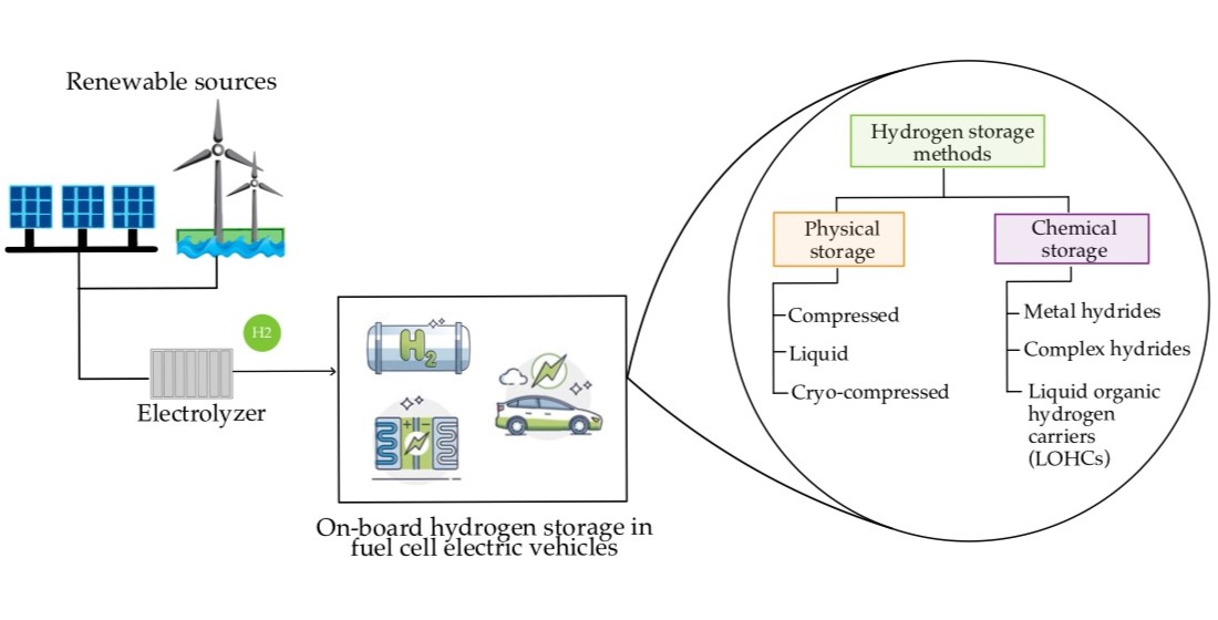
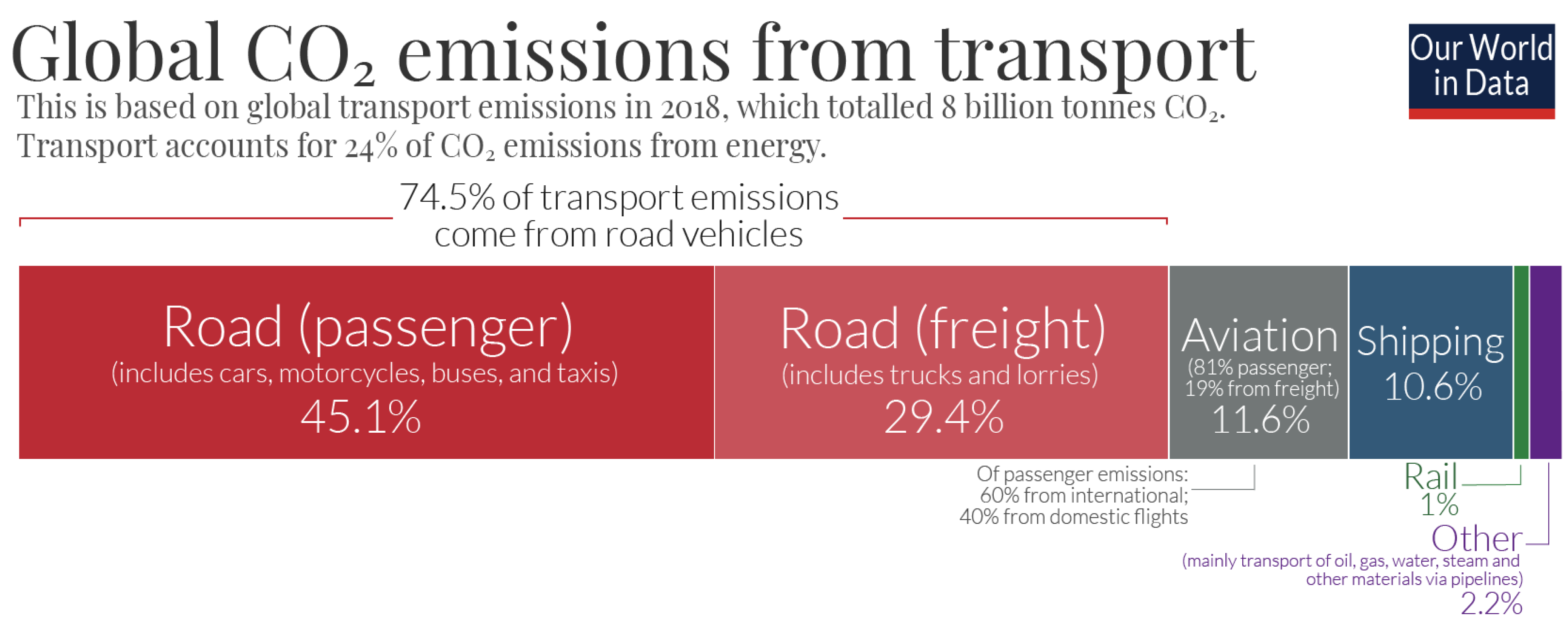
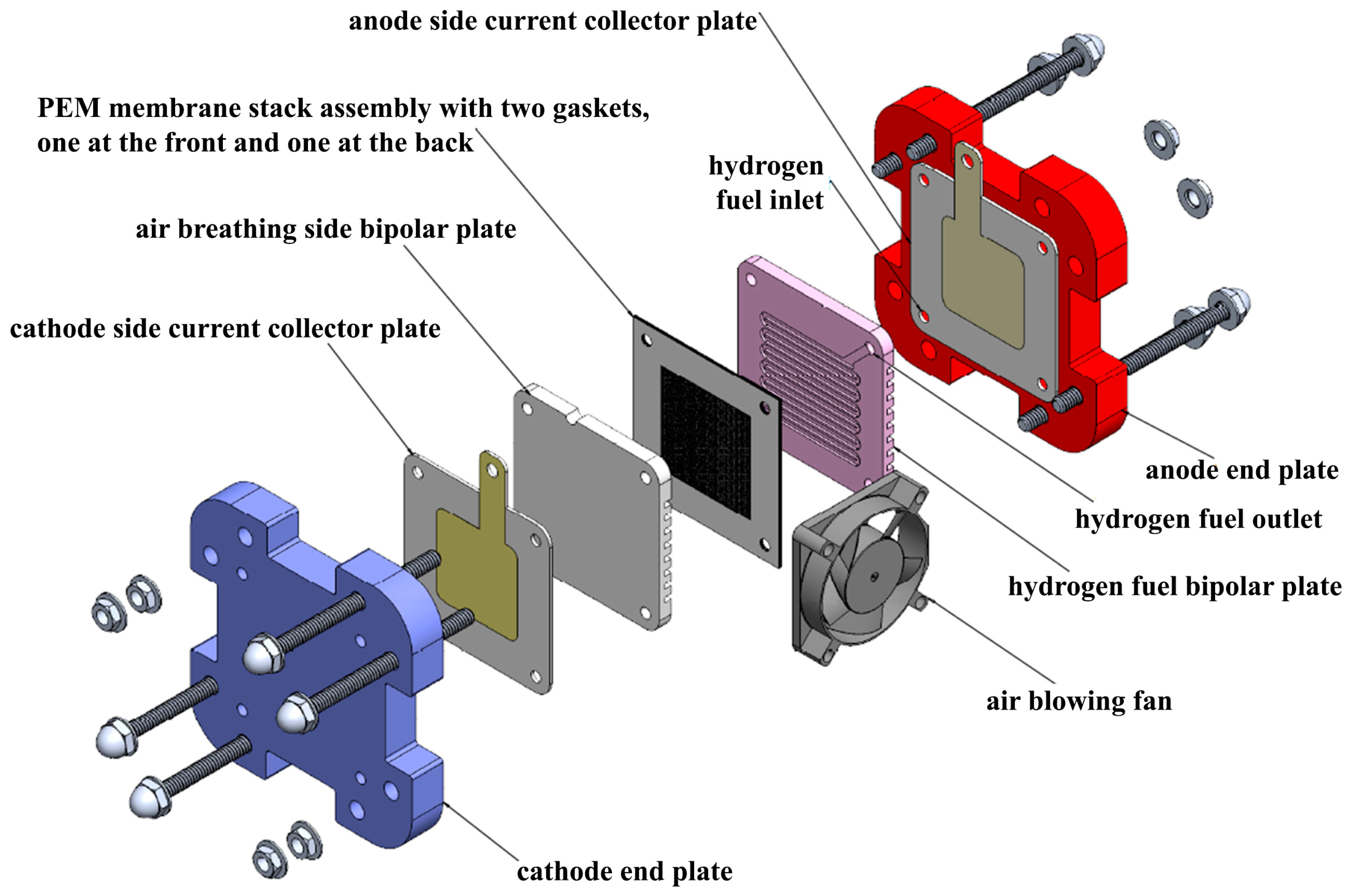
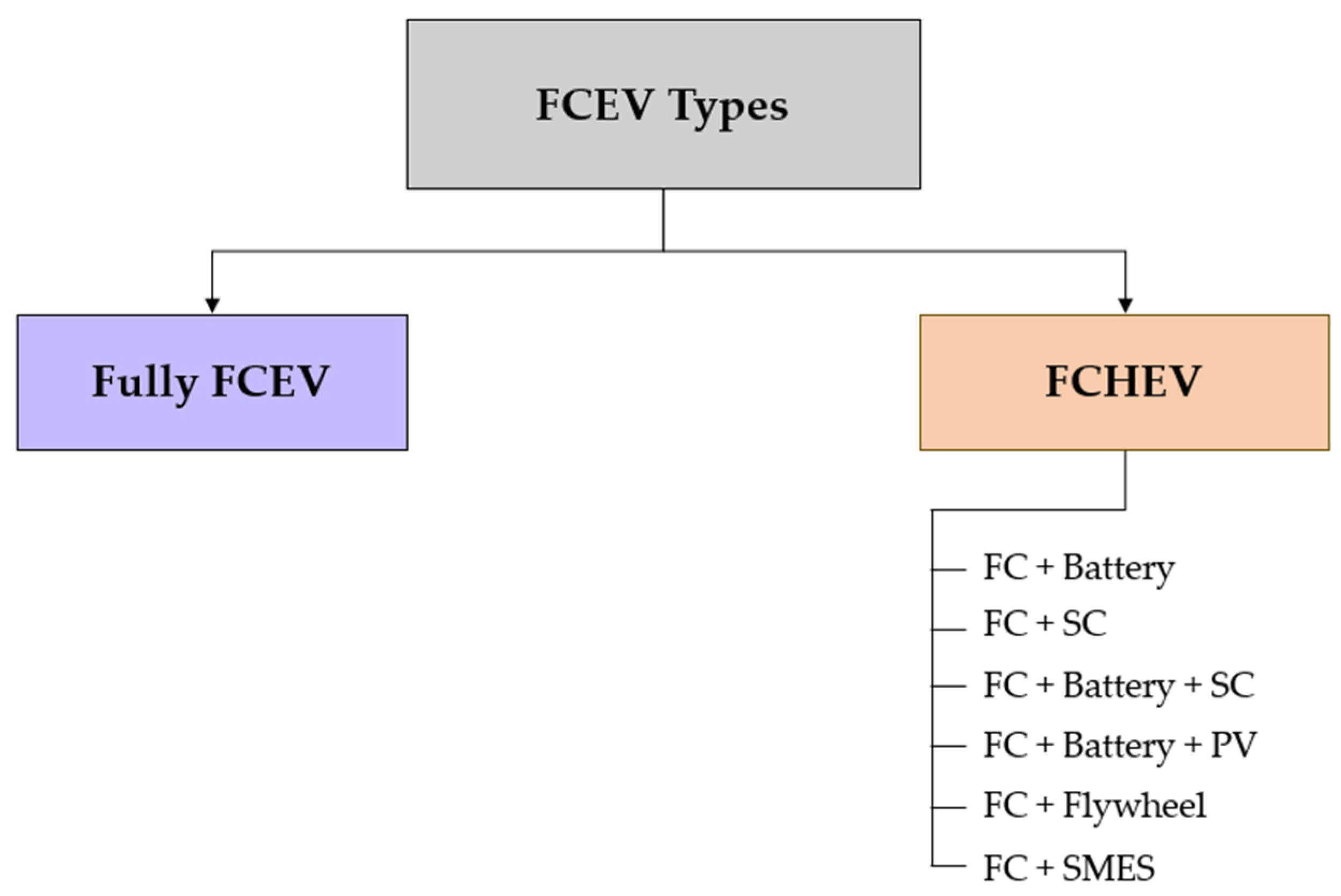
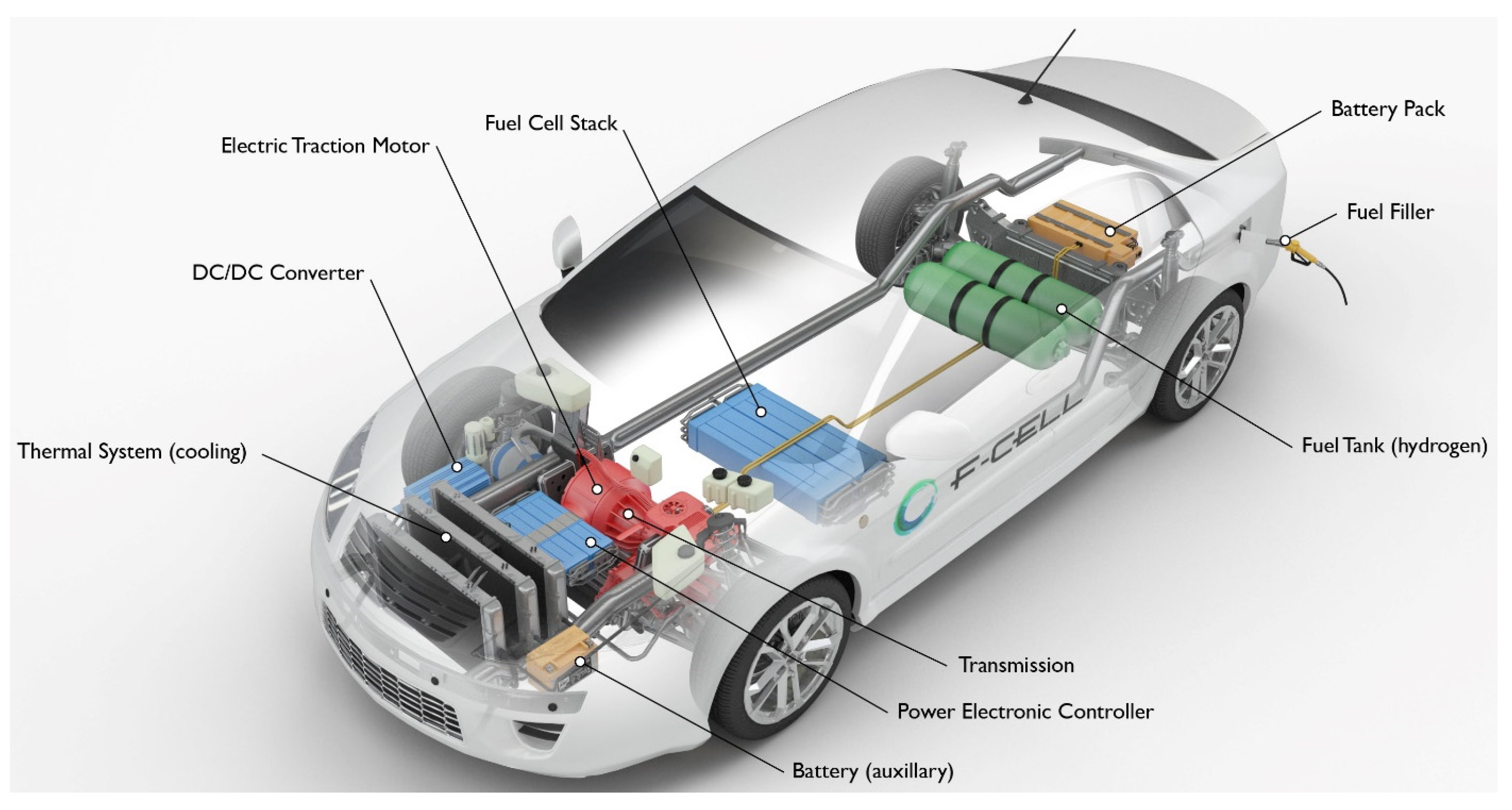
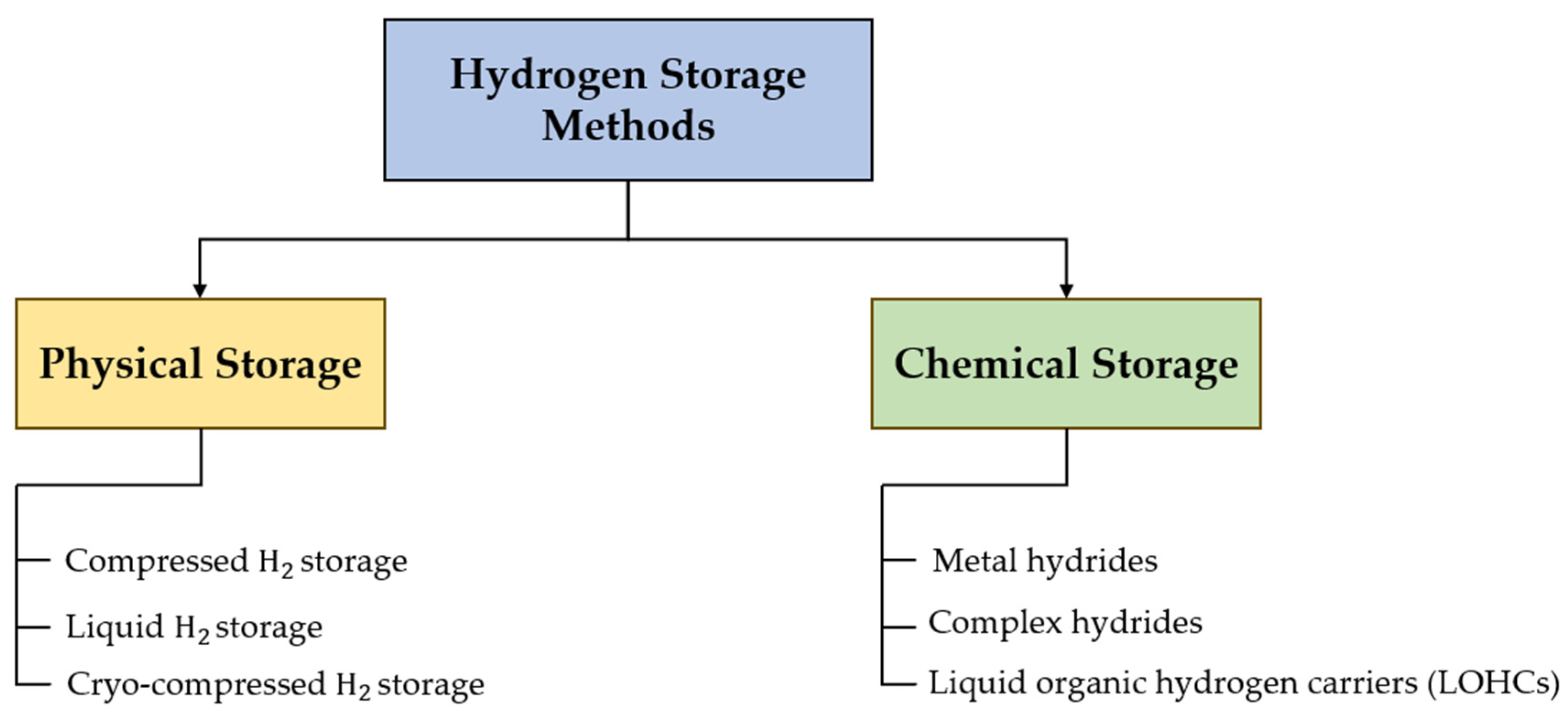
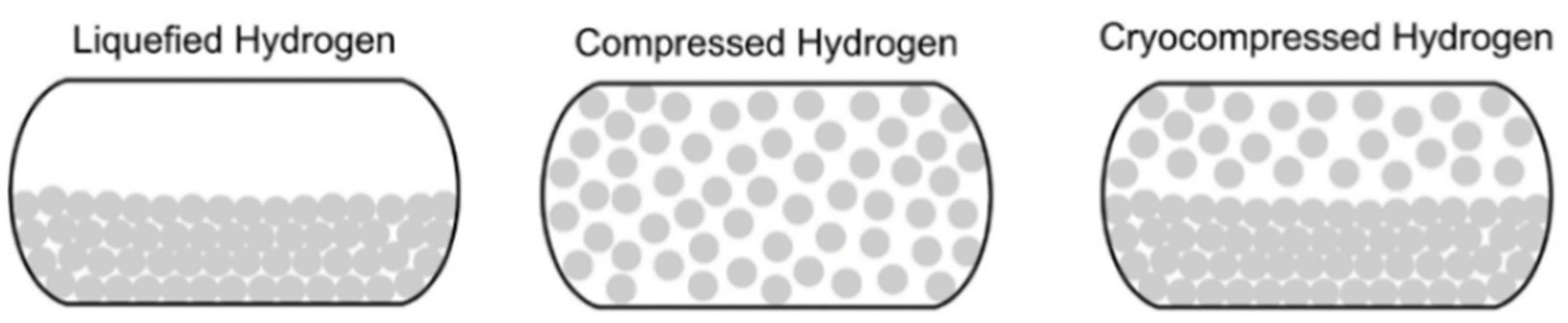
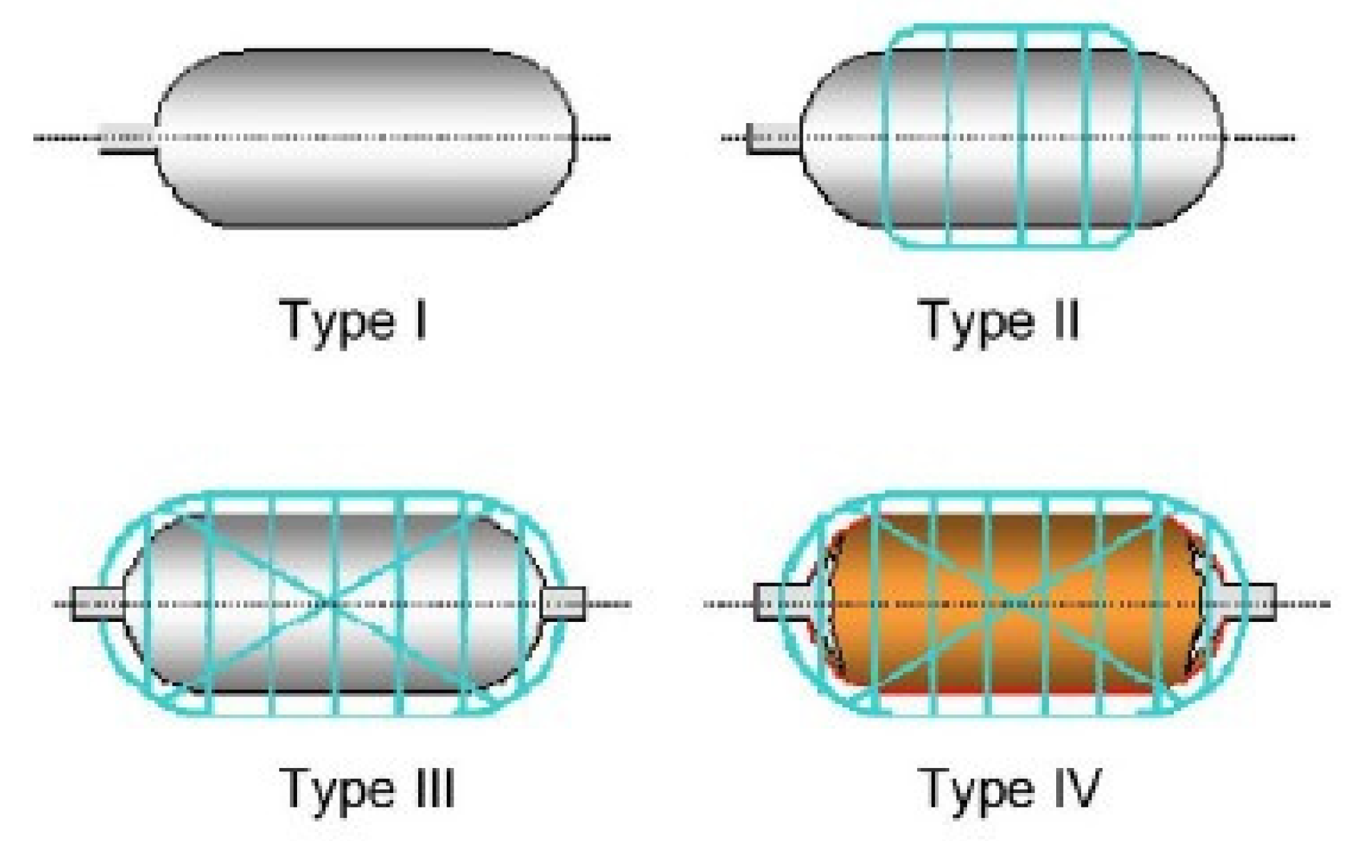
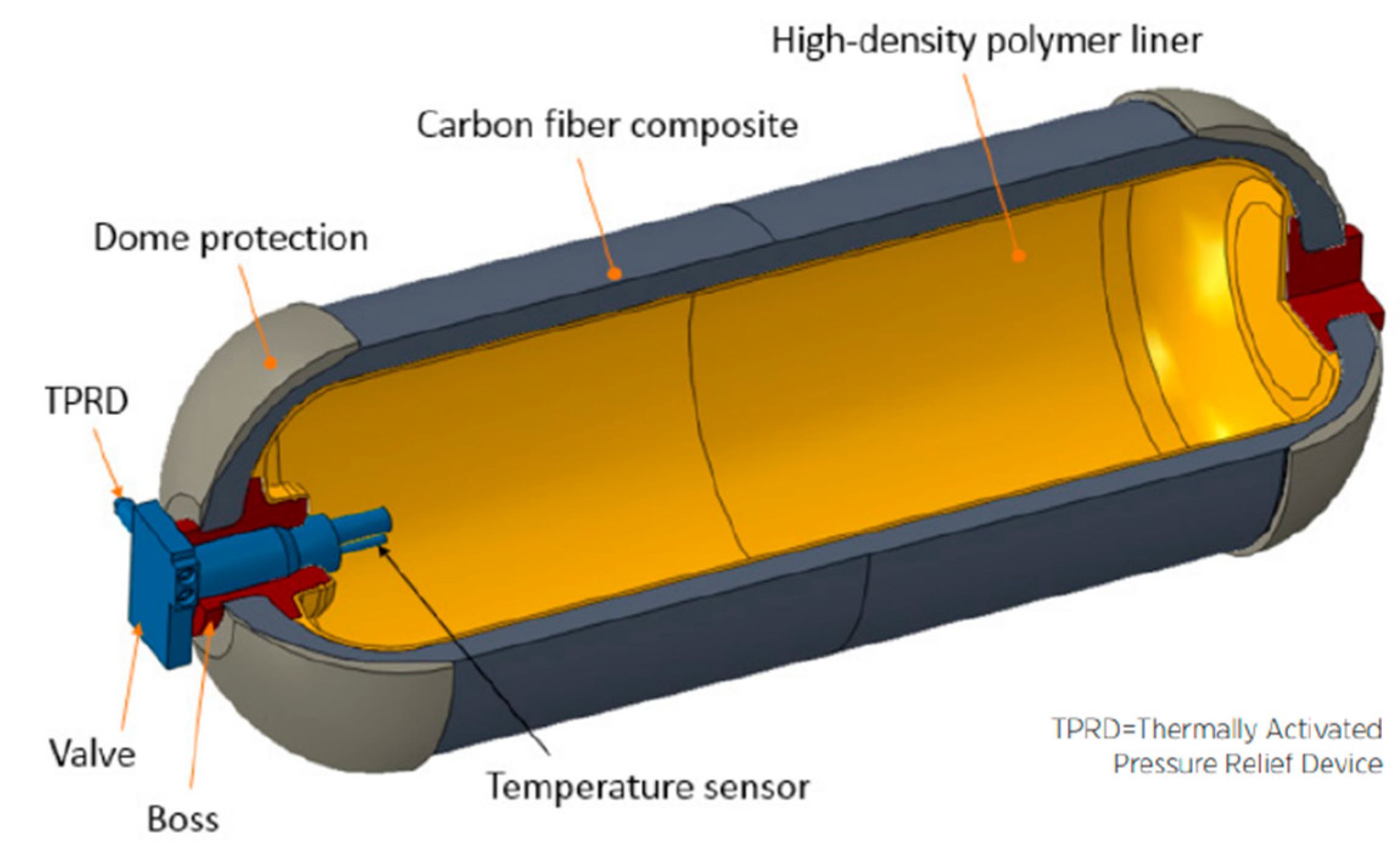
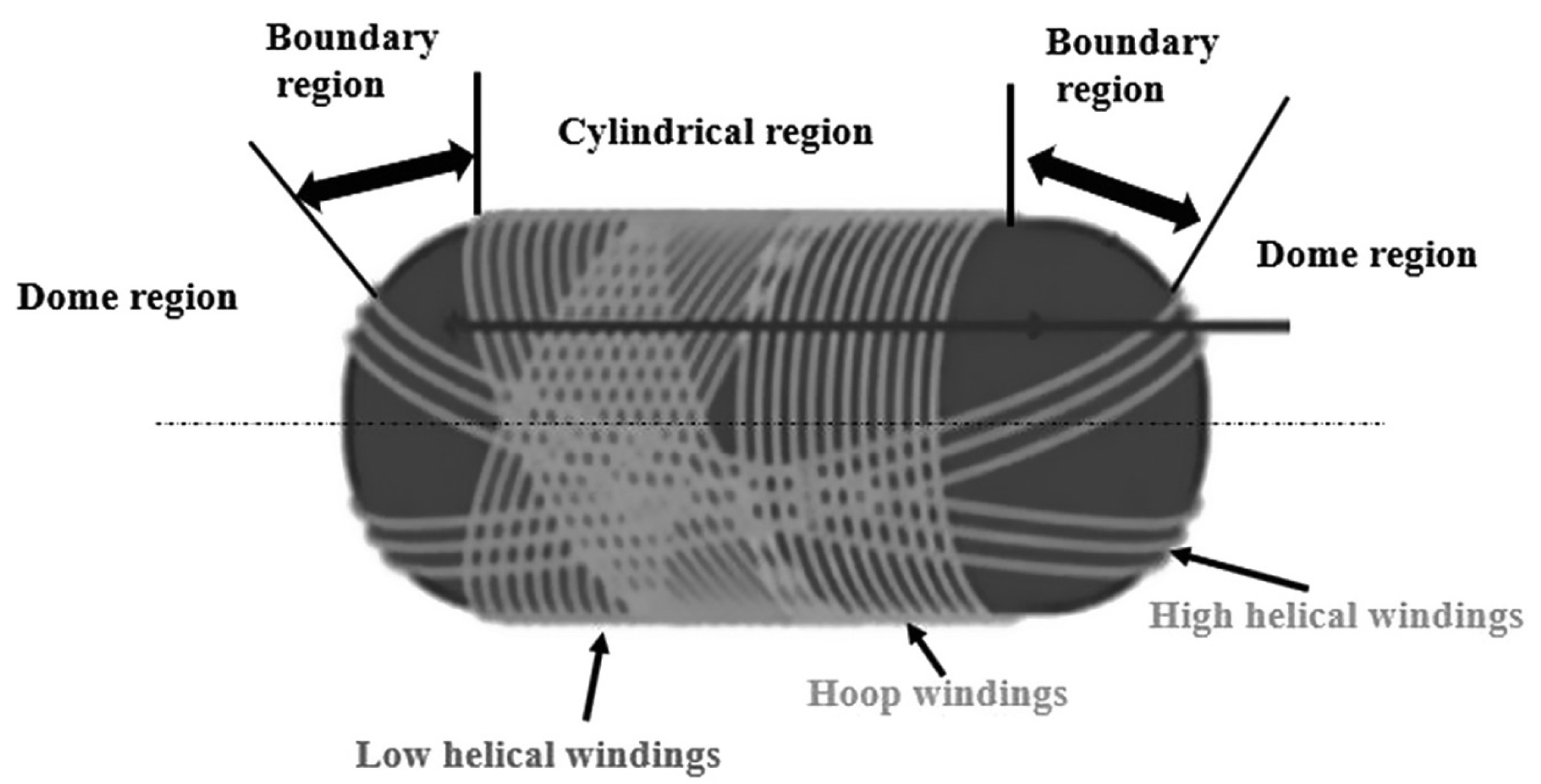
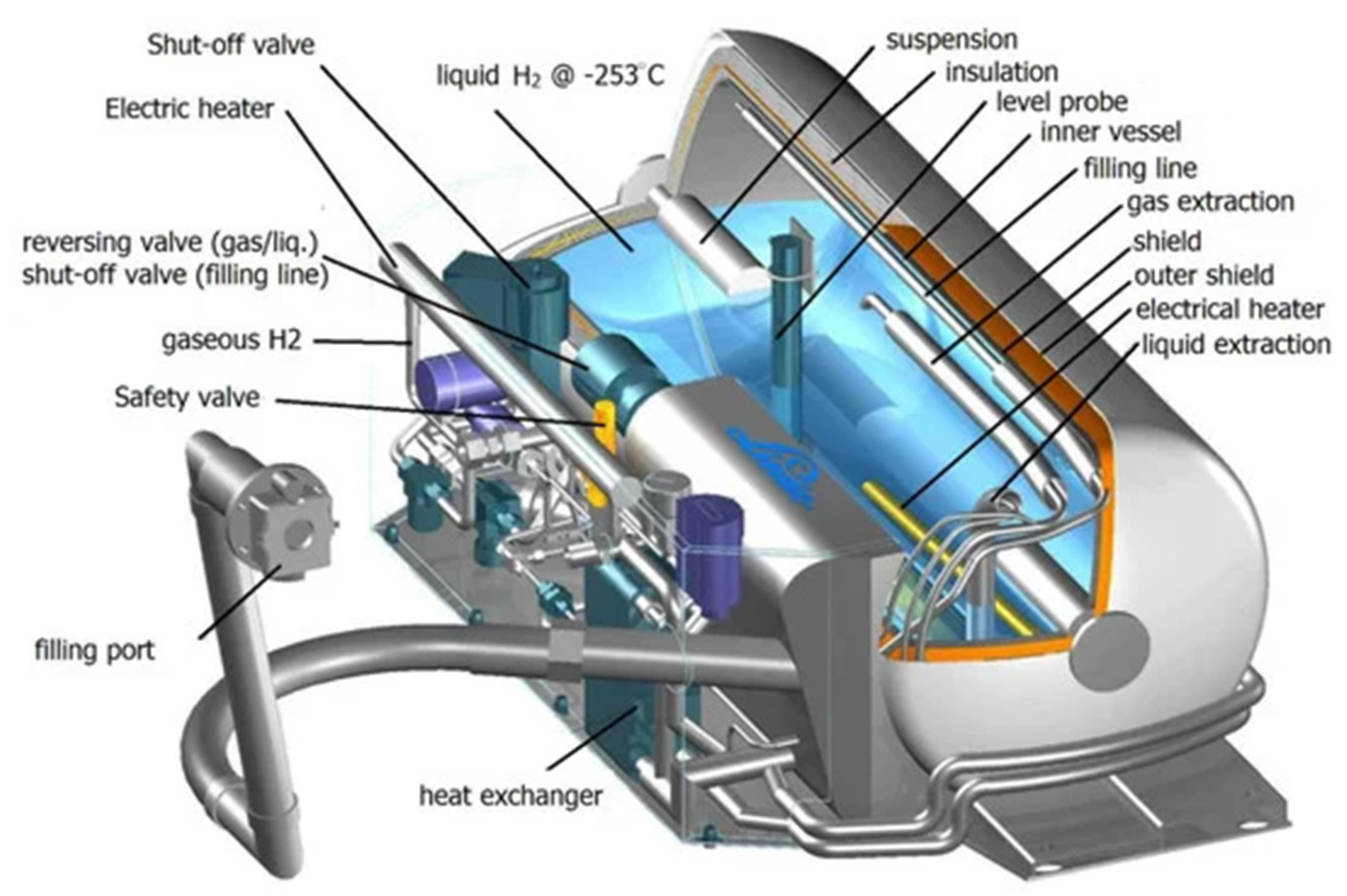
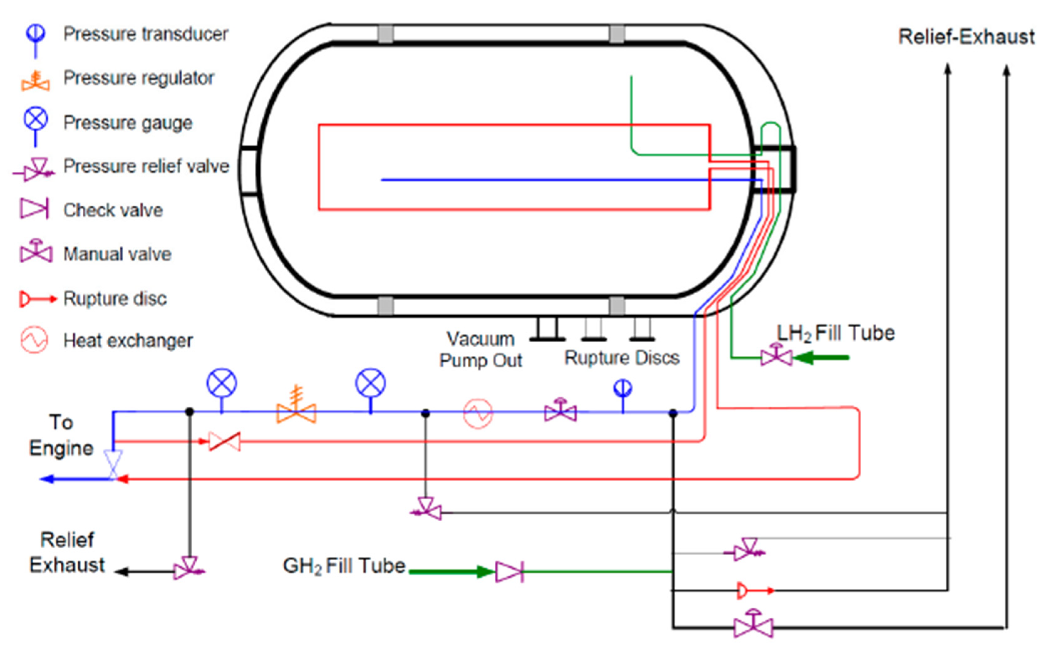
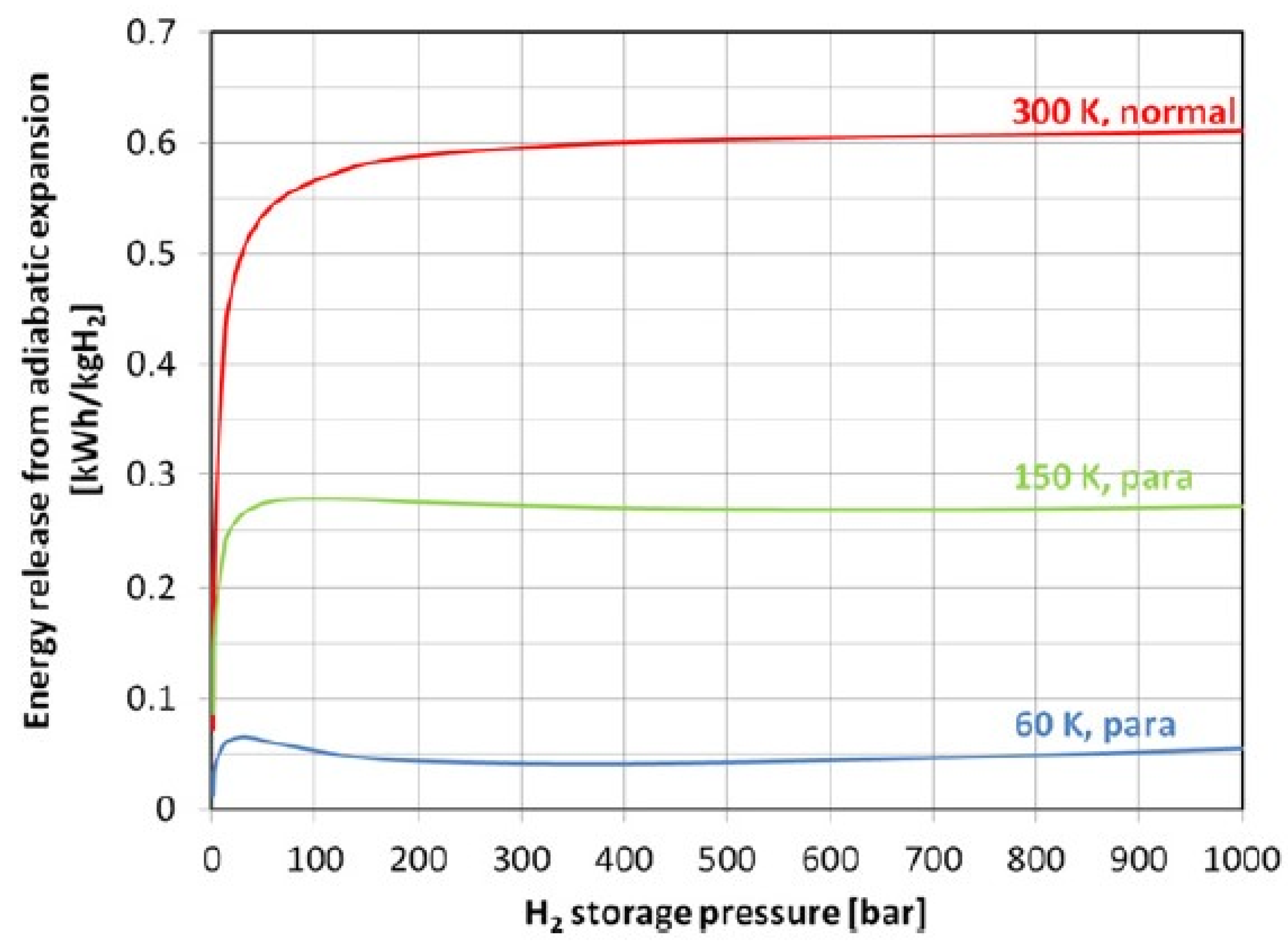
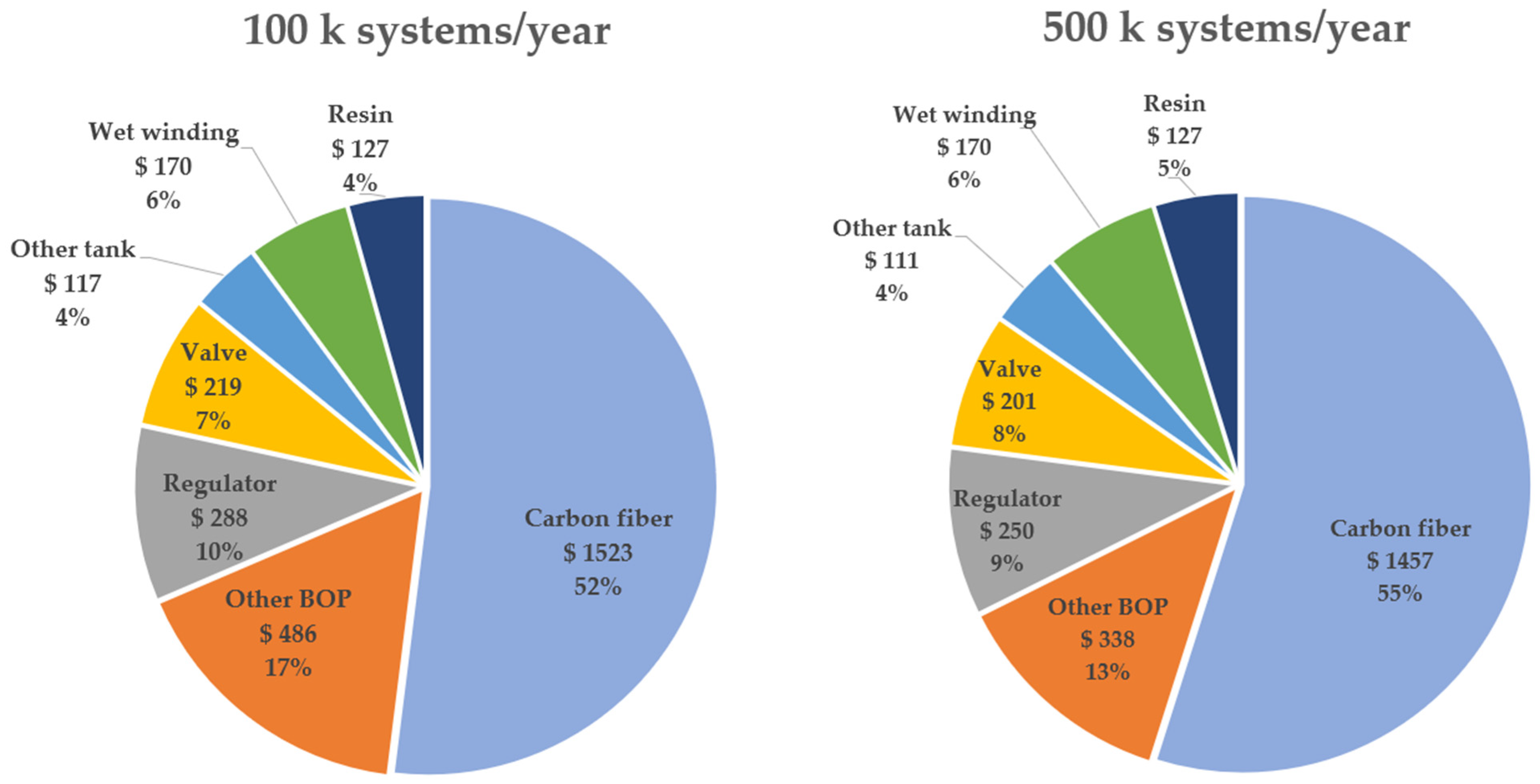
Table 1.
Comparison of fuel cells (FCs) used in fuel cell electric vehicles (FCEVs) [13]. Reprinted with permission from Elsevier.
Table 1.
Comparison of fuel cells (FCs) used in fuel cell electric vehicles (FCEVs) [13]. Reprinted with permission from Elsevier.
| Type | PEMFC | PAFC | AFC | SOFC | MCFC | DMFC |
|---|---|---|---|---|---|---|
| Advantages | -Low operating temperature -Fast charging, less corrosion, simplified electrolyte management | -Higher efficiency with CHP -Increased tolerance to fuel impurities | -Higher performance -Faster cathode reaction and start -Lower material cost -Low operating temperature | -Suitable for CHP -Higher efficiency -Fuel flexibility -Hybrid/gas turbine cycle | -Suitable for CHP -Higher efficiency -Fuel flexibility | -Low cost due to lack of fuel reformer |
| Disadvantages | -Expensive catalyst cost -Sensitive to impurities | -Expensive catalyst cost -Long start time | -Sensitive to CO2 levels in O2 and H2 | -High operation temperature, corrosion, and breakdown -Long start time | -High operation temperature -Long start -Power density | -Intermediates poisoning catalyst surface |
| Efficiency (%) | 40–60 | 40 | 60 | 60 | 50 | 40 |
| Fuel | Hydrogen | Hydrogen | Hydrogen | Hydrogen | Hydrogen | Methanol |
| Operating Temp. (°C) | <100 | 150–200 | 90–100 | 500–1000 | 600–700 | 60–200 |
| Cell Voltage (V) | 1.1 | 1.1 | 1 | 0.8–1 | 0.7–1 | 0.2–0.4 |
| Stack Power (kW) | 1–250 | 50–100 | 1–100 | 1–3000 | 300–3000 | 0.001–100 |
Table 2.
Pressure vessel materials, operating pressure, cost, and gravimetric density according to type [22].
Table 2.
Pressure vessel materials, operating pressure, cost, and gravimetric density according to type [22].
| Type | Materials | Typical Pressure (bar) | Cost ($/kg) | Gravimetric Density (wt.%) |
|---|---|---|---|---|
| I | All-metal construction | 300 | 83 | 1.7 |
| II | Mostly metal, composite wrapped in the hoop direction | 200 | 86 | 2.1 |
| III | Metal liner, full composite overwrap | 700 | 700 | 4.2 |
| IV | All composite construction | 700 | 633 | 5.7 (Toyota Mirai) |
Table 3.
Mechanical properties of materials for outer shell [6]. Reprinted with permission from CRC Press.
Table 3.
Mechanical properties of materials for outer shell [6]. Reprinted with permission from CRC Press.
| Fiber Type | Tensile Strength (MPa) | Tensile Modulus (GPa) | Density (g cm−3) | Specific Heat Capacity (J kg−1 K−1) | Thermal Conductivity (W m−1 K−1) | Composite Strength (MPa) |
|---|---|---|---|---|---|---|
| T300 carbon | 3530 | 230 | 1.76 | 777 | 10.5 | - |
| T700S carbon | 4900 | 230 | 1.80 | 752 | 9.6 | 2830 |
| T700G carbon | 4900 | 240 | 1.80 | 752 | 9.6 | - |
| T800 | 5880 | 294 | 1.80 | 752 | 11.3 | - |
| Flax | 8.25 | 23 | 1.45 | - | - | 345 |
| Basalt | 50 | 80 | 1.80 | - | - | 1600 |
Table 4.
Comparison of physical hydrogen storage methods for on-board vehicle applications.
| Storage Method | Type of Vessel | Operating Pressure (bar) | Operating Temperature (K) | Application | Advantages | Disadvantages |
|---|---|---|---|---|---|---|
| Compressed Hydrogen Storage | Type III Type IV | 700 | <350 | Small-scale storage | -Relatively low-cost and mature technology -Lightweight and compact | -Requires high-pressure tanks, leading to increased weight -Lower energy density compared to liquid hydrogen storage. |
| Liquid Hydrogen Storage | Type III | 1–3.5 | 20–40 | Large-scale storage | -High energy density -Can be stored at lower pressures compared to compressed hydrogen | -Cryogenic temperature requires specialized insulation -Requires significant space due to the need for insulation and larger storage tanks |
| Cryo-Compressed Hydrogen Storage | Type III Type IV | 350 | 20–40 | Large-scale storage | -Higher energy density compared to compressed hydrogen storage -Enables efficient storage with reduced losses | -Requires both cryogenic temperature and high-pressure vessels, increasing complexity and cost -Not commercially available |
Table 5.
H2 absorption/desorption properties of various complex hydrides [39]. Reprinted with permission from Elsevier.
Table 5.
H2 absorption/desorption properties of various complex hydrides [39]. Reprinted with permission from Elsevier.
| Complex Hydride | Temperature (K) | Pressure (MPa) | Hydrogen Storage Capacity (wt.%) |
|---|---|---|---|
| LiBH4 nanocomposite | Tdes: 573 | - | 6.5 |
| LiBH4 + LiBH3.75F0.25 | Tdes: 373 | 0.1 | 9.6 |
| LiBH4 + SiO2 | Tdes: 373 | 5.0 | 13.5 |
| NaAlH4 + 2.0 mol.% Ti(OBu)4 | Tabs: 423 Tdes: 433 | 11.4 | 4.0 |
| NaAlH4 + 1.0 mol.% TiCl3 | Tabs: 323–383 | - | 5.6 |
| NaAlH4 + 1.0 mol.% Ti | Tabs: 443 Tdes: 423 | 15.4 | 5.6 |
| NaAlH4 + 4.0 mol.% Ti | Tdes: 373 | - | 4.8 |
| NaAlH4 Ti(OBun)4 and Fe(OEt)2 | Tdes: 374 | 8.8 | 4.0 |
| NaAlH4 + 4.0 mol.% Ti | Tdes: 450 | 2.5 | 1.7 |
| Na3AlH6 + 2.0 mol.% TiCl3 | Tabs: 473 Tdes: 543 | 6.0 | 2.1 |
| Na3AlH6 + 2.0 mol.% Ti(OBu)4 | Tabs: 443 Tdes: 503 | 3.0 | 2.3 |
| NaAlH4 + porous carbon | Tdes: 673 | 10.0 | 7.0 |
| NaAlH4 + non-porous carbon | Tdes: 673 | 10.0 | 6.3 |
Table 6.
H2 storage technology readiness levels/ETP clean energy technology guide (adapted from [40]).
Table 6.
H2 storage technology readiness levels/ETP clean energy technology guide (adapted from [40]).
| Technology Readiness Level (TRL) | Storage Technology | Importance for Net-Zero Emissions |
|---|---|---|
| 11 | above-ground physical storage/ammonia storage | High |
| 11 | above-ground physical storage/pressure vessel | High |
| 9–10 | underground geological storage/salt caverns | High |
| 7–9 | above-ground physical storage/liquid hydrogen storage tank | High |
| 5 | underground geological storage/lined hard rock cavern | Moderate |
| 5 | underground geological storage/fast-cycling salt cavern | High |
| 4 | underground geological storage/depleted gas fields | High |
| 3–5 | materials-based storage/metal hydrides | Moderate |
| 3 | underground geological storage/aquifer | High |
| 2–3 | materials-based storage/adsorbents | Moderate |
Table 7.
Comparison between the achieved technical parameters for compressed hydrogen storage (Type III and Type IV vessels) and the performance targets set by the U.S. DOE for hydrogen storage systems in light-duty vehicles [41].
Table 7.
Comparison between the achieved technical parameters for compressed hydrogen storage (Type III and Type IV vessels) and the performance targets set by the U.S. DOE for hydrogen storage systems in light-duty vehicles [41].
| Performance and Cost Metric | Units | Type III Vessel | Type IV Vessel | DOE Targets | ||
|---|---|---|---|---|---|---|
| 350 bar | 700 bar | 2020 Target | 2025 Target | Ultimate Target | ||
| System gravimetric capacity | wt.% | 5.5 | 5.2 | 4.5 | 5.5 | 6.5 |
| System volumetric capacity | g-H2/L | 17.6 | 26.3 | 30 | 40 | 50 |
| Storage system cost | $/kWh | 15.4 | 18.7 | 10 | 9 | 8 |
| WTT efficiency (LHV) | % | 56.5 | 54.2 | 60 | 60 | 60 |
Table 8.
Specifications of commercially available FCEV models.
| Model | Technology/Fuel | Autonomy (km) | Power (HP) | Fuel Tank Capacity (kg) | Max Speed (km/h) | Price ($) | Country of Origin | Fuel Cell Type | Fuel Cell Power (kW) | Source |
|---|---|---|---|---|---|---|---|---|---|---|
| Toyota Mirai | Compressed/ Hydrogen | 647 | 182 | 5.6 | 300 | 50,000 | Japan | PEMFC | 114 | [44,45] |
| Hyundai NEXO | Compressed/ Hydrogen | 667 | 161 | 6.3 | 178 | 60,135 | South Korea | PEMFC | 95 | [46] |
| Honda Clarity | Compressed/ Hydrogen | 580 | 174 | 5.4 | 165 | 59,000 | Japan | PEMFC | 100 | [47,48,49] |
| Gumpert Nathalie | Methanol | 600–1200 | 540 | 65 L | 300 | 460,000 | Germany, China | DMFC | 130 | [50,51] |
| Changan DEEPAL SLo3 | Compressed/ Hydrogen | 730 | 218 | 5 | N/S | 100,000 | China | N/A | N/A | [52,53] |
| BMW iX5 Hydrogen | Compressed/ Hydrogen | 482 | 374 | 6 | 210 | 70,000 | Germany | PEMFC | N/A | [54,55] |
| Nissan e-NV200 SOFC e-BIO | Bio-Ethanol | 600 | N/S | 30 L | N/A | N/A | U.S., Brazil | SOFC | N/A | [56,57] |
Table 9.
Technical information of manufacturers of Type IV tanks for on-board applications.
| Iljin Hy Solutions [60] | Hexagon Purus [61] | Worthington Industries Inc. [62] | Quantum Fuel Systems [63] | Faurecia [64] | |
|---|---|---|---|---|---|
| Country of origin | South Korea | Norway | U.S. | U.S. | France |
| H2 capacity (kg) | 2.1 | 3.1 | 200–411 L | 3.1 | 2.75 |
| Max length (mm) | 900 | 1050 | N/A | 721 | 1110 |
| Max diameter (mm) | 350 | 440 | N/A | 504 | 350 |
| Service pressure (bar) | 700 | 700 | 700 | 700 | 700 |
| Container temperature (°C) | N/A | N/A | 80 | −40 to +82 | 80 |
| Tank weight (kg) | N/A | 59 | N/A | 51 | 37.5 |
| Further information | Hyundai NEXO tank supplier. More than 70,000 tanks have been sold by the end of 2021 | BMW, Robert Bosch GmbH, TesTneT Engineering, and Hexagon Purus partnership to develop innovative hydrogen storage systems for future FCEVs | Involved in the innovation of the latest technology integration within the hydrogen storage tank requirements in the market | Development programs with GM, Honda, Toyota, Suzuki, BMW, and DOE | Selected to partner on the hydrogen fuel cell to equip a Bavarian fleet of heavy-duty trucks provided by MAN |
Table 10.
Information overview of internal combustion engine vehicles (ICEVs), battery electric vehicles (BEVs), and fuel cell electric vehicles (FCEVs).
Table 10.
Information overview of internal combustion engine vehicles (ICEVs), battery electric vehicles (BEVs), and fuel cell electric vehicles (FCEVs).
| Internal Combustion Engine Vehicle | Battery Electric Vehicle | Fuel Cell Electric Vehicle | Source | |
|---|---|---|---|---|
| Overall efficiency (%) | 19 | 75 | 30 | [65] |
| Technology cost ($/kW) | 23.1 | 130 | 53 | [65] |
| Refueling cost ($/kWh) | 1.24 | 0.14–0.30 | 0.24 | [65] |
| Fuel consumption (at 100 km) | 6.85 L | 17.3 kWh | 1.05 kg | [66] |
| Range Autonomy (km) | 650 | 200–400 | up to 600 | [65] |
| Operating hours (h) | 10,000 | 7900 | 3000 | [67] |
| Costs per hour of Operation ($/h) | 0.58 | 3.91 | 2.62 | [67,68] |
| TTW CO2 Emissions | 203 (kg CO2/5 kg H2) | 101 (kg CO2/5 kg H2) | 0 (kg CO2/5 kg H2) |
Disclaimer/Publisher’s Note: The statements, opinions and data contained in all publications are solely those of the individual author(s) and contributor(s) and not of MDPI and/or the editor(s). MDPI and/or the editor(s) disclaim responsibility for any injury to people or property resulting from any ideas, methods, instructions or products referred to in the content. |
© 2023 by the authors. Licensee MDPI, Basel, Switzerland. This article is an open access article distributed under the terms and conditions of the Creative Commons Attribution (CC BY) license (https://creativecommons.org/licenses/by/4.0/).
Share and Cite
MDPI and ACS Style
Gómez, J.A.; Santos, D.M.F. The Status of On-Board Hydrogen Storage in Fuel Cell Electric Vehicles. Designs 2023, 7, 97. https://doi.org/10.3390/designs7040097
AMA Style
Gómez JA, Santos DMF. The Status of On-Board Hydrogen Storage in Fuel Cell Electric Vehicles. Designs. 2023; 7(4):97. https://doi.org/10.3390/designs7040097
Chicago/Turabian StyleGómez, Julián A., and Diogo M. F. Santos. 2023. "The Status of On-Board Hydrogen Storage in Fuel Cell Electric Vehicles" Designs 7, no. 4: 97. https://doi.org/10.3390/designs7040097