
Development and Performance Evaluation of Fibrous Pseudoplastic Quaternary Cement Systems for Aerial Additive Manufacturing

Department of Architecture & Civil Engineering, University of Bath, Bath BA2 7AY, UK
*
Author to whom correspondence should be addressed.
Designs 2023, 7(6), 137; https://doi.org/10.3390/designs7060137
Submission received: 28 October 2023
/
Revised: 17 November 2023
/
Accepted: 23 November 2023
/
Published: 27 November 2023
(This article belongs to the Special Issue Additive Manufacturing – Process Optimisation)
Abstract
:Aerial additive manufacturing (AAM) represents a paradigm shift in using unmanned aerial vehicles (UAVs, often called ‘drones’) in the construction industry, using self-powered and untethered UAVs to extrude structural cementitious material. This requires miniaturisation of the deposition system. Rheological properties and known hydration times are important material parameters. Calcium aluminate cement (CAC) systems can be advantageous over purely ordinary Portland cement (OPC) binders as they promote hydration and increase early strength. A quaternary OPC/pulverised fuel ash (PFA)/CAC/calcium sulphate (CS) system was combined with polyvinyl alcohol (PVA) fibres and pseudoplastic hydrocolloids to develop a novel AAM material for miniaturised deposition. CAC hydration is affected by environmental temperature. Intending material to be extruded in situ, mixes were tested at multiple temperatures. OPC/PFA/CAC/CS mixes with PVA fibres were successfully extruded with densities of ≈1700 kg/m, yield stresses of 1.1–1.3 kPa and a compressive strength of 25 MPa. Pseudoplastic OPC/PFA/CAC/CS quaternary cementitious systems are demonstrated to be viable for AAM, provided mixes are modified with retarders as temperature increases. This study can significantly impact industry by demonstrating structural material which can be extruded using UAVs in challenging or elevated in situ construction, reducing safety risks.
1. Introduction
The use of Additive Manufacturing (AM) methods in the construction industry is increasing [1], particularly with the use of 3D-printed concrete [2]. Construction-scale ground-based digital applications are realising structures via the layered extrusion of concrete [3,4], with controlled rheological properties [5] being of key importance while in the fresh state [6]. Layered extrusion can eliminate the need for traditional formwork [1], which can constitute up to 60% of the costs involved with building concrete structures [7]. Ground-based AM construction methods may consist of gantry frames [8,9,10,11], large robotic arms with multiple degrees of freedom [12,13] or coordinated robotic systems with multiple mobile agents [14,15]. There are numerous research groups and projects concerning AM in construction scenarios using cement-based material [16], where robotic agents can be utilised to realise cementitious-based structures both by layered extrusion but also by alternative methods such as spraying [17] or using temporary non-traditional formwork methods [18,19].
A key limitation of ground-based approaches, whether gantry frame or multiple-agent, is the building envelope being restricted by the dimensions and reach of the deposition equipment, particularly when considering height. Releasing AM from ground-based constraints allows the freedom to operate at a theoretically great height [20]. This freedom can be applied to construct a building taller than that capable of being constructed by a typical ground-based method, or the repair of tall structures—an inherently dangerous task in an industry with high numbers of falls-from-height-related serious accidents and fatalities [21].
The aerial additive manufacturing (AAM) project has demonstrated that multiple, coordinated, self-powered, non-tethered flying unmanned aerial vehicles (UAVs), each carrying and powering a small lightweight deposition device, can extrude cementitious pastes and mortars whilst following a pre-programmed, architecturally informed trajectory [22]. This represents a paradigm shift in the use of UAVs in the construction industry towards the potential for the construction of buildings in situ or elevated repair work to existing structures using multiple coordinated aerial agents. Previously, the use of UAVs in the construction sector was limited to surveillance [23] and data-gathering [24] applications.
Crucial material considerations for AM in construction are the choice of additives and rheology properties of materials while in the fresh state [25], particularly yield stress and recovery after shearing force has been applied [26]. The hydration or curing mechanism of a material is key [25], as, once deposition has occurred, it is desired for fresh material to harden as quickly as possible. Open time can be defined as the period of time following mixing in which fresh properties remain consistent [8] and the mix workable. Open time is a particularly important parameter for AAM since the mix has to remain fresh for a sufficient time period to allow for UAV loading, flight and deposition, with rapid hardening of material then being desired to mitigate post-extrusion deformation [27]. An in situ aerial deposition approach differs significantly from ground-based or ground-powered AM applications, requiring lower-density cementitious mixes and miniaturised, lighter deposition devices appropriate for carriage by self-powered UAVs [22,27].
Binders based upon ordinary Portland cement (OPC) alone possess an open time of ≈2 h [28] and hydration time of 12+ h, which can be considered too long for AM [29]. Ternary binder systems can achieve faster setting than a binder consisting solely of OPC [30].
Calcium aluminate cement (CAC) is an option for reducing open times and promoting hydration, but presents two challenges. Firstly, for AM applications, material must be able to flow through a miniature deposition system prior to accelerated exothermic CAC hydration reactions with a rapid rate of heat evolution [31,32] taking place following deposition. RMAs can be used to influence the rheology of fresh material mixes [33] and pseudoplastic RMAs such as hydroxyethyl methyl cellulose (HEMC) can possess retardation properties [34]. However, combining CAC with OPC promotes early ettringite formation and a flash-set [35]. Hydration times are directly affected by variations in quantities of OPC and CAC [36] and environmental temperature [37], with high temperatures promoting rapid hydration [38]. Therefore, acceleration (at low environmental temperatures) and retardation (at high temperatures) may need to be considered in OPC/PFA/CAC/CS binder-based mix formulations.
The second consideration is the status and reputation of CAC systems due to the historically misunderstood conversion reaction [39,40] leading to the potential reduction in strength to a stable long-term level when material experiences temperatures higher than those experienced during formation [32]. In CAC at low and intermediate temperatures, metastable hydrates CAH and CAH form, whereas at higher temperatures stable hydrates CAH and AH (alumina gel) are formed. Material formed at low temperatures (<20 °C) possesses higher early strength, but the metastable hydrates convert to CAH and AH over time as temperature rises, leading to a relatively reduced longer term strength, which must be considered during design [38]. Conversion can take days to complete at higher temperatures of ≈60 °C [32], but may take years at ambient 20 °C temperatures [41,42]. Pure CAC systems were omitted from design standards for reinforced and pre-stressed structural concrete following roof and ceiling beam failures in the late 20th century, despite extensive inspections, revealing the vast minority of cases to be linked to loss of strength due to conversion. Instead, poorly detailed design or low-quality aggregates were determined as primary causes of collapse [32]. However, CAC has remained an important material for ground anchoring [43] and rapid repair work [31,36], particularly in marine and tidal environments [40], roads and airfield runways [44]. In OPC-rich blended cement systems such as OPC/CAC/CS, the smaller amount of CAC typically used does not lead to the formation of the metastable hydrates, and thus conversion would not occur [31]. It has also been shown that metastable hydrates do not form in a pulverised fuel ash (PFA)/CAC/CS ternary system [42].
This study investigates the feasibility of adding calcium aluminate cement (CAC) and calcium sulphate (CS) to OPC and PFA for AAM through the development of a novel fibrous quaternary OPC/PFA/CAC/CS binder system augmented with rheology-modifying admixtures (RMA) to promote ease of extrusion and rapid curing following extrusion. CAC acts as an accelerator [45], promoting early strength [40] and hardening of material, which would be an asset once material has passed through the deposition system to prevent deformation prior to hardening [46] due to either self-weight, trajectory imperfection or subsequently deposited layers. Fibres were required to add ductility to cured material and mitigate crack propagation, and pseudoplastic properties were desired to promote liquid-like properties in fresh material mixes while under stress within the miniature deposition system and solid-like properties with a significant increase in viscosity once deposited. PFA, consisting of spherical particles, is known to enhance workability (flow of fresh material) [47]. When added to OPC/CAC, CS anhydrite has been shown to further promote ettringite development [42] and stability [48], along with early strength [39]. In an OPC-rich quaternary OPC/PFA/CAC/CS binder system developed for AAM, the conversion reaction would not be expected to occur. Polyvinyl alcohol (PVA) fibres have been shown to be durable within the cementitious alkaline environment [49] and chopped PVA fibres have been included as constituents in formulated OPC/PFA/CAC/CS-based fresh mixes in this study. Individual 12 mm length fibres are appropriate additions in AAM mixes in low volumes [50], preventing brittle failure, resisting crack propagation and decreasing shrinkage in hydrated cementitious material. The feasibility of incorporating a fibre volume (FV) of 2%, typical for cementitious composites [51], is investigated for AAM. To suitably modify the rheology properties of fresh mixes, this study used a combination of HEMC and xanthan gum (XG), which have both been demonstrated to be effective RMA solutions for a cementitious material suitable for AAM [22].
Fresh mixes were subject to deformation, rheology and calorimetry tests, and hydrated mixes were tested for mechanical properties. Fresh mixes were extruded both autonomously using a miniature deposition device, and by hand, to analyse workability (defined in this study as the ability of a fresh material to be processed by a miniature deposition device) and buildability (defined in this study as the ability of the material to retain shape following extrusion and resist excessive deformation due to subsequently deposited layers). The potential applications of AAM with a quaternary binder system are discussed. This study presents the first time that CAC has been used in an AAM application, which is in itself a unique method of AM in construction, being the only study to use self-powered, untethered multiple UAV agents.
2. Materials and Methodology
AAM is intended for in situ applications, which, naturally, are subject to climatic and seasonal variation. With the use of CAC, it is to be expected that material mixes will perform differently in different environmental conditions and with differing water temperatures. The strategy undertaken in this study was that mixes should be adaptable to changeable climatic conditions, rather than to try and exert control over the environmental temperature or heat (or cool) the water used in order to satisfy the requirements of a singular mix.
Tests carried out involved the rheological properties of the fresh material mixes (yield stress, viscosity, complex modulus), extrudability through the AAM miniature deposition system and the power and force required to extrude, retard and deform fresh mixes, the calorimetry curves of fresh mixes and the mechanical strength of hydrated mixes. Tests were performed on five developed mixes, termed 1–5. Mix formulation was carried out in temperatures of 14.5 °C ± 2 °C with a water temperature of 15.5 °C ± 2 °C. It was decided to undertake mix formulation in moderate temperatures representing an external, in situ application scenario, keeping in mind that accelerating agents added in cooler environments will be substituted for retardation agents in warmer seasonal temperatures. Laboratory tests were conducted in internal shared facilities with the ambient temperature of the laboratory environment specified in each test subsection.
Mix 1, without CAC and CS, was based upon a material mix which had had been previously successfully extruded using a UAV in flight, carrying the material in a miniature deposition device [22]. Mixes 2–5 were OPC-rich OPC/PFA/CAC/CS quaternary binder-based mixes formulated to determine suitability for AAM; the formulations presented in this study feature a range of constituents and mixes which were presented and taken forward for further tests by trialling the fresh mixes with the miniature deposition device in order to confirm that they could be viably processed by the device while carried and powered by a flying UAV. It was intended for the formulations and constituents of mixes 2–5 to differ, in order to evaluate the effects and properties of cured mixes once they had all satisfied the base requirement of being viable for AAM deposition while fresh. Mix 1 essentially acted as a control mix, against which mixes 2–5 containing CAC and CS could be compared and evaluated.
This study used CEM I 42.5 R Portland cement (Dragon Alfa Cements Ltd., Gloucester, UK) with a particle size of 5–30 m and bulk density of ≈1400–1500 kg/m, as the base binding constituent. The chemical composition of the CEM I, as determined by Rietveld quantitative phase analysis, is shown in Table 1.
The constituents and fresh densities of the five mixes are summarised in the process flowchart (Figure 1) and shown in detail by kg/m in Table 2 along with specifications, suppliers, fibre volumes (FV) and sand/binder (S/B), water/binder (W/B), accelerator binder (A/B) and retarder/binder (R/B) ratios. The superplasticiser (SP, supplied by Imerys, UK) was sulphonated melamine-based, which works via electrostatic repulsion [32], which is the same mechanism as sulphonated napthalene-based superplasticisers which have been shown to promote shear thinning in slurries [52]. The 350 m diameter (D) PVA fibres (supplied by Flint, London, UK) were 12 mm in length. The sand featured smoothed, sub-rounded particles to aid workability through a miniaturised deposition device.
The EN 450 N grade type-F pulverised fuel ash (PFA) (supplied by Cemex, Bristol, UK), had a bulk density of 800–1000 kg/m and particle size < 45 m. The smooth-particle sand (supplied by British Playsand, UK, product number 365/0574), was kiln dried at a temperature of 105 °C prior to use for a period of twenty-four hours and possessed a dry bulk density of 1450 kg/m. The Ternal SE CAC (supplied by Imerys, UK Division) has a bulk density of 1100–1300 kg/m. The Ground Gypsum Superfine White CS (supplied by Industrial Plasters, Chippenham, UK) has a bulk density of 900–1100 kg/m.
Mix 1 had an open time of ≈2 h, whilst mixes 2–5 had open times of 20–25 min in temperatures of 14.5 °C. It was anticipated that with increased rates of hydration in warmer temperatures above 15 °C, the accelerator quantities shown in Table 2 may need to be reduced, or even removed and substituted by suitable quantities of retarding agent. The accelerating agent used was Peramin AXL80 (supplied by Imerys, Dorset, UK) and the retarders were citric acid and tartaric acid (supplied by Sigma-Aldrich, Dorset, UK). HEMC MKX6000 was supplied by Dow Chemicals, UK Division, and xanthan gum by Minerals-Water, Purfleet, UK.
With the exception of water and foaming agent (supplied by EAB Associates, Manchester, UK), all mix constituents were of a dry, powdered consistency. Mixes were created by hand-mixing dry constituents and then adding water. Automated planetary motion mixing took place for three thirty-second periods, interspersed with manual gathering of constituents. If used, foam was then added to the slurry and integrated with two periods of thirty-second planetary motion mixing interspersed with manual gathering and mixing. Each fresh mix was subjected to a ten-second period of automated vibration to create a slurry ready for loading into the deposition device.
The AAM project miniature deposition device [22] with a 12 V DC motor suitable for UAV carriage is shown in Figure 2. Material is pushed through the cartridge by a plunger attached to a threaded rod. The device component, which determined mix formulation to the greatest extent, was the 560 mm length of flexible plastic tubing connecting the tip of the material cartridge to the 8 mm diameter nozzle. In Figure 2, the nozzle is depicted as being held and directed by a four degrees of freedom (DOF) Dobot magician robotic arm (Dobot, Shenzhen, China), representing the role performed by a stabilising delta arm robot, which attaches to the base of a UAV to guide, and provides lateral stability to the nozzle [22]. During the extrusion experiments carried out in this study, nozzle movement was also controlled by hand.
2.1. Fresh Mix Extrusion
The five mixes were all tested for AAM suitability using a 310 mL cartridge capacity deposition device, shown in Figure 2, with mixes manufactured in environmental temperatures of 14.5 °C ± 2 °C with a potable water temperature of 15.5 °C ± 2 °C. It takes approximately 4 min for the deposition device to extrude a cartridge of material. Therefore, the aim of autonomous deposition is to commence extrusion 15–20 min following mixing (to allow for material loading into the cartridge and cartridge loading into the deposition device attached to the UAV) and complete extrusion at 20–25 min following mixing, at which point rapid hardening in the deposited material is desirable.
Deposition device tests extruded material in a trajectory consisting of alternate layers of three parallel lines and a peano curve layer, which has been demonstrated previously in Zhang et al., 2022 [22], in order to observe how extruded material may deform both in compression and sagging. The alternating layer trajectory approach was chosen for two reasons. Firstly, it had proved to have an effective compressive strength to amount of material used ratio when compared to alternative wall designs, including printing immediately adjacent layers to form a solid wall. Secondly, it was developed with the intention of extrusion by an untethered, self-powered autonomous flying UAV, which requires a stabilising delta robot to steady the extrusion nozzle and mitigate against enforced lateral deviation from programmed trajectories due to air movements and propeller thrust. Current UAV lateral deviations from programmed trajectories are within 1 mm, and this will improve with continuing development, but the alternating layer approach mitigates against the risk of an imprecise deposition of up to a millimetre of a layer on top of a previous layer of identical trajectory. Additional hand extrusions were also performed to examine other potential AAM applications of the material mixes, including printing directly on to a vertical surface and printing on support material, which was subsequently removed, to create a bespoke structure. A further area of AAM development is the ability for a UAV to land at elevation onto a vertical surface and extrude material, with the material in this study being demonstrated to be able to adhere to an inclined or vertical plane and be suitable for such potential applications of precision construction repair work in dangerous or elevated locations.
2.2. Power and Force Requirements
The force requirement tests for fresh mixes were conducted in the internal laboratory ambient temperature conditions of 20 °C ± 2 °C, with a potable water temperature of 17.5 °C ± 1 °C. Cartridges full of freshly mixed material were placed vertically upon an Instron Universal 2630-120/305632 device (Instron, High Wycombe, UK) and a rod was pushed down upon a plunger at a rate of 17 mm/min to simulate the movement of the deposition device plunger. The force required to process the material at this rate of displacement was analysed. While the deposition device processed the mixes, the current required to push the material through the tubing as indicated by the 12 V power supply was also recorded.
2.3. Fresh Mix Rheological Properties
To quantify the rheological properties of the fresh mixes (and how these are affected by temperature), flow and oscillation tests were conducted using upper and lower plate temperatures of 7 °C, 14.5 °C and 22 °C. A TA DHR-2 rheometer (TA Instruments, Hertfordshire, UK) was used to conduct the tests with a 25 mm diameter flat upper geometry plate and flat 40 mm diameter lower plate. Ambient internal laboratory temperatures were 20 °C ± 1 °C and laboratory potable water temperature was 17.5 °C ± 1 °C.
Flow tests were shear stress-controlled using linear stress ramps ranging from 300–6000 Pa and 900–50,000 Pa. Tests were designed to obtain yield stress and viscosity, which quantify flow and flow velocity, respectively [53]. Tests were repeated at regular time intervals during the open time of the fresh mixes, during which material was exposed to environmental temperatures prior to testing.
Oscillation tests were conducted over a period of 2000 s (covering the open time of all mixes) and were controlled using an angular displacement of 5 × 10 radians with frequency maintained at 1 Hz. Using the elastic modulus G, viscous modulus G and phase angle data, the complex modulus G*, quantifying the stiffness of the fresh material, can be calculated as:
where (radians) is:
2.4. Fresh Mix Calorimetry
All mixes were placed in a Calmetrix I-Cal 4000 isothermal calorimeter (Calmetrix, Boston, MA, USA) immediately following mixing and vibration. Each mix was tested three times, with the chamber temperature maintained at 7 °C, 14.5 °C and 22 °C, respectively. Tests were carried out over a period of forty-eight hours to analyse how the energy transferred and rate of heat evolution differed with constituent and temperature change during the hydration process. Ambient laboratory temperatures were 20 °C ± 1 °C and laboratory potable water temperature was 17.5 °C ± 1 °C.
2.5. Fresh Mix Deformation
Freshly extruded beads of material mixes were subjected to deformation on an Instron Universal 2630-120/305632 device. Ambient laboratory temperatures were 20 °C ± 2 °C and laboratory potable water temperature was 17.5 °C ± 1 °C. Freshly extruded beads of material 8 mm in diameter and 80 mm in length were placed between two steel plates and compressed at a rate of 2 mm/min to simulate an extruded layer of material being subjected to compressive loading from subsequent layers deposited on top. Extruded beads were tested at five minute intervals over the open time period of the material.
2.6. Hydrated Mix Mechanical Properties and Method of Flexural Failure
Fresh mixes were poured into 160 mm × 40 mm × 40 mm moulds in accordance with British Standard BS EN 1015-11:1999 [54] and mechanically vibrated. The density was calculated for each prism prior to testing. Flexural and compressive strength tests were carried out on the hydrated prisms using an Instron Universal 2630-120/305632 device to obtain an indication of 1-day and 28-day strength values. Ambient laboratory temperatures were 20 °C ± 2 °C and laboratory potable water temperature was 17.5 °C ± 1 °C. Four-point bending flexural tests were in accordance with British Standard BS EN 12390-5:2009 [55]. Compression tests were subsequently conducted in line with British Standard BS EN 1015-11:1999 [54].
2.7. Retardation and Further Rheological Tests
To further investigate the differing open times of the material arising through changes of ambient temperature, mix 2—retarder/binder (R/B) ratio 0.12%—was modified with the addition of retardation agents with R/B quantities of 0.52%, 0.78%, 1.04% and 1.56%. Both citric acid and tartaric acid were investigated as retarders independently. Citric acid is established as a commercial retarding agent for CAC systems, working by the mechanism of precipitation of gel-coatings around cement grains [43], thus inhibiting the formation of ettringite [30]. Tartaric acid possesses an affinity for aluminate surfaces and is also known to inhibit ettringite formation [56].
Further oscillation and flow rheology tests were undertaken. Ambient laboratory temperatures were 20 °C ± 2 °C and laboratory potable water temperatures were 17.5 °C ± 1 °C. Mix 2, as shown in Table 2, was modified with additional quantities of either citric or tartaric acid, and tested on the rheometer for the duration of the material open time. Flow tests were conducted at five-minute intervals following mixing, with the fresh mix subject to ambient environmental air. Oscillation tests were conducted with the retarded fresh material kept within the plates of the rheometer for the test duration.
3. Results
In the results section the following colour coding has been assigned to the mixes: blue (1), green (2), yellow (3), magenta (4) and grey-black (5).
3.1. Fresh Mix Extrusion
All five mixes were extruded by the 310 mL capacity deposition device when the mixes were manufactured in environmental temperatures of 14.5 °C ± 2 °C with a potable water temperature of 15.5 °C ± 2 °C. Figure 3 shows a range of extrusions both by hand and deposition device.
Printed by hand, Figure 3a shows a latticed dome structure consisting of mixes 2 and 3 printed upon supporting material, which was subsequently removed to prove the structure to be self-supporting (Figure 3b). A U-shaped 8-layered extrusion featuring mixes 1, 2 and 4 was deposited on a vertical surface (Figure 3c,d). Three layers of fresh material can be printed vertically in immediate succession during the open time of the material. The fourth and subsequent layers must take place after the material has hardened—Figure 3d shows three fresh layers extruded upon hardened previous layers.
Using the deposition device, Figure 3e shows alternating layers of three straight parallel lines and a peano curve shape using (top to bottom) mixes 2, 5 and 3. The straight line middle layer of the less dense, higher foam content mix 5 shows the most sagging, while mixes 2 and 3 exhibit minimal deformation.
Based on autonomous deposition success at lower temperatures, the open time of mix 1 is considered to be 2 h, while the open times of mixes 2–5 (as formulated in Table 2) are considered to be a working maximum of 25 min. Realistically, the quickest time that a deposition device can commence extrusion of material following mixing and vibration is 15 min and, at ≥14.5 °C, mixes 2–5 can become too stiff for extrusion within this time.
3.2. Power and Force Requirements
With a fixed 12 V supply, the deposition device was capable of pushing material through the plastic tubing drawing current within the range of 180 mA (where material enters the tubing) to 420 mA (material extrusion). More current is not viable for the deposition device, or for UAV carriage, and would indicate that the material lacks sufficient workability for AAM. Conversely, if less current were required, the material would not possess adequate buildability upon extrusion. Table 3 shows how power requirements increase as material is pushed through the tube and ultimately extruded on to a free surface for mixes 1–5, along with an empty cartridge for comparison. It can be seen that 5 W of power may be considered as an upper limit. Mixes were manufactured at temperatures below 14.5 °C and deposition device loading and full extrusion was completed within 25 min of material mixing and vibration. The OPC/PFA/CAC/CS mixes 2–5 required more power to process than the pure OPC-based mix 1.
Force requirement tests revealed that an OPC/PFA/CAC/CS quaternary system can be problematic for a thermoplastic cartridge. During extrusion with the deposition device, warping of the threaded rod attached to the plunger had begun to take place. It was discovered that the exothermic hydration reactions create sufficient heat to cause the 310 mL capacity plastic cartridges containing the fresh, hydrating material to soften and become malleable to the extent that the threaded rod attached to the plunger, in addition to pushing down the cartridge, began to rotate about its longitudinal axis and push the cartridge radially outwards during rotation, thus gradually warping the threaded rod. The effects of the exothermic hydration of mixes 2–5 while in the cartridge can be seen in Figure 4, with the downward motion of the plunger forcing material outwards (a) and cartridge lateral expansion evident (b).
As a result, the only entirely successful test with this method was with mix 1 (load vs. extension profile with extrusion plateau shown in Figure 4c), which did not contain CAC or CS in the binder and required between 700 N–800 N of force to push the material through the tubing at 17 mm/min.
3.3. Fresh Mix Rheological Properties
Oscillation test results are presented in Figure 5, Figure 6 and Figure 7. Figure 5 shows the complex modulus G* and phase angle for mixes 1–5 at three different temperatures (7 °C, 14.5 °C and 22 °C) over the period of 15–25 min following the completion of mixing and vibration. Figure 6 and Figure 7 show the complex modulus G* and phase angle profiles, respectively, over a period of 2000 s following mixing to see how the mixes differ with temperature over the desired open time period.
As temperature rises, G* increases and decreases over the open time period. Mixes 2 and 3 are the most stiff and solid-like, with the higher foam content mix 5 being rheologically closest to the purely OPC-based mix 1 and the only OPC/PFA/CAC/CS mix rheologically suitable at 22 °C. Results suggest that mixes 2 and 3 require additional retardation at 22 °C. A G* of ≈5 MPa is suitable for deposition device processing, with material becoming too stiff to pass through the tubing at 10 MPa or above.
Figure 8 shows how the complex modulus G* and phase angle of mix 2 change with temperature over the open time period. G* increased with time and temperature whilst decreased. Results show the times and temperatures during which mix 2, confined by the rheometer plates and not exposed to the environment, is viable for AAM. At 14.5 °C, mix 2 is viable for 1500 s (an ideal 25 min open time), but at 22 °C open time lasts for only 900 s, which is insufficient.
Flow test results are shown in Figure 9 (yield stress) and Figure 10 (viscosity profile) for mixes 1–5 at five-minute intervals over the open time period, with the rheometer plates kept at a constant 14.5 °C. Shear stress is plotted against viscosity to illustrate the yield stress of the fresh material, with the sudden reduction in viscosity demonstrating that the structure of the soft-solid material has been subjected to a level of stress sufficient to induce liquid-like flow and deformation. It can be seen in Figure 9f and Figure 10f that the yield stress and viscosity profile for the same mix (in this case mix 2), tested immediately following mixing and vibration, does not vary with temperature as it does with time.
Yield stress and viscosity values increased with time for mixes 2–5 while mix 1, without CAC, did not increase within 25 min and can be autonomously deposited at all temperatures within this timescale. Rheometer plates were 14.5 °C but in between tests, material was exposed to the laboratory environment of 22 °C. It was not possible to test mixes 3, 4 and 5 for 25 min as the material, freely exposed to a 22 °C laboratory temperature, had become too stiff to test using plate rotation. Figure 9c shows that mix 3, with the highest concentrations of binder and accelerator, stiffens most rapidly. Viscosity profiles show the extent to which all mixes contain pseudoplastic properties suitable for AAM, with viscosity reducing by orders of magnitude as shear rate increases.
The viscosity profiles typically display a small ‘hook’ at the beginning of the tests at low shear rates. This is due to low angular velocity plate rotations resulting from initial low stresses struggling to displace material.
3.4. Fresh Mix Calorimetry
Calorimetry results are presented in Figure 11a–e (cumulative energy transferred—Ecemmat, Joules/gram) and Figure 12a–e (rate of heat evolution, Joules/gram/hour) for temperatures 7 °C, 14.5 °C and 22 °C. Mixes 2–5 all show rapid increases in energy transferred within the first couple of hours, whereas mix 1 (without CAC and CS) is very different, with increases between 16–48 h indicating the C-S-H hydration phase. All five mixes vary with temperature. Mixes 3–5 (with accelerator) show that less energy was transferred with higher temperature.
Mix 1 (Figure 12a) is without CAC and CS, yet differs from a pure OPC rate of heat evolution profile, which should show a sharp peak at ≈12 h indicating the CS and, to a lesser extent, CS reactions forming C-S-H gel and Ca(OH). For pure OPC, the sharp peak follows an initial CA reaction with gypsum immediately following mixing and ensuing an induction period of inhibited hydration [35]. With mix 1, the C-S-H phase shows a broad peak between 16–32 h, and ettringite formation occurring between 32–40 h at 22 °C, as opposed to within 20 h with pure OPC. It is clear that mix 1 is retarded by the presence of HEMC and XG (relative to pure OPC paste) and also by decreasing temperatures, with the C-S-H phase much delayed at 7 °C in comparison with 22 °C.
The rate of heat evolution profiles for pure CAC pastes consist of an initial peak with the formation of ettringite and CAH and AH phases, followed by a dormant or ‘induction’ period of ≈6 h as AH and ettringite particles cover the CAC particles forming a hydrate barrier, and an ensuing aluminate broad peak resulting from the decomposition of the unstable ettringite phase [35] and diffusion-controlled hydration [57]. The only indication of a pure CAC-characteristic broad monocalcium aluminate peak in Figure 12 is with mix 2, particularly at 22 °C. Mixes 3–5 (Figure 12c–e) contain sand, whereas mix 2 (Figure 12b) does not, thus possessing a relatively higher quantity of CAC and CS.
It is clear with mixes 3 and 4 (Figure 12c,d) that the initial reaction and formation of ettringite dominates hydration, with no further peaks after ≈8 h. The descending shoulder peaks following the initial reaction in mixes 2–5 are characteristic of the addition of CS [48]. Mix 5 (Figure 12e) has more foam and exhibits a sharp second peak at ≈4 h at 14.5 °C, which is more distinctive than those shown in mixes 2–4. Mixes 3–5 indicate the commencement of broad C-S-H peaks commencing after 16 h (mix 3, Figure 12c) and 24 h (mixes 4 and 5, Figure 12d,e), with the peak itself occurring beyond 48 h. The addition of CAC to OPC clearly retards hydration of the C-S-H phases.
3.5. Fresh Mix Deformation
Deformation results illustrated in Figure 13 show how mixes 1–5, extruded into 8 mm diameter beads, settled when subjected to compressive loading representing subsequent layers deposited on top of the bead. The laboratory temperature was 22 °C during the tests, hence the swift hydration times, and tests were conducted for the duration of mix open times. Mix 1 is shown over a much longer time period, since its lack of CAC/CS means it has an open time of ≈2 h. It can be seen from Figure 13, particularly for mixes 2 and 3, that OPC/PFA/CAC/CS material, without retardation, hardens very quickly at 22 °C, which provides excellent buildability, but is challenging for deposition device extrusion.
3.6. Hydrated Mix Mechanical Properties and Method of Flexural Failure
Figure 14 shows compressive and flexural strength test results at both one day and twenty-eight days following mixing, along with the density of the hydrated specimens and the flexural stress–strain profiles at twenty-eight days. Coefficients of variation range between: Compressive strength 1-day 2–11%, Compressive strength 28-day 2–5%, Flexural strength 1-day 3–11%, Flexural strength 28-day 1–11%, Density 1-day and 28-day ≈1%, with 28-day flexural strength of the high-foam content mix 5 exhibiting the highest variation at 11.5%.
Mix 1, without CAC and CS, possesses the highest compressive strength at 28 days, but mixes 2 and 3 are also structurally viable at ≈25 MPa and possess higher 1-day strength than mix 1, though the difference is moderate. Mixes 4 and 5, containing foam, have lower density and failed to reach 20 MPa compressive strength. Mix 1, which has no fibres fails in a brittle manner whereas mixes 2–5 show the contribution PVA fibres make once the 28-day mortar matrix fails (Figure 14d). Mix 5, with higher FV, performed well in flexural tests.
Figure 15 shows flexural failure of fibrous 28-day specimens of mixes 3 and 5. There is a significant difference made to crack propagation as FV increases, with mix 3 containing 0.75% FV deforming to a greater extent under loading than mix 5 with 2% FV. The failure mechanism of PVA fibres was pull-out, which can be seen in both mix 3 (Figure 15c) and mix 5 (Figure 15d). PVA fibres typically possess a tensile strength of 1400–1500 MPa [49,58], and therefore would not be expected to fracture in these tests, whereas a reduction in elastic modulus, typically 29,000 MPa [59], does occur.
3.7. Retardation and Further Rheological Tests
Further rheology tests were conducted with mix 2 (0.12% R/B in Table 2) amended with additional amounts of retarder at 0.52%, 0.78%, 1.04% and 1.56% R/B. Flow and oscillation results featuring the retarder-modified mix 2 are shown in Figure 16. Oscillation tests show that tartaric acid was the more effective retarder, with mix 2, containing tartaric acid at 0.52% R/B possessing a lower complex modulus G* and higher phase angle than with citric acid at 0.52% R/B.
Oscillation tests suggest that citric acid at 1.56% performs similarly to tartaric acid at 1.56% R/B. However, the flow results suggest that this is not the case. Using 1.1 kPa–1.3 kPa as a suitable range of yield stresses for deposition device extrusion, due to the performance of mix 1 being previously demonstrated as suitable for a UAV in flight [22], and 25 min as a desirable open time for AAM, the results in Figure 16f show that with 1.56% R/B citric acid, material at 10 min remains within this yield stress range but at 25 min is well beyond, therefore 1.56% R/B citric acid is an insufficient quantity and does not retard the fresh mix satisfactorily. Conversely, Figure 16e shows 1.04% R/B tartaric acid as an example of too much retarder being added, with the material still being effectively retarded at 40 min, which is beyond the desired open time for AAM.
Figure 16c,d suggest that tartaric acid at 0.78% R/B is a suitable quantity of retarding agent. Tartaric acid behaves unpredictably, with yield stresses showing variance and not necessarily increasing with time in an entirely uniform manner, but 0.78% R/B tartaric acid shows a material still being retarded within 25 min but increasing beyond 1.3 kPa at 40 min.
The results section concludes with Table 4, which summarises and gives an indication of the properties of an OPC/PFA/CAC/CS cementitious binder-based pseudoplastic material suitable for AAM extrusion.
4. Discussion
4.1. The Significance of Temperature and Rheology for AAM
A period of 20–25 min allows sufficient time following mixing and mechanical vibration for a 310 mL cartridge to be fully loaded and attached to a UAV, followed by the autonomous extrusion of the material. Developing an OPC/PFA/CAC/CS quaternary system to provide an open time of ≈25 min for AM proved a challenging task due to the extent that material hydration was affected by environmental temperature. In this study, below 14.5 °C, accelerator or only moderate use of retarder (up to 0.12% R/B) is required, as shown by mixes 2–5 in Table 2. At 14.5 °C and above, this would require modification with the complete removal of accelerating agent and addition of retarding agent. At 22 °C, open times without additional retardation are reduced from the desired ≈25 min at 7 °C, down to an insufficient 5–15 min. It is proposed that tartaric acid should be added in quantities of 0.78% R/B at temperatures of ≈14.5 °C and above while the mixes shown in Table 2 remain valid at lower temperatures.
The flow results in Figure 9, Figure 10 and Figure 16 can be considered the most suitable quantification of fresh material rheological properties for OPC/PFA/CAC/CS quaternary systems for AAM, due to the material being exposed to the environment prior to each five-minute interval test. Figure 9 highlights the difference on open time that temperature can make. Mix 3, with acceleration, could be processed with the deposition device at low temperatures, yet when exposed to higher temperatures, mix 3 cannot be used and accelerating agent must be substituted with retarding agent. Tartaric acid added at 0.78% R/B is shown by flow results to be capable of providing a suitable fresh mix open time at ≥14.5 °C.
CAC-free mix 1 is suitable for UAV extrusion and is not as significantly affected by environmental temperature. The yield stress and viscosity flow test results shown in Figure 9a and Figure 10b further confirm a yield stress of 1.1–1.4 kPa as being suitable for AAM. Mixes 2–5 should be compared to mix 1; for example, the viscosity profile of mix 2 (at 22 °C) after 10 min is comparable to that of mix 1, whereas viscosity is significantly increased at 25 min, and is therefore unsuitable. Due to an open time of 120 min, the performance profile of mix 1 at 110 min in Figure 13 can also be considered a guide as to whether other developed material is appropriate for AAM. For example, mix 2, 15 min after mixing in a 22 °C environment, is significantly stiffer and therefore not suitable for a miniature deposition device.
The rheology oscillation results in Figure 6 and Figure 7 do not entirely represent the behaviour of exposed material, as the material being tested is enclosed by the upper and lower plates of the rheometer. Material between oscillating plates did not harden as quickly as when open to the environment. Aiming for a 25 min window for the extrusion of a full cartridge and a G* of ≈5 MPa, the results in Figure 8a suggest that at 14.5 °C and 7 °C extrusion is viable, whereas above 14.5 °C it is not. Practical extrusions using the deposition device suggest that at ≈14.5 °C, mix 2 can only be processed within 15 min maximum. Therefore, when using CAC, G* cannot be considered to be an entirely reliable quantification of fresh material stiffness. However, oscillation tests do indicate how rheological properties differ with temperature within a confined environment such as an AAM deposition device tube or cartridge, and whether mixes shown in Table 2 require the substitution of accelerator with retarder at higher temperatures. For example, mixes 2 and 3 are very suitable at 7 °C and exhibit rheological behaviour close to mix 1, but at higher temperatures show very different properties to mix 1, possessing a much reduced open time, and require retardation with tartaric acid.
Therefore, for in situ AM construction printing, quaternary system mixes must be modified according to climatic variation as curing times and rheological properties of fresh material differ significantly with temperature, becoming stiffer sooner as temperature increases. In summer temperatures, retardation must be applied to prevent flash-setting occurring while fresh material is still within the deposition system carried by a flying UAV. In situ operatives will need to be aware of external conditions and administer retardation into mixes prior to material cartridge loading on to UAVs.
4.2. Heat of Hydration, Layer Settlement, Fibres and Strength
It became clear during force tests involving fresh material within the deposition device cartridge that the heat generated during the hydration of an OPC-rich quaternary system is still sufficient to compromise the thermoplastic material of the cartridge. Calorimetry results show that for mixes 2–5, CAC dominates the hydration reactions despite only being 8–13% of the mix. CAC phases consume the gypsum present in OPC and CS leading to rapid ettringite formation and retardation of OPC C-S-H hydration. With the deposition device used for this research, the cartridge is contained within a carbon fibre casing, but it is not firmly restrained. Therefore, it is feasible that some lateral movement of the cartridge occurred during autonomous deposition, causing gradual warping of the threaded rod.
Considering that the 1-day compressive strength of mixes 2 and 3 is not vastly higher than mix 1, in addition to the variable nature of CAC/CS systems according to environmental temperature, the primary motivation for choosing an OPC/PFA/CAC/CS binder system for an AAM material is to reduce deformation following extrusion with controlled, early hardening in a known time period. The extrusions shown in Figure 3 show minimal sagging between spans. With accelerator or retarder applied as appropriate for the environmental temperature, layer compression following subsequent extrusion is minimal for fewer than ten layers. When considering the immediate deposition of subsequent layers by multiple UAVs, it is reasoned that the hydration of the first layer in an OPC/PFA/CAC/CS system will be sufficiently advanced by the time of the deposition of the tenth layer following.
The approximate 72:28 ratio of OPC:CAC used in the mixes is not conducive to improving compressive strength, as greater compressive strength is typically found in 90:10 OPC:CAC blends, or alternatively pure OPC or CAC mixes [35]. However, as Figure 14 indicates, strength in low density mixes (relative to a traditional OPC mortar mix) with pseudoplastic hydrocolloids, is not excessively compromised, with mixes 2 and 3 remaining structurally viable compared to mix 1 in terms of compressive strength at 28 days. With mixes 2–5 containing no more than 8–13% CAC, subsequent further loss of compressive strength due to the conversion reaction of metastable hydrates is not expected to happen.
The tensile properties of PVA fibres played a major role in reducing crack propagation during mechanical tests and the difference between a FV of ≤1% and 2% was significant, with mix 5 (low density and high foaming agent content) indicating the greatest flexural strength.
It is reasoned that thermoplastic is not suitable for cartridges containing CAC/CS material systems for AAM unless coated with a suitable substance to protect the cartridge from the heat of hydration, or alternatively replaced with a thermoset plastic or heat-resistant material cartridge to address thermal-related issues affecting radial dimensions with continual use. The quaternary binder system has proved effective in mitigating in deformation following extrusion, which demonstrates the key choice for wanting to introduce CAC/CS into mixes—to quicken curing and mitigate post-extrusion deformation. Material must remain structurally viable in cured compressive strength however and results show that the addition of foam to mixes compromises compressive strength and structural viability. Fibres have proved effective in flexural strength, but if mixes contain a high quantity of fibres to the extent that foam needs to be introduced to induce sufficient workability for fresh material to be extruded, alternative approaches to material reinforcement may be investigated such as the placement of rods by UAVs on to deposited layers prior to the deposition of the next layer, or work in tandem with the extrusion of a reinforcing filament by another agent immediately following deposition while the material remains fresh and prior to CAC-induced flash-setting.
4.3. Evaluation and Application of Results for Potential AAM Construction
An OPC/PFA/CAC/CS binder-based composite mix solution for horizontal layered AAM extrusion could use different mixes in an alternating layer approach. Mix 2 has structurally viable 28-day compressive strength of ≈25 MPa with good workability within open time at 7 °C. It requires an increase in retarder from 0.12% R/B to 0.78% R/B at temperatures ≥ 14.5 °C. Mix 2 could be used in conjunction with mix 5, which has 2% FV and lower density to provide tensile capacity and ductile failure in alternate layers of AM extrusion. Accelerator or retarder should be modified to both mix 2 and mix 5 Table 2 specifications as climatically appropriate.
The quaternary binder-based material can be considered to be rapid-hardening and AAM deposition would be a suitable method for infrastructure repair work. The printing of the domed structure on supporting material shows the potential of AAM for printing or repairing lightweight grid-shell structures. Supporting material could consist of an inflatable object, with deflation occurring following cementitious hydration, or may be integrated directly as part of the AAM approach, depositing weaker temporary supporting material using UAVs. The ability to print on a vertical or inclined plane suggests particular suitability for elevated or difficult to access locations which pose a threat to human safety. UAVs could attach to, or hover close to, a vertical surface to administer material for precision repair work in elevated, marine, tidal or difficult-to-access applications. Prime examples of this potential are repairing cracks on concrete bridges, very tall buildings and marine structures with a rapid-hardening OPC/PFA/CAC/CS-based material.
Upscaling to the extent that a building may be constructed using AAM would necessitate the coordination of multiple flying UAV agents, each being capable of flying to a pre-programmed trajectory and aware of the location of other UAVs extruding material (and where material has been previously extruded). Lateral deviation from programmed trajectories by UAVs during flight due to external climatic conditions or resulting from UAV flying instability, would need to be reduced to an acceptable minimum. The material system developed in this study is designed to rapidly harden immediately in situ following extrusion to prevent deformation due to the weight of multiple subsequently printed layers or imperfections in the alignment of material extrusion due to UAV trajectory deviation. Post extrusion deformation would be further mitigated with the use of a rectangular nozzle; in this study, extrusion was demonstrated using a circular nozzle due to the robotic arm being unable to rotate about their own axis and UAV yaw precision. With continuing development concerning the yaw properties of UAVs and improvements in precision and rotation, a rectangular nozzle is envisaged to be a natural choice for an AAM wall system, with multiple UAVs printing complex wall designs intended to reduce the amount of material used in comparison to a solid traditional poured concrete wall. Only printing material specifically required for structural design is an ethos entirely in-keeping with the advantages of using AM in construction scenarios, with the aim of eliminating wastage arising from bulk volume construction and ultimately reducing the carbon footprint of the construction industry.
There is an absence of established international design codes specifically for AM material tests in the construction industry [45] and existing design codes are not directly applicable to cementitious material currently being investigated [1], although proposed frameworks are continually evolving. As AM technology and associated material development for the construction industry matures, it is suggested by this study that the future development of design codes purposefully for AM in construction should encompass a reappraisal of CAC as being suitable to be potentially part of a blended, structurally viable, conversion-free cementitious system capable of 3D-printing new structures in addition to precision, rapid-hardening repair work.
5. Conclusions
Mixes based upon a novel quaternary cement system with the addition of rheology-modifying admixtures and crack-mitigating fibres were formulated and evaluated for use in a miniaturised deposition system for Aerial Additive Manufacturing (AAM). Pseudoplastic OPC/PFA/CAC/CS mixes for AAM have hydrated densities of ≈1600 kg/m and achieve a fibre volume (FV) up to 1% and structurally feasible 28-day compressive strengths of ≈25 MPa. To achieve a 2% FV mix suitable for a UAV-attachable miniature deposition device, mix density can be reduced from ≈1600 kg/m to ≈1400 kg/m by the addition of a foaming agent. This reduces compressive strength but increases flexural strength and tensile capacity. Alternate 1% FV compressive and 2% FV flexural layers may be extruded in an AAM application. Yield stress and viscosity results provide the most accurate quantification of rheological properties for OPC/PFA/CAC/CS mixes, due to the strong effect of environmental temperature on material hydration. Fresh material suitable for AAM should possess a yield stress of ideally 1.1 kPa, and certainly less than 1.3 kPa, for 25 min following mixing.
It was demonstrated that developed mixes required acceleration or retardation of 0.12% R/B at 7 °C, with greater retardation at 14.5 °C and 22.5 °C in order to promote a suitable material open time of ≈25 min. Tartaric acid was a suitable retarding agent. A fibrous pseudoplastic OPC-rich OPC/PFA/CAC/CS structurally viable composite material is suitable for AAM using flying, self-powered UAVs on the provision that mixes are modified with accelerating or retarding agents in accordance with different environmental and water temperatures, and deposition cartridges are protected from exothermic reactions while the material is in the fresh state.
Author Contributions
Conceptualization, B.D., P.S. and R.J.B.; methodology, B.D., P.S. and R.J.B.; software, B.D., P.S. and R.J.B.; validation, B.D., P.S. and R.J.B.; formal analysis, B.D.; investigation, B.D.; resources, B.D., P.S. and R.J.B.; data curation, B.D.; writing—original draft preparation, B.D.; writing—review and editing, P.S. and R.J.B.; visualization, B.D.; supervision, P.S. and R.J.B.; project administration, B.D., P.S. and R.J.B.; funding acquisition, R.J.B. All authors have read and agreed to the published version of the manuscript.
Funding
The Aerial Additive Manufacturing project is funded by the Engineering and Physical Sciences Research Council (EPSRC) [grant number EP/N018494/1]. Further support was provided by the EPSRC Centre for Decarbonisation of the Built Environment (dCarb) [grant number EP/L016869/1].
Institutional Review Board Statement
Not applicable.
Data Availability Statement
All data files supporting the results in this paper are available to access from the University of Bath data archive: Dams, B., 2023. Data relation to work concerning the “Development of a quaternary cementitious system for aerial additive manufacturing”, 2023. Bath. Available from: https://doi.org/10.15125/BATH-00694 (accessed on 27 October 2023).
Acknowledgments
The authors express thanks to the technical support of the Department of Architecture and Civil Engineering laboratories, University of Bath, UK. Tomasz Omakowski (Technical developer, Imerys Aluminates Ltd., UK Division), Shan Yu (University of Bath, UK), Aerial Robotics Laboratory, Imperial College London, UK.
Conflicts of Interest
The authors declare that they have no known competing financial interests or personal relationships that could have appeared to influence the work reported in this paper. The funding bodies had no role in the design of the study; in the collection, analyses, or interpretation of data; in the writing of the manuscript; or in the decision to publish the results.
Abbreviations
The following abbreviations are used in this manuscript:
| AAM | Aerial Additive Manufacturing |
| A/B | Accelerator/Binder ratio |
| AM | Additive Manufacturing |
| CA | Citric Acid |
| CAC | Calcium Aluminate Cement |
| CS | Calcium Sulphate |
| C-S-H | Calcium Silicate Hydrates |
| DOF | Degrees of Freedom |
| DC | Direct Current |
| Ecemmat | Energy transferred |
| FDM | Fused Deposition Modelling |
| PFA | Pulverised fuel ash (fly ash) |
| FV | Fibre Volume |
| HEMC | Hydroxyethyl Methyl Cellulose |
| J | Joules |
| mA | milliAmperes |
| MPa | MegaPascals |
| OPC | Ordinary Portland Cement |
| PVA | PolyVinyl Alcohol |
| R/B | Retarder/Binder ratio |
| s | Seconds |
| S/B | Sand/Binder Ratio |
| SEM | Scanning Electron Microscopy |
| SP | Superplasticiser |
| TA | Tartaric Acid |
| UAV | Unmanned Aerial Vehicles |
| V | Volts |
| W | Watts |
| W/B | Water/Binder Ratio |
| XG | Xanthan Gum |
References
- Wangler, T.; Roussel, N.; Bos, F.P.; Salet, T.A.; Flatt, R.J. Digital concrete: A review. Cem. Concr. Res. 2019, 123, 105780. [Google Scholar] [CrossRef]
- Bi, M.; Tran, P.; Xia, L.; Ma, G.; Xie, Y.M. Topology optimization for 3D concrete printing with various manufacturing constraints. Addit. Manuf. 2022, 57, 102982. [Google Scholar] [CrossRef]
- Reiter, L.; Wangler, T.; Roussel, N.; Flatt, R.J. The role of early age structural build-up in digital fabrication with concrete. Cem. Concr. Res. 2018, 112, 86–95. [Google Scholar] [CrossRef]
- van den Heever, M.; Bester, F.; Kruger, J.; van Zijl, G. Numerical modelling strategies for reinforced 3D concrete printed elements. Addit. Manuf. 2022, 50, 102569. [Google Scholar] [CrossRef]
- Bentz, D.P.; Jones, S.Z.; Bentz, I.R.; Peltz, M.A. Towards the formulation of robust and sustainable cementitious binders for 3-D additive construction by extrusion. Constr. Build. Mater. 2018, 175, 215–224. [Google Scholar] [CrossRef]
- Marchon, D.; Kawashima, S.; Bessaies-Bey, H.; Mantellato, S.; Ng, S. Hydration and rheology control of concrete for digital fabrication: Potential admixtures and cement chemistry. Cem. Concr. Res. 2018, 112, 96–110. [Google Scholar] [CrossRef]
- Rubio, M.; Sonebi, M.; Amziane, S. 3D Printing of Fibre Cement-Based Materials: Fresh and Rheological Performances. In Proceedings of the ICBBM 2017, 2nd International Conference On Bio-Based Building Materials, Clermont-Ferrand, France, 21–23 June 2017. [Google Scholar]
- Lim, S.; Buswell, R.A.; Le, T.T.; Austin, S.A.; Gibb, A.G.F.; Thorpe, T. Developments in construction-scale additive manufacturing processes. Autom. Constr. 2012, 21, 262–268. [Google Scholar] [CrossRef]
- Le, T.T.; Austin, S.A.; Lim, S.; Buswell, R.A.; Gibb, A.; Thorpe, T. Mix design and fresh properties for high-performance printing concrete. Mater. Struct. 2012, 45, 1221–1232. [Google Scholar] [CrossRef]
- Bos, F.P.; Ahmed, Z.Y.; Wolfs, R.J.; Salet, T.A. 3D printing concrete with reinforcement. In High Tech Concrete: Where Technology and Engineering Meet; Springer: Maastricht, The Netherlands, 2018; pp. 2484–2493. [Google Scholar]
- Wolfs, R.; Bos, F.; Salet, T. Early age mechanical behaviour of 3D printed concrete: Numerical modelling and experimental testing. Cem. Concr. Res. 2018, 106, 103–116. [Google Scholar] [CrossRef]
- Labonnote, N.; Ronnquist, A.; Manum, B.; Ruther, P. Additive construction: State-of-the-art, challenges and opportunities. Autom. Constr. 2016, 72, 347–366. [Google Scholar] [CrossRef]
- Buswell, R.A.; de Silva, W.L.; Jones, S.; Dirrenberger, J. 3D printing using concrete extrusion: A roadmap for research. Cem. Concr. Res. 2018, 112, 37–49. [Google Scholar] [CrossRef]
- Keating, S.J.; Leland, J.C.; Cai, L.; Oxman, N. Toward site-specific and self-sufficient robotic fabrication on architectural scales. Sci. Robot. 2017, 2, eaam8986. [Google Scholar] [CrossRef]
- Dörfler, K.; Dielemans, G.; Lachmayer, L.; Recker, T.; Raatz, A.; Lowke, D.; Gerke, M. Additive Manufacturing using mobile robots: Opportunities and challenges for building construction. Cem. Concr. Res. 2022, 158, 106772. [Google Scholar] [CrossRef]
- Buswell, R.A.; da Silva, W.L.; Bos, F.P.; Schipper, H.; Lowke, D.; Hack, N.; Kloft, H.; Mechtcherine, V.; Wangler, T.; Roussel, N. A process classification framework for defining and describing Digital Fabrication with Concrete. Cem. Concr. Res. 2020, 134, 106068. [Google Scholar] [CrossRef]
- Nuh, M.; Oval, R.; Orr, J.; Shepherd, P. Digital fabrication of ribbed concrete shells using automated robotic concrete spraying. Addit. Manuf. 2022, 59, 103159. [Google Scholar]
- Lloret-Fritschi, E.; Wangler, T.; Gebhard, L.; Mata-Falcón, J.; Mantellato, S.; Scotto, F.; Burger, J.; Szabo, A.; Ruffray, N.; Reiter, L.; et al. From smart dynamic casting to a growing family of digital casting systems. Cem. Concr. Res. 2020, 134, 106071. [Google Scholar] [CrossRef]
- Popescu, M.; Rippmann, M.; Liew, A.; Reiter, L.; Flatt, R.J.; Van Mele, T.; Block, P. Structural design, digital fabrication and construction of the cable-net and knitted formwork of the KnitCandela concrete shell. In Proceedings of the Structures; Elsevier: Amsterdam, The Netherlands, 2021; Volume 31, pp. 1287–1299. [Google Scholar]
- Naicu, D.I.; Williams, C.J.K. The use of dynamic relaxation to solve the differential equation describing the shape of the tallest possible building. In Proceedings of the Textiles composites and inflatable structures VII: Proceedings of the VII International Conference on Textile Composites and Inflatable Structures, Barcelona, Spain, 19–21 October 2015; CIMNE: Barcelona, Spain, 2015; pp. 34–45. [Google Scholar]
- Nadhim, E.A.; Hon, C.; Xia, B.; Stewart, I.; Fang, D. Falls from height in the construction industry: A critical review of the scientific literature. Int. J. Environ. Res. Public Health 2016, 13, 638. [Google Scholar] [CrossRef]
- Zhang, K.; Chermprayong, P.; Xiao, F.; Tzoumanikas, D.; Dams, B.; Kay, S.; Kocer, B.B.; Burns, A.; Orr, L.; Choi, C.; et al. Aerial additive manufacturing with multiple autonomous robots. Nature 2022, 609, 709–717. [Google Scholar] [CrossRef]
- Babel, J. Up in the Air: The emerging issue of drones in the construction industry. XL Catlin Constr. Insid. 2015, 5, 2015. [Google Scholar]
- Dillow, C. Drones Take Off in the Construction Industry as a Cost-Saving Tool. 2016. Available online: https://fortune.com/ (accessed on 10 September 2022).
- Ghaffar, S.H.; Corker, J.; Fan, M. Additive manufacturing technology and its implementation in construction as an eco-innovative solution. Autom. Constr. 2018, 93, 1–11. [Google Scholar] [CrossRef]
- Jones, S.Z.; Hipp, J.B.; Allen, A.J.; Gagnon, C.V. Rheology and microstructure development of hydrating tricalcium silicate-implications for additive manufacturing in construction. Cem. Concr. Res. 2022, 152, 106651. [Google Scholar] [CrossRef]
- Dams, B.; Chen, B.; Shepherd, P.; Ball, R.J. Development of Cementitious Mortars for Aerial Additive Manufacturing. Appl. Sci. 2023, 13, 641. [Google Scholar] [CrossRef]
- Dams, B.; Wu, Y.; Shepherd, P.; Ball, R.J. Aerial Additive Building Manufacturing of 3D printed Cementitious Structures. In Proceedings of the 37th Cement and Concrete Science Conference UCL, London, UK, 11–12 September 2017. [Google Scholar]
- Vaitkevičius, V.; Šerelis, E.; Kerševičius, V. Effect of ultra-sonic activation on early hydration process in 3D concrete printing technology. Constr. Build. Mater. 2018, 169, 354–363. [Google Scholar] [CrossRef]
- Winnefeld, F.; Klemm, S. Influence of citric acid on the hydration kinetics of calcium sulfoaluminate cement. In Proceedings of the First International Conference on Sulphoaluminate Cement, Wuhan, China, 23–25 October 2013; pp. 288–308. [Google Scholar]
- Scrivener, K. Calcium aluminate. Adv. Concr. Technol. 2003, 1, 2. [Google Scholar]
- Domone, P.; Illston, J. Construction Materials: Their Nature and Behaviour; Domone, P., Illston, J., Eds.; CRC Press: Boca Raton, FL, USA, 2010. [Google Scholar]
- Sonebi, M.; Perrot, A. Effect of mix proportions on rheology and permeability of cement grouts containing viscosity modifying admixture. Constr. Build. Mater. 2019, 212, 687–697. [Google Scholar] [CrossRef]
- Cherop, P.T.; Kiambi, S.L.; Kosgey, E.K. Effect of Non-Ionic Cellulose Ethers on Properties of White Portland Cement. Int. J. Appl. Eng. Res. 2017, 12, 2502–2508. [Google Scholar]
- Gawlicki, M.; Nocuń-Wczelik, W.; Bąk, Ł. Calorimetry in the studies of cement hydration: Setting and hardening of Portland cement–calcium aluminate cement mixtures. J. Therm. Anal. Calorim. 2009, 100, 571–576. [Google Scholar] [CrossRef]
- Neville, A.M. Properties of Concrete; Longman: London, UK, 1995; Volume 4. [Google Scholar]
- Antonovič, V.; Kerienė, J.; Boris, R.; Aleknevičius, M. The effect of temperature on the formation of the hydrated calcium aluminate cement structure. Procedia Eng. 2013, 57, 99–106. [Google Scholar] [CrossRef]
- Scrivener, K.L.; Cabiron, J.L.; Letourneux, R. High-performance concretes from calcium aluminate cements. Cem. Concr. Res. 1999, 29, 1215–1223. [Google Scholar] [CrossRef]
- Kirca, O. Temperature Effect on Calcium Aluminate Cement Based Composite Binders; Middle East Technical University: Ankara, Turkey, 2006. [Google Scholar]
- Moffatt, E.G.; Thomas, M.D. Performance of rapid-repair concrete in an aggressive marine environment. Constr. Build. Mater. 2017, 132, 478–486. [Google Scholar] [CrossRef]
- BS EN 14647:2005; Calcium Aluminate Cement. Composition, Specifications and Conformity Criteria. BSI: London, UK, 2005.
- Fernández-Carrasco, L.; Vázquez, E. Reactions of fly ash with calcium aluminate cement and calcium sulphate. Fuel 2009, 88, 1533–1538. [Google Scholar] [CrossRef]
- Rodger, S.; Double, D. The chemistry of hydration of high alumina cement in the presence of accelerating and retarding admixtures. Cem. Concr. Res. 1984, 14, 73–82. [Google Scholar] [CrossRef]
- Gu, P.; Beaudoin, J. A conduction calorimetric study of early hydration of ordinary Portland cement/high alumina cement pastes. J. Mater. Sci. 1997, 32, 3875–3881. [Google Scholar] [CrossRef]
- Khalil, N.; Aouad, G.; El Cheikh, K.; Rémond, S. Use of calcium sulfoaluminate cements for setting control of 3D-printing mortars. Constr. Build. Mater. 2017, 157, 382–391. [Google Scholar] [CrossRef]
- Ashrafi, N.; Nazarian, S.; Meisel, N.; Duarte, J.P. A grammar-based algorithm for toolpath generation: Compensating for material deformation in the additive manufacturing of concrete. Addit. Manuf. 2022, 55, 102803. [Google Scholar] [CrossRef]
- Khan, M.I.; Lynsdale, C. Strength, permeability, and carbonation of high-performance concrete. Cem. Concr. Res. 2002, 32, 123–131. [Google Scholar] [CrossRef]
- Xu, L.; Wang, P.; Zhang, G. Calorimetric study on the influence of calcium sulfate on the hydration of Portland cement–calcium aluminate cement mixtures. J. Therm. Anal. Calorim. 2012, 110, 725–731. [Google Scholar] [CrossRef]
- Noushini, A.; Vessalas, K.; Samali, B. Static mechanical properties of polyvinyl alcohol fibre reinforced concrete (PVA-FRC). Mag. Concr. Res. 2014, 66, 465–483. [Google Scholar] [CrossRef]
- Dams, B.; Lumlerdwit, K.; Shepherd, P.; Ball, R.J. Fibrous cementitious material development for additive building manufacturing. In Proceedings of the 38th Cement and Concrete Science Conference, Coventry, UK, 10–11 September 2018; Tyrer, M., Ganjian, E., West, A., Eds.; Institute of Materials, Minerals and Mining: London, UK, 2018; p. 20. [Google Scholar]
- Soltan, D.G.; Li, V.C. A self-reinforced cementitious composite for building-scale 3D printing. Cem. Concr. Compos. 2018, 90, 1–13. [Google Scholar] [CrossRef]
- Lootens, D.; Hébraud, P.; Lécolier, E.; Van Damme, H. Gelation, shear-thinning and shear-thickening in cement slurries. Oil Gas Sci. Technol. 2004, 59, 31–40. [Google Scholar] [CrossRef]
- Schmidt, W.; Sonebi, M.; Brouwers, H.J.; Kühne, H.C.; Meng, B. Rheology modifying admixtures: The key to innovation in concrete technology–a general overview and implications for Africa. Change 2013, 4, 5. [Google Scholar]
- BS EN 1015-11:1999; Methods of Test for Mortar for Masonry—Part 11: Determination of Flexural and Compressive Strength of Hardened Mortar. BSI: London, UK, 1999.
- BS EN 12390-5:2009; Testing Hardened Concrete Part 5: Flexural Strength of Test Specimens. BSI: London, UK, 2009.
- Bishop, M.; Barron, A.R. Cement hydration inhibition with sucrose, tartaric acid, and lignosulfonate: Analytical and spectroscopic study. Ind. Eng. Chem. Res. 2006, 45, 7042–7049. [Google Scholar] [CrossRef]
- Guan, B.; Lou, W.; Ye, Q.; Fu, H.; Wu, Z. Calorimetric study of calcium aluminate cement blended with flue gas desulfurization gypsum. J. Therm. Anal. Calorim. 2009, 98, 737. [Google Scholar] [CrossRef]
- Hossain, K.; Lachemi, M.; Sammour, M.; Sonebi, M. Strength and fracture energy characteristics of self-consolidating concrete incorporating polyvinyl alcohol, steel and hybrid fibres. Constr. Build. Mater. 2013, 45, 20–29. [Google Scholar] [CrossRef]
- Fehling, E.; Leutbecher, T.; Bunje, K. Design relevant properties of hardened ultra high performance concrete. In Proceedings of the International Symposium on Ultra High Performance Concrete, Kassel, Germany, 13–15 September 2004; Volume 1, pp. 327–338. [Google Scholar]
Figure 1.
Mix process flowchart summarising the approach to mix design and constituents used. Please refer to the Abbreviations table for a full listing detailing acronyms and abbreviations used.
Figure 1.
Mix process flowchart summarising the approach to mix design and constituents used. Please refer to the Abbreviations table for a full listing detailing acronyms and abbreviations used.

Figure 2.
310 mL capacity miniature deposition device [22] with length of flexible extrusion tubing held by a robotic arm.
Figure 2.
310 mL capacity miniature deposition device [22] with length of flexible extrusion tubing held by a robotic arm.

Figure 3.
Hand and deposition device extrusions. (a,b) Hand-printed dome extrusion upon supporting material, subsequently removed, using mixes 2 and 3. (c,d) Extrusion by hand on to a vertical surface in a U-shaped design, using mixes 1, 2 and 4. (e) Alternate straight parallel lines and ‘ruffle’ layer design deposited by the deposition device using mixes 2 (top), 5 (middle) and 3 (bottom).

Figure 4.
Force required to extrude material: (a) A restrained cartridge subjected to force upon the plunger. (b) Ensuing radial expansion of the cartridge due to exothermic hydration of mixes 2–5. (c) Force required curve showing the plateau of the successfully extruded mix 1 (without CAC and CS) and examples of the CAC mixes 2 and 5 which caused radial cartridge expansion and failed to extrude material.

Figure 5.
Oscillation complex modulus G* and phase angle test results for mixes 1–5 over the period of 15–25 min following mixing. Tests were conducted at 7 °C, 14.5 °C and 22 °C. Error bars denote maximum and minimum values recorded within the time frame. For the three temperatures presented, mix colours are further defined from light-dark, for example mix 3 is lighter yellow (7 °C), medium yellow (14.5 °C) and darker yellow (22 °C).

Figure 6.
Oscillation complex modulus G* profiles for mixes 1–5 over the period of 2000 s following mixing. Tests were conducted at 7 °C, 14.5 °C and 22 °C. For the three temperatures presented, mix colours are further defined from light-dark, for example mix 3 is lighter yellow (7 °C), medium yellow (14.5 °C) and darker yellow (22 °C).

Figure 7.
Phase angle profiles for mixes 1–5 over the period of 2000 s following mixing. Tests were conducted at 7 °C, 14.5 °C and 22 °C. For the three temperatures presented, mix colours are further defined from light-dark, for example mix 3 is lighter yellow (7 °C), medium yellow (14.5 °C) and darker yellow (22 °C).

Figure 8.
Mix 2 complex modulus G* and phase angle changing with temperature over the open time period. Colour shading denotes time difference.
Figure 8.
Mix 2 complex modulus G* and phase angle changing with temperature over the open time period. Colour shading denotes time difference.

Figure 9.
Open time yield stress results for mixes 1–5. (a–e) Rheometer plates kept constant at 14.5 °C. (f) Mix 2 tested at different temperatures following mixing. Colour shading denotes time differences.
Figure 9.
Open time yield stress results for mixes 1–5. (a–e) Rheometer plates kept constant at 14.5 °C. (f) Mix 2 tested at different temperatures following mixing. Colour shading denotes time differences.

Figure 10.
Open time viscosity flow profiles for mixes 1–5. (a–e) rheometer plates kept constant at 14.5 °C, colour shading denotes time differences. (f) Mix 2 tested at different temperatures following mixing, colour shading denotes temperature differences.
Figure 10.
Open time viscosity flow profiles for mixes 1–5. (a–e) rheometer plates kept constant at 14.5 °C, colour shading denotes time differences. (f) Mix 2 tested at different temperatures following mixing, colour shading denotes temperature differences.

Figure 11.
Calorimetry tests: cumulative energy transferred (Ecemmat) during the first 48 h for mixes 1–5 at 7 °C, 14.5 °C and 22 °C. For the three temperatures presented, mix colours are further defined from light-dark, for example mix 3 is lighter yellow (7 °C), medium yellow (14.5 °C) and darker yellow (22 °C).

Figure 12.
Calorimetry tests: rate of heat evolution during the first 48 h for mixes 1–5 at 7 °C, 14.5 °C and 22 °C. For the three temperatures presented, mix colours are further defined from light-dark, for example mix 3 is lighter yellow (7 °C), medium yellow (14.5 °C) and darker yellow (22 °C).
Figure 12.
Calorimetry tests: rate of heat evolution during the first 48 h for mixes 1–5 at 7 °C, 14.5 °C and 22 °C. For the three temperatures presented, mix colours are further defined from light-dark, for example mix 3 is lighter yellow (7 °C), medium yellow (14.5 °C) and darker yellow (22 °C).

Figure 13.
Deformation tests showing the extent to which mixes 1–5, in the form of extruded 8 mm diameter beads, settle when subjected to compressive loading. Tests were carried out at 22 °C. Colour shading denotes time differences.
Figure 13.
Deformation tests showing the extent to which mixes 1–5, in the form of extruded 8 mm diameter beads, settle when subjected to compressive loading. Tests were carried out at 22 °C. Colour shading denotes time differences.

Figure 14.
Mechanical tests indicating 1-day and 28-day strength for mixes 1–5. (a) Compressive strength. (b) Flexural strength. (c) Density of the hydrated prisms. (d) Flexural failure of 28-day specimens with the legend denoting mix number. Error bars denote the standard deviation. Lighter colour shadings denote 1 day, darker shadings 28 days.

Figure 15.
Flexural failure of fibrous 28-day specimens, with mixes 3 and 5 shown as fibrous example specimens. (a) Mix 3 with 0.75% FV. (b) Mix 5 with 2% FV. (c,d) PVA fibres showing pull-out for mix 3.
Figure 15.
Flexural failure of fibrous 28-day specimens, with mixes 3 and 5 shown as fibrous example specimens. (a) Mix 3 with 0.75% FV. (b) Mix 5 with 2% FV. (c,d) PVA fibres showing pull-out for mix 3.

Figure 16.
Rheology tests for the retarder-modified mix 2 tested at 22 °C. (a) Mix 2 0.52% and 1.56% R/B complex modulus G* and phase angle for the period of 15–25 min following mixing (CA = citric acid, TA = tartaric acid). (b) Mix 2 0.52% and 1.56% R/B G* profiles over a 2000 s period following mixing, CA and TA. (c) Flow test yield stresses for mix 2 0.78% TA (suitable retardation). (d) Flow test viscosity profiles for mix 2 0.78% R/B TA. (e) Flow test yield stresses for mix 2 1.04% R/B TA (too much retardation). (f) Flow test yield stresses for mix 2 1.56% R/B CA (insufficient or ineffective retardation). Colour shadings differentiate retarder type and quantities in (a,b), and time in (c–f).


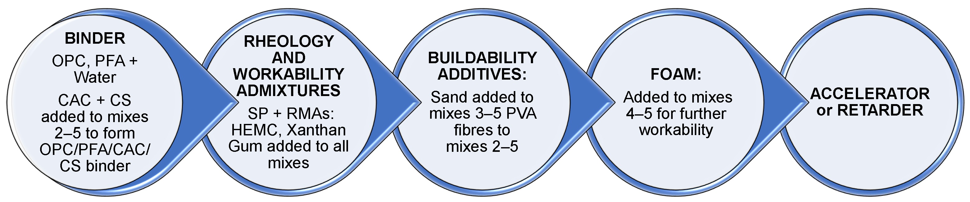
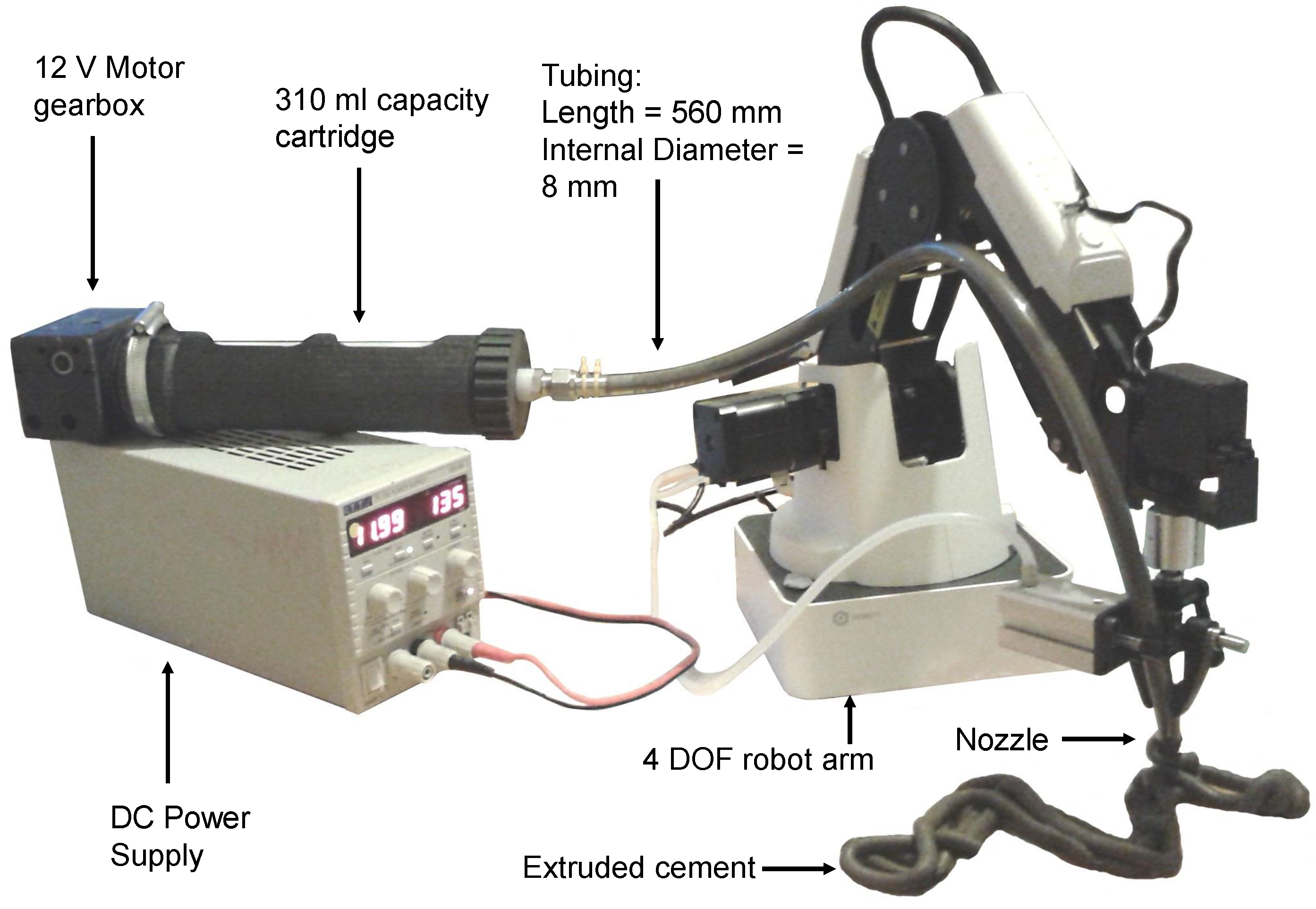
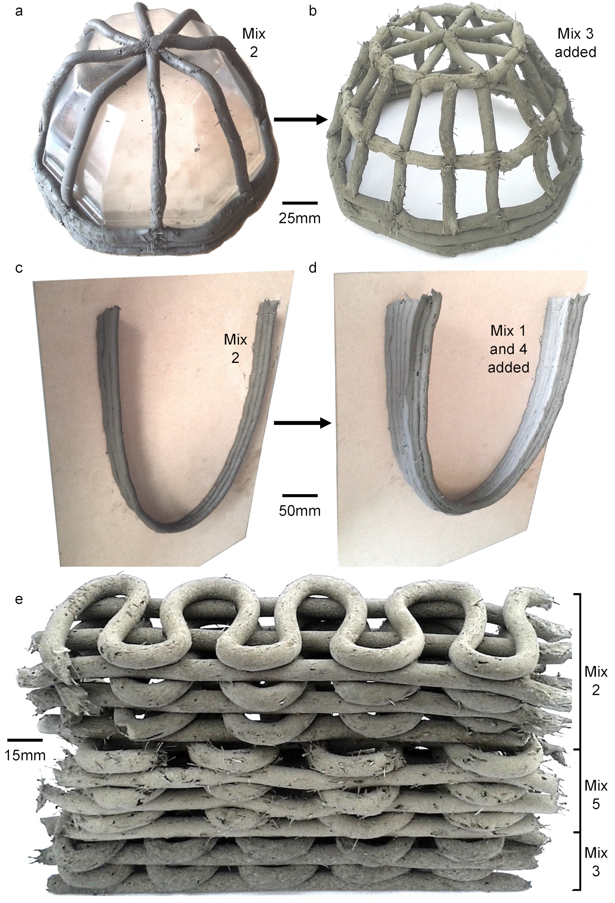
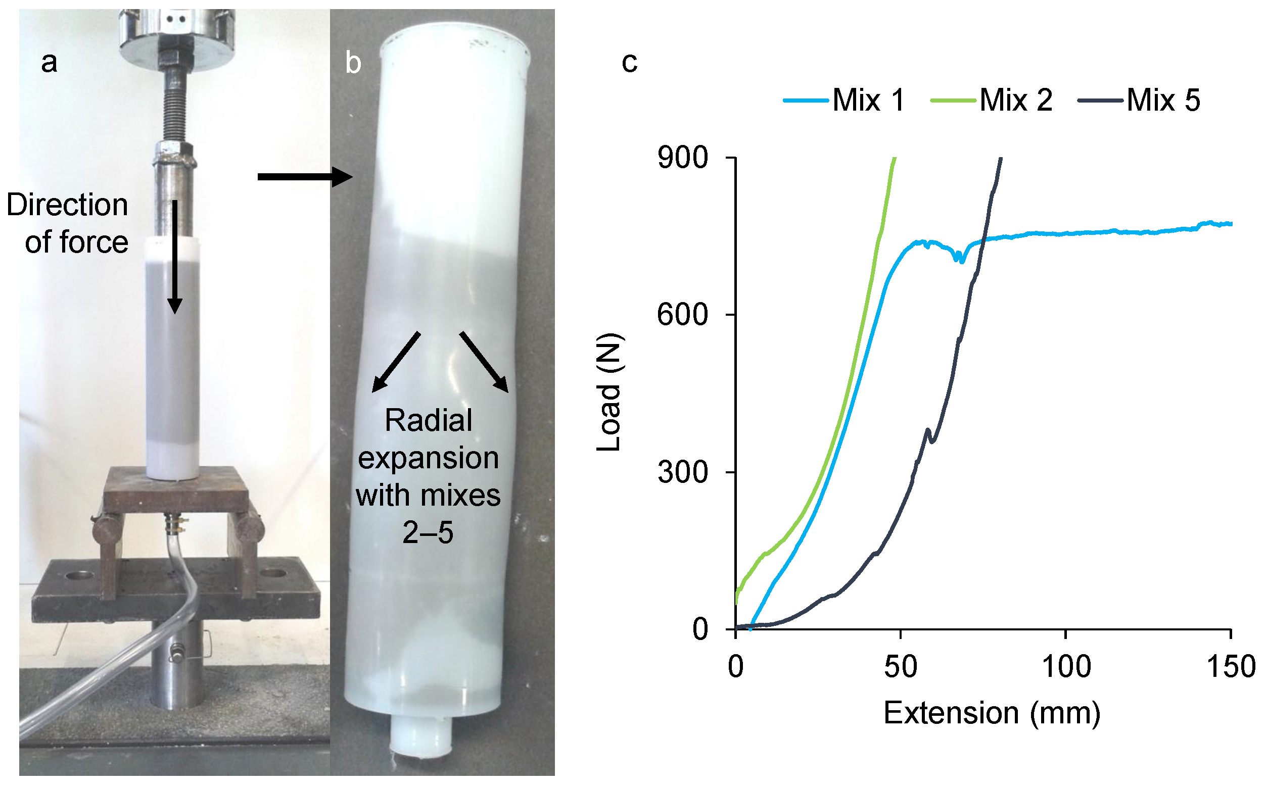
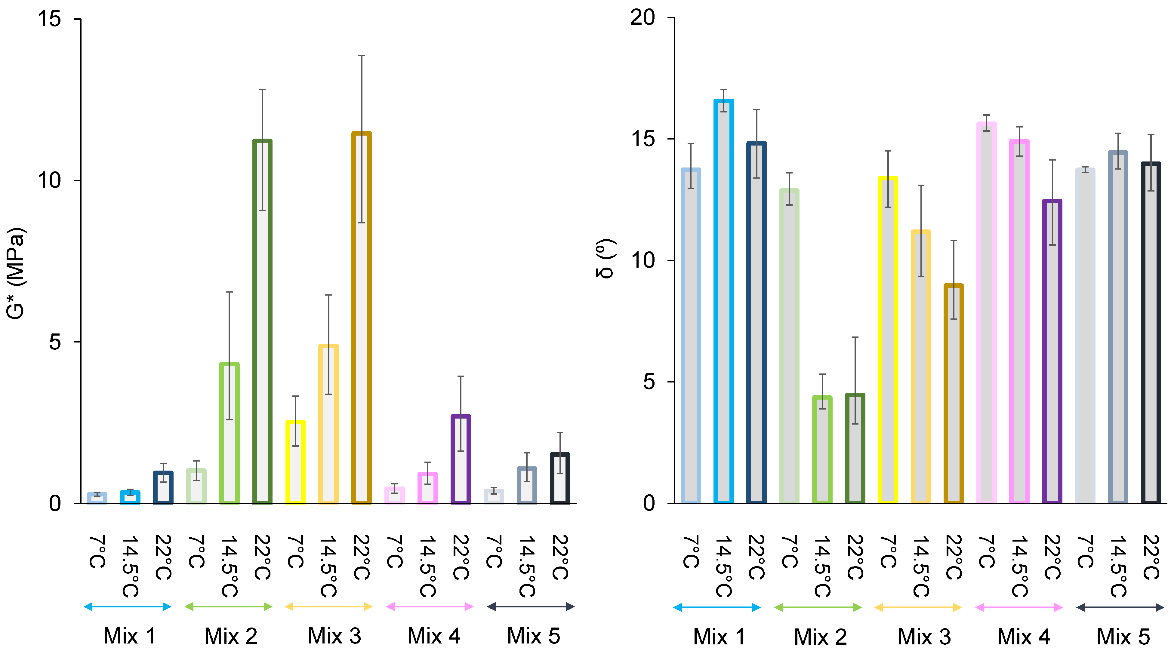
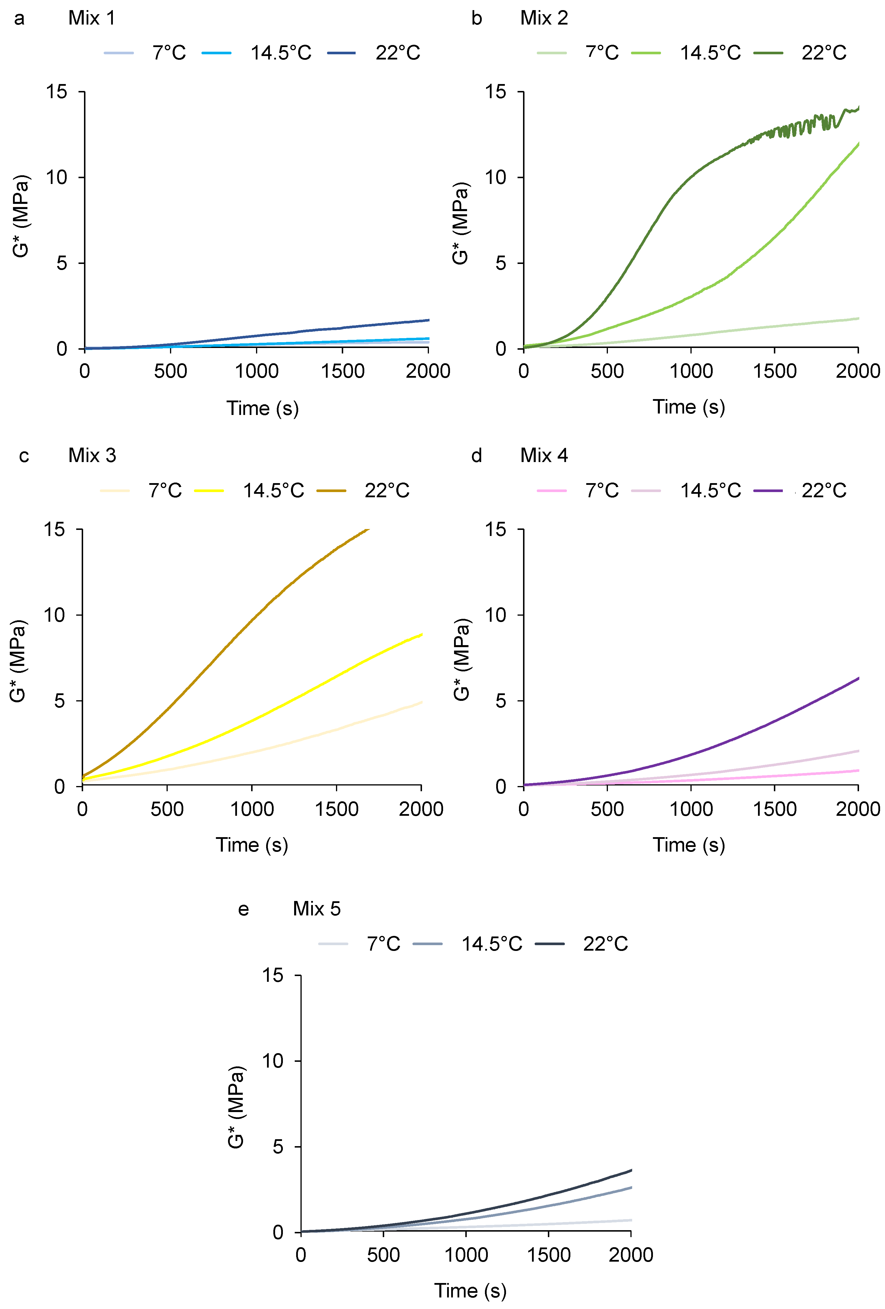
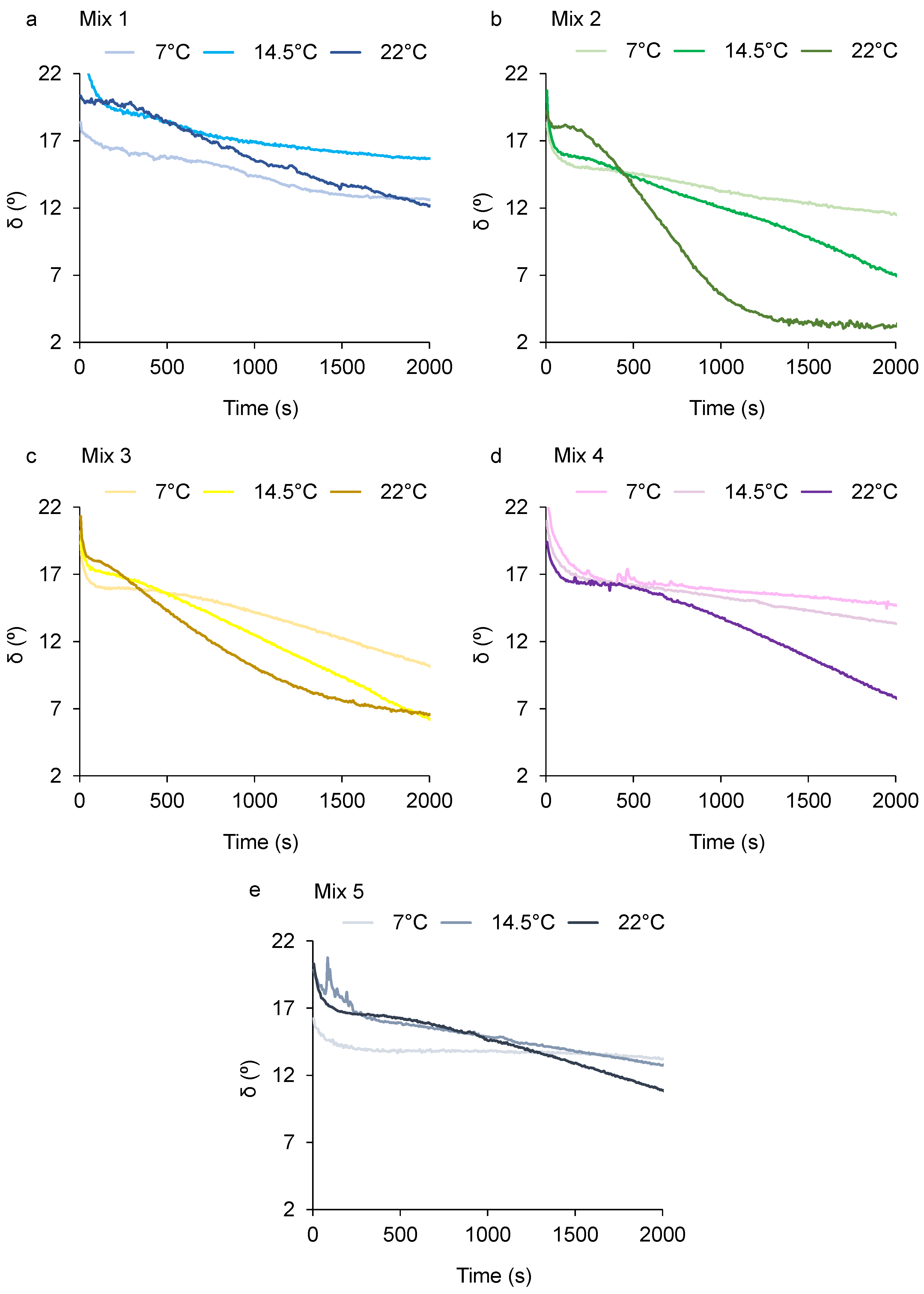
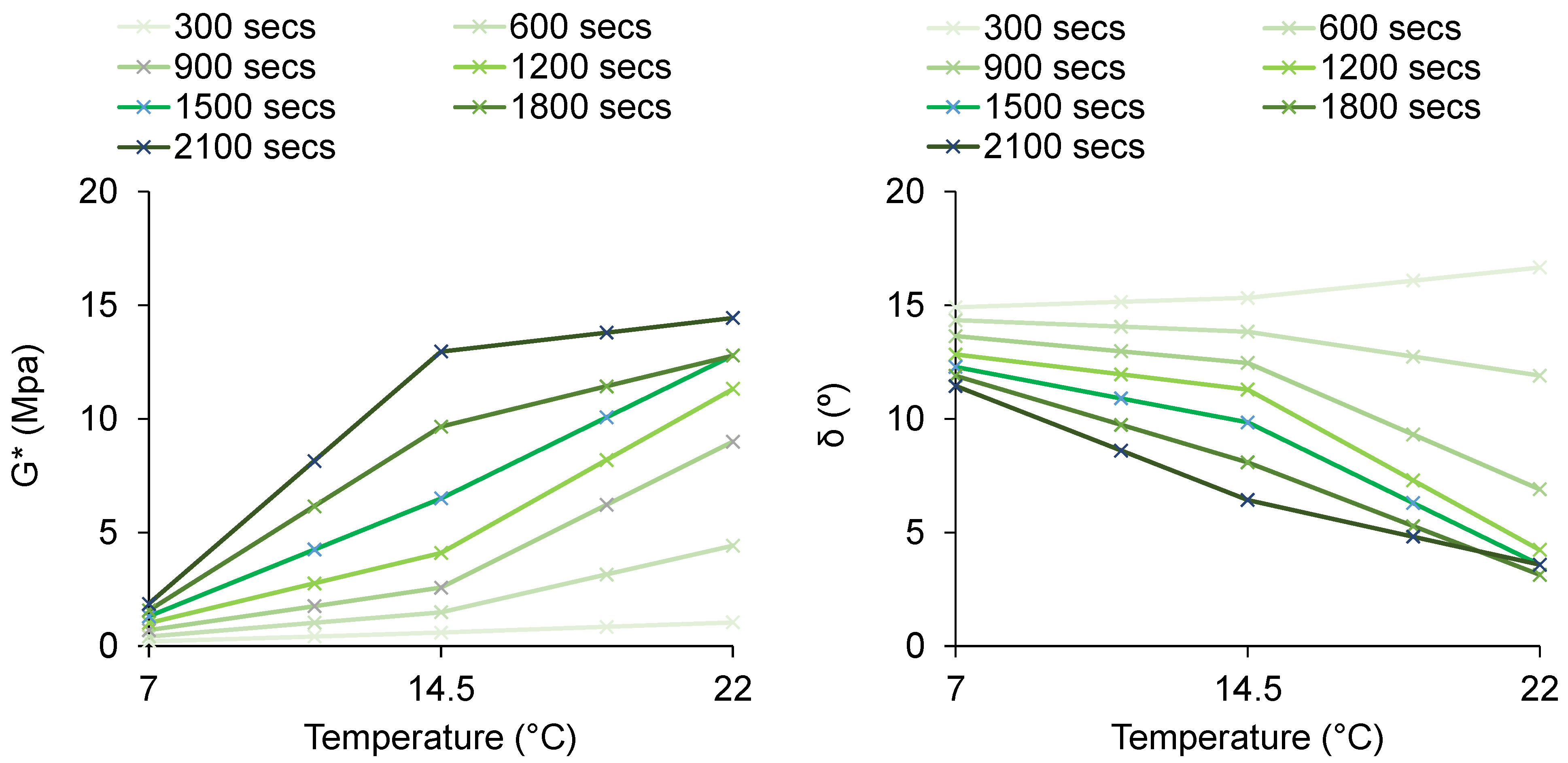
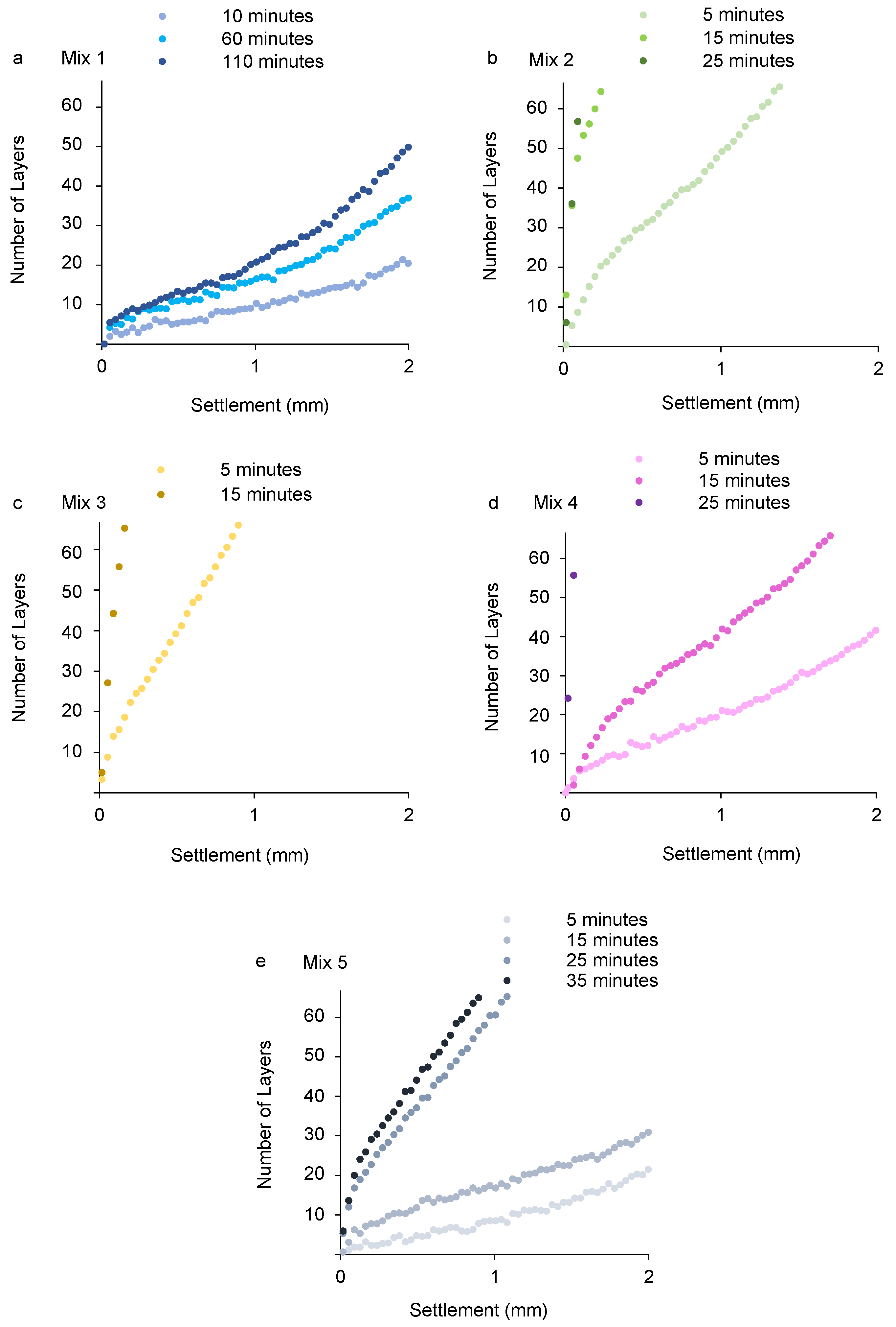
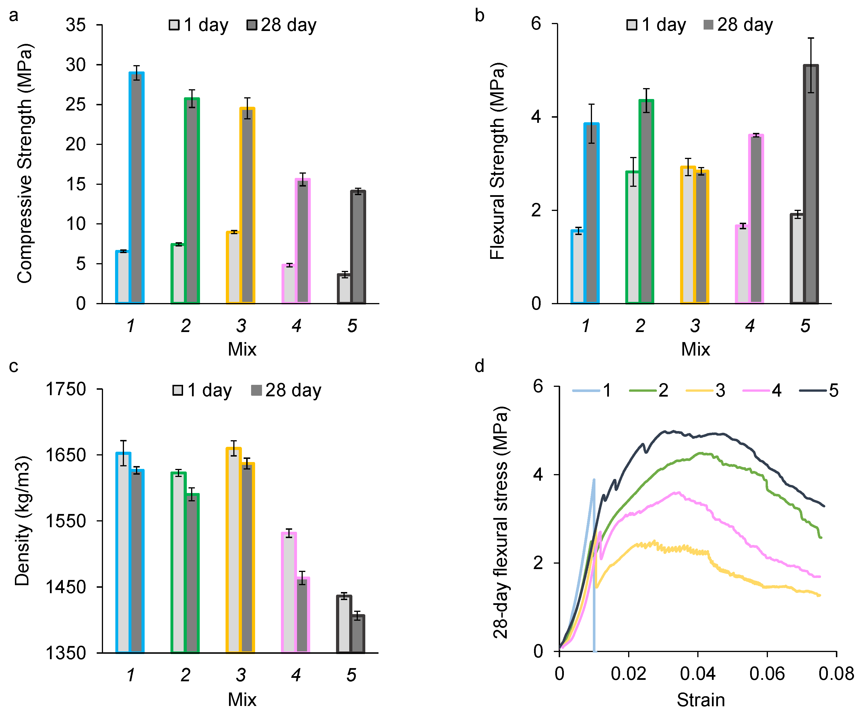
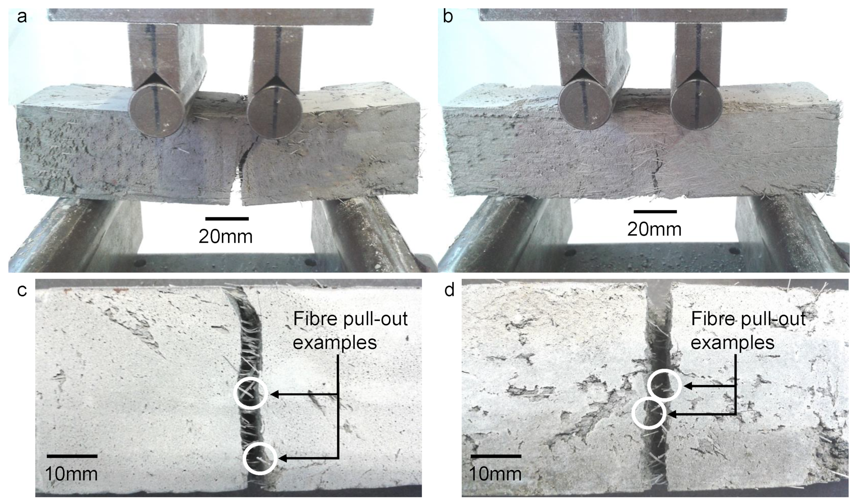
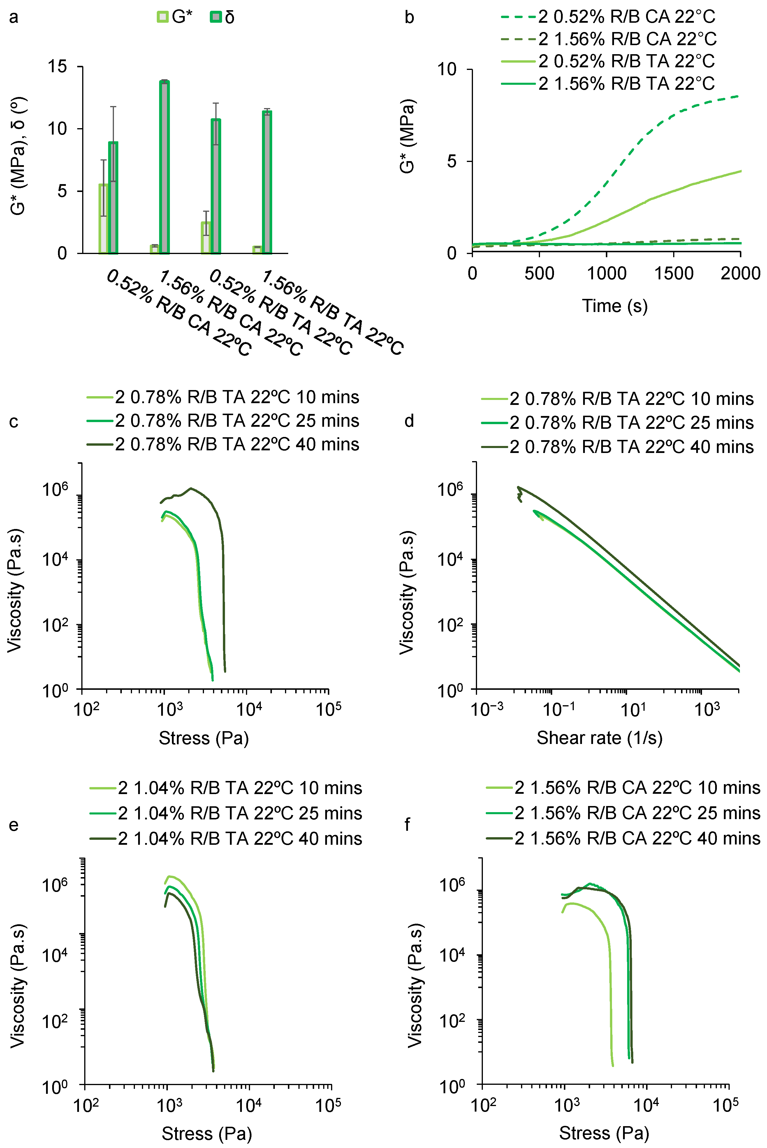
Table 1.
Rietveld quantitative phase analysis of the chemical composition of Dragon Alfa CEM I 42.5 R Portland cement shown as a percentage by weight.
Table 1.
Rietveld quantitative phase analysis of the chemical composition of Dragon Alfa CEM I 42.5 R Portland cement shown as a percentage by weight.
| CEM I Phase | % by wt. |
|---|---|
| Dicalcium silicate CS | 14.6 |
| Tricalcium silicate CS | 71.5 |
| Tricalcium aluminate CA | 7.27 |
| Tetra-calcium aluminoferrite CAF | 4.46 |
| Calcium sulphate phases | 2.16 |
Table 2.
Mixes 1–5 showing constituents in kg/m, and specification along with PVA fibre volumes (FVs) and mix ratios. Please refer to the Abbreviations table for a full listing detailing acronyms and abbreviations used. Mixes as shown were developed in a temperature of 14.5 °C ± 2 °C with a water temperature of 15.5 °C ± 2 °C.
| kg/m3 by wt. | Mix 1 | Mix 2 | Mix 3 | Mix 4 | Mix 5 | Specification |
|---|---|---|---|---|---|---|
| Sand | - | - | 287 | 326 | 298 | <2 mm particles |
| OPC | 770 | 553 | 460 | 391 | 358 | CEM1 42.5R |
| PFA | 415 | 298 | 248 | 211 | 193 | Type ‘F’ EN-450 |
| CAC | - | 229 | 190 | 162 | 134 | Ternal SE |
| CS | - | 76.4 | 63.5 | 54.0 | 63.6 | Anhydrite |
| SP | 11.8 | 15.0 | 12.5 | 10.6 | 9.69 | Peramin SMF10 |
| Water | 545 | 526 | 438 | 397 | 363 | - |
| PVA fibres | - | 13.9 | 9.70 | 13.2 | 24.7 | 350 m diameter |
| Accelerator | - | - | 10.5 | 6.11 | 5.59 | Peramin AXL80 |
| Retarder | - | 1.38 | - | - | - | citric, tartaric |
| HEMC | 5.12 | 5.06 | 5.07 | 4.70 | 4.38 | Walocel MKX6000 |
| XG | 10.9 | 8.99 | 9.01 | 10.1 | 8.76 | - |
| Foam | - | - | - | 49.5 | 76.3 | Foaming agent |
| Total | 1757 | 1726 | 1733 | 1634 | 1538 | - |
| S/B | - | - | 0.30 | 0.40 | 0.40 | - |
| W/B | 0.47 | 0.47 | 0.47 | 0.50 | 0.50 | - |
| FV (%) | - | 1.00 | 0.70 | 1.00 | 2.00 | - |
| A/B (%) | - | - | 1.10 | 0.75 | 0.75 | - |
| R/B (%) | - | 0.12 | - | - | - | - |
Table 3.
Power required for the device plunger to push mixes 1–5 (and an empty cartridge for comparison).
Table 3.
Power required for the device plunger to push mixes 1–5 (and an empty cartridge for comparison).
| Fresh Mix | Tube-Start Power (W) | Tube-Middle Power (W) | Start of Extrusion Power (W) | End of Extrusion Power (W) |
|---|---|---|---|---|
| Empty | 1.68 | 1.68 | 1.68 | 1.68 |
| 1 | 2.40 | 2.76 | 2.88 | 2.88 |
| 2 | 2.76 | 3.60 | 4.20 | 4.80 |
| 3 | 2.76 | 3.48 | 4.68 | 4.68 |
| 4 | 2.28 | 3.00 | 4.20 | 4.20 |
| 5 | 2.16 | 2.76 | 3.48 | 3.84 |
Table 4.
Indication of select material properties for an OPC/PFA/CAC/CS cementitious binder-based pseudoplastic material suitable for AAM extrusion. 28 d = 28 days. G* = Complex Modulus. Phase Angle.
Table 4.
Indication of select material properties for an OPC/PFA/CAC/CS cementitious binder-based pseudoplastic material suitable for AAM extrusion. 28 d = 28 days. G* = Complex Modulus. Phase Angle.
| Compressive Strength (28 d) | Flexural Strength (28 d) | Yield Stress (Fresh Mix) | G* 2000 s at 14.5 °C (Fresh Mix) | 2000 s at 14.5 °C (Fresh Mix) |
|---|---|---|---|---|
| 25 MPa | 4 MPa | 1.1–1.4 KPa | 2–5 MPa | 12–15 |
Disclaimer/Publisher’s Note: The statements, opinions and data contained in all publications are solely those of the individual author(s) and contributor(s) and not of MDPI and/or the editor(s). MDPI and/or the editor(s) disclaim responsibility for any injury to people or property resulting from any ideas, methods, instructions or products referred to in the content. |
© 2023 by the authors. Licensee MDPI, Basel, Switzerland. This article is an open access article distributed under the terms and conditions of the Creative Commons Attribution (CC BY) license (https://creativecommons.org/licenses/by/4.0/).
Share and Cite
MDPI and ACS Style
Dams, B.; Shepherd, P.; Ball, R.J. Development and Performance Evaluation of Fibrous Pseudoplastic Quaternary Cement Systems for Aerial Additive Manufacturing. Designs 2023, 7, 137. https://doi.org/10.3390/designs7060137
AMA Style
Dams B, Shepherd P, Ball RJ. Development and Performance Evaluation of Fibrous Pseudoplastic Quaternary Cement Systems for Aerial Additive Manufacturing. Designs. 2023; 7(6):137. https://doi.org/10.3390/designs7060137
Chicago/Turabian StyleDams, Barrie, Paul Shepherd, and Richard J. Ball. 2023. "Development and Performance Evaluation of Fibrous Pseudoplastic Quaternary Cement Systems for Aerial Additive Manufacturing" Designs 7, no. 6: 137. https://doi.org/10.3390/designs7060137