
A Review of Novel and Non-Conventional Propulsion Integrations for Next-Generation Aircraft


1
Department of Civil and Industrial Engineering, University of Pisa, Via Caruso 8, 56122 Pisa, Italy
2
Embraer S.A., Research & Development, São José dos Campos 12227-901, Brazil
3
Sao Carlos School of Engineering, University of Sao Paulo, Sao Carlos 13563-120, Brazil
*
Author to whom correspondence should be addressed.
Designs 2024, 8(2), 20; https://doi.org/10.3390/designs8020020
Submission received: 18 January 2024
/
Revised: 9 February 2024
/
Accepted: 15 February 2024
/
Published: 20 February 2024
(This article belongs to the Special Issue Advances in Aircraft Propulsion System Modelling, Design and Simulation)
Abstract
:The aim of this review paper is to collect and discuss the most relevant and updated contributions in the literature regarding studies on new or non-conventional technologies for propulsion–airframe integration. Specifically, the focus is given to both evolutionary technologies, such as ultra-high bypass ratio turbofan engines, and breakthrough propulsive concepts, represented in this frame by boundary layer ingestion engines and distributed propulsion architectures. The discussion focuses mainly on the integration effects of these propulsion technologies, with the aim of defining performance interactions with the overall aircraft, in terms of aerodynamic, propulsive, operating and mission performance. Hence, this work aims to analyse these technologies from a general perspective, related to the effects they have on overall aircraft design and performance, primarily considering the fuel consumption as a main metric. Potential advantages but also possible drawbacks or detected showstoppers are proposed and discussed with the aim of providing as broad a framework as possible for the aircraft design development roadmap for these emerging propulsive technologies.
1. Introduction
Recent developments in the design of transport aircraft are increasingly focusing on the search for innovative solutions to reduce the environmental impact of flight operations [1,2,3,4,5,6,7,8,9,10]. In this context, specific attention is being devoted to research into non-conventional solutions for the integration of the propulsion system, involving two different interconnected technological threads. From a general point of view, new types of propulsion systems are under investigation, and technologies involving new fuels, such as hydrogen [11,12,13,14,15,16,17,18] or sustainable aviation fuels [19,20,21,22], or electric and hybrid-electric powertrains [23,24,25,26,27,28,29,30,31,32], are under development to provide breakthrough forward advancements in the field. In addition to these important innovations, and in a way that is generally complementary, non-conventional powertrain/airframe integrations are increasingly being investigated since, either as standalone or in combination with previous new power supply concepts, they can contribute to general improvements in aircraft performance, with significant implications for reducing environmental impact. Among the advanced technologies under investigation, it is worth mentioning distributed propulsion, which is gaining much interest, especially in the context of synergistic integration with electric powertrains. Recent studies are also being conducted on the potential aerodynamic benefit to be obtained from wingtip-mounted propulsive elements. New ways of propulsion–airframe integration also concern designs involving the so-called boundary layer ingestion, which has the potential to improve the aircraft’s aerodynamic and propulsive performance. This technology allows numerous possibilities for different propulsion system integrations, such as the propulsive fuselage concept. In general, several other non-conventional integrations of the engine to the airframe are under investigation; furthermore, more and more interconnections between the design of unconventional aircraft architectures, such as the blended wing body [33,34,35,36,37] or the box-wing [38,39,40,41,42], and the integration of innovative propulsion concepts are being explored. The combination of different disruptive elements, indeed, could lead to the conceptualisation of future aircraft entirely different from those widely utilized nowadays and with significantly improved environmental performance. On the other hand, the evolutionary development of current technology is also a possible way to introduce overall aircraft performance benefit. In this regard, the development of more efficient turbofan and turboprop engines is considered as a reliable path to introduce propulsive benefits in the very near future. Specifically, by improving their propulsive efficiency, overall aircraft performance benefit could be achieved. This can mainly be achieved by means of increasing the engine bypass ratio well beyond the state-of-the-art values, leading to the so-called ultra-high bypass ratio turbofans and to open rotor engines. Propulsive efficiency augmentation in ultra-high-bypass ratio engines is primarily related to the substantial acceleration of a larger air mass at a lower velocity. In contrast to low-bypass turbofans, this design exploits the contribution of a significant bypass air fraction that does not undergo combustion, increasing overall propulsion efficiency.
In this framework, the aim of this article is to present an extensive analysis of the current literature on innovative or non-conventional integrations of engines and airframes for future aircraft designed to have a low environmental impact. Specifically, the discussion focuses on the technological aspects of engine integration in the whole aircraft, i.e., the areas that interdisciplinarily involve aerodynamic and propulsive effects that impact overall aircraft performance. In this regard, therefore, attention is given to propulsion typologies and their integration, installation and interference effects, while the reader is invited to refer to other studies for more in-depth analyses of innovative energy and power sources, such as hydrogen, sustainable aviation fuels or electric powertrains.
This paper is organized as follows: Section 2 is focused on the evolutionary development of turbofan engines, namely on the design, integration, installation and performance analysis of ultra-high bypass ratio turbofans; Section 3 provides a wide overview of the distributed propulsion applications, mainly focusing on the beneficial synergy that this propulsive concept may have with hybrid-electric powertrains; Section 4 discusses the boundary layer ingestion engines integration, on both traditional and non-conventional airframes; Section 5 briefly describes other disruptive propulsion–airframe integration advanced concepts; and finally, Section 6 gives the conclusion of the work.
2. Advanced Turbofan
2.1. Overview of Ultra-High Bypass Ratio Turbofan
Scientific research focusing on the incremental technological development of advanced aeronautical engines, capable of reducing fuel consumption, pollutant emissions and noise, is a topic of extreme interest. In this context, the report presented in [43] provides an overview of the European scenario, describing the largest research and development projects on next-generation turbofans and the related enabling technologies. Other overviews on the evolutionary technological development of aircraft turbofans are also given in [44,45]. One of the most promising technologies for increasing the propulsive efficiency of future aero engines is the ultra-high bypass ratio (UHBR) turbofan. This specific technology, which has been widely studied for a long time, represents a step of major innovation in the incremental and evolutionary technological development of turbofans. Specifically, UHBR turbofans are based on conventional turbofans in which the bypass ratio (BPR) is increased considerably beyond the state-of-the-art values, with the aim of maximizing the engine’s propulsive efficiency [46,47]. Specifically, the overall efficiency of a turbofan can be expressed as follows:
where the term is the thermal efficiency, defined as the ratio between the rate of increase in kinetic energy of the propellant and the fuel power, and the term is the propulsive efficiency, which is defined as the ratio between the thrust power (i.e., the thrust T multiplied by the flight speed u) and the increase in kinetic energy provided to the engine mass flow, viz.
where is the air mass flow and is the exhaust speed. As the turbofan thrust can be consistently expressed as
Equation (2) can also be rewritten in a compact form as follows:
where the quantity T/ is defined as the specific thrust. Note that increases in are obtained as T/ decreases, i.e., keeping the thrust value constant, the engine mass flow rate should be increased, resulting in a reduction in exhaust speed. This particular effect can be obtained by increasing the engine bypass ratio and reducing the fan pressure ratio (FPR), in a theoretically incremental way, thereby providing a practical interest in the development of UHBR turbofans.
The interest in the study and advanced development of such a concept lies both in its potential benefit in terms of propulsive efficiency (and also noise reductions as discussed in [48,49,50]) but also because UHBR turbofans represent a potentially (very) significant technological brick with a smooth and quasi-evolutionary implementation, i.e., not based on futuristic and disruptive ideas that rather require conceptual validation before prototypical applications. Its reliance on a base concept that has been extensively validated in service makes it of great interest to the aeronautical scientific community, and its integration with next-generation aircraft appears to be decidedly promising. But not all that glitters is gold.
In fact, to date, there are still numerous problems related to the actual integration of UHBR turbofans on transport aircraft. In particular, reducing the specific thrust, or increasing the mass flow, entails an increase (even substantial) in the fan size. This implies a potential increase in the weights of the entire propulsive unit, together with an increase in the size of the nacelle and therefore in friction drag, as well as the possible “amplification” of aerodynamic interference effects between the turbofan and the airframe [51]. These secondary effects, therefore, could theoretically (partially or totally) undermine the benefit obtainable in terms of specific fuel consumption by increasing the BPR, affecting the overall performance of the whole aircraft (i.e., block fuel consumption). For this reason, in order to effectively foster the development and actual implementation of the UHBR turbofan, in addition to evaluating technological implementations in advanced materials and more efficient components [52], in nacelle design [53,54] and its shape optimization [55,56], it is also crucial to take into account the effects of the turbofan installation [57], together with the mission performance of the complete aircraft [58].
To specifically highlight these aspects, the following review of scientific studies available in the literature on UHBR turbofans is proposed as follows. First, the studies regarding the UHBR turbofan technology itself (isolated) are discussed and commented on, i.e., the theoretical benefits that it may entail in terms of propulsive efficiency and specific fuel consumption. Subsequently, the studies relating to the characterisation of installation effects and their impact in terms of aircraft overall performance are discussed. Finally, potential installations of UHBR turbofans on aircraft with innovative airframes are presented, which are intended to (partially or totally) overcome the limitations introduced by the underwing installation of the UHBR turbofan on the traditional tube-and-wing aircraft configuration.
2.2. Uninstalled UHBR Turbofan Features
Studies carried out in the 1990s paved the way for the characterisation of performance, potential and general issues related to turbofan design with increasing BPRs up to values identifiable as UHBR. Indeed, the interest in this type of turbofan is not new, and it places its initial investigations back in time, as proposed in [59]. In this early study [59], the problem of the development and integration of the UHBR turbofan is discussed in a general way, and the potential of such a development is addressed qualitatively in the context of the technological scenario of the time. Specifically, the design requirements and figures of merit differed from those of today, while the interesting work [59] represents an initial general overview on the potential of the UHBR turbofan technology.
Another of the early reference studies is presented in [60], which proposes an analysis of turbofan engine performance as the BPR varies, starting from 5 up to 17.5. This work mainly focuses on the theoretically obtainable performance of the isolated propulsion unit, especially in terms of thrust specific fuel consumption (TSFC), but also presents a preliminary analysis of installation effects, in terms of penalties related to the increased size of the nacelle. As the BPR increases, technological developments are introduced to improve the performance of the turbofan, such as the geared solution for the fan [61,62], the variable pitch mechanism for its blades (variable pitch fan, VPF, [63]) and the variable area nozzle (VAN, [64]). In particular, the VPF, as well as providing optimal operating matching of the fan under all working conditions, enables the fan to be allocated the function of a thrust reverser, eliminating the need to integrate it into the nacelle and thus permitting a much more compact design of the latter. In addition, a preliminary study on the design of the nacelle is discussed to limit the detrimental effects of installing much larger cowls than the state-of-the-art references. The authors of [60] point out that the development of the nacelle for these applications must explore new, more aggressive forms of design, in terms of shape and size, as qualitatively proposed in Figure 1 (which is adapted from [60]), where the cowl is designed to maximise the aerodynamic requirements, i.e., to minimize the cruise drag. The study [60] therefore concludes by offering a scenario, albeit preliminary and limited to its timeframe state-of-the-art comparisons, in which UHBR turbofans can be effective solutions for reducing fuel consumption, if they are properly optimized in their operating cycle and aerodynamic shapes and if they are coupled with an appropriate technological development of their components.
In the same path of the precursor work presented in [60], a more recent ref. [65] has also proposed an investigation on the effects of introducing variable pitch fans on UHBR turbofans, highlighting the potential benefits that such technology could have in reducing the nacelle size and thus its contribution to drag and weight. In particular, VPF is proposed by [65] as an effective solution to ensure the best performance of the turbofan in terms of specific fuel consumption, to control its stability margins under different operating conditions, and most importantly to ensure the design of a compact and slim nacelle. Hence, the work proposed in [65] focuses exclusively on a simplified model that can provide a general understanding of the benefits obtainable from the VPF integrated on a UHBR turbofan. The studied reference turbofan exhibits a BPR equal to 17.5, while, by exploiting a VPF and coupling it with a new thrust management method, the study in [65] predicts a further 2% reduction in TSFC compared to the reference turbofan without a VPF.
An additional work that analyses the potential effects of VPF in a general way is [66], together with the potential impacts achievable through the integration of a VAN. This reference contains a qualitative study of the comparison between a VPF and a VAN applied to a geared turbofan UHBR and focuses on the ranges of the BPR and FPR that could be favourable for the integration of these technologies.
A very interesting study on the analysis of UHBR turbofans is provided by [67]. Specifically, this work aims to study and compare two different UHBR turbofans that could represent the evolutionary technological brick for medium-range, wide-body aircraft applications (4800 nm and 340 pax) for a time horizon beyond 2035. The two types of UHBR turbofans analysed are a direct drive turbofan (DDTF) and a geared turbofan (GTF), with the latter proposed (and demonstrated) as a key enabler technology for the effective development of UHBR turbofans. That work focuses primarily on studying and comparing the performance of the two uninstalled turbofans, but it also provides a conceptual analysis of the effect of engine installation on overall aircraft performance. In particular, the comparative study between the DDTF and GTF is carried out in a parametric way, using the BPR as the main design parameter, with the aim of characterising performance trends at a conceptual level, together with the identification of optimum ranges and feasibility limits. In order to compare the main architectural differences on turbofan propulsive efficiency, the same technological hypotheses were made with regard to engine components and thermal cycle efficiency (in particular, the same overall pressure ratio, OPR, and turbine entry temperature, TET, were assumed). The analysed DDTF configuration has a three-spool architecture, while the matching between the rotational speeds of the fan and the low-pressure turbine (LPT) represents the main issue in the design of this propulsion system. Specifically, increasing the BPR (and, consequently, the fan diameter) implies the reduction of its rotational speed to limit the tip velocities of the fan blades. This result also limits the rotational speed of the LPT, and this requirement leads to an increase in the number of stages (i.e., the sequence of rotating blades and stationary vanes) of the LPT, causing limitations on the design space (e.g., constraints on the maximum number of stages) and increases in weight and complexity. In contrast, this problem does not exist for the GTF, since the increase in fan size and related constraints on blade tip speed only affect the design of a proper gear system and its reduction ratio. The performance of the two architectures in terms of SFC of the uninstalled engine at varying BPR is shown in Figure 2, which has been adapted from [67]. It is observed that the DDTF architecture shows a minimum in the SFC curve, which shifts towards a higher BPR as the number of stages of the LPT increases. However, preliminarily setting the maximum number of stages at nine for reasons of practical feasibility, it is observed that the optimum is achieved for a BPR equal to 14, with a benefit of about 20% with respect to the turbofan technology of year 2000. The situation seems to be better in the case of the GTF, which has no minimums when varying the BPR in the investigated range. The limit, therefore, can be selected indicatively in relation to other constraints, such as the available underwing clearance or manufacturing complexity. In particular, its benefits in predicted SFC can reach about the 25% with respect to the technological state of year 2000.
The results in Figure 2, however, do not reflect the general effects on aircraft performance, i.e., block fuel consumption, which also takes into account the increase in weight and drag introduced by high BPR turbofans. The authors of [67], therefore, provide a preliminary study considering these effects as well, i.e., integrating with very simplified models the increases in drag and weight [68], and then indicatively calculating the aircraft’s block fuel. The results between an uninstalled engine and a complete aircraft are different, as can be seen in Figure 3, which has been adapted from [67]. In particular, for the DDTF, engine–airframe integration effects cause the optimum BPR to deviate from 14 to 13, while still providing a fairly limited performance increase. For the GTF, the benefits of increasing the BPR outweigh its penalties over the entire interval considered, but the beneficial effects beyond the optimal uninstalled BPR are quite negligible and therefore do not suggest increasing the size, and thus the manufacturing complexity, of the powerplant. In general, these results are qualitative and indicative, and more accurate assessments are needed to properly evaluate the turbofan integration and installation effects, as discussed in Section 2.3.
The study proposed in [67], therefore, although based on very preliminary models, indicates that the technological way forward for the development and integration of UHBR turbofans lies in the GTF solution; an initial analysis of the airframe integration effects is presented, but the limitations of the models do not allow general indications to be extracted and suggest the use of incremental fidelity models for the study of the performance of the complete aircraft. A similar study is also proposed in [69], where the performance of DDTF and GTF are compared by also assessing the effects in terms of emitted noise. The best trade-off solutions are evaluated using Pareto front analysis, whereby the best UHBPR architectures are identified in terms of their effects on overall aircraft performance, considering both block fuel and noise. Different airframe configurations are also considered. In general, the conclusions of that study [69] are similar to what was reported in [67], with the GTF providing the best performance enhancement opportunities for UHBR turbofans in terms of fuel consumption and, in this case, also noise.
2.3. Assesment of UHBR Installation Effects
As previously stated, the beneficial effects in terms of specific fuel consumption due to the increase in BPR may be opposite to the associated detrimental effects, such as increased drag, aerodynamic interference, or weights. Such a scenario, which contrasts the performance study of the uninstalled versus the installed engine, is completer and more comprehensive of aircraft-level effects and can be qualitatively summarized by the diagram in Figure 4, which has been adapted from [70]. Indeed, aircraft fuel consumption is primarily related to engine performance (i.e., specific fuel consumption) and aerodynamic drag; increasing the BPR improves propulsive performance but also gradually results in increased powerplant contribution to the drag. There is therefore a trade-off point, beyond which the contribution of increased drag may outweigh the benefit in terms of propulsive efficiency, thus leading to an increase in fuel consumption with respect to the optimum. This trend, as we discuss in the several examples later in this section, depends on the design of the aircraft and of the powerplant and on their integration. In the following, a review of the studies detailing the installation effects is proposed and discussed, with a main focus on the relative positioning between turbofan and airframe [71], the related aerodynamic analysis and the overall mission performance of the aircraft.
The work presented in [70] has preliminarily paved the way for the analysis of turbofan installation effects on aircraft aerodynamics, providing an introductory focus on the implications related to increasing the BPR. In particular, this work [70] is characterised by a preliminary numerical study, based on the use of the Euler model coupled with viscous correction, and is focused on the evaluation of lift loss due to the size and positioning of high bypass ratio engines, such as UHBR turbofans (with a BPR roughly equal to 15). The relevance of such analyses is significant, as in a complex multidisciplinary context such as the mutual interference effects between engine and wing, identifying strategies that could minimize potential detrimental effects is crucial. The results discussed in [70] for the standard underwing assembly case, although qualitative, highlight the influence of increasing engine size and its positioning on wing lift loss. Specifically, it is observed that there may be a proportionality between lift loss and turbofan size. Furthermore, it is found that a vertical shift of the engine may not have a greater influence on aerodynamic interference, while an upstream shift of the engine with respect to the wing may reduce lift loss.
The more recent work proposed in [72] also presents a preliminary numerical analysis of the effects of UHBR engine positioning on aerodynamic interference with the wing. In particular, a numerical optimization technique is used to identify the optimal positioning of a UHBR turbofan with a BPR equal to 15 which is installed in a conventional underwing configuration on a single-aisle aircraft. The solver used is based on RANS models, the objective function is the minimization of aerodynamic drag for the same lift, and the main design variables (DVs) are the horizontal and vertical positioning of the turbofan with respect to the wing. Specifically, the search for the optimum is carried out using surrogate models, which are able not only to identify an optimum of the problem, but also to map the design space in a computationally efficient manner, with the aim of identifying the influence of variations in the DVs on the objective function. The main outcomes presented in [72] indicate that the horizontal positioning of the turbofan has two contrasting effects on nacelle and wing drag: in fact, close coupling reduces wing drag, while more spaced positioning reduces nacelle drag. The effect of vertical location, on the other hand, is severely limited by the spatial constraints imposed by ground clearance and presence of the wing, limits that are preponderant in the case of UHBR turbofans. However, it is generally observed that it may be aerodynamically beneficial to separate the engine vertically from the wing. In addition, a general focus is also proposed on the turbofan’s angular configuration (pitch and toe-in), which impacts performance and must therefore be taken into account during the design process.
A more advanced analysis is proposed in [73], in which CFD simulations with steady RANS solvers are used to thoroughly investigate the effects of UHBR turbofan installation. Starting from the results previously obtained by the same authors in [74], numerical simulations are used to assess and characterise the complex aerodynamic flow around the nacelle of a UHBR turbofan (with a value of BPR > 14) mounted underwing to the long-range NASA common research model [75] and to evaluate the impact of engine positioning on the mutual interaction with the wing in cruise condition (where the Mach number is 0.85 and the aircraft altitude is 10,667 m). The work accurately demonstrates that the proper engine positioning with respect to the wing is of primary relevance to interference effects and aerodynamic performance. Ahead of the installation choices, the need to adopt very compact installation arrangements when dealing with UHBR engines is a prerequisite, due to tight dimensional constraints (e.g., distance to the ground and/or length of the main landing gear). Optimizing such positioning, therefore, being the main degree of freedom available to act on aerodynamic interference effects, is crucial to compensate for the increases in drag due to the larger dimensions of the UHBR propulsion system. Eighteen different positions of the UHBR turbofan were analysed in [73], with longitudinal and height variations, as schematised in Figure 5, which has been adapted from [73].
All simulations are carried out with constant lift and imposing equal drag and thrust (this second point is satisfied by iterating the engine throttle). Although the flow in the installation area is very complex and the mutual interference makes it impossible to isolate the individual effects of each component, the breakdown of the drag between wing and nacelle nevertheless provides an effective picture of the effects of engine positioning. Even the analysis of the results proposed in [73] shows that the longitudinal position of the turbofan has a larger influence than the vertical position on both the wing and nacelle drag and that the effects are conflicting. For the wing, the drag decreases as the engine approaches longitudinally, while that of the nacelle decreases when it is in a more distant position upstream of the wing. It is therefore necessary to use, on a case-by-case basis, optimization techniques capable of minimizing the overall wing–engine drag, i.e., to identify the best trade-off in the positioning of the UHBR turbofan for the specific aircraft considered. The values of percentage drag variations for nacelle, wing and their integration with respect to engine positioning, assessed in [73], is reported in Figure 6, showing the contrasting trends between wing and nacelle and the need to find trade-off solutions.
An applied extension of this study, and of its related computational framework, is described in [76], where detailed aerodynamic simulation of the combined UHBR turbofan and airframe is used to provide information to accurately calculate aircraft mission fuel consumption. Specifically, both the thermodynamic analysis of the turbofan and the advanced simulation of the aircraft’s transonic aerodynamics by means of CFD, including the modelling of installation effects, are used to obtain information on the state of the aircraft at different points of the cruise and thus estimate fuel consumption in a significantly more realistic way than the use of semi-empirical models. In particular, the characterisation of the aerodynamic flow using CFD is assessed by imposing the equilibrium of the aircraft at specific operating points of the cruise in which the conditions of weight, lift, drag and thrust are differing. The precise evaluation of consumption during the cruise and of the variation of aerodynamic drag in the different operating conditions, also allows the definition of the UHBR turbofan thrust profile and aircraft lift that guarantee equilibrium. This interrelation between the aerodynamic and propulsive forces has a rigorous basis as the modelling of the UHBR turbofan/wing interference effects, which can contribute around 15% of the total airframe drag, are modelled in detail, as already described in [73]. Obviously, these advanced evaluations, although guaranteeing an accurate quantitative estimate, imply onerous computational costs. Accordingly, such techniques currently remain only realistically valid for verifications at an advanced design stage.
In the same light is the research proposed in [77], in which a study on installation effects and their impact on aircraft performance is presented. Two different turbofans are compared, one with a BPR equal to 10.4 (baseline) and one with a BPR equal to 17.8 (UHBR), installed on a 300-seat aircraft with a reference cruise performed at 10,000 m and Mach number equal to 0.82. In this context, the engine’s isolated performance is evaluated first, therefore focusing mainly on the propulsive efficiency. Subsequently, by means of CFD analysis with a compressible RANS solver, the aerodynamic interference effects are assessed, depending on the relative position of the turbofans with respect to the wing, in the traditional underwing assembly. Figure 7 shows the Mach contour maps of the two optimal turbofan positionings for the engines considered in the study [77].
The aerodynamic and propulsive performances, together with the estimation of the powerplant weights by means of statistical models, are then integrated within an aircraft cruise simulation that allows a preliminary estimation of the aircraft’s performance in terms of fuel consumption. The results show that the UHBR turbofan, compared to the baseline, offers a reduction in specific consumption of 5.8%, which, when installation and weight increase effects are taken into account, results in a 4.8% reduction in the aircraft’s fuel consumption, considering the cruise phase.
Another interesting aerodynamic aspect is discussed in [78], in which a numerical study on the influence of the position of a UHBR turbofan on the performance of the wing with a high-lift system deployed is presented. In fact, the impact of engine installation could have relevance on the stall behaviour of wings with high-lift systems deployed, as well as on the design of the slat, which could be physically constrained by the presence of the nacelle; see Figure 8 which has been adapted from [78]. The numerical analyses proposed in [78] are based on CFD RANS solvers considering the aborted landing condition, in which the high-lift systems are at their largest extension and the engine thrust is at its maximum. The study aims to offer a preliminary sensitivity analysis to the relative wing positioning of a UHBR turbofan with a BPR equal to 19. The results, although very preliminary, suggest that aerodynamic performance in terms of lift-to-drag ratio is more sensitive than the maximum lift coefficient to turbofan positioning. The study, however, is limited to not very generalized case studies and therefore opens the way for further investigation on this topic.
Moving on from the strictly aerodynamic field and broadening the analysis of works that have dealt with the subject in a more general way, in [79] it is possible to find an initial overall overview of the challenges of UHBR turbofan installation. The work [79], although not recent, offers a broad and general perspective on a multiplicity of aspects characterising the sizing and installation of UHBR engines, including the effects of increased BPR on propulsive efficiency, but also on aircraft performance, the impact in terms of fuel consumption, pollutant and noise emissions, and cost. An interesting point concerns the discussion of the influence that dimensional constraints imposed by ground clearance and regulations may have on the maximum possible size of the UHBR turbofan. Specifically, two dimensional constraints are considered, one related to the space available between the wing and the ground and one related to the nacelle’s ground impact in the event of nose gear collapse. While the first constraint simply represents a spatial limitation, the second must ensure that in the event of a nose gear collapse the nacelle does not suffer any major damage, as a matter of safety and cost. These two constraints are decisive on the maximum dimensions of a UHBR turbofan mounted in the classic underwing configuration. In ref. [79], in the case of an advanced UHBR turbofan with a BPR of 21, it is shown that the aircraft must be equipped with landing gear that are larger than those of the baseline aircraft, as qualitatively proposed in Figure 9, which has been adapted from [79]. Note, however, that such an increase in landing gear length cannot be unbounded. In fact, on the one hand it is associated with considerable increases in weight and design complexity, and on the other hand it must be ensured that the aircraft complies with all airport equipment that are standardised worldwide (e. g. maximum height of passenger doors compatible with boarding equipment/systems). It is therefore evident that in addition to performance trade-offs, space constraints may represent a blocking limitation for the maximum exploitation of UHBR technology.
Similar considerations on installation constraints are discussed qualitatively in [80], where additional limitations are discussed, as the maximum roll angle available before the nacelle ground striking.
2.4. Unconventional UHBR Turbofan–Airframe Installations
As it has been observed in the previous overview of UHBR turbofans mounted in the classic underwing layout, there are several challenges to the actual installation of such engines, especially for very high BPR values; constraints related to ground clearance and nose gear collapse, but also other issues specific to the different disciplines involved, such as structures, aerodynamics and aeroacoustics, could impose additional constraints on the effective integration of underwing UHBR turbofans [72]. For this reason, studies of aircraft in which UHBR engines are installed differently from the canonical underwing assembly, such as in the case of overwing or fuselage installations, or on aircraft configurations with entirely disruptive and unconventional airframes, are of increasing interest.
In this regard, the work presented in [81] proposes a preliminary aerodynamic analysis of the installation effects of a UHBR turbofan mounted in an overwing position and structurally connected to the aircraft by means of a pylon joined to the top of the fuselage. This solution is proposed as beneficial for removing the constraints on the diameter of the turbofan due to the ground clearance in the conventional underwing assembly, while that hypothesis could be questionable, as even the wing could represent a physical constraint for the increase of engine size. However, this assembly is also qualitatively proposed as advantages could be obtained both in terms of noise shielding and in terms of removing constraints and limitations on the design and installation of high-lift systems. The selected reference aircraft features the typical specifications of the so-called middle of the market [82], with a number of passengers equal to 250, a design range of 4600 nm and a selected turbofan with a BPR equal to 16.3. A CFD RANS analysis campaign is discussed in [81], considering an operating point in cruise (with a Mach number equal to 0.83 and an altitude of 37,000 ft) and with the aim of qualitatively highlighting the effects of the overwing assembly of the UHBR turbofan. In this context, the modification that the presence of the engine introduces in the pressure field of the upper wing is highlighted; see Figure 10, which has been adapted from [81].
This interference effect significantly reduces the lifting capability of the wing, and it therefore introduces the need to redesign the lifting surface, both in terms of twist distribution and shape. A clear correlation is also identified between the position of the engine and the overall increase in drag, varying from 16% to 50% with respect to the clean condition. Also, in this case, as in the underwing layout, an opposite trend with respect to the isolated assessment is identified between the increase in wing drag and the decrease in that of the nacelle when the position of the engine varies; therefore, according to the case under consideration, it is also necessary to use optimization techniques to find the best trade-off in the case of overwing installation. The preliminary study proposed in [81] also deals with the design and aerodynamic refinement of the pylon. In this regard, another study by the same authors closely related to this one and presented in [83], proposes the same aerodynamic analysis in the case of an overwing installation with a structural connection on the wing’s upper side; see Figure 11. Initial qualitative comparisons seem to indicate an aerodynamic benefit for the top-fuselage installation, but the pylon design could involve a number of multidisciplinary interplays, mainly from a structural point of view, which require more detailed studies. A specific discussion on an overwing pylon design process is reported in [84], where some design variables and constraints related to the overwing pylon design are generally addressed, providing a frame for further development.
The problem of the strict coupling in the design of the wing and the propulsive unit for an overwing assembly of a UHBR turbofan is discussed in more detail in [85]. In that work [85], advanced simulation techniques based on CFD RANS solvers are applied to investigate and discuss three main aspects: (i) the need to reshape the wing design downstream of the propulsive unit integration, as the presence of an overwing assembly introduces significant losses of lift; (ii) the sensitivity of drag to the turbofan positioning, and the search for an optimal installation; and (iii) the comparison in terms of drag between the optimal overwing assembly and a canonical underwing reference layout. Regarding the first point, the study in [85] presents reshaping techniques useful for the recovery of the wing’s lifting capability. In particular, the related discussion points out that a traditional approach in which the nacelle, pylon and wing are designed individually and then assembled, can no longer be applied in the case of overwing assembly, since the errors on the aerodynamic forces introduced by the interference would be non-negligible. Concerning the drag sensitivity to engine positioning, contrasting trends are observed between wing and nacelle, as already noted for underwing installations. However, the authors of [85] point out that interference effects may be larger in the overwing case. Engine positioning is a key factor in overall aircraft design processes, and incorrect positioning can introduce significant alterations to the optimum aerodynamic flow (see the Figure 12, adapted from [85]) resulting in increased drag.
Therefore, the engine positioning sensitivity study is also useful in identifying an optimal and tradeoff installation area. The one identified for the overwing installation proposed in [85] was then used as a reference to make a drag comparison with a corresponding underwing installation; see Figure 13. It was found that the optimal overwing configuration exhibits at least a 2% increase in drag compared to the conventional installation, thus appearing to be unfavorable in aerodynamic terms. Similar analysis and general outcomes are also proposed in [86,87]. However, the potential benefits that can be obtained in other regards, such as propulsive efficiency, landing gear weight reduction, reduced risk of FOD (foreign object damage [88]) or simplification of high-lift systems, make the overwing assembly interesting for further investigation and successive detailed optimizations. The results provided in [85], indeed, make the field wide open for further detailed studies on this turbofan installation. While a decrease in aerodynamic performance has been found for the overwing layout, these do not seem to be large enough to prevent its use in possible next-generation aircraft. Indeed, other practical benefits, such as those listed above, may compensate for the adverse aerodynamic effects and provide better functional layouts than the underwing assembly: more detailed studies into this concept are therefore to be expected.
A more general study regarding the effect of integrating a turbofan UHBR with overwing installation on aircraft performance is presented in [89]. In particular, a performance overview of a 100-seater regional aircraft with 2700 km of design range, cruise Mach number equal to 0.78, equipped with UHBR turbofans with a BPR equal to 17 mounted with an overwing pylon, is discussed from a more general aircraft design point of view. The design choices are driven by the need to improve propulsive efficiency by increasing BPR, and to shield noise emissions by overwing installation. The study aims to present the conceptual design approach used, to evaluate the main aircraft mission performance, particularly in terms of fuel consumption, weights, DOC and noise emissions, and to discuss the comparison with both equivalent aircraft equipped with a turbofan considered state-of-the-art for the category, i.e., with a BPR equal to 5, or equipped with UHBR with a conventional underwing assembly. Figure 14 shows the results in terms of differences in fuel consumption and DOC for the configuration with a BPR equal to 17 (also in a variant fitted with VAN) with respect to the baseline with a BPR equal to 5. It is observed that the introduction of the UHBR turbofan can result in a potential reduction in fuel consumption of about 20% with a consequential advantage in DOC of about 6%.
The performance difference, on the other hand, between overwing and underwing UHBR turbofan assembly is much narrower (see Figure 14) and may definitely be sensitive to the degree of detail of the analyses, which in this case are quite conceptual. It is difficult to extract quantitative considerations from this comparison, whereas the difference between the two layouts should be investigated by introducing more advanced multidisciplinary studies. Nevertheless, the authors in ref. [89] also present a preliminary study on noise emissions, highlighting the possibility of a shielding effect from the overwing assembly.
Another study that proposes a broad and detailed overview of the comparison between underwing and overwing installation is proposed in [90]. In this case, the focus is mainly on the aerodynamic characterisation of the positioning of the turbofan with respect to the wing and the comparison of interference effects between the two installation layouts; different types of turbofans are considered, including UHBR. The sensitivity study discussed in [90], carried out using CFD RANS analysis and involving dozens of different turbofan–airframe integration layouts (see Figure 15), is very extensive and offers a variety of qualitative and quantitative insights. What mainly emerges is that, properly integrated overwing UHBR assemblies, optimized together with the wing shape, may not be aerodynamically unfavorable compared to their underwing equivalents, and they could potentially also introduce benefits in terms of aerodynamic efficiency as well as noise reductions. The main design choices, i.e., the engine–airframe integration layouts, steer the design and optimization process, leading towards optimal operating conditions and geometrical variables specific for the layout considered.
In general, however, the current drawbacks related to the overwing installation seem to be multiple; in fact, the potential advantages related to the opportunity to increase the size of the fan, and hence the BPR, are coupled with a series of possible disadvantages related to other performance domains. In fact, in addition to the possible penalizations in terms of aerodynamic interference, which as we have seen require specific studies and optimizations, ref. [85] points out that it is possible to introduce other potential drawbacks: first, the positioning of the engine makes it more difficult to be accessible for regular maintenance procedures, increasing the time and cost of these operations; the location of the engines at heights close to that of the fuselage could increase the noise perceived in the cabin, penalizing the comfort of passengers; overwing installation could require the propulsion assembly to be moved rearward, thus causing center of gravity shifts, resulting in the need to increase the wetted area of the tail; and structural integration could result in weight increases. For these reasons, additional non-conventional UHBR turbofan installations are also under investigation; airframe configurations differing from the traditional tube-and-wing, such as those described in [91,92,93], are studied with the aim of identifying potential ideal platforms for the installation of a UHBR turbofan.
Amongst these, much interest in the aeronautical scientific community is given to the blended-wing-body (BWB) configuration [36]. This architecture could potentially have aerodynamic advantages such as to reduce fuel consumption per passenger and improve overall performance [33,34]. However, numerous uncertainties still exist regarding the effective application of this configuration, mainly linked to issues of stability, passenger comfort and safety. In the field of UHBR turbofan installation, this architecture is of great interest, mainly due to the possibility of installing the engines on the upper surface of the aircraft, thus obtaining a significant noise shielding effect; see Figure 16. Such a characteristic could significantly reduce noise levels perceived on the ground and has therefore made the integration of the BWB with the UHBR turbofan the subject of specific investigations; in this regard, the European project ARTEM [94] has dedicated extensive space to such studies, starting from the conceptual design of a BWB equipped with turbofans with different BPRs to achieve detailed investigations on the potential benefit that could be obtained in terms of noise reduction.
In particular, in [95] the shielding effect and its implication on the main noise emissions of a long-range BWB configuration designed to accommodate 400 passengers on a reference range of 5500 nm is preliminarily discussed. The turbofan installed on this aircraft has a BPR of 12, and noise emission assessments were made considering take-off and landing operations. The general outcomes of this study indicate that the integration of high BPR turbofans on such a BWB configuration could lead to significant reductions in ground noise emissions, mainly due to the shielding effect. These indications are subsequently confirmed in the study proposed in [96], in which more detailed results are presented and commented on the same BWB configuration. The interesting analyses presented in [96] confirm the potential large benefits introduced by noise shielding on the perception of noise on the ground, especially when compared to aircraft of the same category with traditional tube-and-wing architecture. Another general study on the coupling of UHBR turbofans and BWB architecture can be found in ref. [97].
Another configuration that has shown favourable architectural characteristics for the integration of UHBR turbofans is that called the PrandtlPlane configuration, based on a box-wing lifting system [38]. This configuration, in addition to providing advantages in terms of aerodynamics and overall performance that can significantly reduce fuel consumption per passenger [98], exhibits a shape that allows for the installation of UHBR turbofans with very large dimensions. In fact, referring to Figure 17, for such a configuration, an underwing (front wing) turbofan installation is typically excluded, while underwing (rear wing) and aft-fuselage installations are available [99]. While underwing mounting on the rear wing, although offering a lot of space to increase the fan diameter and BPR, presents some difficulties, such as the complexity of structural integration, aerodynamic interference with the wing–tail and misalignment of thrust with the centerline affecting the aircraft’s balance, several advantages can be recognised with regard to fuselage installation.
With this engine installation, in fact, the aircraft can benefit from a design of shorter and lighter undercarriages and can therefore be closer to the ground, facilitating airport operations; the wings are aerodynamically clean and can therefore receive specific optimization to achieve the best aerodynamic cruise performance. Furthermore, as the wing–pylon–exhaust interference is eliminated, the design of the flaps and slats can also be optimized, without any physical interruptions or cut-outs, enhancing low-speed performance and avoiding stall problems related to engine installation [100,101,102]; the closer location of the thrust direction to the centerline facilitates directional control in the event of a one-engine failure, also enabling a more efficient design for vertical tails. In the context of this review, the main advantage of the fuselage-mounted engines for box-wing configuration is that it does not present stringent constraints on the increase in turbofan size, allowing the installation of a UHBR turbofan. A preliminary study, proposed in [103] and based on the engine–airframe integration studies described in [104], qualitatively analyses the effects of installing turbofans with a BPR of up to 18 on a box-wing aircraft designed to carry 308 passengers on a design route of around 5500 km; the reference aircraft is the one developed within the European PARSIFAL project [105].
Figure 17.
PrandtlPlane possible UHBR turbofan installations. Image adapted from [103].
Figure 17.
PrandtlPlane possible UHBR turbofan installations. Image adapted from [103].

The analysis presented in [103] is very preliminary, but nevertheless it shows how a UHBR turbofan with a BPR equal to 18 can be easily integrated on an aircraft with a box-wing configuration. The reference represents a qualitative starting point useful to initialise more detailed studies. Indeed, the box-wing configuration with turbofan installation in the aft fuselage could remove three of the major problems that limit the application of this installation on traditional tube-and-wing aircraft: (i) box-wing architecture attributes both the lifting and stability functions to the horizontal wings, and therefore the typical issues of T-tails [106], required in aft-fuselage engine installations for traditional aircraft, do not occur; (ii) the backward shift of the center of gravity due to the rearward positioning of the engines does not introduce any critical issue towards longitudinal stability, nor does it imply the need to introduce major modifications to the optimal design of the lifting system (these specific aspects of the box-wing configuration are fully described in [107]); and (iii) the over-constrained design of the box-wing lifting system [108] allows for the structural optimization and for the design-driven internal stress redistribution, possibly overcoming the load alleviation effect that allows for lighter wing structures for conventional underwing installation in cantilevered wings.
Another very interesting work on the integration of UHBR engines on configurations differing from the traditional tube-and-wing is proposed in [109], where the preliminary design activities carried out in the NOVA project (developed at ONERA) are summarized comprehensively. The objective of this project was to conduct the design and performance analysis of medium-range transport aircraft, with the number of passengers equal to 180 and a design range of 3000 nm, performed with a cruise Mach number of 0.82, integrating UHBR turbofans with a BPR equal to 16 on innovative airframes. Four different aircraft architectures are proposed in [109] as alternatives to the traditional single-aisle configuration; all four configurations feature a novel fuselage design, inspired by that proposed in [110], with an enlarged cross-section to increase the number of seats per row and decrease the overall length, and with a nose section shaped to provide lifting capabilities. According to [109], this fuselage design has aerodynamic advantages that overcome the weight disadvantages of the structural re-design and is therefore selected as the reference layout. The four different UHBR turbofan integrations are: a conventional underwing installation, an aft-fuselage installation, an underwing assembly with a gull-wing layout, and one with semi-buried engines in the aft-fuselage area with boundary layer ingestion functions (BLI, this technology is discussed in detail in Section 4); the four configurations designed in [109] are illustrated in Figure 18.
The study proposed in [109] offers a comprehensive overview of the design of these four configurations, with a focus on aerodynamic performance and propulsive integration; the results, although preliminary, offer ample room for further discussion and development and open the way for subsequent detailed studies of these innovative airframe and UHBR turbofan integration concepts.
An interesting overview of the synergistic technological paths that will involve the aero engines development in the next years is depicted in the roadmap proposed by [52] and showed in Figure 19. The interconnection between engine development, material and component advancements, airframe innovations, and disruptive techno bricks seems to be the key to reach an effective step forward in future aero engine applications.
2.5. Open Rotor
In this section, a brief overview of open rotors is provided. An open rotor is a classification referring to advanced turboprops or unducted fans; a class of aeronautical propulsion systems that, differently from turbofans, present large blades installed without any casing and typically operate in a counter-rotating layout [111]. Blades can be located in the forward or rear part of the engine; in the first case the configuration is named pusher, in the other case puller (see Figure 20). An open rotor can be used in both subsonic and transonic flight regimes; therefore, in the latter application, this technology substantially differs from the traditional turboprops, as the challenging transonic aerodynamic conditions directly affect the fan and blade design, leading to an essentially different overall architecture. An overview of the open rotor features and its experimental assessment is given in ref. [112].
The open rotor aims to extremize the UHBR concept, hence providing a further step forward in the improvement of propulsive efficiency (see Figure 21). Furthermore, the removal of the nacelle or fan casing may allow for friction drag and weight reductions, as a huge increase in turbofan size would require too large nacelle structures [112]. However, this technology presents some limiting issues that are slowing its effective introduction on transport aircraft. First, as for the UHBR turbofan, the integration and installation effects, as well as the constraints regarding size compliance, should be properly assessed; moreover, a major issue related to high levels of noise emitted by this propulsion system needs to be solved to actually put this engine into service. Indeed, the aerodynamic interaction of the rotors, the high blade-tip Mach, and the absence of the shielding effects from a nacelle/cowl are the main causes of the higher noise emission of this concept.
The envisaged increases in propulsive efficiency bring benefits to the overall engine efficiency (as reported in Equation (1)), hence significant reductions in specific fuel consumption and emissions may be expected; therefore, efforts have been put on research and development of the open rotor concept to have a comprehensive and in-depth understanding of its features. In refs. [114,115], a multidisciplinary engine simulation platform has been used to evaluate the performance of a geared counter-rotating open rotor designed for a 160 passenger transport aircraft, flying 5700 nm at a cruise Mach of 0.75. Specific fuel consumption, engine weight, certification noise and NOx emissions have been considered as figures of merit; the references provide a wide frame for the potential performance of this technology, providing trends between rotor design and operations and the considered performance metrics, highlighting the relevant impact of the control of the rotor’s rotating speed.
Extensive comparisons with uninstalled turbofan engines have been made in the literature to assess the higher performance of the uninstalled open rotor. Ref. [116] compares a geared counter-rotating pusher open rotor (GOR) and a geared turbofan (GTF). The engines are installed on a 150-seater aircraft, with a design range of 3000 nm and a cruise Mach of 0.73; the take-off thrust is 92 kN. The results show that the open rotor has a BPR 7.7 times higher than the turbofan, resulting in a 16% increase in propulsive efficiency (in cruise condition) and consequently a 14% reduction in specific fuel consumption, at the expense of higher weight (+11%). A mass breakdown of the engines is detailed in Table 1, which shows that the higher mass of the fan and gearbox of GOR overcomes the huge reduction in nacelle mass, generating an increase in overall engine mass.
Similar research has been carried out in ref. [117], where a geared open rotor, designed for a 162-seater aircraft flying 3250 nm with a cruise Mach of 0.78, has been compared with a direct-drive and a geared turbofan reference taken from ref. [118]. The results highlight that the designed open rotor is 51% and 39% heavier than the direct-drive and geared turbofans, respectively, but exhibits a specific fuel consumption 16% and 12% lower. In addition, improvements in specific fuel consumption at sea level have been also evidenced, highlighting that open rotor engines could also reduce emissions in areas close to the airport, impacting on the improvement of local air quality [119]. Similar results are detailed in ref. [120], which shows that a 10% reduction in specific fuel consumption can be expected for an uninstalled open rotor at cruise condition compared to high by-pass ratio turbofan engines. Ref. [121] designs and evaluates the performance of two engines with predicted entry into service in 2050: a geared high bypass turbofan and a counter-rotating pusher open rotor, both flying at M equal to 0.82. To assess the advantages of both configurations, they are compared to a turbofan which represents the current state-of-the-art design. The main results highlight that both engines perform better than the baseline configuration; in addition, the open rotor reduces specific fuel consumption (at cruise) at about 24% with respect to the high bypass turbofan. Ref. [122] focuses on the design of a 70-passenger aircraft, with a design range of 3000 km and cruise Mach of 0.78, comparing a configuration installing a counter-rotating open rotor and one turbofan engine. Also, in this reference, the results show that the open rotor aircraft has a lower specific fuel consumption (−12.5% at cruise) than the turbofan but is also heavier (+27%).
The uninstalled open rotor has an overall higher efficiency than the uninstalled high bypass turbofan, resulting in a lower specific fuel consumption than the turbofan. Nevertheless, the increased weight of an open rotor engine may introduce an overall performance penalization that outweighs the benefit of lower specific fuel consumption at the aircraft level. This aspect is investigated in ref. [123], where three different aircraft have been designed and compared: one with an underwing installed turbofan, named baseline, one with the open rotor mounted on the aft fuselage, named aft-mounted, and one with the open rotor mounted in the underwing layout, named wing-mounted. A sketch of the three concepts is depicted in Figure 22.
The aircraft have been designed using a multidisciplinary design and optimization tool, taking into account aerodynamics, weight and mission analysis, aiming at minimizing the block fuel. A sensitivity analysis has been carried out to evaluate the performance of each configuration for different TLARs, specifically varying the number of passengers (50–400) and the range (1000–7000 nm). Mach is considered linearly linked to the range and varies from 0.746 (at 1000 nm) to 0.844 (at 7000 nm). The study, although of conceptual character, highlights the possible loss of mission performance of an aircraft equipped with open rotor as compared to turbofans; in fact, despite the increase in propulsive efficiency and specific fuel consumption, open rotor integration effects, particularly related to weight increases, may prevent its utilization. It also emerges that the most favourable characteristics for the operation of such propulsion units are in aircraft with high capacity but a short range. Furthermore, the aft-fuselage assembly appears to be more favourable in terms of structural and mass integration.
The open rotor concept could represent a technological solution which can foster improvements in overall engine performance; aerodynamic interference, structural integration and overall installation effects have to be taken into account to properly assess the potential benefits on the aircraft performance. Furthermore, a major drawback of this technology must be deeply understood to provide attenuation strategies: noise emissions. There are several research studies and collaborative projects focusing on this issue, providing numerical and experimental assessment to further advance technological solutions for open rotor noise emissions mitigation [124,125,126,127,128]. Some of the proposed and investigated solutions are related to possible geometrical arrangements to reduce noise emissions. The research proposed in ref. [129] aimed to find counter-rotating propfan noise reductions by designing clipped rear-rotor blades and by increasing the axial spacing between the two rotors. This solution allowed for a reduction in the wake interaction effects and tip vortex, allowing for a reduction in noise emissions without losing propulsive performance for takeoff conditions. In ref. [130] a preliminary study on the influence of the number of the blades in both fore and aft rotors is presented; the results highlight that the number of blades has a direct impact on noise emission and hence should be considered as a design variable during the noise-driven optimization process of counter-rotating rotors. A similar study is proposed in ref. [131]; the sensitivity analyses showed that increasing the number of blades and reducing tip speeds may allow for a noise emissions reduction. Nevertheless, due to the complex interaction between blade wakes, this conclusion is not straightforward, and case-specific optimizations are necessary to properly design open rotors with reduced noise emissions. In ref. [132] different modifications of the trailing edge of the front rotor blades, in the serrated shapes represented in Figure 23, have been numerically simulated to assess possible beneficial effects on wake interactions. Even though the results proposed in ref. [132] do not refer to noise-optimized designs, the serrated trailing edges proved to be a potential beneficial solution to reduce open rotor noise emissions.
A different solution to reduce noise emission is proposed in refs. [133,134], where the counter-rotating open rotor is used as a single rotor in near-airport operations (i.e., take-off, climb-out and approach). To allow this, the locking of the front or rear rotor is proposed, whereas the operating rotor is trimmed to generate the required thrust; this strategy allows for noise emissions reduction, but it also introduces reductions in propulsive efficiency. In cruise phase, then, the locked rotor is released to restore the design propulsive efficiency of the open rotor. In general, however, there is still research and investigations to be conducted on novel rotor solutions and optimized geometry to reach the noise emission objectives required for next-generation aircraft equipped with open rotor engines.
3. Distributed Propulsion
The term distributed propulsion (DP) refers to the use of multiple propulsive units, i.e., fans or propellers, hereafter generally referred to as ‘thrusters’, having the primary aim of providing the thrust necessary for the aircraft to fly in the different operating phases [135,136,137]. The minimum number of propulsive units required to define DP is not distinctively defined in the literature; according to [138] a minimum number of three propulsive units is sufficient to use the term DP, whereas according to ref. [139] it is not necessary to define a minimum number since DP is defined as “spanwise distribution of the propulsive thrust stream such that overall vehicle benefits in terms of aerodynamic, propulsive, structural, and/or other efficiencies are mutually maximized to enhance the vehicle mission”.
In fact, DP was widespread at the beginning of aeronautic history. Indeed, as reported in [135], the first uses of this propulsive solution date back to the 1920s, mainly in the field of airships. Over the years, various solutions have been explored, both in medium- and long-range transport aircraft and in general aviation, but this solution has never really shown itself to be an effective competitor to traditional installations. The use of only two engines allowed airlines to reduce maintenance time and costs, so the twin-engine solution proved to be the most successful in the evolution of transport aviation [44]. In recent years, the race for engineering solutions that could meet the requirements of an environmentally sustainable aviation has boosted the research on innovative powertrains that could lower fuel consumption, pollutant emissions and noise. In this context, a great emphasis is placed on the study of electric or hybrid-electric powertrains: the first, are equipped with electric motors and powered by batteries, whereas the latter can be assembled with combinations of thermal engines and electric motors and/or can have different energy sources on board, such as fuel (traditional or alternative) and batteries. A wide discussion on electric and hybrid-electric powertrains and aircraft is proposed in refs. [23,24]. Electric propulsion represents a new opportunity for the application of DP, and this recently regained huge scientific interest.
This section aims to investigate and identify the features and the potential benefits of DP through a critical analysis of the current state of the art, and to highlight the main pros and cons of this technology. Specifically, Section 3.1 presents an overview of the general features of the DP, whereas Section 3.2 and Section 3.3 provide the description of the most currently investigated DP concepts, with a focus on the potential aerodynamic and performance gains that transport aircraft can achieve by integrating this technology, for both high-lift and cruise conditions. The more basic concept of DP as installation of multiple discrete propulsive units is described in Section 3.4; finally, a brief overview on scaled flying models test campaigns is reported in Section 3.5.
3.1. General Features of Distributed Propulsion
Theoretically, the application of DP on transport aircraft can introduce some general advantages of aerodynamic and propulsive nature. Distributed thrusters can be designed to both provide thrust and energize the air flow over the wing to increase lift coefficients; with this strategy, maximum lift coefficients larger than those achievable by only deploying a high-lift device can be reached, allowing lower take-off/landing speeds, with a consequent reduction in the required runway length; this aspect is crucial for the categories of general and regional aviation, for which the use of small airports with shorter runways than big hubs would enable the creation of new routes and connections and, consequently, the expansion of these sectors [140]. This DP utilization and arrangement can be qualitatively identified as high-lift DP. Another aerodynamic benefit obtainable by DP application is the potential increase in the aircraft lift-to-drag ratio L/D; this is possible by considering the extra lift capability provided by the DP, which enables the design of a smaller wing area to trim the aircraft weight.
Another strategy to exploit DP for introducing aerodynamic benefits is the possible coupling with BLI (see Section 4); furthermore, it is possible to use differential thrust to control the aircraft along the yaw axis, and the implementation of advanced propulsion-related control techniques may allow the reduction of the tail wetted surface [141,142,143]. Regarding the propulsive advantages, the inner redundancy of DP allows, in the event of a single propulsive unit failure, the possibility to maintain symmetrical thrust by increasing the thrust level of a neighboring propulsive unit by a factor of n/n − 1, where n is the number of thrusters installed on the half wing. The larger the number of thrusters installed, the less overthrust will be required to the individual thrusters. The beneficial effects can be enhanced if DP is coupled with electric propulsion (distributed electric propulsion, DEP) as the efficiency of the electric motors is almost independent from their size and multiple propulsive units can be integrated without loss of propulsive efficiency. In addition, in hybrid-electric solutions, uncoupling the thermal propulsive unit from the electric thrusters allows the thermal engines and electric motors to work at optimal RPM, reducing losses in the propulsion chain [144,145]. In full-electric solutions, higher efficiency and lower maintenance costs are achieved [146]. Additionally, DEP provides an advantage in the flexible placement of propulsors, allowing for the utilization of noise shielding from airframe surfaces [147]. To properly assess the potential noise reduction benefits of DEP, however, integration of specific prediction models in conceptual design are of key relevance, as discussed in [148,149].
On the other hand, there are also some drawbacks that need to be overcome to foster an actual integration of DP. The increase in the number of components may introduce issues in thrusters–aircraft integration; compliance with regulation or certification is still an unknown. Furthermore, if the propulsive units are podded, this may cause an increase in friction drag [150]. Regarding the use of DP in approach and landing phases, it is still to be thoroughly assessed whether the utilization of this technology is effective, as the use of propulsors aiming at increasing lift also involves an increase in thrust, in contrast to requirements on approach descent rates and speed [151]. In case of full-thermal DP, the re-distribution of thrust to multiple propulsive units has detrimental effects on specific fuel consumption; in fact, scaling down the engine size causes a reduction in the thermal efficiency and thus an increase in the specific fuel consumption [152,153,154]. This is a major issue, that significantly favors the development of DP in the direction of electric and hybrid-electric applications. The latter can involve the use of a thermal engine that, by powering electric generators, supplies power to multiple electric motors connected to the fans; this propulsive architecture is referred to as turboelectric distributed propulsion, TDEP. If in this architecture a battery pack can also provide power to the electric motors, it is defined as serial distributed electric propulsion. In this regard, it is worth highlighting that the use of a battery for DEP has a significant impact on aircraft infrastructure and ground operations. The need to recharge batteries on the ground determines the need to install proper charging areas at airports [155], which currently do not exist; as battery recharging could be a relevant factor affecting ground operation efficiency, appropriate strategies must be adopted to minimize turnaround time [156,157]. Definitely, DEP can benefit from the following advantages: (i) thrusters can be easily distributed anywhere in the aircraft since power and thrust generation are decoupled, (ii) any number of thrusters can be installed since electric motor performance is not affected by scale effects [158], and (iii) the use of a large number of thrusters may increase the overall bypass-ratio and, consequently, higher the propulsive efficiency [159].
3.2. DP for Improvement of High-Lift Performance
This section provides a focus on the high-lift DP, hence the research related to the potential advantages of DP applications to increase maximum lift coefficient and to reduce take-off and landing required field length. Specifically, the literature regarding different aircraft categories is investigated, ranging from general aviation to commuter and regional aircraft. The high-lift effect of DP on a wing is twofold; on the one hand, it allows for a local increase in the dynamic pressure acting on the airfoil, and on the other hand it locally reduces the angle of attack of the airfoils, delaying the stall to higher angles. Both effects can be qualitatively explained by considering the simpler case of a 2D airfoil. Considering the airfoil depicted in Figure 24, the angle of attack is equal to α, and its relative wind speed is v. The presence of a propeller upstream of the airfoil superimposes the following: (i) an airflow at velocity (named induced velocity), which increases the actual velocity of the airflow investing the airfoil; (ii) a reduction in the angle of attack , according to Equations (5) and (6):
Equation (2) shows that the actual velocity of the air investing the airfoil depends on the ratio : the higher the , the larger the . The related increment of local dynamic pressure induced by the thruster in the downstream region can be defined as the blowing effect. Increasing also introduces a reduction in the airfoil angle of attack, as Equation (2) shows.
The lift produced by the airfoil is calculated according to Equation (7)
where è is the airfoil lift coefficient associated with the airflow at speed is the air density, and is the airfoil chord. By exploiting the well-established linear relationship between the lift coefficient and the angle of attack and substituting in Equation (7) for Equations (5) and (6), the following result is obtained:
where is the lift coefficient associated with the airflow at speed v. This result shows that there are two corrective factors to the airfoil lift: the factor resulting from Equation (1), i.e., the term , is amplifying, while the factor resulting from Equation (2), i.e., , is attenuating. However, despite the two opposing effects, it can be seen from Figure 25 that the resulting trend on the lift coefficient is of amplification, i.e., there is an increase in the lift coefficient.
Two clarifications need to be made: (i) the result obtained here is true in the linear part of the -α curve of the airfoil, whereas in proximity of the stall condition the relationship is not accurate; however, it has been used to obtain a qualitative description on the effect of propeller blowing; (ii) the result obtained so far on the 2D airfoil are useful to qualitatively understand the blowing effects on the wing, but it does not allow an estimate of the stall behavior of a finite wing, since the stall phenomenon is very complex and three-dimensional, and it needs advanced simulation tools (CFD or experimental tests). In the following, studies of high-lift DP applications to aircraft designs are discussed.
In ref. [160] a numerical campaign is carried out to characterise the benefits of DP in take-off conditions for a regional aircraft. To do this, a portion of an infinite rectangular wing with a single propeller is simulated by imposing periodic conditions at the boundary of the domain. The wing does not present any variation in chord length and twist, and a single slotted flap is considered a high-lift system; the propeller is located in the center of the wingspan with the forward offset with respect to the leading edge. The numerical analysis is based on an in-house high-fidelity code which solves RANS equations and models the propeller effect via the disk actuator theory. The parameters set up for the simulation are standard sea level condition and an M equal to 0.176. The numerical campaign investigates the effect of thrust and propeller diameter. Figure 26 (left) shows the -α curve of the wing for different sets of propeller thrust. The results highlight that if propeller thrust increases, the corresponding lift coefficient with respect to the power-off condition raises as well. In particular, an increase in the lift coefficient of up to 1.8 is computed for this benchmark case. The numerical simulations also highlighted a secondary aerodynamic effect: to maximize the increment of dynamic pressure, the ratio of propeller diameter d and wing chord c should be as high as possible.
Ref. [160] critically discusses the effect of propeller diameter and disk loading, but there is no investigation about the relative position between the propeller and wing; this aspect is investigated in ref. [161]. A rectangular infinite wing is considered, standard sea level conditions and speed equal to 35 m/s are assumed, and propeller diameter and angular speed are kept constant and equal to 0.33 m and 8045 rpm, respectively. A fowler flap is selected as high-lift technology, extended to 30% of the wing chord. In addition to the wing-propeller relative position, the paper also investigates the effect of tilting the propeller downward; RANS simulations are used for the numerical assessment. The effective lifting coefficient is defined as the lift coefficient generated by the wing and the component of the propeller thrust in the direction perpendicular to the airflow. The results of Figure 27 (left) highlight that the vertical position Z of the propeller (normalized with the radius R) has a significant impact on the compared to the isolated case at the same angle of attack(grey lines); namely, the isolated cases refer to the simulations carried out with isolated propeller and wing, without considering any mutual aerodynamic interaction. Figure 27 (center) reports the correlation between the horizontal position of the propeller X (normalized with the wing chord c) and , highlighting that the horizontal wing–propeller relative position does not significantly impact the lift coefficient. In fact, for angle of attack values close to 6°, the is constant for X varying from −0.5 c to −0.3 c, whereas if the angle of attack increases up to 14° an increment of 2.7% is obtained moving the propeller in the horizontal direction from −0.2 c to −0.5 c. The same chart shows that there is a correlation between X and Z in order to maximize the . Lastly, the effects of tilt angle θ of the propeller on are depicted in Figure 27 (right). The physical implications of a downward tilting of the propeller are (i) the actual angle of attack of the wing increases and (ii) the component of the thrust perpendicular to the undisturbed airflow raises. These two effects generate larger lift coefficients; however, attention must be paid to the stall condition, which can be anticipated for high tilting angles. This aspect is depicted by the huge drop in the lift coefficient with a θ equal to 20°.
Another interesting work on numerical and experimental investigations of wing–propeller interaction is proposed in ref. [162]. In this case, the propeller is installed in an overwing layout to comply with ground clearance constraint and to provide a shielding effect to reduce noise. The experimental set-up consists of a rectangular wing with a fowler flap of 30% chord length and a deflection of 23°. The propeller, positioned in the center of the wing, and aligned with the direction of the undisturbed flow, is made of four blades with a diameter of 0.237 m. The experimental campaign was useful to provide reference and validation to the numerical simulations. For the high-lift condition, the effect of the propeller advance ratio (i.e., the ratio of the airflow speed and the product of the angular velocity of the propeller and the propeller diameter) has also been investigated; the results highlight that lower values of advance ratio correspond to higher values of the lift coefficient. As a second step, numerical analyses have been performed to assess two interaction effects on the lift coefficient: (i) the longitudinal position of the overwing propeller and (ii) the propeller diameter. The results, reported in Figure 28 (left), show that the closer the propeller is to the wing trailing edge, the higher the lift coefficient. This is associated with the suction effect induced by the propeller, which generates a high local speed in the airfoil upper chamber and, consequently, an increase in the lift. This effect is enhanced if the propeller provides high thrust, as shown for the curves at different thrust coefficients , i.e., the ratio of the thrust generated by the propeller on the product of the dynamic pressure and the wing area. Regarding the effect of the propeller diameter, the results show that the reduction of propeller diameter is beneficial to the lift coefficient. This result highlights that, in the case of an over the wing DP, a large number of small propellers can positively affect the lift coefficient; nevertheless, if the thrust is fixed, the reduction in propeller diameter is limited by the tip Mach number. In fact, to keep constant thrust, if the radius of the propeller is reduced, the rotational speed must increase (e.g., a reduction of 5% in propeller diameter causes an increase of 10% in rotational speed, assuming a constant propeller thrust coefficient); therefore, the Mach of the propeller tip raises, and this effect is more evident for larger values of .
Ref. [163] describes the impact of DEP on the of a full-electric commuter aircraft powered by fuel cells. The proposed aircraft configuration exhibits distributed propellers along the wingspan and two wingtip propellers, as shown in Figure 29; all the propellers are driven by electric motors.
The wing-tip propeller generates a wake flow field to reduce the intensity of the wing-tip vortex and, consequently, the induced drag of the aircraft. The remaining distributed propellers, four for each half wing, are integrated to enhance the aircraft’s high-lift performance. At a first stage of the conceptual design was estimated without considering the effect of DEP; the related main data are reported in Table 2.
After the conceptual assessment, ref. [163] provides the study of the DEP effects on high-lift performance of the aircraft. As a first step, CFD analyses have been carried out to compute the lift curve of the wing with high-lift system deployed; the aircraft, without DEP active, achieves = 2.65 in the take-off (TO) phase. The same analyses were repeated by simulating the DEP effect by means of the virtual disk model; this is a method, developed to be integrated in CFD analysis, that efficiently simulates the effect of propellers on fluid flow without directly modeling its geometry [164]. The main outcomes are (i) an increase in for the take-off phase equal to 13.2% and (ii) an increase in stall angle of attack by 2°; these results are shown in Figure 30.
The predicted increase in the due to the DEP effect allows for an estimated reduction in the take-off length of 7% with respect to the case without DEP. It emerges, however, that the design of DEP and high-lift system should be coupled to properly assess their interaction and maximize the effect on .
In the context of regional transport aircraft, the European project IMOTHEP aims at investigating hybrid-electric powertrains coupled with advanced propulsive concepts, such as the DP. In ref. [165] the effects on the maximum lift coefficient of the number of propellers and their relative position to the wing are investigated on two different aircraft. Regarding the high-lift system, a single slotted flap is considered, the propellers are distributed along the wingspan with a clearance (i.e., the distance between the tips of two consecutive propellers) equal to 18% of the propeller diameter. Several simulations based on RANS coupled with the actuator disk are carried out varying the number of the propellers between two and eight (for each half wing). For each investigated case, the propeller diameter has been increased as much as possible in order to fulfil the clearance between the propeller and not exceed a maximum pre-defined value of 4 m. Regarding the propeller position, similar results to that proposed in ref. [161], are obtained; in particular, a position of the propeller below the wing (up to 0.4 m) maximizes the increment of the lift coefficient for a high angle of attack. The effect of increasing the number of propellers on the is reported in Figure 31 (left), showing that the maximum lift coefficient increases as the number of propellers raises. This result is consistent with those proposed in ref. [160] and is attributable to the fact that a higher number of propellers involves single units with smaller diameters. In this case, the wing is blown by a more uniform flow (than in the case of two propellers), enhancing the wing lift capability. The effects of the variation with respect to the power-off condition has also been evaluated for the case of four propellers; the results, depicted in Figure 31 (right), show an increase of 0.64 on the maximum lift coefficient.
In the category of general aviation, NASA has proposed a large project, named SCEPTOR (Scalable Convergent Electric Propulsion Technology and Operations Research), which aims at developing technologies that show the effectiveness of DEP to reduce emissions and cost and to increase the aircraft overall efficiency (i.e., lift-to-drag ratio and propulsive efficiency) [166,167]. Through the use of electric propulsion, the efficiency of the propulsive chain is improved, and the high aspect ratio wing design combined with DEP and wing-tip propellers, allow for a reduction in the energy required to fly. A sketch of the SCEPTOR aircraft is proposed in Figure 32.
The general study aims to investigate and exploit the beneficial effects of DP on high-lift performance, on wing design and on overall aircraft mission performance; furthermore, the project aims to investigate noise emission reductions, improvements in flight safety and the certification process for an aircraft using DEP. As discussed in the following, in this context NASA provided several studies on the characterisation of this concept. Ref. [168] investigates the DP-wing aerodynamics during take-off and landing phases via numerical simulations. DP consists of 18 propellers (9 per half wing) mounted on the leading edge and with the axis parallel to the free stream; the wing presents a fowler flap along the entire wingspan, with a chord extension of 30% of the wing chord and can deflect up to 40°. As a preliminary analysis, the effect of co-rotating and contra-rotating near-propellers has been investigated, focusing on the effects on the lift distribution and lift coefficient. In the contra-rotating scheme, propellers alternate their rotation such that if a propeller rotates clockwise, adjacent propellers rotate anti-clockwise. The simulations have been carried out considering a freestream velocity of 118 km/h. The results highlight that the co-rotating solution exhibits a higher lift coefficient, as depicted in Figure 33 (left), due to a more homogeneous lift distribution. In fact, as shown in Figure 33 (right), in the case of counter-rotating propellers the alternate rotation introduces huge variations in the lift distribution where the peaks (valleys) are related to the upwash (downwash) generated by two adjacent propellers. These effects on the lift distribution introduce a general reduction in the lift with respect to the co-rotating scheme; hence, the co-rotating DP is suggested as the concept to be developed.
The effects of the co-rotating scheme on the lift coefficient compared to the unblown case are then investigated varying the DP thrust. The simulation results show that increments of up to 2.4 can be attained if propellers generate their maximum thrust, as reported in Figure 34 (left). The blowing effect of the DP is well highlighted in Figure 34 (right), which shows a huge increment of the spanwise local lift coefficient with respect to the unblown case. According to the authors, the increment of lift coefficient allows a reduction in wing area of 42%, with a positive consequence on friction drag reduction and on increases of lift-to-drag ratio in cruise condition, as discussed in Section 3.3.
An assessment of the effect of rotor failures on the high-lift performance has been performed and discussed in [168]. The results showed that high reductions of occur in the case of multiple failures of propellers and adversely affect the high-lift performance; hence, a comprehensive failure analysis and off-design scenarios must be taken into account when sizing the DP high-lift system of an aircraft. Another in-depth focus on DP low-speed performance was provided in ref. [169], where a numerical analysis of DEP mounted on the wing of the NASA X-57, a retrofit of the Tecnam P2006T aircraft, is carried out. The concept has 12 high-lift propellers on a high aspect ratio wing with a flap that can be deflected up to 30°. Simulations have been computed by solving RANS coupled with an actuator disk to model the effect of the propellers; a freestream speed of 108 km/h and standard sea level conditions have been considered. The results, depicted in Figure 35 (left), show that DEP can increase by 1.4 if compared to the solution with DEP not activated; the effect is even larger if the contribution of the propeller thrust is considered (): in this case the increment is of about 1.8. Lift coefficient increases up to an angle of attack close to 12°, then the flow separation occurs in the inboard and outboard region of the wing, as depicted in Figure 36.
Low-speed performance of the Cirrus SR22 aircraft retrofitted with DEP has been evaluated in ref. [170]. Cirrus SR22 is a general aviation aircraft with an entry into service in the early 2000s, whereas the previously described Tecnam P2006T is a more recent aircraft. The distributed propellers, driven by electric motors and batteries, are placed on the leading edge of the wing; the number of propellers is considered variable and equal to 2N, with N = {1,2,3,4,5}. A constrained optimization procedure was set to minimize the rolling take-off run length; among the constraints, the most relevant are related to the cruise range and the tip Mach number of propellers (limited to 0.8). Propeller aerodynamic performance is evaluated by using blade element momentum (BEM) theory, whereas propeller–wing interaction is modeled using the VLM (Vortex Lattice Method). The results showed that the number of propellers strongly influences the take-off performance of the aircraft; in particular, increasing the number of propellers up to 16 can significantly reduce the take-off rolling runway (Figure 37 (bottom right)). This occurs because the number of propellers significantly impacts the amount of generated thrust and the lift coefficient (blowing effect). Regarding the first point, the aircraft total thrust increases if the number of propellers raises to eight (Figure 37 (top left)); this happens because, in this study, propeller tips cannot overlap; therefore, the diameter is constrained to the wingspan. As depicted in Figure 37 (top right), the propeller diameter reduces and the total disk area increases as the number of propellers increases, leading to the generation of a larger thrust than with two propellers. As the number of propellers increases more than eight, the wingspan constraint implies a reduction in propellers diameter, hence not allowing for a further increase in thrust. The increase of the number of propellers generates a beneficial effect in terms of the maximum lift coefficient (Figure 37 (bottom left)), which may be larger of a factor of 2.2 than the two propellers. It is worth noting that lift coefficient curves increase until the number of propellers reaches 16, and then flattens for higher numbers of propellers (>16); this is related to two effects: the reduction in the propeller diameter, which implies lower propeller diameter–chord ratios, and the reduction in thrust (see Figure 37 (top left)). The combination of the two effects causes a less intense blowing effect that limits the extra lift.
In ref. [171], the methodology proposed in [170] was applied on the NASA-X57 aircraft, considering the entire take-off run and introducing a noise constraint in the optimization procedure to assess its effect on take-off performance; noise is modeled according to the method proposed in ref. [172]. The main results are reported in Figure 38 and show the effect of noise constraints on take-off distance (Figure 38 (left)), propeller thrust (Figure 38 (center)) and lift coefficient (Figure 38 (right)). The main physical effect of the noise constraints is a limit on the Mach at the tip of the propeller; this limit imposes a reduction in propeller angular speed and, consequently, in propeller thrust. Hence, by imposing stricter noise constraints, i.e., lower noise emissions, implies a lower thrust; this leads to a lower induced speed on the wing and, hence, an attenuation of the blowing effect that reduces the lift coefficient. The two combined effects reflect an increase in take-off field length. The penalizing effect on the lift coefficient, as the noise constraint becomes stricter, is more pronounced for a high number of propellers (≥8); in these cases, the reduction in propeller diameter leads to increases in angular speed to supply an equivalent level of thrust, and hence, the tip propeller speed matches the earlier constraint on tip Mach.
3.3. DP for Improvement of Lift-to-Drag Ratio
The wing design has always been a compromise between the low-speed and high-speed performance and requirements, leading to a less-than-optimal wing design. The presence of DP may, in addition to the previously discussed increase in aircraft high-lift capability, enable a reduction in the wing wetted surface; this could represent a potential performance benefit during the high-speed phase, theoretically leading to higher lift-to-drag ratio L/D and, hence, to lower energy required to fly. The topic has been investigated in the available literature, as discussed in the following. In particular, the relevant references are carefully reviewed considering regional and short–medium range and general aviation DP applications.
Ref. [173] describes the effect of DEP on overall aircraft performance, as L/D and block fuel consumption. This aspect has been investigated by designing three different regional aircraft which mount 2, 6 and 12 propellers, respectively. The TLARs define a range of 1000 nm, a cruise Mach and an altitude of 0.55 and 27,000 ft, respectively, and a number of passengers equal to 70. The propellers are powered by a turboelectric powertrain; the thermal turboshafts and generators are located in the upper part of the fuselage and are symmetrical with respect to the wing position, whereas the electric motors are positioned in the wing nacelles. The reference baseline to perform comparisons is considered the 2-propeller configuration. Figure 39 reports an artistic representation of the aircraft previously described.
A multidisciplinary design and optimization framework, involving propulsive, aerodynamics and system sizing, and the related performance assessment, is used to develop the three configurations; the wing–propeller interaction is evaluated by means of RANS solver coupled with the actuator disk to model the action of the propellers. Table 3 reports the main results of the design process; some interesting outcomes for the three aircraft configuration can be discussed. First, the DP introduces significant reductions in the vertical tail surface; indeed, maintaining a vertical tail sizing requirement for each configuration based on the one engine inoperative scenario, the DP with 12 propellers allows for a reduction of 52% of the tail surface, and the DP with 6 propellers allows for a reduction of 24.6% of the tail surface. Furthermore, an increase in equal to 5.5% and 11%, and an increase in W/S equal to 5.2% and 10.6%, is estimated for the DP with 6 and 12 propellers, respectively. The increment of W/S allows for a wing area reduction of 7.9% and 12.6% for the 6 propeller and 12 propeller configurations, respectively. Notwithstanding, these significant effects on the reduction of overall aircraft friction drag, in the evaluations made in ref. [173], do not lead to overall benefits in L/D resulting from the presence of DP; hence, the installation of the distributed propulsion also introduces drag increases that may undermine the beneficial effect in terms of wing design. In general, the slight benefit obtained in terms of block fuel for the DP configurations (see Table 3) is more attributable to reductions in powertrain mass and MTOW than to an actual aerodynamic benefit.
A subsequent focus on this topic, with a more in-depth discussion of the lift-to-drag ratio of the aircraft is provided in ref. [174]; the layout with 12 propellers is considered. The numerical assessments are based on RANS equations coupled with the actuator disk model; the simulations focus on the wing and propeller only, excluding other aircraft components, such as the fuselage or the vertical tail. The rationale of this choice is to simulate only the wing–propeller interaction. The results show that the baseline configuration with two propellers presents an L/D = 17.73, while the configuration with 12 propellers exhibits a lower value of 17.36. This result is related to the wing–propeller interaction, which causes a non-uniform load repartition on the propeller: the upwash occurring in the proximity of the leading edge of the wing, leads to an asymmetric load on the propeller area according to the direction of the propeller rotation. This negatively affects the wing lift distribution, leading to a slight increase in the wing drag. In a second step, to improve the L/D the DP were shifted towards the wingtip; this resulted in an increase in L/D of 0.11 compared to the previous case, due to a beneficial effect on the wingtip vortex. Finally, to further improve the DP design, the thrust of each individual propeller was optimized to reduce the required power by acting on individual pitch angles. This resulted in a non-homogeneous thrust repartition where the wing-tip propeller generates the highest thrust, among the other propellers, which, in turn, reduces the intensity of the wing-tip vortex and further increases L/D of 0.24, to gain a value comparable to that of the two-propeller baseline. Overall, the DP, hence, does not provide a significant benefit on aircraft cruise aerodynamic performance in this case. The results obtained in ref. [174], however, are not in contrast with the theory because in this case the wing was not re-designed together with the DP but was only retrofitted with this propulsion system. A redesign of the wing, taking into account the extra lift provided by the DP, could instead lead to smaller wing wetted area, contributing to a drag reduction.
A more comprehensive performance analysis is carried out in ref. [175], which presents a multidisciplinary design optimization to assess the performance of a hybrid-electric aircraft with electric-driven distributed fans. Specifically, the case study is a 150 passenger transport aircraft, which mounts a hybrid-electric powertrain with a serial architecture. It has two turboshafts (coupled with the generators) located in the aft fuselage, and the battery packs are hosted in the aircraft fuselage. DEP is positioned in the upper part of the wing, resembling the over-the-wing concept. A sketch of the aircraft and a scheme of the powertrain are reported in Figure 40.
The MDO framework evaluates several aspects, geometry, aerodynamics, structural mass and system mass, which are computed via low-fidelity models based on statistical and/or semi empirical equations which are well-established in the literature. Several MDO analyses have been carried out varying the number of fans = {16, 32, 48} and the range R = {600, 900, 1200, 1500} nm, and considering fuel and energy consumption as figures of merit. To assess the benefit of DP, the optimum configurations are compared with a baseline thermal configuration designed according to the same TLARs. The results highlight that hybrid-electric configurations can reduce fuel consumption or required energy only if a limited range is considered. The maximum range compatible with any gain in fuel or energy consumption, named breakeven range, depends on ; from the results reported in Table 4, it emerges that DP does not improve L/D and, overall, a reduction in fuel consumption can be achieved. Regarding the effect on L/D, it can be noted that the best configuration has 16 fans, since it exhibits the lowest wetted surface, but L/D is still lower than the baseline configuration. Looking at the fuel consumption, it can be noted that a reduction of up to 18% can be achieved in the case of 32 fans for the 600 nm range. This result is more related to the presence of batteries onboard, which generate sufficient energy to reduce fuel consumption, than to aspects related to DEP.
In ref. [176] a conceptual design methodology which integrates the aero-propulsive interaction between DP and wing is proposed. The methodology exploits the well-known theory of propellers and assesses the effects of the DP integration in the design process of a regional aircraft, specifically regarding possible impacts on the powertrain sizing matching chart, the aircraft weight and the mission performance. Two different regional aircraft are designed, one mounting a turboelectric powertrain and another with a serial one. Both aircraft are compared with a thermal baseline designed according to the same TLARs (i.e., range of 825 nm and 78 passengers); a sketch of the three configurations is depicted in Figure 41. The main data of the configurations are reported in Table 5 and highlight that (i) use of DP seems useful to improve L/D, (ii) hybrid-electric configurations are heavier than the baseline configuration, and (iii) penalising overall effects on fuel consumption may be expected. Regarding the first point, the improvement of low-speed aircraft performance (in terms of lift coefficient) due to DP allows the ability to enlarge the design space and select a higher wing loading (W/S); this, in turn, has a positive effect on the wing area, which is reduced by 18.3% and 36.2% for serial and turboelectric configuration, respectively. The reduction of the wetted area has a direct effect on aircraft L/D (in cruise condition), which rises by 5.1% and 5.7% for serial and turboelectric configurations, respectively. The weight of the hybrid-electric aircraft is higher than the thermal configuration due to the penalties introduced by the electric components; this aspect is more relevant for the serial configuration which holds a battery on board; a heavy component with very low specific energy (500 Wh/kg in this case study). This increment of weight is the main cause of the increase in fuel consumption, which is only partially limited by the better L/D of DP configurations, but not sufficient to introduce an overall benefit.
Moving to general aviation cruise DP applications, it is useful to recall some results of the aforementioned SCEPTOR project; specifically, ref. [177] discusses on the overall performance of the DP retrofitted Tecnam P2006T. The retrofitting strategy provides (i) distributed propellers along the leading edge of the wing to improve the high-lift capability and (ii) larger cruise propellers located on the wingtips to generate the cruise requested thrust and to lower induced drag by reducing the intensity of the wingtip vortex. The energy source is a battery pack installed in the aircraft fuselage which powers the electric motors directly connected to the propellers. A comprehensive multidisciplinary aircraft design led to the DP-retrofitted configuration, named X-57, whose features are reported in Table 6 and are sketched in Figure 42. The wing area reduction provided by the integration of the DP propulsion system is numerically and graphically evident.
The L/D evaluated in cruise for the powered and unpowered case is depicted in Figure 43 (left/center). The effect of wingtip propellers for several combinations of speed and altitude shows that an improvement of L/D in the range 5–10% is attainable. More significantly, the comparison with the Tecnam P2006T is shown in Figure 43 (right), taking as a figure of comparison the efficiency multiplier; this has been defined as the ratio between the energy requested by the NASA X-57 and by the Tecnam P2006T to accomplish the mission (computed as the integral, over the flight time, of the product between the aircraft speed and the thrust supplied by the propellers). The results highlight that the retrofitted aircraft is able to reduce energy consumption by up to five times. This result is mainly attributable to the higher L/D of the retrofitted configuration which, even for weights of 130 kg higher than the reference configuration, can reduce the energy needed to accomplish the flight. Hence, this result is the opposite of what was found for the regional aircraft DP applications.
A similar approach has been adopted in ref. [178], which describes the conceptual design and optimization of a full-electric light aircraft which resembles the configuration of NASA X-57. The examined fixed-wing DEP aircraft incorporates propellers positioned on both the leading edge of the wing and the wingtip. For the low-order analysis, OpenVSP has been chosen as the design tool, employing the VLM to model the wing aerodynamics and treating the propellers as actuator disks. The methodology is composed of the following steps: (i) design of the wing via optimization algorithm to maximize L/D at a 0° angle of attack and working on six design variables, namely, root chord, tip chord, wingspan, twist angle, incidence angle and dihedral angle; (ii) design choice to reduce the reference wing surface by 15% due to the potential lift increasing effect of DP; (iii) verification via CFD analysis that the wing calculated at the second step exhibits higher L/D than the wing at the first step; (iv) optimization of the distributed propellers and wing-tip propeller; diameters and advance ratio are the design variables and the objective functions are the lift coefficient at take-off and the aero-propulsive efficiency; and (v) finally, a sensitivity analysis of the number of distributed propellers coupled with the nacelle is performed via CFD analysis. The main objective of this latter step is to maximize aircraft L/D in cruise. Following these steps, a configuration with 10 distributed propellers has been selected. Optimal L/D is computed via CFD analyses in order to assess the potential gain of this configuration with respect to the configuration designed at step (i); the results have highlighted an L/D improvement of 1.7% with respect to the configuration designed at first step.
More recent concepts continue to explore the potential benefits of distributed propulsion. NASA is currently exploring innovative alternatives aimed at reducing the number of hydrocarbon fuel-consuming and power-generating engines from two to one. An example of such a concept in development is the Subsonic Single Aft Engine (SUSAN) Electrofan [179], designed to achieve a 20 MW class Electric Aircraft Propulsion (EAP) system, contributing to the aircraft’s electrification and fuel consumption reduction. The SUSAN Electrofan features a series/parallel partial hybrid-electric powertrain, utilizing a fuel-burning aft-fuselage propulsor connected to Megawatt-class power generators that support wing-mounted electric propulsors (see Figure 44). The aft fuselage turbofan incorporates BLI (see Section 4) and is designed to deliver 35% of the total aircraft thrust, while wing propulsors adopt under wing distributed electric propulsion (DEP) configurations, which is responsible for the remaining 65% of aircraft thrust. The current version of the SUSAN Electrofan has sixteen low FPR ducted fans distributed evenly across both wings, providing the propulsion system with the benefit of an ultra-high overall bypass ratio. The DEP systems each adopt an integrated mail-slot nacelle configuration that helps to reduce the wetted area associated with the inclusion of many small individual propulsors. Preliminary low-order multidisciplinary design optimization evaluations suggest that, compared to a reference aircraft based on 2020 technology levels with the Boeing 737-8 as a reference, the SUSAN Electrofan could potentially achieve an 11.1% reduction in block fuel for a 750 nm mission [179,180].
However, the configuration is still under extensive investigation, and different developments and updates are to be expected. The arrangement of the ducted fans has been the subject of numerous architectural analyses, by means of numerical aerodynamic simulations. Specifically, as discussed in detail in ref. [181], a comparison between overwing and underwing installed ducted fans was conducted. Specifically, in both cases the DPs are mounted near the trailing edge, in the suction and pressure areas of the wing, respectively; Figure 45 (left) and Figure 46 (left) represent the two installations, showing a single propulsive unit. The main advantage of the overwing layout lies in the fact that the suction provided by the fans increases the overall suction of the wing, thus providing increases in lift and energisation of the boundary layer, preventing its separation. However, for applications in the transonic flight, such a configuration could result in flow accelerations that cause an onset of shockwaves that can compromise the quality of the fans’ ingested flow. The preliminary CFD analyses proposed in ref. [181] specifically highlight these effects, as reported in Figure 45 (center) (shock wave on the suction side) and Figure 45 (right) (flow separation pocket in the inlet region). A further potential disadvantage of overwing assembly is related to the increase in the local pressure due to the presence of the propulsor, and the fostering of turbulent boundary layer transition, which prevents the implementation of natural laminar flow technologies to reduce drag.
The underwing configuration, on the other hand, is beneficial specifically in removing or mitigating the unfavourable aspects of the overwing assembly at the expense, however, of a penalized pressure field in the underside of the wing due to fan suction; this aspect reduces the wing’s lifting capacity. This feature must be carefully taken into account when designing the wing. Figure 46 (center) shows that the shock wave in the suction area is more attenuated and that there is no flow separation in this area of the wing. In addition, the separation pocket at the fan inlet due to the adverse pressure gradient is much smaller than in the previous case, as depicted in Figure 46 (right).
3.4. Multiple Discrete Propulsive Units
In the previous sections we have discussed the characteristics, performance and aircraft integrations of the literature applications of DP concepts, i.e., the one with fans/propellers distributed along the span, with airframe-synergic aerodynamic behaviour. In this section, instead, we will briefly discuss the multiple discrete engines, a definition that refers to the use of a large number of propulsive units sized mainly to generate the thrust required to fly. The use of such a solution has been used in the past for reasons related to the achievable maximum power of the state-of-the-art engines and/or to large aircraft thrust requirements. An example of an aircraft using such arrangement was the Antonov An-225 Mriya [182], which had three engines on each half wing. To exploit this concept to achieve other benefits than the simple accomplishment of required thrust, novel configurations with a large number of discrete engines have been proposed in the literature. Ref. [150] aims at assessing the effects of full-thermal DP allocating several podded engines under the wing, as depicted in Figure 47. The effects of thrust subdivision on engine performance (SFC), engine weight, nacelle weight and drag, bending relief and vertical tail sizing have been investigated. Regarding SFC, it has been demonstrated that the overall thermal efficiency reduces and, consequently, SFC increases. The same occurs for the engine weight, specifically; even if the weight of the engine’s main components is reduced, other systems are not scalable, and this causes an increase in overall propulsion weight. Nacelle drag scale nonlinearly, so an excess of wetted surface is expected, causing a lower L/D of the aircraft. Bending relief is the static stress reduction generated by weight distributed along the wingspan; the proposed DP allows for mitigation of the stress induced by lift. Finally, thanks to thrust vectoring, it is possible to reduce vertical tail size. All these aspects have been inserted in a conceptual design methodology aiming at assessing the benefits of DP on a short–medium range aircraft. The results highlight that the detrimental effect introduced by the SFC increase overwhelms all the partial beneficial effects introduced by DP; in fact, the aircraft with DP is heavier and the block fuel consumption is higher than a reference conventional benchmark with two turbofans.
In ref. [183] a BWB integrating 12 thermal propulsive units is presented to benefit from both the potential high lift-to-drag ratio of the BWB and from the integration of the engines into its structure to reach a noise shielding by configuration. However, as demonstrated in ref. [154], splitting the thrust over multiple thermal propulsion units results in the installation of smaller engines, which show lower efficiency and higher specific consumption [150]. Hence, the features of thermal aero engines seem to be not suitable for this application, as reducing their dimension leads to a loss of performance, reflected in an overall higher fuel consumption; furthermore, a larger number of thermal engines unnecessarily increases the time and the cost of standard and non-standard maintenance operations. On the other hand, these unfavorable characteristics are not present for electric motors, which do not show any dependence of their efficiency with the size and require less maintenance than the corresponding thermal engines [184]. Thus, multiple discrete electric motor applications have been considered for integration on full-electric aircraft, as investigated in [185]; even if in this research the optimum number of electric motors does not exceed four, the possibility of designing a next generation electric aircraft with a larger number of discrete propulsive units remains open. A schematic of refs. [183,185] is reported in Figure 48.

3.5. Experimental Assessment: Scaled Demonstrators
To conclude the DP general review, it is also worth mentioning that some experimental studies aimed at assessing the aerodynamic and aeromechanical characteristics of distributed propulsion aircraft by means of scaled flying models. In this regard, the activities described in ref. [186] are of particular note and involve design and flight testing activities on a flying model with short take-off and landing (STOL) features and equipped with DEP; specifically, the experimental activities, both on the ground and in flight, of an aircraft with a mass of 40 kg having a tandem wing configuration and twin-fuselage are described. A view of the aircraft developed in ref. [186] is proposed in Figure 49.
Figure 49.
Views of the flying model DEP demonstrator. Image adapted from [187].
Figure 49.
Views of the flying model DEP demonstrator. Image adapted from [187].

The tandem lifting architecture consists of two wings staggered both vertically and horizontally and provides advantages in terms of aerodynamics, i.e., more lift generated compared to an equivalent monoplane and stall stability. The arrangement of the 24 DP units comprises 4 distinct groups of 6 propulsive elements each; a single group is placed on the front wing, while the remaining are installed on the rear wing. To enhance the aircraft’s STOL capabilities, during low-speed phases the propulsive groups placed inboard the two wings rotate together with the flap on which they are installed; the outboard pro-pulsive groups provide the necessary horizontal thrust. Further details on the multidisciplinary design activities of this demonstrator are available in refs. [187,188].
This aircraft was designed to be an experimental research laboratory and thus to validate numerical design activities and to identify the aeromechanical and aero-propulsive characteristics of such an innovative concept. Pictures of the demonstrator on the ground and in flight are shown in Figure 50. Among the various experimental activities, on the ground and airborne, the aero-propulsive interactions were tested, both in terms of aerodynamic forces, i.e., lift and drag, and effects on stall behaviour; the aeromechanical characteristics of manoeuvrability and stability were also preliminarily assessed. Among the main results obtained, an increase in the lift coefficient due to the DEP effect of approximately 0.2 was estimated.
Another interesting flight test campaign on DEP is reported in ref. [189]; a 1:5 scaled model of the Cirrus SR22T aircraft has been retrofitted with distributed propulsion according to the schema proposed in Figure 51. The primary aim of this experimental activity is to characterise the aircraft flight dynamics by focusing on the influence of the throttle effects on the stability and control derivatives.
The study emphasizes the strong inherent interconnections that occur between propulsion and aerodynamics and how these impact on the control features of the aircraft. Lift, pitch and roll are related to the throttle levels; hence this additional input should be used in aircraft control system definition. Additional details on the development and design of the dynamically scaled flying model are collected in ref. [190].
4. Boundary Layer Ingestion
Boundary layer ingestion (BLI) stands as a promising frontier in aeronautical engineering, offering the potential for substantial reductions in fuel consumption and pollutant emissions. This innovative concept involves propulsors re-energizing the low-momentum fluid within the boundary layer, mitigating losses associated with kinetic energy diffusion and viscous dissipation in the wake [91,194]. As effectively summarized by [194], BLI effects can be subdivided into (i) a decrease in the jet mixing losses, providing improvements of propulsive efficiency; (ii) a reduction in pylon and nacelle wetted surface, and hence of friction drag; (iii) a decrease in losses related to wake mixing; (iv) boundary layer ingestion and energization, hence changes in fuselage or wing boundary layer dissipations or separation; and (v) a decrease in fan efficiency due to flow distortions. The latter negative effect, thoroughly described in ref. [195], can undermine the other potential beneficial effects, introducing efficiency losses or even severe issues in terms of the engine stability margin. Indeed, contrarily to conventional underwing turbofans that ingest undisturbed airflow, BLI designs incorporate engine intakes within the airframe, possibly resulting in highly distorted inlet airflow. The flow distortion has implications for both stability and efficiency and need to be properly assessed both in the design and in operating phases of the aircraft. At this aim, ref. [195] proposes a wide review of the flow distortion effects and measurements, highlighting the best methodologies. On the other hand, extensive studies on the performance benefits of BLI, particularly in air vehicles powered by distributed propulsors, have revealed its capabilities. The integration of BLI with distributed propulsion presents a holistic strategy for optimizing energy use. Through the strategic placement of multiple propulsion units along the aircraft’s surfaces and the ingestion of the boundary layer, designers can attain significant improvements in efficiency. This combination can diminish drag and increase aerodynamic performance, bringing substantial reductions in fuel consumption, and effectively tackling efficiency challenges at both localized and overall levels [135,196,197]. Engines designed with boundary-layer ingestion capitalize on the airflow generated along external surfaces, such as the fuselage and wings, to increase overall performance. The lower average flow velocity entering the propulsor, compared to a non-BLI configuration, translates into a reduced power requirement for generating equivalent thrust. This can lead to reduced fuel consumption and increased efficiency. To illustrate this point, Figure 52 shows the potential advantages obtained by increasing the levels of turbofan engine airframe integration. Figure 52 (left) represents a conventional airframe with pod mounted engines to avoid ingesting boundary layer flow. This configuration ingests clean airflow with high levels of total pressure recovery and low distortion. However, the ram drag and parasite drag negatively impact the fuel burn because of the larger wetted area, higher momentum of the ingested flow, and additional structural weight brought on by the pylons. An airframe with engines placed close to the aircraft surface, either inside or just above the boundary layer flow, is depicted in Figure 52 (center). The main advantage of this configuration is a reduction in frontal area, which lowers ram drag. Due to the partial ingestion of the boundary layer, engines are subjected to leading edge vortices or flow distortion, which decreases engine performance. Distortion also creates noise and vibration issues; therefore, the integration of distortion tolerant fan blades to accommodate the boundary-layer ingestion become more challenging in this concept [194,198]. Lastly, a sketch representing a full circular BLI fuselage concept is shown in Figure 52 (right). As such, during cruise, the distortion at the fan face is largely radial, while a highly mixed radial and circumferential distortion is produced by other BLI systems, such as the one presented in Figure 52 (center). This means that it should be possible to minimize any losses in fan efficiency by using new design strategies to match the distorted inflow. Furthermore, this layout gives the highest system benefit in terms of drag reduction and necessary thrust reduction, since the boundary layer ingestion and re-energization almost eliminates the aircraft wake.
The boundary layer characteristics can vary based on factors like aircraft speed, altitude and atmospheric conditions, making it challenging to design a system that works optimally in all scenarios. In this context, the implementation of BLI introduces a set of challenges, notably in the form of inlet flow distortion. As the propulsion system ingests the slower-moving boundary layer air along the aircraft’s surfaces, variations in velocity and pressure within this layer can lead to uneven airflow at the engine inlet. This distortion poses a significant concern as it may compromise engine efficiency and performance. The impact of BLI distortion becomes more pronounced with variations in aircraft speed and altitude. At different flight regimes, the boundary layer characteristics change, affecting the quality of air ingested by the engines. At lower speeds, the boundary layer tends to be thicker, and variations in velocity are more prominent. This can exacerbate distortion issues, requiring careful design considerations to maintain optimal engine performance during take-off and low-speed flight. Consequently, aircraft designers must carefully investigate the dynamic interplay between BLI, speed and altitude, seeking solutions that ensure consistent and efficient engine operation across a range of flight conditions [199].
As the aviation industry continues to explore the benefits of BLI, research and development efforts are directed towards optimizing designs that mitigate distortion challenges and enable the seamless integration of this technology into a variety of aircraft configurations and operational scenarios. In the pursuit of harnessing the benefits of BLI across a diverse range of aircraft, ongoing research endeavours delve into non-conventional configurations. The exploration of these alternative setups aims to comprehensively understand the advantages and challenges inherent in BLI, addressing the intricate interplay of aerodynamics, propulsion and overall aircraft design. These studies play a pivotal role in shaping the future of aeronautical engineering, offering novel perspectives on how BLI can be exploited across diverse aircraft platforms. Within the extensive landscape of aeronautical research, numerous literature reviews have diligently explored the nuances of BLI and the potential integrations with non-conventional configurations. These reviews have laid a foundation by examining the benefits and challenges associated with BLI, shedding light on innovative designs such as the blended wing body, the Double Bubble D8 and propulsive fuselage concepts [200,201,202].
This section provides a comprehensive exploration of BLI, examining its principles, benefits and challenges, with a focus on methodologies for evaluating different propulsion architectures accompanied by the complexities of aerodynamic integration. Moreover, this literature review extends its focus by considering the effects of BLI on overall aircraft design. It navigates the complexities of integrating BLI with non-conventional configurations, addressing challenges such as inlet flow distortion and exploring innovative solutions. By spotlighting this new literature review, we acknowledge the evolving narrative in aeronautical research, where a fresh lens is applied to advance our comprehension of BLI, pushing the boundaries of efficiency, sustainability and design innovation in aviation.
4.1. Propulsive Fuselage Concepts
The following section introduces studies centered around the propulsive fuselage concept (PFC). The idea underlying the PFC design is that the BLI propulsion unit is placed in such a way as to encircle the aft portion of the fuselage. Therefore, a significant amount of the airframe viscous drag is ingested. This means that the PFC ingests the 360 deg fuselage boundary layer, so the distortion at the fan face during cruise is close to radial [203]. Steiner et al. [204] recognised the PFC as the most promising among various non-conventional propulsive alternatives, e.g., distributed multiple fans or embedded ducted thrusters; their estimation suggests that the potential power savings from the PFC fall within the range of 6% to 10%, as shown in Figure 53.
In this context, numerous publications have explored and discussed various aspects of this geometry. The DISPURSAL (Distributed Propulsion and Ultra-high By-Pass Rotor Study at Aircraft Level) project by Bauhaus Luftfahrt investigated novel aircraft with different propulsion integration systems, highlighting a PFC using a third gas turbine at the aft-part of the fuselage, as sketched in Figure 54 [206]. The system efficiencies were proved by parametric calculations that broke down the drag components and considered the amount of drag that was ingested from the BLI engine. Bijewitz et al. [207,208] expanded the previously mentioned approach by incorporating aircraft sizing considerations. The researchers identified key design drivers such as the fan pressure ratio, total pressure recovery and intake area. When analysing objective functions such as block fuel and maximum take-off weight, they emphasized the importance of elements like fan efficiency and the increased weight of the BLI engine. Additionally, in their subsequent work, Bijewitz et al. [209] introduced the thrust split ratio as a crucial parameter for assessing system performance. This variable connects the net thrust generated by the fuselage fan power plant to the total net thrust installed on the aircraft; that is, the net thrust of the power plants installed on the wings plus the net thrust of the fuselage fan (see Figure 53 (left)). As a result, the thrust split ratio was adjusted over a wide range of values, ranging from 8 to 40%, producing changes in the thrust size of powerplants mounted in the fuselage and wings. It was shown that choosing a thrust split smaller than the one connected to a common core strategy offers an extra improvement in fuel burn. However, reducing sizing thrust and therefore duct height yields to reduce intake pressure ratios, increases the TSFC. In contrast, a higher thrust split ratio increases the overall propulsion system weight, as well as the wing mass due to the related increase in wing area, penalizing the fuel burn. Therefore, by adjusting this parameter, the researchers identified a balanced design point with block fuel reduction amounting to 12% when compared to a conventional aircraft with the same technological assumptions.
The CENTRELINE (concept validation study for fuselage wake-filling propulsion integration) is another European project that aims to explore a promising BLI aircraft using a PFC design (see Figure 55) [210]. Numerous contributions have been made to this idea in the areas of propulsion, airframe integration, and the structural design of the BLI propulsor while taking aerodynamic effects into account. Bijewitz et al. [211] carried out parametric analyses, by evaluating different inlet total pressure recovery and FPR on the BLI fan. This variation considered potential drawbacks such as a fan efficiency penalty and a reduced fan axial Mach number based on prior investigations. Castillo and Hall [203] introduced a fan design suitable for operation in a PFC. The authors initially devised a fan for uniform inflow, which was then tested in both clean and BLI inflow conditions, with the aim of comprehending the impact of radial BLI distortion on fan aerodynamics. The results demonstrated that the new fan could manage BLI distortion inflow; however, they estimated a 1% penalty in the fan’s isentropic efficiency. Utilizing this framework, the researchers effectively manipulated various parameters across all involved components, showcasing the trade-offs influencing block fuel, while also calculating operating empty weight and maximum take-off weight. The authors planned to improve the results by using a more robust structural model, performing CFD calculations, and investigating design changes such as variable nozzle area or variable pitch BLI fan to increase fan efficiency and increase its operating range.
Habermann et al. [212] introduced a novel matching scheme for forces bookkeeping, to facilitate in-depth airframe/engine integrated studies. The researchers examined various bookkeeping schemes and objective functions prevalent in the existing literature. They pointed out that most current bookkeeping schemes are tailored to specific applications, making their application across diverse scenarios impractical. The authors later published new studies [213,214] and focused on parametric investigations involving various geometric parameters and BLI fan pressure ratios. The research provides a methodology for evaluating the aerodynamic performance of the PFC enabling a thorough assessment of the system. The findings underscored the substantial impact of FPR on the required shaft power, revealing that a 10% reduction in FPR resulted in a remarkable 36% reduction in shaft power. On the other hand, a series of experimental studies confirmed preliminary simulations of this PFC aircraft [215,216,217]. Particle image velocimetry techniques were employed to investigate the main aerodynamic phenomena, and the power balance method was employed to evaluate the aerodynamic and propulsive forces. These investigations concentrated on analysing the aerodynamic forces and moments under various flight conditions, as well as defining the flowfield surrounding the BLI propulsor. To guarantee correspondence between the experimental outcomes and full-scale aircraft, the propulsor’s size was adjusted to keep an identical ratio between the fan diameter and the fuselage momentum thickness at the fan location. The results showed that the PFC can save about 5% of power when it uses an optimal BLI propulsor in axial equilibrium. Finally, in terms of structural analysis, various design solutions have been developed which align with the requirements stipulated in the CS-25 regulations [218]. Their primary objective is aimed at minimizing the overall mechanical complexity and mass of the nacelle. Undoubtedly, research conducted as part of the DISPURSAL and CENTRELINE programs produced significant findings about completely coupled interdisciplinary optimization and hinted at the possibility of incorporating instruments with varying degrees of fidelity into a unified force bookkeeping scheme single force accounting scheme [210].
The STARC-ABL (single-aisle turboelectric aircraft with aft boundary layer propulsion) concept is a single aisle turboelectric aircraft, whose main design feature is an innovative BLI fan under its T-tail, as shown in Figure 56, which could reduce the overall drag and fuel usage on the aircraft [219]. The systems-level analysis reported by Brelje and Martins [24] showed a potential reduction of 7% to 12% on block fuel usage when compared to a standard configuration of the same technology. Nowadays, Boeing plans to investigate certification challenges to further mature these concepts and reduce the operational risks [220]. Based on this concept, a series of high-fidelity aerodynamic shape optimizations have been conducted in order to reduce the extra drag generated on the BLI fan as well as possible design modifications at the aft-part of the fuselage that can potentially affect the boundary layer shape and distortion.
Gray et al. [221] presented CFD simulations of the BLI fuselage coupled with a simple propulsion model. This framework was able to automatically adjust the BLI fan diameter depending on the FPR selection. The authors conducted a comparative analysis between the results obtained from the BLI concept and a baseline configuration with podded engines, considering different FPRs. Emphasizing the comprehensive nature of the BLI benefits, the authors underscored the combined influence of both aerodynamic and propulsion effects. Consequently, they emphasized the crucial significance of coupled simulations to accurately capture the integrated impact of these factors on the overall performance of the BLI concept. Subsequent work involved many other propulsion variables such as the fan pressure ratio, static pressure at the fan face, and many geometrical variables that control the shape of both the fuselage and the nacelle. The authors performed several optimizations focused on minimizing the power required at the BLI shaft. The findings indicated that the BLI configuration presents a noteworthy 9% decrease in the necessary power during cruise, contingent upon assumptions regarding the efficiency of the power transmission system connecting the underwing engines and the aft propulsor. Moreover, the results underscore that the power transmission efficiency plays a pivotal role in determining the proportional size relationship between the underwing engines and the aft propulsor [222]. Inlet distortion constraints were included in a new coupled aero-propulsive study [223]. Keeping the same objective function, optimizations were conducted both with and without the imposition of the inlet distortion constraint, varying the sizes of the aft-propulsor to examine the constraint’s influence on overall BLI performance. By using this method, the total pressure distortion metrics are computed using the generated pressure fields, and the results are compared to pressure field distributions that are computed directly from the CFD data. A numerical pressure rake was used to compute the distortion metric (ki), which measures the uniformity of the circumferential total pressure distribution as follows:
where superscript ff represents quantities taken at the fan face, superscript i represents a specific radial ring of pressure measurements, is the overall mean total pressure, and is the total pressure averaged among all the values that are below . The outcomes reveal that the introduction of a distortion constraint leads to an increase in the required propulsor shaft power, registering up to a 1.2% increment compared to the unconstrained scenario. Notably, smaller propulsors exhibit a comparatively lower performance degradation than their larger counterparts. These results highlight the need for using a fully linked aero-propulsive model to accurately anticipate BLI performance and show how effective aero-propulsive optimization is at guiding the creation of BLI configurations.
Expanding on the expertise and models established in the earlier-mentioned studies, Yildirim et al. [224] carried out optimization tests on the STARC-ABL configuration to minimize the shaft power needed for the BLI fan. All the essential parts of the aircraft geometry (wing, body, tail and BLI fan) were considered in the optimization model. The results showed a direct relation between the increase in the FPR and the BLI fan’s shaft power consumption. The presence of the complete aircraft geometry provided an additional understanding of the propulsion–airframe integration effects, demonstrating how the downwash from the wings contributes to the fan face distortion. Such an effect was also observed by Kenway and Kiris [225], whose results exhibited that minor changes of the wing root may possibly impact the distortion levels without adversely modifying other aspects of the wing shape. The development of the STARC-ABL concept revealed the need for closely coordinated airframe/propulsor methods as well as the significance of CFD models in addressing possible force discrepancies. Most optimization tasks sought to minimize power saving while emphasizing the trade-off between allowable propulsor distortion levels and the generated power.
Further relevant research involved different concepts than those presented above. Blumenthal et al. [226] integrated a BLI propulsor on the tail cone of the NASA’s common research model. CFD studies examined the potential benefits in the propulsion and aerodynamic systems, using an actuator disk to model the thrust generated by the BLI engine. Simulations were conducted for a cruise condition of Mach 0.85 and altitude of 38,500 ft. The outcomes indicated an 8% savings in engine power for the BLI configuration when compared to the baseline geometry. Brown et al. [227] introduced a BLI regional aircraft, focusing on aerodynamic calculations. This study centered around the TailWind, a full-electric regional commuter aircraft developed by Ampaire, designed for short-haul journeys. The aircraft was simulated with an actuator disk representing the BLI fan in an axisymmetric geometry. TailWind featured a single propulsive device, the BLI aft-fan, with integral methods used to calculate the net force on the computational domain. A parametric analysis of the duct shape revealed potential interactions between the duct and fuselage. Fan design results indicated a minimal influence on BLI performance from inlet distortion. The authors explored various BLI configurations, demonstrating power savings of about 4.9% compared to an isolated conventional propulsor. Schnell et al. [228] developed a study focusing on integrating a propulsion performance model with an enhanced streamline-curvature-based method to adjust the operating conditions. The aircraft chosen for this investigation was a single-aisle, medium-range configuration designed for 150 passengers. The methodology involved modeling specific flight phases of a typical mission profile, with an emphasis on the cruise phase to estimate changes in fuel burn. A sensitivity analysis was initially conducted to account for differences in the power provided by the BLI-fan against the ingested momentum deficit. The authors found that the aft-fan was the primary driver of the overall system efficiency increase, resulting in a 2.2% reduction in fuel burn for the studied mission profile. This was determined by looking at the efficiencies of both the main engine and the aft-fan.
In ref. [229] a sensitivity analysis to explore the impact of BLI on airframe design is proposed. The methodology was implemented for conventional configurations and the baseline aircraft was the Boeing 737-8. Employing 3D CFD models, the authors evaluated several geometries against the baseline aircraft. The examined scenarios included different angles of attack, and diverse wing and empennage designs. Special attention was given to design variables involving the fuselage shape such as the nose, aft-section and belly fairing. For each of the cases, the BLI effect was quantified using critical terms from the power balance method. The outcomes of this exploration indicated that several parameters have significant influence on BLI design depending upon the chosen model and engine position. Consequently, the authors emphasized the potential value of this study as a foundational resource when evaluating diverse BLI concept designs. Moreover, they proposed the integration of these results within an aero-propulsive coupled framework utilizing surrogate models. Fernandez and Smith [230] reported CFD simulations to explore a partial turboelectric aircraft based on the Airbus A320. The aircraft has two primary underwing engines and a BLI aft-fan. There were two different examples presented: one that looked at the airframe and electric fan separately, and the other that looked at both in an integrated approach. The findings revealed that integrated scenarios yielded a notable 34% reduction in drag, attributable to distinct airflow patterns along the fuselage surface induced by the presence of the aft-mounted BLI fan. Additionally, there was a notable 33% increase in the thrust produced by the BLI fan. The authors emphasized that to fully evaluate these impacts, it is crucial to evaluate moment variations throughout the whole aircraft geometry, considering a variety of operating locations and coupled aero-propulsive performance. A different approach focusing on design space investigation of partial turboelectric BLI aircraft concepts was presented in ref. [231]. The authors used an Embraer E175 as the conventional reference. The framework relied on models for aircraft performance, aerodynamics, weight, and engine and partial turboelectric powertrain systems. Empirical equations for a turbulent boundary layer on a flat plate were employed to estimate the boundary layer profile. Exploratory studies in the design space involved adjusting the thrust split ratio and BLI fan pressure ratio. Findings indicated that the thrust split ratio influences fan size due to an increased required mass flow rate, leading to enhanced benefits for the propulsion system by ingesting more of the boundary layer. As a result, it was determined that the studied propulsion system could achieve a specific air range improvement of 4–7%.
Finally, the recent work of ref. [232] introduced a distributed aft-fuselage BLI aircraft, which can be seen in Figure 57. The authors performed Unsteady Reynolds-Averaged Navier–Stokes (URANS) calculations to evaluate the interaction between the fuselage boundary layer and the distributed BLI propulsors. The research looked at two different situations, which were distinguished by the different thicknesses of the incoming boundary layer. There are two unique exterior flow structures that arise from this distinction. Increased incidence and flow speed onto the cowl due to a thinner fuselage boundary layer affect the cowl shock structure, flow separation and downstream viscous dissipation in the exhaust jet, all of which influence performance. Suboptimal BLI performance results from significant viscous dissipation caused by the interaction between the exhaust jet and flow separation at the cowl trailing edge. The stage total–total isentropic efficiency is reduced by 4.5% with the URANS technique due to the ingested turbulent boundary layer. Given the considerable uncertainties regarding the harmful effect of fuselage boundary layer on fan aerodynamics and performance, further investigations using experiments and computations are crucial to mitigating risks in this aspect.
4.2. Rear-Mounted Engine(s) Concept
This section examines research pertaining to the concept of rear-mounted engine(s). In this approach, turbofan engines are positioned towards the rear of the fuselage. These engines ingest a portion of the boundary layer, resulting in enhanced system performance. While the primary focus of the discussed studies revolves around conventional thermal propulsion systems, they serve as a foundation for subsequent research groups to progress and explore the integration of electrified powertrain systems.
The “Double Bubble” D8 aircraft (Figure 58), a feasible configuration created by NASA, MIT and Aurora Flight Sciences, stands out among the most pertinent designs with a BLI system, which might go into service between 2030 and 2035 [110]. This unconventional design is distinguished by a modified tube-and-wing with an extremely wide fuselage to increase lift, a low sweep wing to lower structural weight, and embedded engines on the back of the fuselage. According to Drela [110], the D8 aircraft would be used for regional routes, carrying 180 passengers at a cruise of Mach 0.74. The maximum range is 5500 km, similar to the Boeing 737–800. The D8 aircraft’s conceptual design, which took both structural and aerodynamic factors into account, was introduced by Yutko et al. [233]. They presented TASOPT (Transport Aircraft System Optimization), an MDO framework that uses low-fidelity models to evaluate the performance of new aircraft designs. Aerodynamic, structural and aircraft layout assessments were all included in the study. CFD models were used to examine the aerodynamic performance, looking at different fuselage, nose and tail shapes. The D8 airplane, using the TASOPT framework, showed an impressive 25% decrease in block fuel consumption as compared to the 737-800. From this concept, a wide number of computational [234] and experimental [194,235,236] investigations have been performed, comparing a podded version along with a BLI version of the aircraft. The major findings demonstrated a mechanical flow power decrease of roughly 8.6%. This reduction resulted from a 6% decrease in total dissipation as compared to the podded arrangement. Despite the losses resulting from flow separation in the BLI design, this reduction was driven by lower jet and wake mixing. Furthermore, the authors calculated that a full-size D8 aircraft might save up to 15% overall, including for weight reductions and secondary drag caused by the engines’ placement in the BLI configuration. Such results can be interpreted as a proof-of-concept for the use of boundary layer ingestion to increase fuel efficiency of subsonic transports.
As we delve into the cutting-edge developments of the Double Bubble D8 concept and its BLI implementation, a pivotal framework comes to the forefront—the power balance method [237]. This method serves as the cornerstone for understanding and optimizing the intricate interplay between propulsion efficiency and aerodynamics for the Double Bubble D8 configuration. The basic power balance equation is given in Equation (10):
where is the net streamwise force; < 0 indicates net thrust, is the freestream speed, is the total viscous dissipation in flowfield, is the mechanical flow power and is the volumetric flow power. The core idea of this method relates to the BLI benefit of diminishing the viscous dissipation in flowfield. In this context, represents viscous dissipation originating from various sources such as shock losses, jet dissipation, and friction drag, so the benefits of a BLI concept is the partial ingestion of the airframe wake, which is re-energized by the propulsor. This process minimizes entropy generation associated with wake mixing, resulting in a reduction of for BLI systems. Adhering to energy conservation principles, the power supplied by the propulsor () is also expected to decrease. Therefore, assuming low speeds, such as in the experimental studies of the D8 aircraft, and applying the power balance method, the mechanical flow power can be calculated as follows:
where is the freestream total pressure, is the flow stagnation, is the local velocity vector, is the normal vector which points into the propulsor and is the surface differential. Smith [238] devised a statistic called the power saving coefficient (PSC) to evaluate the effect of BLI on a setup. This metric shows how much less power is needed in a configuration with BLI than in a traditional podded configuration to produce the same net-streamwise force on the entire body:
This method not only offers a comprehensive perspective on the present state of BLI in the Double Bubble D8 concept but also provides a roadmap for future advancements. As the aviation industry embraces innovative solutions for efficiency and sustainability, the power balance method stands as a guiding framework, driving progress and unlocking the full potential of the BLI capabilities of different non-conventional concepts. A more recent investigation applying this method was presented by Bravo-Mosquera et al. [239,240]. These articles describe computational and experimental investigations of a non-conventional transport aircraft which combines a box-wing layout with a BLI propulsion system (Figure 59). The aerodynamic study consisted of two main analyses: a performance evaluation of the propulsor inlet concerning total pressure recovery and distortion, and a quantification of the BLI advantage using the power balance approach. According to preliminary CFD data, in which the thrust imposed by the propulsor was modeled using an actuator disk, the BLI variant required less engine power than the non-BLI version for several net-streamwise force conditions measured in a simulated cruise. However, the BLI configuration also presented losses in total pressure recovery, which increased distortion at the aerodynamic interface plane. Validation of CFD results was performed using experimental data from subsonic wind tunnels. The test demonstrated a distinct correlation between the jet velocity and the BLI-induced power-saving coefficient. By absorbing slower flow, the use of BLI allowed for a lower jet velocity, which in turn led to less momentum flow through the propulsor and then a more effective power use. As a result, when compared to traditional freestream flow ingesting arrangements, the BLI measurements showed a minimum power saving of 7.41%. Furthermore, it verified the existence of flow distortion, hence limiting aerodynamic performance of the BLI version. More research should concentrate on figuring out how the fan reacts to this distortion, considering any material constraints as well as possible problems with the noise and vibration brought on by the irregular incoming flow.
As stated in Section 2.4, investigations from ONERA focused on innovative aircraft concepts using BLI technologies. The NOVA concept is a medium-haul transport aircraft, which takes advantage of several disruptive technologies, such as BLI ingestion, lifting fuselage and ultra-high bypass ratio engine integration. Wiart et al. [109] performed CFD analyses using an actuator disk to model the BLI fan. The authors demonstrated that the BLI configuration results in a reduced aircraft wake, establishing a more favourable thrust–drag balance when compared to alternative configurations. It is expected that this configuration provides a propulsive efficiency improvement and drag reduction of about 12% and 17%, respectively. In a latter study, also applying CFD simulations, the authors obtained a PSC of 5% in cruise conditions [241]. Building upon the insights derived from the NOVA concept, subsequent studies delve into the Nautilus concept, exploring its potential impact on aircraft efficiency, aerodynamics and propulsion systems [242]. In contrast to the NOVA concept, the engines were located at the rear part of the tail cone, like the propulsive fuselage concept, as in the sketch example reported in Figure 60.
The researchers employed the exergy balance method, conducting a component breakdown to examine the terms that experienced reductions considering the BLI concept. This methodology is based on momentum balance and the second law of thermodynamics. In general, the exergy balance delineates the utmost potential work attainable from a substance as it undergoes a transition from a specified temperature and pressure/velocity to a state of thermal and mechanical equilibrium with the surroundings. A complete description of the method can be found in [243]. The approach employed here aligns with the power balance approach introduced by Drela [237], as it characterises the exergy supplied by the propulsor within a control volume due to various sources. This methodology allows for studies encompassing aero-thermo-propulsive performance, given that the exergy balance considers both mechanical and thermal energy. By applying this approach, a decreased propulsive power requirement in the BLI concepts was found. Additionally, the authors emphasized the necessity for ongoing concept redesign efforts and the exploration of various operating points within the flight envelope. In sum, the Nautilius concept offers a distinct advantage over a traditional underwing engine installation in terms of propellant efficiency and drag, with an estimated 10% reduction in fuel consumption. The DRAGON concept is also another effort from ONERA within the context of BLI coupled with a distributed electric propulsive architecture [244]. The DRAGON has a passenger capacity of 150 PAX and has two rear-mounted engines that power an array of BLI electric ducted fans across the wingspan, see Figure 61. The researchers demonstrated that the DRAGON configuration can attain a fuel burn reduction of up to 7% when compared to a conventional aircraft incorporating the same technology assumptions.
The more recent available publications considering rear-mounted engines are those by Mennicken et al. [245], and Ahuja and Mavris [246]. Both investigations focused on the development of frameworks to assess the BLI propulsion performance and mission analysis of different unconventional configurations. In [245], a current version of the Airbus A320neo was calibrated to accommodate two BLI turbofan engines at the rear of the fuselage. The aircraft using BLI resulted in a 1.1% block fuel reduction in comparison with the reference aircraft. The researchers pointed out that the introduction of the novel BLI concept may lead to increased cabin noise due to distorted fan inflow and the lack of a clear pathway for the transfer of airframe sound. On the other hand, in [246], the authors implemented a surrogate modeling to minimize the computational cost of CFD simulations to study the sensitivity of the aerodynamic performance to the BLI effect when varying different design parameters. The approach was tested on the D8 and NOVA concepts, and a current 737-8 aircraft served as a baseline without BLI. They adopted two approaches (coupled and decoupled) to combine BLI effects in airframe and propulsor design. When implementing BLI design variables in a coupled approach, i.e., when an iterative information exchange between the aerodynamics and propulsion disciplines is obtained, the fuel savings reached 6%, whereas for a decoupled approach, i.e., when there is incomplete design information concerning the airframe or the propulsor, the fuel savings reached 8%. The authors note that decoupled approaches may induce errors when evaluating the performance of BLI systems. Consequently, they assert that a coupled method for aero-propulsive design represents the best approach for BLI concepts.
4.3. The Blended Wing Body Configuration
The BWB concept represents an intriguing non-conventional aircraft configuration that holds significant potential for integrating BLI technology. Unlike traditional aircraft with distinct fuselages and wings, the BWB design features a smoothly blended transition between the wings and the fuselage, creating a more aerodynamically efficient and structurally innovative concept [36]. In the context of BLI, the BWB design provides a unique platform for exploring the benefits of ingesting the boundary layer. By seamlessly incorporating BLI into the broad and curved surfaces of the BWB, designers aim to optimize the interaction between the propulsion system and the boundary layer airflow along the aircraft’s body. This synergy between the BWB configuration and BLI technology reflects a forward-thinking approach in the quest for more efficient, sustainable and high-performance aircraft designs. This led to several studies of BLI on the BWB concept. For example, Carter et al. [247] designed and tested a BWB configuration with BLI nacelles. The authors created a knowledge-based aerodynamic design method using the USM3D flow solver, whose results were successfully validated using wind tunnel experiments. This study identified the possible advantages of combining BLI inlets with active flow control, since the two technologies decrease inlet distortion and prevent flow separation, which lowers viscous and ram drag. The combination of both technologies demonstrated a benefit of 10% in fuel consumption.
Models to describe the effects of propulsion integration on the BWB concept have been formulated and integrated into multidisciplinary design optimization formulations. One of the first MDO frameworks was reported by Ko et al. [248], whose results led to subsequent and more detailed outcomes reported in [154]. The investigation involved two BWB concepts: a conventional propulsion (CP) BWB concept, with four pylon mounted engines as a baseline configuration, and a distributed propulsion (DP) BWB concept, with eight BLI inlet engines. The evaluated mission was for 14,353 km with a cruise Mach of 0.85 and carrying 478 passengers; the objective function of the MDO was the minimization of the MTOW. The results of this investigation showed that the best DP BWB reduced the wing weight by about 19% in comparison to the CP BWB; this configuration also reduced the fuel consumption approximately 7.8%, due to a thrust reduction of 3%. Although the cruise lift-to-drag ratio and thrust-to-weight ratio are analogous for both configurations, the DP BWB configuration allowed for a smaller wing loading and a higher aspect ratio design than the CP BWB configuration. Figure 62 shows more details of the evaluated configurations, including some performance results.
Another relevant MDO study was developed by Rodriguez [249]; in this research, the author developed an MDO framework to assess the benefit of boundary layer ingestion inlets on a BWB planform. Two types of engine installations were considered for this investigation (Figure 63). The first one used an engine assembly with podded nacelles on the wing upper surface (Figure 63 (left)). The second layout used submerged inlets on the wing upper surface to introduce and study the effects of BLI on the configuration (Figure 63 (right)). This framework used the CFL3D software as the CFD solver [250], the NEPP code as the engine analysis method [251], and the NPSOL tool as the gradient-based nonlinear optimizer [252]. The objective function was to reduce the inlet mass flow rate, subjected to total pressure recovery, lift, drag and distortion constraints. The results highlighted that the fuel burn rate was reduced by approximately 7%, from the podded BWB to the BLI BWB configuration; furthermore, reductions of about 5% were obtained for the drag coefficient, whereas the distortion index was enhanced by 2%.
Similarly, but with more advanced computational tools, a collaborative framework (AGILE [253,254]) among several institutes has designed two versions of the BWB configuration (see Figure 64). The goal of the AGILE innovation project is to prove a 40% speed-up in addressing realistic MDO issues when compared to the current state-of-the-art [255,256]. Both developed aircraft layouts have the same general characteristics, but with different propulsion system installation, namely podded and BLI. The two versions of the BWB were designed to operate at a cruise Mach of 0.85, for a maximum range of 8500 km, and carrying 450 passengers. Also, in this case, the main results suggested that the BWB configuration with BLI propulsion system (Figure 64 (right)) enhanced the propulsive efficiency and reduced the fuel burn, in comparison with the podded BWB configuration (Figure 64 (left)). However, performance constraints due to flow distortion and reduction of total pressure recovery may limit the performance of this configuration.
A more general study regarding the conceptual design of subsonic BWB transport aircraft with distributed propulsion featuring BLI engines is presented by Kok et al. [257]. The authors examined several aircraft–engine combinations using a gas-turbine performance tool in conjunction with a weight prediction tool. An optimization approach based on genetic algorithms was employed to determine the engine aspects that provide the lowest fuel consumption. According to the results, an airframe with three BLI engines outperforms a traditional pylon-mounted propulsion system by 5% in terms of fuel burn. Later, several NASA studies concentrated on a proposal known as N2B [258] that uses a hybrid fuselage integrated with numerous traditional high-bypass turbofan engines to take advantage of boundary layer ingestion technology. For the N2B HWB configuration, high-fidelity flow simulations were carried out with an emphasis on the impacts of aerodynamic performance through airframe–propulsion integration. Specifically, a shape design optimization of embedded inlets on the HWB configuration was developed to reduce the flow distortion by using BLI inlets. Two stages were included in this study: the first involved minimizing drag by reshaping the cowl surfaces, which significantly decreased shock wave strengths and flow separations; the second involved minimizing distortion at fan faces by altering diffuser wall surfaces. In addition to achieving an improvement of 8% in the L/D ratio, the distortion index was decreased by 12.5% from the original design [259].
Important technological challenges found in early studies demonstrated that the BWB concept’s upper surface provides the ability to minimize noise by shielding the propulsion system. Such progress led to the development of the advanced configurations named Silent Fuel-Efficient aircraft (SAX-40 concept, shown in Figure 65 (right)) and the N3-X concept (shown in Figure 65 (left)). Both aircraft were designed to compete with the Boeing 777 under the environmental goals of the NASA N + 3 program [260]. Researchers from NASA, Boeing, MIT and Cambridge University, among others, cooperated in these ventures. A multi-fidelity design methodology was developed for the SAX-40 concept, involving noise and FAR regulations into the main framework.
The aerodynamic design of the SAX-40 involved three stages of development, from low-fidelity concepts using the Athena Vortex Lattice (AVL) tool [261] to a complete high-fidelity optimization using CFL3D [262]. The final concept improved the lift-to-drag ratio by 15% compared to non-optimized BWB designs and the fuel efficiency was 28% better than the Boeing 777, improving the fuel consumed per payload. In addition, the average noise level measured at the airport perimeter provided significant reductions compared to the conventional benchmark (following the ICAO Chapter 4 criteria [263]). Hardin et al. [264] conducted a high-level trade-factor-based study on a distortion-tolerant propulsion system for SAX-40. It was found that a 5% fuel consumption benefit can be achieved with embedded configuration if the reduction in fan efficiency is less than 2% relative to a clean-inflow baseline. These studies have shown that the power-saving benefit of distributed propulsion with BLI is very sensitive to the individual component performance.

On the other hand, the NASA N3-X concept with Turboelectric Distributed Propulsion was designed to achieve the cruise-efficient short take-off and landing (CESTOL) configuration, which presented a high lift-to-drag ratio airframe with BLI inlets and distributed thrust nozzles to improve propulsion efficiency [266]. It should be noted that there are no reports about specific frameworks used for designing the NASA N3-X. However, many authors have reported a great number of publications about this concept, from preliminary weight estimations [267], to powertrain technology integration, i.e., superconducting electric drive engines and cryogenic subsystems, to related noise and emission approaches [268,269]. Performance comparisons against the Boeing 777 showed that the NASA N3-X concept reduced the mission fuel consumption by 70% and noise levels by 40%, which, on a large scale, overcame the goals of the N+3 program [270]. The assessment of the BLI effects and benefits of this concept is presented in three relevant investigations. A method for estimating the effects of intake flow distortion on the design point of the BLI propulsion system was presented by Liu et al. [271]. The BLI propulsor reduced fuel consumption at all studied fan pressure ratios; however, at off-design conditions, high distortion levels were observed which reduced fan pressure and efficiency, requiring a new fan blade to control disturbed flow. Arntz and Atinault [272] developed an exergy-based theoretical model for assessing the aero-thermopropulsive performance of a simplified version of the N3-X concept with BLI. The authors showed that the model wasted minimum exergy in its wake/jet, obtaining an exergy waste lower than 3%, which in turn provides an approximate 1.5% fuel saving. Finally, two approaches developed by Valencia et al. [273,274] allowed the assessment of BLI concepts while optimizing the system to minimize distortion and intake pressure losses. The N3-X served as the baseline aircraft, and research was conducted to determine the best thrust split between various propellers to maximize performance benefits. Instead of using the traditional rotational axial layout, a blade cascade architecture with linear displacement was used to build a new fan. This allows for a change in the three-dimensional flow of conventional fan blades into a two-dimensional flow that moves linearly over the wing trailing edge. Then, the jet flow is directed toward a row of stators positioned downstream of the rotor band. The shift from blade rotary motion to linear displacement reduced circumferential distortion concerns. As a result, intake pressure losses were lower with respect to the baseline conventional fan, demonstrating benefits of 4% in fuel savings.
Throughout this section, it was observed that aircraft with boundary layer ingestion inlets have promising efficiency gains by ingesting slower-moving air near the surface, reducing drag and fuel consumption. However, challenges such as engine design complexity, and concerns about performance in adverse weather conditions have delayed extensive adoption of this technology in operational scenarios. Furthermore, rigorous testing and certification processes are required to ensure safety and reliability, further delaying their entry into service. In addition to the engineering complexities, the BLI technology presents significant challenges in managing noise levels. Ingesting boundary layer air can introduce additional turbulence into the engine, potentially leading to increased noise emissions. Mitigating these noise concerns while maintaining the efficiency benefits remains a key obstacle in the development and adoption of BLI technology. Noise regulations and community acceptance also play a critical role in the feasibility of implementing BLI in commercial aircraft. Finally, manufacturing considerations further complicate the integration of BLI systems into aircraft designs. The inlet configurations required for boundary layer ingestion often demand novel manufacturing techniques and materials, mainly in terms of distortion-tolerant blades. Achieving the necessary precision and durability while balancing cost considerations poses a substantial barrier to mass production. Moreover, the integration of BLI systems into existing aircraft structures necessitates significant redesign and testing to ensure seamless integration without compromising safety or performance.
5. Other Non-Conventional Propulsion Integration Technologies
This section briefly proposes an overview on the integration of other individual non-conventional propulsion technologies that cannot be included in a defined category, specifically, jet flap, cross flow fan and embedded wing propulsion. The term jet flap refers to engineering solutions that allow the exhaust of the engines to be distributed along the wingspan: the outflow is expelled, close to the trailing edge, by varying its inclination with respect to the asymptotic flow velocity [138]. The first solution, which also has a BLI effect to increase the propulsive efficiency [275,276], orients the exhaust allowing for an increase in the maximum lift coefficient and is used in the takeoff and landing [154]; in these phases, the parameters that affect the aircraft performance are the thrust and the inclination of the exhaust. The study proposed in ref. [154] applies the jet flap concept to a transport blended wing body aircraft; the aircraft configuration has a series of engines mounted on the upper side, and part of the jet exhaust is distributed along the wingspan through proper slots, as shown in Figure 66. The propulsion system design and integration are assessed within a multidisciplinary design tool to evaluate its aerodynamic, propulsive, and structural effects and the overall impact on aircraft performance. The first indications give promising hints about the possibility of increasing the propulsive efficiency and low speed performance through the distributed or vectored exhaust concepts; however, more detailed investigations are needed to assess the feasibility and the quantitative benefits of this architecture.
Another unusual propulsion–airframe integration is the so-called cross flow fan. This is a technology that involves the use of a fan whose axis is perpendicular to the flow direction, which enables improved lift capability at low speeds [277,278]. According to ref. [277], values of the lift coefficient close to 7 can be obtained; hence, such technology enables the design of aircraft with very short takeoff runs. The effects of cross flow fan on an airfoil wake are sketched in Figure 67, which shows a schematic case at an angle of attack of 40°; in this example, if the fan is off, flow separation occurs, whereas once the fan is turned on there is re-energization of the flow, which does not separate: this allows for an increase in the maximum lift coefficient.
Cross flow fans can be driven by a thermal engine or an electric motor; however, the difficult implementation of this technology within the wing structure of transport aircraft limits its practical use. In the case of small unmanned aerial applications, on the other hand, such a configuration can be adopted more easily [277]. In general, however, it is difficult to see some of its applications as an enabler for a more efficient next-generation aircraft.
In this context, it is possible to also consider combinations of different propulsion technologies and their integration into advanced aircraft concepts. This is the case, for example, of the unconventional aircraft architectures studied for the concept SUSAN (Subsonic Single Aft Engine) developed by NASA [179,279] and already cited in Section 3.3 for the case of distributed propulsion. The project proposed different regional aircraft configurations integrating several levels of propulsive technological innovation, such as a single main propulsion unit installed in the aft fuselage area, distributed propulsion, counter-rotating prop-fans and open-rotors, the option of using propulsive elements for boundary layer ingestion, and a hybrid-electric powertrain. From the synergetic and properly optimized combination of this technological pool (see an artistic representation in Figure 68), the design of a next-generation regional aircraft with an operating range between 750 and 2500 nm, a passenger capacity of up to 180, and a capability of achieving a significant reduction in fuel consumption and emissions, is derived.
To evaluate the different technological integrations and their synergetic effect on overall aircraft design and mission performance, several conceptual configurations were developed, studied and compared, with differing propulsion and architectural options. The four main concepts analysed in this context are depicted in Figure 69 [279]; specifically, the following were considered: (a) is a configuration with a ducted turbofan as aft propulsor and with a tailless architecture (to minimize intake flow distortion and optimize boundary layer ingestion); to satisfy thrust requirements, but also to fulfil stability and directional control functions, the configuration is equipped with four electric motors with counter-rotating prop-fans in an overwing layout; (b) has a T-tail rear architecture, and the number of electric motors with counter rotating prop-fans mounted front-of-wing is reduced to two; in this case the single aft engine is an open-rotor, selected to increase fuel efficiency, but having penalties in terms of noise and installation issues. The large diameter of the rotors, in fact, makes take-off rotation critical, and to avoid rotor ground strikes a protective ventral fin is included. Another problem that may prevent the effective feasibility of this solution lies in the event of a rotor blade failure, which could critically damage the tail surfaces; (c) is a configuration very similar to the previous one, but to solve the problems related to the installation of the aft open-rotor, the latter is replaced with a ducted turbofan; the protective ventral fin is therefore also removed; and (d) has a T-tail architecture with an aft ducted turbofan and with sixteen electric motors powering ducted fans housed within sub-wing integrated nacelles. The multidisciplinary design studies proposed in [179,279] have preliminarily estimated possible significant reductions in block fuel consumption for the investigated configurations. Although these studies are still conceptual, they indicate interesting directions for the synergetic development of disruptive aircraft and propulsion technologies.
There are also other airframe–propulsion integrations that are intended to innovate air transport in a radical manner [280]; among these, especially in recent times, much interest is given to the application of the VTOL (Vertical Take-Off and Landing) concept to civil aircraft [281,282,283,284]. This has been largely boosted by recent technological developments on electric machines for aeronautical applications and by the potential opening of a new air transport market oriented to the movement of few passengers for very short routes, within a typical city environment, and called Urban Air Mobility [285,286,287]. In this context there are many non-conventional integrations between propulsion and airframe, among which the following interesting layouts can be mentioned (Figure 70 gives some examples): (a) multi-rotor [288,289]; (b) tilt-wing [290,291]; (c) tilt-rotor [292,293]; and (d) lift and cruise [294,295].
Such concepts are definitely interesting from an engineering and aircraft design perspective. However, the detailed discussion and analysis of such specific propulsion integrations, generally referring to a transport sector that has not yet been effectively developed, is considered out of the context of this paper.
6. Conclusions
This review proposed and discussed the prospective technological developments related to non-conventional propulsion–airframe integrations for next-generation aircraft. The aim has been to outline the potential of such technologies, as well as the possible drawbacks, in respect of the general performance effects at the aircraft scale; the main driver steering the development of such technologies is the increase in global aircraft efficiency, in terms of aerodynamics, propulsion and operations, with the main aim of achieving fuel consumption reductions and, consequently, environmental and emissions benefits. The propulsive technologies commented on in this paper mainly focused on some more disruptive concepts, such as boundary layer ingestion engines and distributed propulsion architectures, and on evolutionary developments of current turbofans. Regarding the latter, the performance potential of turbofans with bypass ratios significantly higher than the state of the art, known as ultra-high bypass ratio (UHBR) turbofans, was discussed; the main improvement of such technology lies in the increase, even considerable, of the propulsive efficiency of the isolated engine. The discussion on UHBR turbofans has mainly involved the installation effects of such engines, which can lead to significant aerodynamic interaction and interference with the aircraft’s lifting surfaces; furthermore, the integration of UHBR turbofans, which generally have significantly larger dimensions than current engines, could lead to increases in mass and wetted surface, and the ground clearance reduction for underwing installations represents an additional constraint that could impact the design of the landing gear, pylons and the wing itself. Notwithstanding the propulsive benefits, therefore, all these integration aspects have a significant impact on the design development and mission performance of the aircraft and must be carefully evaluated in a synergetic way at all stages of the aircraft design process. Similar considerations on installation and integration issues apply to engines that can be considered as belonging to an extension of this category, namely open rotors. Such thrusters feature large unducted rotors, typically in counter-rotating configuration, and allow the BPR to be increased even considerably beyond that achievable with UHBR turbofans. Improvements in propulsive efficiency, however, are correlated with significant increases in weight; furthermore, the considerable noise emissions typical of this propulsive architecture are currently a major showstopper for the effective utilization of open rotors.
The boundary layer ingestion (BLI) engine is another widely studied technology, which aims to introduce substantial advantages in terms of propulsive and aerodynamic efficiency. This concept is inherently an airframe–engine integration, as it involves the synergetic action of the engine ingesting the boundary layer of a part of the aircraft (wing or fuselage) and providing the filling of the wake effect. This is performed by installing the engines in an embedded manner with the airframe, and this can be achieved in a variety of layouts or architectures. Among those discussed in this paper, the propulsive fuselage and the combination of blended-wing-body and BLI mainly emerge. In the first case, a propulsive unit is installed in the aft area of the fuselage, with a main function of ingesting the latter’s boundary layer. In the case of the BWB, in addition to the potential beneficial aero-propulsive functions, the concept can also be exploited for noise shielding. In general, however, the actual airframe integration of BLI engines could be rather complex, and safety aspects must also be taken into account; the research and development track is therefore open to new challenges necessary to assess its actual benefits and its practical feasibility.
Distributed propulsion (DP) refers to a variety of architectures having a large number of propulsive units (e.g., propellers or fans), which can be exploited to enhance different aircraft performance. A distinctive and principal application of DP lies in wing blowing effects, which can lead to increases in low-speed lifting capabilities and could result in better take-off performance and a more efficient design of the high-lift systems. The increased lifting capacities associated with DP blowing effects could also favour the design of smaller and more loaded wings, thus potentially introducing lift-to-drag ratio increases as well. In general, it emerges that the wing–DP aerodynamic interaction may be very favourable for low-speed conditions, mainly in the take-off phase, while the field of investigation is still open for studies aimed to achieve effective general aerodynamic benefits in cruise that may be reflected in mission performance benefits. In practical terms, the synergy of DP with new emerging technologies related to the development of electric or hybrid-electric powertrains is de facto an enabler; in fact, DP utilizing thermal propulsive units, which should have reduced size compared to those used in conventional applications, results in detrimental performance deterioration in terms of specific fuel consumption. Electric motors, on the other hand, which do not suffer from scale effects on their performance, allow arbitrary resizing of the propulsive units without loss of efficiency, enabling any number of thrusters to be conveniently installed.
In general, the scenarios described and discussed in this paper show that there are different threads of technological development related to non-conventional integration between propulsion and airframe, which are definitely promising for applications on next-generation aircraft with low environmental impacts. What clearly emerges is that the interdependence of propulsive and aerodynamic design must always be carefully and thoroughly assessed to obtain design guidelines leading to the development of innovative aircraft that can actually represent a great step forward compared to the state of the art. In addition, synergistic development with other disruptive technologies, such as non-conventional lifting architectures or powertrains powered by reduced carbon footprint sources (e.g., hydrogen, fuel cells, batteries, etc.), opens the door to conceptual and detailed investigations of numerous possible novel propulsion–airframe integrations.
Author Contributions
Conceptualization, K.A.S., G.P., P.D.B.-M. and A.A.Q.; methodology, K.A.S., G.P., P.D.B.-M. and A.A.Q.; formal analysis, K.A.S., G.P., P.D.B.-M. and A.A.Q.; investigation, K.A.S., G.P., P.D.B.-M. and A.A.Q.; data curation, K.A.S., G.P., P.D.B.-M. and A.A.Q.; writing—original draft preparation, K.A.S., G.P., P.D.B.-M. and A.A.Q.; writing—review and editing, K.A.S., G.P., P.D.B.-M. and A.A.Q.; visualization, K.A.S., G.P., P.D.B.-M. and A.A.Q. All authors have read and agreed to the published version of the manuscript.
Funding
This research received no external funding.
Data Availability Statement
Not applicable.
Conflicts of Interest
The authors declare no conflicts of interest.
References
- Platzer, M.F. A perspective on the urgency for green aviation. Prog. Aerosp. Sci. 2023, 141, 100932. [Google Scholar] [CrossRef]
- Afonso, F.; Sohst, M.; Diogo, C.M.; Rodrigues, S.S.; Ferreira, A.; Ribeiro, I.; Marques, R.; Rego, F.F.; Sohouli, A.; Portugal-Pereira, J.; et al. Strategies towards a more sustainable aviation: A systematic review. Prog. Aerosp. Sci. 2023, 137, 100878. [Google Scholar] [CrossRef]
- Henderson, R.P.; Martins, J.R.R.A.; Perez, R.E. Aircraft conceptual design for optimal environmental performance. Aeronaut. J. 2012, 116, 1–22. [Google Scholar] [CrossRef]
- Schwartz, E.; Kroo, I. Aircraft Design for Reduced Climate Impact. In Proceedings of the 49th AIAA Aerospace Sciences Meeting including the New Horizons Forum and Aerospace Exposition, Orlando, FL, USA, 4–7 January 2011. [Google Scholar]
- Abrantes, I.; Ferreira, A.F.; Magalhães, L.B.; Costa, M.; Silva, A. The impact of revolutionary aircraft designs on global aviation emissions. Renew. Energy 2024, 223, 119937. [Google Scholar] [CrossRef]
- Tasca, A.L.; Cipolla, V.; Abu Salem, K.; Puccini, M. Innovative Box-Wing Aircraft: Emissions and Climate Change. Sustainability 2021, 13, 3282. [Google Scholar] [CrossRef]
- Proesmans, P.-J.; Vos, R. Airplane Design Optimization for Minimal Global Warming Impact. J. Aircr. 2022, 59, 1363–1381. [Google Scholar] [CrossRef]
- Ficca, A.; Marulo, F.; Sollo, A. An open thinking for a vision on sustainable green aviation. Prog. Aerosp. Sci. 2023, 141, 100928. [Google Scholar] [CrossRef]
- Abu Salem, K.; Palaia, G.; Quarta, A.A. Impact of Figures of Merit Selection on Hybrid–Electric Regional Aircraft Design and Performance Analysis. Energies 2023, 16, 7881. [Google Scholar] [CrossRef]
- Jensen, L.L.; Bonnefoy, P.A.; Hileman, J.I.; Fitzgerald, J.T. The carbon dioxide challenge facing U.S. aviation and paths to achieve net zero emissions by 2050. Prog. Aerosp. Sci. 2023, 141, 100921. [Google Scholar] [CrossRef]
- Adler, E.J.; Martins, J.R. Hydrogen-powered aircraft: Fundamental concepts, key technologies, and environmental impacts. Prog. Aerosp. Sci. 2023, 141, 100922. [Google Scholar] [CrossRef]
- Degirmenci, H.; Uludag, A.; Ekici, S.; Karakoc, T.H. Challenges, prospects and potential future orientation of hydrogen aviation and the airport hydrogen supply network: A state-of-art review. Prog. Aerosp. Sci. 2023, 141, 100923. [Google Scholar] [CrossRef]
- Khandelwal, B.; Karakurt, A.; Sekaran, P.R.; Sethi, V.; Singh, R. Hydrogen powered aircraft: The future of air transport. Prog. Aerosp. Sci. 2013, 60, 45–59. [Google Scholar] [CrossRef]
- Sethi, V.; Sun, X.; Nalianda, D.; Rolt, A.; Holborn, P.; Wijesinghe, C.; Xisto, C.; Jonsson, I.; Gronstedt, T.; Ingram, J.; et al. Enabling Cryogenic Hydrogen-Based CO2-Free Air Transport: Meeting the demands of zero carbon aviation. IEEE Electrification Mag. 2022, 10, 69–81. [Google Scholar] [CrossRef]
- Verstraete, D. Long range transport aircraft using hydrogen fuel. Int. J. Hydrogen Energy 2013, 38, 14824–14831. [Google Scholar] [CrossRef]
- Cipolla, V.; Zanetti, D.; Abu Salem, K.; Binante, V.; Palaia, G. A Parametric Approach for Conceptual Integration and Performance Studies of Liquid Hydrogen Short–Medium Range Aircraft. Appl. Sci. 2022, 12, 6857. [Google Scholar] [CrossRef]
- Prewitz, M.; Bardenhagen, A.; Beck, R. Hydrogen as the fuel of the future in aircrafts—Challenges and opportunities. Int. J. Hydrogen Energy 2020, 45, 25378–25385. [Google Scholar] [CrossRef]
- Rao, A.G.; Yin, F.; Werij, H.G. Energy Transition in Aviation: The Role of Cryogenic Fuels. Aerospace 2020, 7, 181. [Google Scholar] [CrossRef]
- Undavalli, V.; Olatunde, O.B.G.; Boylu, R.; Wei, C.; Haeker, J.; Hamilton, J.; Khandelwal, B. Recent advancements in sustainable aviation fuels. Prog. Aerosp. Sci. 2023, 136, 100976. [Google Scholar] [CrossRef]
- Ansell, P.J. Review of sustainable energy carriers for aviation: Benefits, challenges, and future viability. Prog. Aerosp. Sci. 2023, 141, 100919. [Google Scholar] [CrossRef]
- Abrantes, I.; Ferreira, A.F.; Silva, A.; Costa, M. Sustainable aviation fuels and imminent technologies—CO2 emissions evolution towards 2050. J. Clean. Prod. 2021, 313, 127937. [Google Scholar] [CrossRef]
- Zhang, L.; Butler, T.L.; Yang, B. Recent trends, opportunities and challenges of sustainable aviation fuel. In Green Energy to Sustainability: Strategies for Global Industries; Wiley: Hoboken, NJ, USA, 2020; pp. 85–110. [Google Scholar] [CrossRef]
- Abu Salem, K.; Palaia, G.; Quarta, A.A. Review of hybrid-electric aircraft technologies and designs: Critical analysis and novel solutions. Prog. Aerosp. Sci. 2023, 141, 100924. [Google Scholar] [CrossRef]
- Brelje, B.J.; Martins, J.R. Electric, hybrid, and turboelectric fixed-wing aircraft: A review of concepts, models, and design approaches. Prog. Aerosp. Sci. 2018, 104, 1–19. [Google Scholar] [CrossRef]
- Kuśmierek, A.; Galiński, C.; Stalewski, W. Review of the hybrid gas—Electric aircraft propulsion systems versus alternative systems. Prog. Aerosp. Sci. 2023, 141, 100925. [Google Scholar] [CrossRef]
- Sahoo, S.; Zhao, X.; Kyprianidis, K. A Review of Concepts, Benefits, and Challenges for Future Electrical Propulsion-Based Aircraft. Aerospace 2020, 7, 44. [Google Scholar] [CrossRef]
- Marciello, V.; Di Stasio, M.; Ruocco, M.; Trifari, V.; Nicolosi, F.; Meindl, M.; Lemoine, B.; Caliandro, P. Design Exploration for Sustainable Regional Hybrid-Electric Aircraft: A Study Based on Technology Forecasts. Aerospace 2023, 10, 165. [Google Scholar] [CrossRef]
- Pornet, C.; Isikveren, A. Conceptual design of hybrid-electric transport aircraft. Prog. Aerosp. Sci. 2015, 79, 114–135. [Google Scholar] [CrossRef]
- Palaia, G.; Abu Salem, K. Mission Performance Analysis of Hybrid-Electric Regional Aircraft. Aerospace 2023, 10, 246. [Google Scholar] [CrossRef]
- Xie, Y.; Savvarisal, A.; Tsourdos, A.; Zhang, D.; Gu, J. Review of hybrid electric powered aircraft, its conceptual design and energy management methodologies. Chin. J. Aeronaut. 2020, 34, 432–450. [Google Scholar] [CrossRef]
- Riboldi, C.E. An optimal approach to the preliminary design of small hybrid-electric aircraft. Aerosp. Sci. Technol. 2018, 81, 14–31. [Google Scholar] [CrossRef]
- Hoelzen, J.; Liu, Y.; Bensmann, B.; Winnefeld, C.; Elham, A.; Friedrichs, J.; Hanke-Rauschenbach, R. Conceptual Design of Operation Strategies for Hybrid Electric Aircraft. Energies 2018, 11, 217. [Google Scholar] [CrossRef]
- Liebeck, R.H. Design of the Blended Wing Body Subsonic Transport. J. Aircr. 2004, 41, 10–25. [Google Scholar] [CrossRef]
- Ammar, S.; Legros, C.; Trépanier, J.-Y. Conceptual design, performance and stability analysis of a 200 passengers Blended Wing Body aircraft. Aerosp. Sci. Technol. 2017, 71, 325–336. [Google Scholar] [CrossRef]
- Chen, Z.; Zhang, M.; Chen, Y.; Sang, W.; Tan, Z.; Li, D.; Zhang, B. Assessment on critical technologies for conceptual design of blended-wing-body civil aircraft. Chin. J. Aeronaut. 2019, 32, 1797–1827. [Google Scholar] [CrossRef]
- Okonkwo, P.; Smith, H. Review of evolving trends in blended wing body aircraft design. Prog. Aerosp. Sci. 2016, 82, 1–23. [Google Scholar] [CrossRef]
- Li, P.; Zhang, B.; Chen, Y.; Yuan, C.; Lin, Y. Aerodynamic Design Methodology for Blended Wing Body Transport. Chin. J. Aeronaut. 2012, 25, 508–516. [Google Scholar] [CrossRef]
- Frediani, A.; Cipolla, V.; Rizzo, E. The PrandtlPlane Configuration: Overview on Possible Applications to Civil Aviation. In Variational Analysis and Aerospace Engineering: Mathematical Challenges for Aerospace Design; Springer: Berlin/Heidelberg, Germany, 2012; Volume 66. [Google Scholar] [CrossRef]
- Schiktanz, D.; Scholz, D. Box Wing Fundamentals—An Aircraft Design Perspective. In Proceedings of the DGLR: Deutscher Luft-und Raumfahrtkongress, Bremen, Germany, 27–29 September 2011. [Google Scholar]
- Cipolla, V.; Frediani, A.; Abu Salem, K.; Scardaoni, M.P.; Nuti, A.; Binante, V. Conceptual design of a box-wing aircraft for the air transport of the future. In Proceedings of the 2018 Aviation Technology, Integration, and Operations Conference, Atlanta, GA, USA, 25–29 June 2018. [Google Scholar]
- Andrews, S.A.; Perez, R.E. Comparison of box-wing and conventional aircraft mission performance using multidisciplinary analysis and optimization. Aerosp. Sci. Technol. 2018, 79, 336–351. [Google Scholar] [CrossRef]
- Abu Salem, K.; Palaia, G.; Carini, M.; Méheut, M.; Maganzi, M.; Falcone, C. A CFD-Based Collaborative Approach for Box-Wing Aircraft Aerodynamic Assessment: The PARSIFAL Study Case. Aerotec. Missili Spaz. 2023, 102, 385–407. [Google Scholar] [CrossRef]
- Sieber, G. European Technology Programs for Eco-Efficient Ducted Turbofans. In Proceedings of the 22nd International Symposium on Air Breathing Engines (ISABE), Phoenix, AZ, USA, 25–30 October 2015; Available online: https://hdl.handle.net/2374.UC/745652 (accessed on 17 January 2024).
- Epstein, A.H. Aeropropulsion for Commercial Aviation in the Twenty-First Century and Research Directions Needed. AIAA J. 2014, 52, 901–911. [Google Scholar] [CrossRef]
- Hughes, C.; Van Zante, D.; Heidmann, J. Aircraft Engine Technology for Green Aviation to Reduce Fuel Burn. In Proceedings of the 3rd AIAA Atmospheric Space Environments Conference, Honolulu, HI, USA, 27–30 June 2011. [Google Scholar]
- Razak, A.M. Gas turbine performance modelling, analysis and optimization. In Modern Gas Turbine Systems; Woodhead Publishing: Cambridge, UK, 2013; pp. 423–514. [Google Scholar] [CrossRef]
- Hill, P.G.; Peterson, C.R. Mechanics and Thermodynamics of Propulsion; Addison-Wesley Publishing Co.: Reading, MA, USA, 1992; ISBN 9788131729519. [Google Scholar]
- Kors, E.; Collin, D. Perspective on 25 Years of European Aircraft Noise Reduction Technology Efforts and Shift Towards Global Research Aimed at Quieter Air Transport. In Aviation Noise Impact Management; Springer: Berlin/Heidelberg, Germany, 2022; pp. 57–116. [Google Scholar] [CrossRef]
- Huff, D.L. Noise reduction technologies for turbofan engines. In Proceedings of the 35th International Congress and Exposition on Noise Control Engineering (INTER-NOISE), Honolulu, HI, USA, 3–6 December 2006; Available online: https://ntrs.nasa.gov/citations/20080001448 (accessed on 17 January 2024).
- Blech, C.; Appel, C.K.; Ewert, R.; Delfs, J.W.; Langer, S.C. Numerical prediction of passenger cabin noise due to jet noise by an ultra–high–bypass ratio engine. J. Sound Vib. 2019, 464, 114960. [Google Scholar] [CrossRef]
- Magrini, A.; Benini, E.; Yao, H.-D.; Postma, J.; Sheaf, C. A review of installation effects of ultra-high bypass ratio engines. Prog. Aerosp. Sci. 2020, 119, 100680. [Google Scholar] [CrossRef]
- Singh, R.; Ameyugo, G.; Noppel, F. Jet engine design drivers: Past, present and future. In Innovation in Aeronautics; Woodhead Publishing: Cambridge, UK, 2012; pp. 56–82. [Google Scholar] [CrossRef]
- Kozaczuk, K. Engine nacelles design—Problems and challenges. Proc. Inst. Mech. Eng. Part G J. Aerosp. Eng. 2017, 231, 2259–2265. [Google Scholar] [CrossRef]
- Peters, A.; Spakovszky, Z.S.; Lord, W.K.; Rose, B. Ultrashort Nacelles for Low Fan Pressure Ratio Propulsors. J. Turbomach. 2014, 137, 021001. [Google Scholar] [CrossRef]
- Robinson, M.; MacManus, D.G.; Christie, R.; Sheaf, C.; Grech, N. Nacelle design for ultra-high bypass ratio engines with CFD based optimisation. Aerosp. Sci. Technol. 2020, 113, 106191. [Google Scholar] [CrossRef]
- Benjamin, L.; Heykena, C.; Friedrichs, J.; Marquez, C. Design and Optimization of a Nacelle for a UHBR Turbofan engine using a Class Shape Transformation based parameterization. In Proceedings of the Global Power and Propulsion Society, Chania, Greece, 7–9 September 2020. [Google Scholar] [CrossRef]
- Magrini, A.; Benini, E. Aeropropulsive assessment of engine installation at cruise for UHBPR turbofan with body force fan modelling. Aerosp. Sci. Technol. 2023, 132, 108048. [Google Scholar] [CrossRef]
- Alexiou, A.; Aretakis, N.; Kolias, I.; Mathioudakis, K. Novel Aero-Engine Multi-Disciplinary Preliminary Design Optimization Framework Accounting for Dynamic System Operation and Aircraft Mission Performance. Aerospace 2021, 8, 49. [Google Scholar] [CrossRef]
- Borradaile, J. Towards the optimum ducted UHBR engine. In Proceedings of the 24th AIAA/SAE/ASME/ASEE Joint Propulsion Conference, Boston, MA, USA, 11–13 July 1988. [Google Scholar]
- Zimbrick, R.A.; Colehour, J.L. Investigation of very high bypass ratio engines for subsonic transports. J. Propuls. Power 1990, 6, 490–496. [Google Scholar] [CrossRef]
- Kurzke, J. Fundamental Differences Between Conventional and Geared Turbofans. In Proceedings of the ASME Turbo Expo 2009: Power for Land, Sea, and Air, Orlando, FL, USA, 8–12 June 2009; pp. 145–153. [Google Scholar]
- Dewanji, D.; Rao, G.A.; van Buijtenen, J. Feasibility study of some novel concepts for high bypass ratio turbofan engines. In Proceedings of the ASME Turbo Expo: Power for Land, Sea, and Air, Orlando, FL, USA, 8–12 June 2009. [Google Scholar] [CrossRef]
- Mazzawy, R.S.; Virkler, J. Variable Pitch Fan-the Solution to Achieving High Propulsive Efficiency Turbofan Engines; SAE Technical Paper; SAE International: Warrendale, PA, USA, 2009. [Google Scholar] [CrossRef]
- Michel, U. The benefits of variable area fan nozzles on turbofan engines. In Proceedings of the 49th AIAA Aerospace Sciences Meeting including the New Horizons Forum and Aerospace Exposition, Orlando, FL, USA, 4–7 January 2011. [Google Scholar] [CrossRef]
- Yang, X.; Tang, H.; Chen, M. Performance modeling and optimization assessment of variable pitch fan for ultrafan engine. In Proceedings of the AIAA Propulsion and Energy Forum, Joint Propulsion Conference, Cincinnati, OH, USA, 9–11 July 2018. [Google Scholar] [CrossRef]
- Krishnan, G.; Perullo, C.; Mavris, D.N. An assessment of relative technology benefits of a variable pitch fan and variable area nozzle. In Proceedings of the 49th AIAA/ASME/SAE/ASEE Joint Propulsion Conference, San Jose, CA, USA, 14–17 July 2013. [Google Scholar] [CrossRef]
- Bijewitz, J.; Seitz, A.; Hornung, M. Architectural Comparison of Advanced Ultra-High Bypass Ratio Turbofans for Medium to Long Range Application. Deutscher Luft-und Raumfahrtkongress, 2014. Available online: http://www.dglr.de/publikationen/2015/340105.pdf (accessed on 17 January 2024).
- Seitz, A. Advanced Methods for Propulsion System Integration in Aircraft Conceptual Design. Ph.D. Thesis, Technische Universität München, München, Germany, 2012. Available online: https://mediatum.ub.tum.de/?id=1079430 (accessed on 17 January 2024).
- Kestner, B.K.; Schutte, J.S.; Gladin, J.C.; Mavris, D.N. Ultra High Bypass Ratio Engine Sizing and Cycle Selection Study for a Subsonic Commercial Aircraft in the N+2 Timeframe. In Proceedings of the ASME 2011 Turbo Expo: Turbine Technical Conference and Exposition, Vancouver, BC, Canada, 6–10 June 2011; pp. 127–137. [Google Scholar]
- Rudnik, R.; Rossow, C.-C.; Geyr, H.F.V. Numerical simulation of engine/airframe integration for high-bypass engines. Aerosp. Sci. Technol. 2002, 6, 31–42. [Google Scholar] [CrossRef]
- Goulos, I.; Otter, J.; Tejero, F.; Rebassa, J.H.; MacManus, D.; Sheaf, C. Civil turbofan propulsion aerodynamics: Thrust-drag accounting and impact of engine installation position. Aerosp. Sci. Technol. 2021, 111, 106533. [Google Scholar] [CrossRef]
- Lange, F. Aerodynamic Optimization of an UHBR Engine Position on a Representative Short Range Aircraft Configuration at Cruise Flight Conditions. In Proceedings of the 2018 Applied Aerodynamics Conference, Atlanta, GA, USA, 25–29 June 2018. [Google Scholar]
- Magrini, A.; Buosi, D.; Benini, E. Analysis of installation aerodynamics and comparison of optimised configuration of an ultra-high bypass ratio turbofan nacelle. Aerosp. Sci. Technol. 2022, 128, 107756. [Google Scholar] [CrossRef]
- Magrini, A.; Buosi, D.; Benini, E. Maximisation of installed net resulting force through multi-level optimisation of an ultra-high bypass ratio engine nacelle. Aerosp. Sci. Technol. 2021, 119, 107169. [Google Scholar] [CrossRef]
- Vassberg, J.; Dehaan, M.; Rivers, M.; Wahls, R. Development of a Common Research Model for Applied CFD Validation Studies. In Proceedings of the 26th AIAA Applied Aerodynamics Conference, Honolulu, HI, USA, 18–21 August 2008. [Google Scholar]
- Magrini, A.; Buosi, D.; Poltronieri, F.; De Leo, E.; Benini, E. CFD-Based Analysis of Installed Fuel Consumption and Aerodynamics of Transonic Transport Aircraft during Cruise Flight. Energies 2023, 16, 3323. [Google Scholar] [CrossRef]
- Stankowski, T.P.; MacManus, D.G.; Robinson, M.; Sheaf, C.T. Aerodynamic Effects of Propulsion Integration for High Bypass Ratio Engines. J. Aircr. 2017, 54, 2270–2284. [Google Scholar] [CrossRef]
- Ritter, S. Impact of Different UHBR-Engine Positions on the Aerodynamics of a High-Lift Wing. In Advances in Simulation of Wing and Nacelle Stall, Notes on Numerical Fluid Mechanics and Multidisciplinary Design; Springer: Cham, Switzerland, 2016; Volume 131. [Google Scholar] [CrossRef]
- Daggett, D.; Brown, S.; Kawai, R. Ultra-efficient Engine Diameter Study. NASA Contract Report, NAS3–01140, 2003. Available online: https://ntrs.nasa.gov/search.jsp?R=20030061085 (accessed on 17 January 2024).
- Aloyo, K.C.; Perullo, C.; Mavris, D.N. An Assessment of Ultra High Bypass Engine Architecture and Installation Considerations. In Proceedings of the 50th AIAA/ASME/SAE/ASEE Joint Propulsion Conference, Cleveland, OH, USA, 28–30 July 2014. [Google Scholar]
- Wegener, P. Integration of fuselage-mounted over-wing engines on a midrange aircraft. In Proceedings of the 32th Congress of International Council of the Aeronautical Sciences ICAS, Shanghai, China, 6–10 September 2021; Available online: https://www.icas.org/ICAS_ARCHIVE/ICAS2020/data/papers/ICAS2020_1194_paper.pdf (accessed on 17 January 2024).
- Arkell, D. Moving toward the Middle. Boeing Frontiers Magazine, 2003. Available online: https://www.boeing.com/news/frontiers/archive/2003/march/cover.html (accessed on 17 January 2024).
- Wegener, P.; Lange, F. Integration of wing-mounted over-wing engines on a mid-range aircraft. In Proceedings of the AIAA SciTech Forum, San Diego, CA, USA, 3–7 January 2022. [Google Scholar] [CrossRef]
- Savoni, L.; Rudnik, R. Pylon design for a short range transport aircraft with over-the-wing mounted UHBR engines. In Proceedings of the AIAA Aerospace Sciences Meeting, Kissimmee, FL, USA, 8–12 January 2018. [Google Scholar] [CrossRef]
- Silva, V.T.; Lundbladh, A.; Xisto, C.; Grönstedt, T. Over-wing integration of ultra-high bypass ratio engines: A coupled wing redesign and engine position study. Aerosp. Sci. Technol. 2023, 138, 108350. [Google Scholar] [CrossRef]
- Ahuja, J.; Renganathan, S.A.; Mavris, D.N. Sensitivity Analysis of the Overwing Nacelle Design Space. J. Aircr. 2022, 59, 1478–1492. [Google Scholar] [CrossRef]
- Ahuja, J.; Lee, C.H.; Perron, C.; Mavris, D.N. Comparison of Overwing and Underwing Nacelle Aeropropulsion Optimization for Subsonic Transport Aircraft. J. Aircr. 2023, 1–16. [Google Scholar] [CrossRef]
- Hussin, R.; Ismail, N.; Mustapa, S. A study of foreign object damage (FOD) and prevention method at the airport and aircraft maintenance area. IOP Conf. Series Mater. Sci. Eng. 2016, 152, 012038. [Google Scholar] [CrossRef]
- Giesecke, D.; Lehmler, M.; Friedrichs, J.; Blinstrub, J.; Bertsch, L.; Heinze, W. Evaluation of ultra-high bypass ratio engines for an over-wing aircraft configuration. J. Glob. Power Propuls. Soc. 2018, 2, 493–515. [Google Scholar] [CrossRef]
- Hooker, J.R.; Wick, A.; Zeune, C.H.; Agelastos, A. Over Wing Nacelle Installations for Improved Energy Efficiency. In Proceedings of the 31st AIAA Applied Aerodynamics Conference, San Diego, CA, USA, 24–27 June 2013. [Google Scholar]
- Bravo-Mosquera, P.D.; Catalano, F.M.; Zingg, D.W. Unconventional aircraft for civil aviation: A review of concepts and design methodologies. Prog. Aerosp. Sci. 2022, 131, 100813. [Google Scholar] [CrossRef]
- Cavallaro, R.; Demasi, L. Challenges, Ideas, and Innovations of Joined-Wing Configurations: A Concept from the Past, an Opportunity for the Future. Prog. Aerosp. Sci. 2016, 87, 1–93. [Google Scholar] [CrossRef]
- Knobloch, K.; Manoha, E.; Atinault, O.; Barrier, R.; Polacsek, C.; Lorteau, M.; Casalino, D.; Ragni, D.; Romani, G.; Centracchio, F.; et al. Future aircraft and the future of aircraft noise. In Aviation Noise Impact Management; Springer: Berlin/Heidelberg, Germany, 2022; pp. 117–139. [Google Scholar] [CrossRef]
- ARTEM Project Constortium, “Project overview and Final Achievements of Month 54”, 2022. Available online: https://www.dlr.de/at/en/desktopdefault.aspx/tabid-12783/22337_read-51396/ (accessed on 17 January 2024).
- Legriffon, I.; Bertsch, L.; Centracchio, F.; Weintraub, D. Flyover noise evaluation of low-noise technologies applied to a blended wing body aircraft. Inter-Noise Noise-Con Congr. Conf. Proc. 2023, 265, 1305–1316. [Google Scholar] [CrossRef]
- Pieren, R.; Le Griffon, I.; Bertsch, L.; Heusser, A.; Centracchio, F.; Weintraub, D.; Lavandier, C.; Schäffer, B. Perception-based noise assessment of a future blended wing body aircraft concept using synthesized flyovers in an acoustic VR environment—The ARTEM study. Aerosp. Sci. Technol. 2024, 144, 108767. [Google Scholar] [CrossRef]
- Flamm, J.D.; James, K.; Bonet, J.T. Overview of ERA Integrated Technology Demonstration (ITD) 51A Ultra-High Bypass (UHB) Integration for Hybrid Wing Body (HWB) (Invited). In Proceedings of the 54th AIAA Aerospace Sciences Meeting, San Diego, CA, USA, 4–8 January 2016. [Google Scholar]
- Abu Salem, K.; Cipolla, V.; Palaia, G.; Binante, V.; Zanetti, D. A Physics-Based Multidisciplinary Approach for the Preliminary Design and Performance Analysis of a Medium Range Aircraft with Box-Wing Architecture. Aerospace 2021, 8, 292. [Google Scholar] [CrossRef]
- Voskuijl, M.; de Klerk, J.; van Ginneken, D. Flight Mechanics Modeling of the PrandtlPlane for Conceptual and Preliminary Design. In Variational Analysis and Aerospace Engineering: Mathematical Challenges for Aerospace Design; Springer Optimization and Its Applications; Springer: Berlin/Heidelberg, Germany, 2012; Volume 66. [Google Scholar] [CrossRef]
- Rudnik, R. Stall Behaviour of the EUROLIFT High Lift Configurations. In Proceedings of the 46th AIAA Aerospace Sciences Meeting and Exhibit, Reno, NV, USA, 7–10 January 2008. [Google Scholar]
- Geyr, H.F.; Schade, N. Prediction of Maximum Lift Effects on Realistic High-Lift-Commercial-Aircraft-Configurations within the European project EUROLIFT II. In Proceedings of the Second symposium Simulation of Wing Nacelle Stall, Braunschweig, Germany, 22–23 June 2010. [Google Scholar]
- Hue, D.; François, C.; Dandois, J.; Gebhardt, A. Simulations of an aircraft with constant and pulsed blowing flow control at the engine/wing junction. Aerosp. Sci. Technol. 2017, 69, 659–673. [Google Scholar] [CrossRef]
- Elmendorp, R. Feasibility study on the use of very large bypass ratio turbofan engines for the PrandtlPlane. PARSIFAL project, Deliverable 7.2, 2020. Available online: https://cordis.europa.eu/project/id/723149/results/en (accessed on 17 January 2024).
- Proesmans, P.J. Preliminary Propulsion System Design and Integration for a Box-Wing Aircraft Configuration: A Knowledge Based Engineering Approach. Master Thesis, TU Delft, Delftm, The Netherlands, 2019. Available online: http://resolver.tudelft.nl/uuid:0d2ebc46-09ee-493f-bb4c-c871133bff6f (accessed on 17 January 2024).
- Cipolla, V.; Abu Salem, K.; Scardaoni, M.P.; Binante, V.; Frediani, A.; Nuti, A.; Lammering, T.; Anton, E.; Risse, K.; Franz, K.; et al. Preliminary design and performance analysis of a box-wing transport aircraft. In Proceedings of the AIAA Scitech 2020 Forum, Orlando, FL, USA, 6–10 January 2020. [Google Scholar]
- Montgomery, R.C.; Moul, M.T. Analysis of deep-stall characteristics of T- tailed aircraft configurations and some recovery procedures. J. Aircr. 1966, 3, 562–566. [Google Scholar] [CrossRef]
- Abu Salem, K.; Palaia, G.; Quarta, A.A.; Chiarelli, M.R. Preliminary Analysis of the Stability and Controllability of a Box-Wing Aircraft Configuration. Aerospace 2023, 10, 874. [Google Scholar] [CrossRef]
- Cipolla, V.; Abu Salem, K.; Palaia, G.; Binante, V.; Zanetti, D. A DoE-based approach for the implementation of structural surrogate models in the early stage design of box-wing aircraft. Aerosp. Sci. Technol. 2021, 117, 106968. [Google Scholar] [CrossRef]
- Wiart, L.; Atinault, O.; Grenon, R.; Paluch, B.; Hue, D. Development of NOVA aircraft configurations for large engine integration studies. In Proceedings of the 33rd AIAA Applied Aerodynamics Conference, Dallas, TX, USA, 22–26 June 2015. [Google Scholar] [CrossRef]
- Drela, M. Development of the D8 transport configuration. In Proceedings of the 29th AIAA Applied Aerodynamics Conference, Honolulu, HI, USA, 27–30 June 2011. [Google Scholar] [CrossRef]
- Van Zante, D.E. Progress in open rotor research: A US perspective. In Turbo Expo: Power for Land, Sea, and Air; American Society of Mechanical Engineers: New York, NY, USA, 2015. [Google Scholar] [CrossRef]
- Van Zante, D.E.; Collier, F.; Orton, A.; Khalid, S.A.; Wojno, J.P.; Wood, T.H. Progress in open rotor propulsors: The FAA/GE/NASA open rotor test campaign. Aeronaut. J. 2014, 118, 1181–1213. [Google Scholar] [CrossRef]
- Tantot, N.; Lambey, M.; Lebrun, A.; Binder, A. Open-rotor engines architectures & full scale demonstrator by safran. In Proceedings of the Aerospace Technology Congress, Stockolm, Sweden, 8–9 October 2019. [Google Scholar]
- Bellocq, P.; Garmendia, I.; Sethi, V.; Patin, A.; Capodanno, S.; Lucas, F.R. Multidisciplinary Assessment of the Control of the Propellers of a Pusher Geared Open Rotor—Part I: Zero-Dimensional Performance Model for Counter-Rotating Propellers. J. Eng. Gas Turbines Power 2016, 138, 072602. [Google Scholar] [CrossRef]
- Bellocq, P.; Garmendia, I.; Sethi, V.; Patin, A.; Capodanno, S.; Lucas, F.R. Multidisciplinary Assessment of the Control of the Propellers of a Pusher Geared Open Rotor—Part II: Impact on Fuel Consumption, Engine Weight, Certification Noise, and NOx Emissions. J. Eng. Gas Turbines Power 2016, 138, 072603. [Google Scholar] [CrossRef]
- Larsson, L.; Gro¨nstedt, T.; Kyprianidis, K.G. Conceptual Design and Mission Analysis for a Geared Turbofan and an Open Rotor Configuration. In Proceedings of the ASME 2011 Turbo Expo: Turbine Technical Conference and Exposition, Vancouver, BC, Canada, 6–10 June 2011; pp. 359–370. [Google Scholar]
- Hendricks, E.; Tong, M. Performance and Weight Estimates for an Advanced Open Rotor Engine; NASA/TM—2012-217710; NASA: Hanover, MD, USA, 2012.
- Guynn, M.D.; Berton, J.J.; Fisher, K.L.; Haller, W.J.; Tong, M.T.; Thurman, D.R. Refined Exploration of Turbofan Design Options for an Advanced Single-Aisle Transport; NASA/TM–2011-216883; NASA: Hanover, MD, USA, 2011.
- Yang, X.; Cheng, S.; Lang, J.; Xu, R.; Lv, Z. Characterization of aircraft emissions and air quality impacts of an international airport. J. Environ. Sci. 2018, 72, 198–207. [Google Scholar] [CrossRef]
- Guérin, S.; Schnell, R.; Becker, R.G. Performance prediction and progress towards multi-disciplinary design of contra-rotating open rotors. Aeronaut. J. 2014, 118, 1159–1179. [Google Scholar] [CrossRef]
- Mastropierro, F.S.; Sebastiampillai, J.; Jacob, F.; Rolt, A. Modeling Geared Turbofan and Open Rotor Engine Performance for Year-2050 Long-Range and Short-Range Aircraft. J. Eng. Gas Turbines Power 2020, 142, 041016. [Google Scholar] [CrossRef]
- Larsson, L.; Lundbladh, A.; Grönstedt, T. A Conceptual Design Study of an Open Rotor Powered Regional Aircraft. In Proceedings of the ASME Turbo Expo 2014: Turbine Technical Conference and Exposition, Düsseldorf, Germany, 16–20 June 2014. [Google Scholar] [CrossRef]
- Dorsey, A.; Uranga, A. Design Space Exploration of Future Open Rotor Configurations. In Proceedings of the AIAA Propulsion and Energy 2020 Forum, Virtual, 24–28 August 2020. [Google Scholar] [CrossRef]
- Farassat, F.; Dunn, M.; Tinetti, A.; Nark, D. Open rotor noise prediction methods at NASA langley: A technology review. In Proceedings of the 15th AIAA/CEAS Aeroacoustics Conference, Miami, FL, USA, 11–13 May 2009. [Google Scholar] [CrossRef]
- Busch, E.R.; Keßler, M.; Krämer, E. Numerical Investigation of Counter-Rotating Open Rotor Noise Emission in Different Flight Conditions. In Proceedings of the ASME Turbo Expo 2012: Turbine Technical Conference and Exposition, Copenhagen, Denmark, 11–15 June 2012. [Google Scholar] [CrossRef]
- Dürrwächter, L.; Keßler, M.; Krämer, E. Numerical Assessment of Open-Rotor Noise Shielding with a Coupled Approach. AIAA J. 2019, 57, 1930–1940. [Google Scholar] [CrossRef]
- Ricouard, J.; Julliard, E.; Omais, M.; Regnier, V.; Parry, A.; Baralon, S. Installation effects on contra-rotating open rotor noise. In Proceedings of the 16th AIAA/CEAS Aeroacoustics Conference, Stockholm, Sweden, 7–9 June 2010. [Google Scholar] [CrossRef]
- Stuermer, A.W. Validation of Installation Effect Predictions through Simulations of Contra-Rotating Open Rotors at Low-Speed Flight Conditions. In Proceedings of the 33rd AIAA Applied Aerodynamics Conference, Dallas, TX, USA, 22–26 June 2015. [Google Scholar] [CrossRef]
- Peters, A.; Spakovszky, Z.N. Rotor interaction noise in counter-rotating propfan propulsion systems. In Proceedings of the ASME Turbo Expo: Power for Land, Sea, and Air, Glasgow, UK, 14–18 June 2010. [Google Scholar] [CrossRef]
- Parry, A.B.; Vianello, S. A Project Study of Open Rotor Noise. Int. J. Aeroacoustics 2012, 11, 247–258. [Google Scholar] [CrossRef]
- Smith, D.A.; Filippone, A.; Bojdo, N. A parametric study of counter rotating open rotor noise. In Proceedings of the 25th AIAA/CEAS Aeroacoustics Conference, Delft, The Netherlands, 20–23 May 2019. [Google Scholar] [CrossRef]
- Weckmüller, C.; Guérin, S. On the influence of trailing-edge serrations on open-rotor tonal noise. In Proceedings of the 18th AIAA/CEAS Aeroacoustics Conference, Colorado Springs, CO, USA, 4–6 June 2012. [Google Scholar] [CrossRef]
- Smith, D.; Filippone, A.; Bojdo, N. Noise reduction of a Counter Rotating Open Rotor through a locked blade row. Aerosp. Sci. Technol. 2019, 98, 105637. [Google Scholar] [CrossRef]
- Smith, D.A.; Filippone, A.; Barakos, G.N. Acoustic Analysis of Counter-Rotating Open Rotors with a Locked Blade Row. AIAA J. 2020, 58, 4401–4414. [Google Scholar] [CrossRef]
- Gohardani, A.S.; Doulgeris, G.; Singh, R. Challenges of future aircraft propulsion: A review of distributed propulsion technology and its potential application for the all electric commercial aircraft. Prog. Aerosp. Sci. 2011, 47, 369–391. [Google Scholar] [CrossRef]
- Pelz, P.F.; Leise, P.; Meck, M. Sustainable aircraft design—A review on optimization methods for electric propulsion with derived optimal number of propulsors. Prog. Aerosp. Sci. 2021, 123, 100714. [Google Scholar] [CrossRef]
- Fard, M.T.; He, J.; Huang, H.; Cao, Y. Aircraft Distributed Electric Propulsion Technologies—A Review. IEEE Trans. Transp. Electrification 2022, 8, 4067–4090. [Google Scholar] [CrossRef]
- Burston, M.; Ranasinghe, K.; Gardi, A.; Parezanović, V.; Ajaj, R.; Sabatini, R. Design principles and digital control of advanced distributed propulsion systems. Energy 2021, 241, 122788. [Google Scholar] [CrossRef]
- Kim, H.D. Distributed propulsion vehicles. In Proceedings of the 27th International Congress of the Aeronautical Sciences, Nice, France, 19–24 September 2010; Available online: https://www.icas.org/ICAS_ARCHIVE/ICAS2010/PAPERS/225.PDF (accessed on 17 January 2024).
- Eisenhut, D.; Moebs, N.; Windels, E.; Bergmann, D.; Geiß, I.; Reis, R.; Strohmayer, A. Aircraft Requirements for Sustainable Regional Aviation. Aerospace 2021, 8, 61. [Google Scholar] [CrossRef]
- Nguyen, E.; Troillard, P.; Jézégou, J.; Alazard, D.; Pastor, P. Reduction of vertical tail using differential thrust: Influence on flight control and certification. In Proceedings of the Global Air Transport System Conference 2018, Toulouse, France, 23–25 October 2018. [Google Scholar]
- Van Eric, N.; Daniel, A.; Döll, C.; Pastor, P. Co-design of aircraft vertical tail and control laws with distributed electric propulsion and flight envelop constraints. CEAS Aeronaut. J. 2021, 12, 101–113. [Google Scholar] [CrossRef]
- Klunk, G.T.; Freeman, J.L. Vertical Tail Area Reduction for Aircraft with Spanwise Distributed Electric Propulsion. In Proceedings of the 2018 AIAA/IEEE Electric Aircraft Technologies Symposium, Cincinnati, OH, USA, 9–11 July 2018; p. 5022. [Google Scholar] [CrossRef]
- Łukasik, B. Turboelectric Distributed Propulsion System As a Future Replacement for Turbofan Engines. In Proceedings of the Turbo Expo: Power for Land, Sea, and Air, Charlotte, NC, USA, 26–30 June 2017. [Google Scholar]
- Izaguirre, A.O.T.; González, L.M.G.-C.; Igeño, P.Q.; Martínez, P.V. Series-hybridisation, distributed electric propulsion and boundary layer ingestion in long-endurance, small remotely piloted aircraft: Fuel consumption improvements. Aerosp. Sci. Technol. 2021, 120, 107227. [Google Scholar] [CrossRef]
- Schäfer, A.W.; Barrett, S.R.H.; Doyme, K.; Dray, L.M.; Gnadt, A.R.; Self, R.; O’sullivan, A.; Synodinos, A.P.; Torija, A.J. Technological, economic and environmental prospects of all-electric aircraft. Nat. Energy 2018, 4, 160–166. [Google Scholar] [CrossRef]
- Hill, G.A.; Thomas, R.H. Challenges and Opportunities for Noise Reduction Through Advanced Aircraft Propulsion Airframe Integration and Configuration. In Proceedings of the 8th CEAS Workshop on Aeroacoustics of New Aircraft and Engine Configurations, Budapest, Hungary, 11–12 November 2004. [Google Scholar]
- Synodinos, A.; Self, R.; Torija, A. Preliminary Noise Assessment of Aircraft with Distributed Electric Propulsion. In Proceedings of the 2018 AIAA/CEAS Aeroacoustics Conference, Atlanta, GA, USA, 25–29 June 2018. [Google Scholar]
- Synodinos, A.P.; Self, R.H.; Torija, A.J. Framework for Predicting Noise–Power–Distance Curves for Novel Aircraft Designs. J. Aircr. 2018, 55, 781–791. [Google Scholar] [CrossRef]
- Ameyugo, G.; Taylor, M.; Singh, R. Distributed propulsion feasibility studies. In Proceedings of the 25th International Congress of the Aeronautical Sciences, Hamburg, Germany, 3–8 September 2006. [Google Scholar]
- Patterson, M.D.; Borer, N.K. Approach Considerations in Aircraft with High-Lift Propeller Systems. In Proceedings of the 17th AIAA Aviation Technology, Integration, and Operations Conference, Denver, CO, USA, 5–9 June 2017. [Google Scholar]
- Lundbladh, A.; Grönstedt, T. Distributed propulsion and turbofan scale effects. In Proceedings of the XVII International Symposium on Air Breathing Engines, Munich, Germany, 4–9 September 2005. [Google Scholar]
- Svoboda, C. Turbofan engine database as a preliminary design tool. Aircr. Des. 2000, 3, 17–31. [Google Scholar] [CrossRef]
- Leifsson, L.; Ko, A.; Mason, W.; Schetz, J.; Grossman, B.; Haftka, R. Multidisciplinary design optimization of blended-wing-body transport aircraft with distributed propulsion. Aerosp. Sci. Technol. 2013, 25, 16–28. [Google Scholar] [CrossRef]
- Doctor, F.; Budd, T.; Williams, P.D.; Prescott, M.; Iqbal, R. Modelling the effect of electric aircraft on airport operations and infrastructure. Technol. Forecast. Soc. Chang. 2022, 177, 121553. [Google Scholar] [CrossRef]
- Salucci, F.; Trainelli, L.; Faranda, R.; Longo, M. An optimization Model for Airport Infrastructures in Support to Electric Aircraft. In Proceedings of the 2019 IEEE Milan PowerTech, Milan, Italy, 23–27 June 2019; pp. 1–5. [Google Scholar]
- Guo, Z.; Zhang, X.; Balta-Ozkan, N.; Luk, P. Aviation to Grid: Airport Charging Infrastructure for Electric Aircraft. In Proceedings of the International Conference on Applied Energy, Bangkok, Thailand, 1–10 December 2020. [Google Scholar]
- Grunditz, E.A.; Thiringer, T.; Saadat, N. Acceleration, Drive Cycle Efficiency, and Cost Tradeoffs for Scaled Electric Vehicle Drive System. IEEE Trans. Ind. Appl. 2020, 56, 3020–3033. [Google Scholar] [CrossRef]
- Kim, H.D.; Perry, A.T.; Ansell, P.J. Progress in Distributed Electric Propulsion Vehicles and Technologies Distributed Pro-pulsion Technology, 2020. Available online: https://ntrs.nasa.gov/api/citations/20200011461/downloads/20200011461.pdf (accessed on 21 December 2023).
- de Rosa, D.; Tirado, E.M.; Mingione, G. Parametric Investigation of a Distributed Propulsion System on a Regional Aircraft. Aerospace 2022, 9, 176. [Google Scholar] [CrossRef]
- Beckers, M.F.; Schollenberger, M.; Lutz, T.; Bongen, D.; Radespiel, R.; Florenciano, J.L.; Funes-Sebastian, D.E. Numerical Investigation of High-Lift Propeller Positions for a Distributed Propulsion System. J. Aircr. 2023, 60, 995–1006. [Google Scholar] [CrossRef]
- Marcus, E.A.; de Vries, R.; Kulkarni, A.R.; Veldhuis, L.L. Aerodynamic Investigation of an Over-the-Wing Propeller for Distributed Propulsion. In Proceedings of the 2018 AIAA Aerospace Sciences Meeting, Kissimmee, FL, USA, 8–12 January 2018; p. 2053. [Google Scholar] [CrossRef]
- Cusati, V.; Corcione, S.; Nicolosi, F.; Zhang, Q. Improvement of Take-Off Performance for an Electric Commuter Aircraft Due to Distributed Electric Propulsion. Aerospace 2023, 10, 276. [Google Scholar] [CrossRef]
- Moens, F.; Gardarein, P. Numerical simulation of the propeller/wing interactions for transport aircraft. In Proceedings of the 19th AIAA Applied Aerodynamics Conference, Anaheim, CA, USA, 11–14 June 2001. [Google Scholar]
- Keller, D. Aerodynamic Investigation of the High-Lift Performance of a Propeller-Driven Regional Transport Aircraft with Distributed Propulsion. In Proceedings of the 12th EASN International Conference on Innovation in Aviation & Space for opening New Horizons, Barcellona, Spain, 18-21 October 2022. [Google Scholar] [CrossRef]
- Moore, M.; Clark, S. Scalable Convergent Electric Propulsion Technology and Operations Research-SCEPTOR Project. Available online: https://ntrs.nasa.gov/api/citations/20160013855/downloads/20160013855.pdf (accessed on 12 December 2023).
- Moore, M.D.; Goodrich, K.H. High Speed Mobility through On-Demand Aviation. In Proceedings of the 2013 Aviation Technology, Integration, and Operations Conference, Los Angeles, CA, USA, 12–14 August 2013. [Google Scholar]
- Deere, K.A.; Viken, S.A.; Carter, M.B.; Viken, J.K. Computational Analysis of Powered Lift Augmentation for the LEAPTech Distributed Electric Propulsion Wing. In Proceedings of the 35th AIAA Applied Aerodynamics Conference, Denver, CO, USA, 5–9 June 2017. [Google Scholar] [CrossRef]
- Deere, K.A.; Viken, J.K.; Viken, S.; Carter, M.B.; Wiese, M.; Farr, N. Computational Analysis of a Wing Designed for the X-57 Distributed Electric Propulsion Aircraft. In Proceedings of the 35th AIAA Applied Aerodynamics Conference, Denver, CO, USA, 5–9 June 2017. [Google Scholar] [CrossRef]
- Moore, K.R.; Ning, A. Distributed Electric Propulsion Effects on Existing Aircraft Through Multidisciplinary Optimization. In Proceedings of the 2018 AIAA/ASCE/AHS/ASC Structures, Structural Dynamics, and Materials Conference, Kissimmee, FL, USA, 8–12 January 2018. [Google Scholar] [CrossRef]
- Moore, K.G.; Ning, A. Takeoff and Performance Tradeoffs of Retrofit Distributed Electric Propulsion for Urban Transport. J. Aircr. 2019, 56, 3248. [Google Scholar] [CrossRef]
- Brooks, T.F.; Pope, D.S.; Marcolini, M.A. Airfoil Self-Noise and Prediction; Technical Reports 1218; NASA: Hanover, MD, USA, 1989.
- Biser, S.; Atanasov, G.; Hepperle, M.; Filipenko, M.; Keller, D.; Vechtel, D.; Boll, M.; Kastner, N.; Noe, M. Design Space Exploration Study and Optimization of a Distributed Turbo-Electric Propulsion System for a Regional Passenger Aircraft. In Proceedings of the AIAA/IEEE Electric Aircraft Technologies Symposium (EATS), New Orleans, LA, USA, 24–28 August 2020. [Google Scholar]
- Keller, D. Towards higher aerodynamic efficiency of propeller-driven aircraft with distributed propulsion. CEAS Aeronaut. J. 2021, 12, 777–791. [Google Scholar] [CrossRef]
- Sgueglia, A.; Schmollgruber, P.; Bartoli, N.; Benard, E.; Morlier, J.; Jasa, J.; Martins, J.R.R.A.; Hwang, J.T.; Gray, J.S. Multidisciplinary Design Optimization Framework with Coupled Derivative Computation for Hybrid Aircraft. J. Aircr. 2020, 57, 715–729. [Google Scholar] [CrossRef]
- de Vries, R.; Brown, M.; Vos, R. Preliminary Sizing Method for Hybrid-Electric Distributed-Propulsion Aircraft. J. Aircr. 2019, 56, 2172–2188. [Google Scholar] [CrossRef]
- Borer, N.K.; Patterson, M.D.; Viken, J.K.; Moore, M.D.; Bevirt, J.; Stoll, A.M.; Gibson, A.R. Design and Performance of the NASA SCEPTOR Distributed Electric Propulsion Flight Demonstrator. In Proceedings of the 16th AIAA Aviation Technology, Integration, and Operations Conference, Washington, DC, USA, 13–17 June 2016. [Google Scholar] [CrossRef]
- Wu, J.; Gao, F.; Li, S.; Yang, F. Conceptual Design and Optimization of Distributed Electric Propulsion General Aviation Aircraft. Aerospace 2023, 10, 387. [Google Scholar] [CrossRef]
- Jansen, R.; Kiris, C.C.; Chau, T.; Machado, L.M.; Duensing, J.C.; Mirhashemi, A.; Chapman, J.; French, B.D.; Miller, L.; Litt, J.S.; et al. Subsonic single aft engine (SUSAN) transport aircraft concept and trade space exploration. In Proceedings of the AIAA SciTech Forum, San Diego, CA, USA, 3–7 January 2022. [Google Scholar] [CrossRef]
- Chau, T.; Duensing, J. Conceptual Design of the Hybrid-Electric Subsonic Single Aft Engine (SUSAN) Electrofan Transport Aircraft. In Proceedings of the AIAA SciTech Forum, Orlando, FL, USA, 8–12 January 2024. [Google Scholar] [CrossRef]
- Machado, L.; Chau, T.; Kenway, G.; Duensing, J.; Kiris, C. High-Fidelity Aerodynamic Analysis and Optimization of the SUSAN Electrofan Concept. In Proceedings of the AIAA SciTech Forum, San Diego, CA, USA, 3–7 January 2022. [Google Scholar] [CrossRef]
- Antonov An-225 Mriya. Available online: https://en.wikipedia.org/wiki/Antonov_An-225_Mriya (accessed on 22 December 2023).
- Kim, H.; Berton, J.; Jones, S. Low Noise Cruise Efficient Short Take-Off and Landing Transport Vehicle Study. In Proceedings of the 6th AIAA Aviation Technology, Integration and Operations Conference (ATIO), Wichita, KS, USA, 25–27 September 2006. [Google Scholar] [CrossRef]
- Cao, W.; Mecrow, B.C.; Atkinson, G.J.; Bennett, J.W.; Atkinson, D.J. Overview of Electric Motor Technologies Used for More Electric Aircraft (MEA). IEEE Trans. Ind. Electron. 2011, 59, 3523–3531. [Google Scholar] [CrossRef]
- Gnadt, A.R.; Speth, R.L.; Sabnis, J.S.; Barrett, S.R. Technical and environmental assessment of all-electric 180-passenger commercial aircraft. Prog. Aerosp. Sci. 2018, 105, 1–30. [Google Scholar] [CrossRef]
- Ma, Y.; Zhang, W.; Zhang, Y.; Ma, Y.; Bai, Z. Preliminary Design and Experimental Investigation of a Distributed Electric Propulsion Aircraft. In Proceedings of the 32nd Congress of the International Council of the Aeronautical Sciences (ICAS), Shanghai, China, 6–10 September 2021. [Google Scholar]
- Ma, Y.; Zhang, W.; Elham, A. Multidisciplinary Design Optimization of Twin-Fuselage Aircraft with Boundary-Layer-Ingesting Distributed Propulsion. J. Aircr. 2022, 59, 1588–1602. [Google Scholar] [CrossRef]
- Ma, Y.; Zhang, W.; Zhang, Y.; Zhang, X.; Zhong, Y. Sizing Method and Sensitivity Analysis for Distributed Electric Propulsion Aircraft. J. Aircr. 2020, 57, 730–741. [Google Scholar] [CrossRef]
- Perry, A.T.; Bretl, T.; Ansell, P.J. System Identification of a Subscale Distributed Electric Propulsion Aircraft. J. Aircr. 2023, 60, 702–715. [Google Scholar] [CrossRef]
- Pieper, K.; Perry, A.; Ansell, P.; Bretl, T. Design and development of a dynamically, scaled distributed electric propulsion aircraft testbed. In Proceedings of the AIAA/IEEE Electric Aircraft Technologies Symposium, Cincinnati, OH, USA, 9–11 July 2018. [Google Scholar] [CrossRef]
- Rothhaar, P.; Murphy, P.; Bacon, B.J.; Gregory, I.M.; Grauer, J.A.; Busan, R.C.; Croom, M.A. NASA Langley distributed propulsion VTOL tiltwing aircraft testing, modeling, simulation, control, and flight test development. In Proceedings of the 14th AIAA Aviation Technology, Integration, and Operations Conference, Atlanta, GA, USA, 16–20 June 2014. [Google Scholar] [CrossRef]
- Anemaat, W.; Brewer, K.; Darrah, D.T.; Ink, J.F.; Liu, W.; Moorthamers, B. Design, Build and Flight Testing of the MAVRIK with Distributed Electric Propulsion. In Proceedings of the AIAA Aviation Forum, Chicago, IL, USA, 27 June–1 July 2022. [Google Scholar] [CrossRef]
- Doll, C.; Hoogreef, M.; Iannelli, P.; Jentink, H.; Kierbel, D. Final Design, Manufacturing and Testing of the Clean Sky 2 Distributed Electric Propulsion Scaled Flight Demonstrator D08 DEP-SFD. In Proceedings of the AIAA SciTech Forum, Orlando, FL, USA, 8–12 January 2024. [Google Scholar] [CrossRef]
- Hall, D.K.; Huang, A.C.; Uranga, A.; Greitzer, E.M.; Drela, M.; Sato, S.; Yildirim, A.; Gray, J.S.; Mader, C.A.; Martins, J.R.R.A.; et al. Boundary Layer Ingestion Propulsion Benefit for Transport Aircraft. J. Propuls. Power 2017, 33, 1118–1129. [Google Scholar] [CrossRef]
- Doll, U.; Migliorini, M.; Baikie, J.; Zachos, P.K.; Röhle, I.; Melnikov, S.; Steinbock, J.; Dues, M.; Kapulla, R.; MacManus, D.G.; et al. Non-intrusive flow diagnostics for unsteady inlet flow distortion measurements in novel aircraft architectures. Prog. Aerosp. Sci. 2022, 130, 100810. [Google Scholar] [CrossRef]
- Laskaridis, P.; Pachidis, V.; Pilidis, P. Opportunities and challenges for distributed propulsion and boundary layer ingestion. Aircr. Eng. Aerosp. Technol. 2014, 86, 451–458. [Google Scholar] [CrossRef]
- Gohardani, A.S. A synergistic glance at the prospects of distributed propulsion technology and the electric aircraft concept for future un-manned air vehicles and commercial/military aviation. Prog. Aerosp. Sci. 2013, 57, 25–70. [Google Scholar] [CrossRef]
- Plas, A.; Crichton, D.; Sargeant, M.; Hynes, T.; Greitzer, E.; Hall, C.; Madani, V. Performance of a Boundary Layer Ingesting (BLI) Propulsion System. In Proceedings of the 45th AIAA Aerospace Sciences Meeting and Exhibit, Reno, NV, USA, 8–11 January 2007. [Google Scholar]
- Hall, D.K.; Greitzer, E.M.; Uranga, A.; Drela, M.; Pandya, S.A. Inlet Flow Distortion in an Advanced Civil Transport Boundary Layer Ingesting Engine Installation. J. Turbomach. 2022, 144, 101002. [Google Scholar] [CrossRef]
- Moirou, N.G.; Sanders, D.S.; Laskaridis, P. Advancements and prospects of boundary layer ingestion propulsion concepts. Prog. Aerosp. Sci. 2023, 138, 100897. [Google Scholar] [CrossRef]
- Menegozzo, L.; Benini, E. Boundary Layer Ingestion Propulsion: A Review on Numerical Modeling. J. Eng. Gas Turbines Power 2020, 142, 120801. [Google Scholar] [CrossRef]
- Diamantidou, D.E.; Hosain, L.; Kyprianidis, K.G. Recent Advances in Boundary Layer Ingestion Technology of Evolving Powertrain Systems. Sustainability 2022, 14, 1731. [Google Scholar] [CrossRef]
- Castillo Pardo, A.; Hall, C.A. Aerodynamics of Boundary Layer Ingesting Fuselage Fans. J. Turbomach. 2021, 143, 041007. [Google Scholar] [CrossRef]
- Steiner, H.J.; Seitz, A.; Wieczorek, K.; Plötner, K.; Isikveren, A.T.; Hornung, M. Multi-disciplinary design and feasibility study of distributed propulsion systems. In Proceedings of the 28th International Congress of the Aeronautical Sciences, Brisbane, Australia, 23–28 September 2012; pp. 23–28. [Google Scholar]
- Samuelsson, S.; Grönstedt, T. Performance analysis of turbo-electric propulsion system with fuselage boundary layer ingestion. Aerosp. Sci. Technol. 2020, 109, 106412. [Google Scholar] [CrossRef]
- Seitz, A.; Gologan, C. Parametric design studies for propulsive fuselage aircraft concepts. CEAS Aeronaut. J. 2014, 6, 69–82. [Google Scholar] [CrossRef]
- Bijewitz, J.; Seitz, A.; Isikveren, A.T.; Hornung, M. Multi-disciplinary design investigation of propulsive fuselage aircraft concepts. Aircr. Eng. Aerosp. Technol. 2016, 88, 257–267. [Google Scholar] [CrossRef]
- Bijewitz, J.; Seitz, A.; Hornung, M.; Isikveren, A.T. Progress in Optimizing the Propulsive Fuselage Aircraft Concept. J. Aircr. 2017, 54, 1979–1989. [Google Scholar] [CrossRef]
- Bijewitz, J.; Seitz, A.; Hornung, M. Extended Design Studies for a Mechanically Driven Propulsive Fuselage Aircraft Concept. In Proceedings of the 2018 AIAA Aerospace Sciences Meeting, Kissimmee, FL, USA, 8–12 January.
- Seitz, A.; Habermann, A.L.; Peter, F.; Troeltsch, F.; Castillo Pardo, A.; Della Corte, B.; Van Sluis, M.; Goraj, Z.; Kowalski, M.; Zhao, X.; et al. Proof of Concept Study for Fuselage Boundary Layer Ingesting Propulsion. Aerospace 2021, 8, 16. [Google Scholar] [CrossRef]
- Bijewitz, J.; Seitz, A.; Hornung, M. Power Plant Pre-Design Exploration for a Turbo-Electric Propulsive Fuselage Concept. In Proceedings of the 2018 Joint Propulsion Conference, Cincinnati, OH, USA, 9–11 July 2018. [Google Scholar]
- Habermann, A.L.; Bijewitz, J.; Seitz, A.; Hornung, M. Performance bookkeeping for aircraft configurations with fuselage wake-filling propulsion integration. CEAS Aeronaut. J. 2019, 11, 529–551. [Google Scholar] [CrossRef]
- Habermann, A.L.; Zahn, R.; Seitz, A.; Hornung, M. Multidimensional Parametric Study of a Propulsive Fuselage Concept Using OpenFOAM. In Proceedings of the AIAA AVIATION 2020 FORUM, Online, 15–19 June 2020. [Google Scholar]
- Habermann, A.L.; Gokhale, A.; Hornung, M. Numerical investigation of the effects of fuselage upsweep in a propulsive fuselage concept. CEAS Aeronaut. J. 2021, 12, 173–189. [Google Scholar] [CrossRef]
- Della Corte, B.; van Sluis, M.; Veldhuis, L.L.M.; Rao, A.G. Power Balance Analysis Experiments on an Axisymmetric Fuselage with an Integrated Boundary-Layer-Ingesting Fan. AIAA J. 2021, 59, 5211–5224. [Google Scholar] [CrossRef]
- Della Corte, B.; Perpignan, A.A.; van Sluis, M.; Rao, A.G. Experimental and Computational Analysis of Model–Support Interference in Low-Speed Wind-Tunnel Testing of Fuselage-Boundary-Layer Ingestion. MATEC Web Conf. 2019, 304, 02020. [Google Scholar] [CrossRef]
- Della Corte, B.; van Sluis, M.; Rao, A.G.; Veldhuis, L.L.M. Aerodynamic Performance of an Aircraft with Aft-Fuselage Boundary-Layer-Ingestion Propulsion. In Proceedings of the AIAA AVIATION 2021 FORUM, Virtual, 2–6 August 2021; p. 2467. [Google Scholar]
- Kowalski, M.; Goraj, Z.J.; Goliszek, B. The use of FEA and semi-empirical equations for weight estimation of a passenger aircraft. Aircr. Eng. Aerosp. Technol. 2021, 93, 1412–1420. [Google Scholar] [CrossRef]
- Welstead, J.; Felder, J.L. Conceptual Design of a Single-Aisle Turboelectric Commercial Transport with Fuselage Boundary Layer Ingestion. In Proceedings of the 54th AIAA Aerospace Sciences Meeting, San Diego, CA, USA, 4–8 January 2016. [Google Scholar] [CrossRef]
- Bradley, M.K.; Droney, C.K. Subsonic Ultra Green Aircraft Research: Phase 2. Hybrid Electric Design Exploration; Technical Report NASA/CR-2015-218704/VOL2; National Aeronautics and Space Administration (NASA): Washington, DC, USA, 2015; Volume 2.
- Gray, J.S.; Mader, C.A.; Kenway, G.K.W.; Martins, J.R.R.A. Modeling Boundary Layer Ingestion Using a Coupled Aeropropulsive Analysis. J. Aircr. 2018, 55, 1191–1199. [Google Scholar] [CrossRef]
- Gray, J.S.; Martins, J.R.R.A. Coupled aeropropulsive design optimisation of a boundary-layer ingestion propulsor. Aeronaut. J. 2018, 123, 121–137. [Google Scholar] [CrossRef]
- Gray, J.S.; Mader, C.A.; Kenway, G.K.W.; Martins, J.R.R.A. Coupled Aeropropulsive Optimization of a Three-Dimensional Boundary-Layer Ingestion Propulsor Considering Inlet Distortion. J. Aircr. 2020, 57, 1014–1025. [Google Scholar] [CrossRef]
- Yildirim, A.; Gray, J.S.; Mader, C.A.; Martins, J.R.R.A. Boundary-Layer Ingestion Benefit for the STARC-ABL Concept. J. Aircr. 2022, 59, 896–911. [Google Scholar] [CrossRef]
- Kenway, G.K.; Kiris, C.C. Aerodynamic Shape Optimization of the STARC-ABL Concept for Minimal Inlet Distortion. In Proceedings of the 2018 AIAA/ASCE/AHS/ASC Structures, Structural Dynamics, and Materials Conference, Kissimmee, FL, USA, 8–12 January 2018. [Google Scholar]
- Blumenthal, B.T.; Elmiligui, A.A.; Geiselhart, K.A.; Campbell, R.L.; Maughmer, M.D.; Schmitz, S. Computational Investigation of a Boundary-Layer-Ingestion Propulsion System. J. Aircr. 2019, 55, 1141–1153. [Google Scholar] [CrossRef]
- Brown, K.A.; Fleming, J.L.; Langford, M.; Ng, W.; Schwartz, K.; Combs, C. Development of a Ducted Propulsor for BLI Electric Regional Aircraft—Part I: Aerodynamic Design and Analysis. In Proceedings of the AIAA Propulsion and Energy 2019 Forum, Indianapolis, IN, USA, 19–22 August 2019. [Google Scholar]
- Schnell, R.; Zhao, X.; Rallis, E.; Kavvalos, M.; Sahoo, S.; Schnoes, M.; Kyprianidis, K. Assessment of a Turbo-Electric Aircraft Configuration with Aft-Propulsion Using Boundary Layer Ingestion. Aerospace 2019, 6, 134. [Google Scholar] [CrossRef]
- Ahuja, J.; Mavris, D.N.; Gray, J.S.; Mader, C.A.; Kenway, G.K.W.; Martins, J.R.R.A.; Ochs, S.S.; Tillman, G.; Joo, J.; Voytovych, D.; et al. Sensitivity of Boundary Layer Ingestion Effects to Tube and Wing Airframe Design Features. In Proceedings of the AIAA Scitech, Orlando, OH, USA, 6–10 January 2020. [Google Scholar]
- Fernández, A.M.; Smith, H. Effect of a fuselage boundary layer ingesting propulsor on airframe forces and moments. Aerosp. Sci. Technol. 2020, 100, 105808. [Google Scholar] [CrossRef]
- Secchi, M.; Lacava, P.T.; Trapp, L.G.; Ribeiro, R.F.G. Evaluation of a Regional Aircraft with Boundary Layer Ingestion and Electric-Fan Propulsor. J. Aircr. 2021, 58, 1204–1215. [Google Scholar] [CrossRef]
- Tse, T.S.; Hall, C.A. Aerodynamics and Power Balance of a Distributed Aft-Fuselage Boundary Layer Ingesting Aircraft. Aerospace 2023, 10, 122. [Google Scholar] [CrossRef]
- Yutko, B.M.; Titchener, N.; Courtin, C.; Lieu, M.; Wirsing, L.; Tylko, J.; Chambers, J.T.; Roberts, T.W.; Church, C.S. Conceptual Design of a D8 Commercial Aircraft. In Proceedings of the 17th AIAA Aviation Technology, Integration, and Operations Conference, Denver, CO, USA, 5–9 June 2017. [Google Scholar]
- Pandya, S.A.; Uranga, A.; Espitia, A.; Huang, A. Computational Assessment of the Boundary Layer Ingesting Nacelle Design of the D8 Aircraft. In Proceedings of the 52nd Aerospace Sciences Meeting, National Harbor, MD, USA, 13–17 January 2014. [Google Scholar]
- Uranga, A.; Drela, M.; Greitzer, E.M.; Hall, D.K.; Titchener, N.A.; Lieu, M.K.; Siu, N.M.; Casses, C.; Huang, A.C.; Gatlin, G.M.; et al. Boundary Layer Ingestion Benefit of the D8 Transport Aircraft. AIAA J. 2017, 55, 3693–3708. [Google Scholar] [CrossRef]
- Uranga, A.; Drela, M.; Hall, D.K.; Greitzer, E.M. Analysis of the Aerodynamic Benefit from Boundary Layer Ingestion for Transport Aircraft. AIAA J. 2018, 56, 4271–4281. [Google Scholar] [CrossRef]
- Drela, M. Power Balance in Aerodynamic Flows. AIAA J. 2009, 47, 1761–1771. [Google Scholar] [CrossRef]
- Smith, L.H., Jr. Wake Ingestion Propulsion Benefit. In Proceedings of the 27th Joint Propulsion Conference, AIAA, Washington DC, USA, 24–26 June 1991. [Google Scholar] [CrossRef]
- Bravo-Mosquera, P.D.; Cerón-Muñoz, H.D.; Catalano, F.M. Design, aerodynamic analysis and optimization of a next-generation commercial airliner. J. Braz. Soc. Mech. Sci. Eng. 2022, 44, 1–22. [Google Scholar] [CrossRef]
- Bravo-Mosquera, P.D.; Cerón-Muñoz, H.D.; Catalano, F.M. Potential Propulsive and Aerodynamic Benefits of a New Aircraft Concept: A Low-Speed Experimental Study. Aerospace 2023, 10, 651. [Google Scholar] [CrossRef]
- Wiart, L.; Atinault, O.; Boniface, J.C.; Barrier, R. Aeropropulsive performance analysis of the NOVA configurations. In Proceedings of the 30th Congress of the International Council of the Aeronautical Sciences, Daejeon, Republic of Korea, 25–30 September 2016. [Google Scholar]
- Wiart, L.; Negulescu, C. Exploration of the airbus “Nautilius” engine integration concept. In Proceedings of the 31st Congress of the International Council of the Aeronautical Sciences, Belo Horizonte, Brazil, 9–14 September 2018. [Google Scholar]
- Arntz, A.; Atinault, O.; Merlen, A. Exergy-Based Formulation for Aircraft Aeropropulsive Performance Assessment: Theoretical Development. AIAA J. 2015, 53, 1627–1639. [Google Scholar] [CrossRef]
- Schmollgruber, P.; Donjat, D.; Ridel, M.; Cafarelli, I.; Atinault, O.; François, C.; Paluch, B.; Cinar, G.; Mavris, D.N.; Emeneth, M.; et al. Multidisciplinary Design and performance of the ONERA Hybrid Electric Distributed Propulsion concept (DRAGON). In Proceedings of the AIAA Scitech 2020 Forum, Orlando, FL, USA, 6–10 January 2020. [Google Scholar]
- Mennicken, M.; Schoenweitz, D.; Schnoes, M.; Schnell, R. Fan design assessment for BLI propulsion systems. CEAS Aeronaut. J. 2021, 13, 3–19. [Google Scholar] [CrossRef]
- Ahuja, J.; Mavris, D.N. A Method for Modeling the Aero-Propulsive Coupling Characteristics of BLI Aircraft in Conceptual Design. In Proceedings of the AIAA Scitech 2021 Forum, Online, 11–15, 19–21 January 2021. [Google Scholar]
- Carter, M.B.; Campbell, R.L.; Pendergraft, O.C.; Friedman, D.M.; Serrano, L. Designing and Testing a Blended Wing Body with Boundary-Layer Ingestion Nacelles. J. Aircr. 2006, 43, 1479–1489. [Google Scholar] [CrossRef]
- Ko, A.; Leifsson, L.; Schetz, J.; Mason, W.; Grossman, B.; Haftka, R. MDO of a Blended-Wing-Body Transport Aircraft with Distributed Propulsion. In Proceedings of the AIAA’s 3rd Annual Aviation Technology, Integration, and Operations (ATIO) Forum, Denver, CO, USA, 17–19 November 2003. [Google Scholar]
- Rodriguez, D.L. Multidisciplinary Optimization Method for Designing Boundary-Layer-Ingesting Inlets. J. Aircr. 2009, 46, 883–894. [Google Scholar] [CrossRef]
- Rumsey, C.; Sanetrik, M.; Biedron, R.; Melson, N.; Parlette, E. Efficiency and accuracy of time-accurate turbulent Navier-Stokes computations. Comput. Fluids 1996, 25, 217–236. [Google Scholar] [CrossRef]
- Klann, C.A.J. Snyder, Nepp Programmers Manual; NASA TM-106575 lI; NASA: Hanover, MD, USA, 1994.
- Gill, P.E.; Murray, W.; Saunders, M.A.; Wright, M.H. User’s Guide for NPSOL 5.0: A Fortran Package for Nonlinear Programming. Technical Report, NA 98-2; Department of Mathematics, University of California: San Diego, CA, USA, 1998. [Google Scholar]
- Ciampa, P.D.; Nagel, B. AGILE Paradigm: The next generation collaborative MDO for the development of aeronautical systems. Prog. Aerosp. Sci. 2020, 119, 100643. [Google Scholar] [CrossRef]
- Fioriti, M.; Boggero, L.; Prakasha, P.; Mirzoyan, A.; Aigner, B.; Anisimov, K. Multidisciplinary aircraft integration within a collaborative and distributed design framework using the AGILE paradigm. Prog. Aerosp. Sci. 2020, 119, 100648. [Google Scholar] [CrossRef]
- Prakasha, P.; Ciampa, P.; Della Vecchia, P.; Ciliberti, D.; Voskuijl, M.; Charbonnier, D.; Jungo, A.; Fioriti, M.; Anisimov, K.; Mirzoyan, A. Multidisciplinary design analysis of Blended Wing Body through collaborative design approach: AGILE EU Project. In Proceedings of the ICAS Conference Proceedings, Belo Horizonte, Brazil, 9–14 September 2018. [Google Scholar]
- Prakasha, P.S.; Della Vecchia, P.; Ciampa, P.; Ciliberti, D.; Charbonnier, D.; Jungo, A.; Fioriti, M.; Boggero, L.; Mirzoyan, A.; Anisimov, K.; et al. Model based collaborative design & optimization of blended wing body aircraft configuration: AGILE EU project. In Proceedings of the Aviation Technology, Integration, and Operations Conference, Atlanta, GA, USA, 25–29 June 2018; Available online: https://www.agile-project.eu/use-case-blended-wing-body-bli/ (accessed on 17 January 2024).
- Kok, H.; Voskuijl, M.; van Tooren, M. Distributed propulsion featuring boundary layer ingestion engines for the blended wing body subsonic transport. In Proceedings of the 51st AIAA/ASME/ASCE/AHS/ASC Structures, Structural Dynamics, and Materials Conference 18th AIAA/ASME/AHS Adaptive Structures Conference 12th, Orlando, FL, USA, 12–15 April 2010; p. 3064. [Google Scholar]
- Kim, H.J.; Liou, M.S. Optimal Inlet Shape Design of N2B Hybrid Wing Body Configuration. In Proceedings of the 48th AIAA/ASME/SAE/ASEE Joint Propulsion Conference & Exhibit, Atlanta, GA, USA, 30 July–1 August 2012. [Google Scholar]
- Kim, H.; Liou, M.-S. Shape design optimization of embedded engine inlets for N2B hybrid wing-body configuration. Aerosp. Sci. Technol. 2013, 30, 128–149. [Google Scholar] [CrossRef]
- Ashcraft, S.W.; Padron, A.S.; Pascioni, K.A.; Stout, G.W., Jr.; Huff, D.L. Review of Propulsion Technologies for N + 3 Subsonic Vehicle Concepts; NASA Technical Report; NASA: Hanover, MD, USA, 2011; Volume NASA/TM-2011-217239.
- Drela, M.; Youngren, H. Athena Vortex Lattice (AVL); Computer Software; AVL: 2008; Volume 4. Available online: https://www.google.co.th/url?sa=t&rct=j&q=&esrc=s&source=web&cd=&cad=rja&uact=8&ved=2ahUKEwif2snE9LiEAxVXSmwGHSkICSYQFnoECBIQAQ&url=https%3A%2F%2Fweb.mit.edu%2Fdrela%2FPublic%2Fweb%2Favl%2FAVL_User_Primer.pdf&usg=AOvVaw08O76pR5MJa6sD59VsEIDe&opi=89978449 (accessed on 17 January 2024).
- Krist, S.L. CFL3D User’s Manual (Version 5.0); National Aeronautics and Space Administration, Langley Research Center: Hampton, VA, USA, 1998.
- Hileman, J.I.; Spakovszky, Z.S.; Drela, M.; Sargeant, M.A.; Jones, A. Airframe Design for Silent Fuel-Efficient Aircraft. J. Aircr. 2010, 47, 956–969. [Google Scholar] [CrossRef]
- Hardin, L.W.; Tillman, G.; Sharma, O.P.; Berton, J.; Arend, D.J. Aircraft System Study of Boundary Layer Ingesting Propulsion. In Proceedings of the 48th AIAA/ASME/SAE/ASEE Joint Propulsion Conference and Exhibit, Atlanta, GA, USA, 30 July–1 August 2012. paper no. AIAA-2012-3993. [Google Scholar]
- Felder, J.; Kim, H.; Brown, G. Turboelectric distributed propulsion engine cycle analysis for hybrid-wing-body aircraft. In Proceedings of the 47th AIAA Aerospace Sciences Meeting Including the New Horizons Forum and Aerospace Exposition, Orlando, FL, USA, 5–8 January 2009; p. 1132. [Google Scholar]
- Felder, J. NASA N3-X with Turboelectric Distributed Propulsion; Technical Report GRC-E-DAA-TN19290; National Aeronautics and Space Administration (NASA): Washington, DC, USA, 2014.
- Law, C.; Doty, J.; Schutte, J.; Jimenez, H.; Szaruga, S.; Doyle, S.; Alston, K.; Winter, T.; Hur, D.Y.; Kwak, M.-H.; et al. Weights and efficiencies of electric components of a turboelectric aircraft propulsion system. In Proceedings of the 49th AIAA Aerospace Sciences Meeting Including the New Horizons Forum and Aerospace Exposition, Orlando, FL, USA, 4–7 January 2011; p. 225. [Google Scholar]
- Armstrong, M.J.; Ross, C.A.H.; Blackwelder, M.J.; Rajashekara, K. Propulsion System Component Considerations for NASA N3-X Turboelectric Distributed Propulsion System. SAE Int. J. Aerosp. 2012, 5, 344–353. [Google Scholar] [CrossRef]
- Berton, J.J.; Haller, W.J. A Noise and Emissions Assessment of the N3-X Transport. In Proceedings of the 52nd Aerospace Sciences Meeting, National Harbor, MD, USA, 13–17 January 2014. [Google Scholar] [CrossRef]
- Felder, J.; Kim, H.; Brown, G.; Kummer, J. An Examination of the Effect of Boundary Layer Ingestion on Turboelectric Distributed Propulsion Systems. In Proceedings of the 49th AIAA Aerospace Sciences Meeting including the New Horizons Forum and Aerospace Exposition, Orlando, FL, USA, 4–7 January 2009. [Google Scholar]
- Liu, C.; Ihiabe, D.; Laskaridis, P.; Singh, R. A preliminary method to estimate impacts of inlet flow distortion on boundary layer ingesting propulsion system design point performance. Proc. Inst. Mech. Eng. Part G J. Aerosp. Eng. 2013, 228, 1528–1539. [Google Scholar] [CrossRef]
- Arntz, A.; Atinault, O. Exergy-Based Performance Assessment of a Blended Wing–Body with Boundary-Layer Ingestion. AIAA J. 2015, 53, 3766–3776. [Google Scholar] [CrossRef]
- A Valencia, E.; Nalianda, D.; Laskaridis, P.; Singh, R. Methodology to assess the performance of an aircraft concept with distributed propulsion and boundary layer ingestion using a parametric approach. Proc. Inst. Mech. Eng. Part G J. Aerosp. Eng. 2014, 229, 682–693. [Google Scholar] [CrossRef]
- Valencia, E.; Alulema, V.; Rodriguez, D.; Laskaridis, P.; Roumeliotis, I. Novel fan configuration for distributed propulsion systems with boundary layer ingestion on an hybrid wing body airframe. Therm. Sci. Eng. Prog. 2020, 18, 100515. [Google Scholar] [CrossRef]
- Schetz, J.A.; Hosder, S.; Dippold, V.; Walker, J. Propulsion and aerodynamic performance evaluation of jet-wing distributed propulsion. Aerosp. Sci. Technol. 2010, 14, 1–10. [Google Scholar] [CrossRef]
- Ko, A.; Schetz, J.A.; Mason, W.H. Assessment of the Potential Advantages of Distributed-Propulsion for Aircraft. In Proceedings of the XVI International Symposium on Air Breathing Engines (ISABE), Cleveland, OH, USA, 31 August–5 September 2003. [Google Scholar]
- Dang, T.Q.; Bushnell, P.R. Aerodynamics of cross-flow fans and their application to aircraft propulsion and flow control. Prog. Aerosp. Sci. 2009, 45, 1–29. [Google Scholar] [CrossRef]
- Kummer, J.D.; Dang, T.Q. High-Lift Propulsive Airfoil with Integrated Crossflow Fan. J. Aircr. 2006, 43, 1059–1068. [Google Scholar] [CrossRef]
- Chau, T.; Kenway, G.K.; Kiris, C.C.; Jansen, R.; Machado, L.M.; Duensing, J.C.; Mirhashemi, A.; Chapman, J.; French, B.D.; Miller, L.; et al. Conceptual Exploration of Aircraft Configurations for the SUSAN Electrofan. In Proceedings of the AIAA SCITECH 2022 Forum, San Diego, CA, USA, 3–7 January 2022. [Google Scholar]
- Rohacs, J.; Kale, U.; Rohacs, D. Radically new solutions for reducing the energy use by future aircraft and their operations. Energy 2021, 239, 122420. [Google Scholar] [CrossRef]
- Bacchini, A.; Cestino, E. Electric VTOL Configurations Comparison. Aerospace 2019, 6, 26. [Google Scholar] [CrossRef]
- Finger, D.F.; Braun, C.; Bil, C. A review of configuration design for distributed propulsion transitioning VTOL aircraft. In Proceedings of the Asia-Pacific International Symposium on Aerospace Technology, Seoul, Republic of Korea, 15–17 November 2017. [Google Scholar]
- Finger, D.F.; Götten, F.; Braun, C.; Bil, C. Initial sizing for a family of hybrid-electric VTOL general aviation aircraft. In Proceedings of the Deutsche Gesellschaft für Luftund Raumfahrt, Lilienthal-Oberth e.V., Bonn, Germany, 4–6 September 2018. [Google Scholar] [CrossRef]
- Vieira, D.R.; Silva, D.; Bravo, A. Electric VTOL aircraft: The future of urban air mobility (background, advantages and challenges). Int. J. Sustain. Aviat. 2019, 5, 101–118. [Google Scholar] [CrossRef]
- Bauranov, A.; Rakas, J. Designing airspace for urban air mobility: A review of concepts and approaches. Prog. Aerosp. Sci. 2021, 125, 100726. [Google Scholar] [CrossRef]
- Mueller, E.R.; Kopardekar, P.H.; Goodrich, K.H. Enabling Airspace Integration for High-Density On-Demand Mobility Operations. In Proceedings of the 17th AIAA Aviation Technology, Integration, and Operations Conference, Denver, CO, USA, 5-9 June 2017. [Google Scholar]
- Straubinger, A.; Rothfeld, R.; Shamiyeh, M.; Büchter, K.-D.; Kaiser, J.; Plötner, K.O. An overview of current research and developments in urban air mobility—Setting the scene for UAM introduction. J. Air Transp. Manag. 2020, 87, 101852. [Google Scholar] [CrossRef]
- EHang. The Future of Transportation: White Paper on Urban Air Mobility Systems. Available online: https://www.ehang.com/app/en/EHang%20White%20Paper%20on%20Urban%20Air%20Mobility%20Systems.pdf (accessed on 17 January 2024).
- Barra, F.; Scanavino, M.; Guglieri, G. A methodology for multirotor aircraft power budget analysis. Aircr. Eng. Aerosp. Technol. 2020, 92, 909–916. [Google Scholar] [CrossRef]
- Palaia, G.; Abu Salem, K.; Cipolla, V.; Binante, V.; Zanetti, D. A Conceptual Design Methodology for e-VTOL Aircraft for Urban Air Mobility. Appl. Sci. 2021, 11, 10815. [Google Scholar] [CrossRef]
- Chauhan, S.S.; Martins, J.R.R.A. Tilt-Wing eVTOL Takeoff Trajectory Optimization. J. Aircr. 2020, 57, 93–112. [Google Scholar] [CrossRef]
- Young, L.; Chung, W.; Paris, A.; Salvano, D.; Young, R.; Gao, H.; Wright, K.; Miller, D.; Cheng, V. A Study of Civil Tiltrotor Aircraft in NextGen Airspace. In Proceedings of the 10th AIAA Aviation Technology, Integration, and Operations (ATIO) Conference, Fort Worth, TX, USA, 13–15 September 2010. [Google Scholar]
- Chung, W.W.; Salvano, D.; Rinehart, D.; Young, R.; Cheng, V.; Lindsey, J. An Assessment of Civil Tiltrotor Concept of Operations in the Next Generation Air Transportation System; NASA Contractor Report, CR–2012-215999; NASA: Hanover, MD, USA, 2012. Available online: https://ntrs.nasa.gov/citations/20120015068 (accessed on 17 January 2024).
- Chakraborty, I.; Mishra, A.A. Sizing and Analysis of a Lift-Plus-Cruise VTOL Aircraft with Electrified Propulsion Systems. In Proceedings of the AIAA AVIATION 2022 Forum, Chicago, IL, USA, 27 June–1 July 2022. [Google Scholar]
- Bacchini, A.; Cestino, E.; Van Magill, B.; Verstraete, D. Impact of lift propeller drag on the performance of eVTOL lift+cruise aircraft. Aerosp. Sci. Technol. 2020, 109, 106429. [Google Scholar] [CrossRef]
- Electric VTOL News. Available online: http://evtol.news/aircraft/kitty-hawk-cora (accessed on 17 January 2024).
Figure 1.
Conceptual sketch of the short-cowl design for UHBR turbofan nacelle.

Figure 2.
Comparison of SFC trend with BPR between DDTF and GTF.

Figure 3.
Block fuel trend with BPR for DDTF (left) and GTF (right).

Figure 4.
Conceptual sketch of the qualitative performance difference between an uninstalled and installed turbofan.
Figure 4.
Conceptual sketch of the qualitative performance difference between an uninstalled and installed turbofan.

Figure 5.
Investigated relative nacelle and wing positions.

Figure 6.
Drag sensitivity with respect to the turbofan positioning; wing (left), nacelle (center), airframe and nacelle (right) contributions.
Figure 6.
Drag sensitivity with respect to the turbofan positioning; wing (left), nacelle (center), airframe and nacelle (right) contributions.

Figure 7.
Contour maps at cruise condition for the baseline (left) and UHBR (right) installed turbofan. Image adapted from [77].
Figure 7.
Contour maps at cruise condition for the baseline (left) and UHBR (right) installed turbofan. Image adapted from [77].

Figure 8.
Sketch of engine–wing installation with high-lift devices.

Figure 9.
Underwing schematic installation of a UHBR turbofan.

Figure 10.
Pressure coefficient contours for the clean (left) and overwing engine installed (right) configurations.
Figure 10.
Pressure coefficient contours for the clean (left) and overwing engine installed (right) configurations.

Figure 11.
Top-of-fuselage (left) and top-of-wing (right) installations. Image adapted from [81,83].

Figure 12.
Mach contours for the best (left) and worst position (right) for the overwing installation.
Figure 12.
Mach contours for the best (left) and worst position (right) for the overwing installation.

Figure 13.
Pressure coefficient contours for overwing (OWN) and underwing (UWN) turbofan installations. Image adapted from [85].
Figure 13.
Pressure coefficient contours for overwing (OWN) and underwing (UWN) turbofan installations. Image adapted from [85].

Figure 14.
Performance comparison between regional aircraft equipped with turbofan with a BPR equal to 5 and a BPR equal to 17 (under- and overwing installations). Image adapted from [89].
Figure 14.
Performance comparison between regional aircraft equipped with turbofan with a BPR equal to 5 and a BPR equal to 17 (under- and overwing installations). Image adapted from [89].

Figure 15.
Turbofan position considered for the comparative study. Image adapted from [90].
Figure 15.
Turbofan position considered for the comparative study. Image adapted from [90].

Figure 16.
Artistic representation of the ARTEM BWB configuration. Image adapted from [94].
Figure 16.
Artistic representation of the ARTEM BWB configuration. Image adapted from [94].

Figure 18.
Four NOVA project engine–airframe integrations. Image adapted from [109].
Figure 18.
Four NOVA project engine–airframe integrations. Image adapted from [109].

Figure 19.
Technological roadmap towards next generation aero engines. Image adapted from [52].
Figure 19.
Technological roadmap towards next generation aero engines. Image adapted from [52].

Figure 20.
Pusher (left) and puller (right) open rotor. Image adapted from [113].
Figure 20.
Pusher (left) and puller (right) open rotor. Image adapted from [113].

Figure 21.
Propulsive efficiency of open rotor vs. turbofan. Image adapted from [112].
Figure 21.
Propulsive efficiency of open rotor vs. turbofan. Image adapted from [112].

Figure 22.
Baseline (left), aft-mounted (center), and wing-mounted configuration (right). Image adapted from [123].
Figure 22.
Baseline (left), aft-mounted (center), and wing-mounted configuration (right). Image adapted from [123].

Figure 23.
Shapes of the front rotor blades serrated trailing edges proposed in [132].
Figure 23.
Shapes of the front rotor blades serrated trailing edges proposed in [132].

Figure 24.
Effect of induced velocity on the angle of attack of an airfoil.

Figure 25.
Trends of the corrective factors varying the ratio for = 15°.

Figure 26.
CL-α curve varying thrust level. Image adapted from [160]. (power-off condition (![Designs 08 00020 i001]() ). Thrust level: 4745 N (
). Thrust level: 4745 N (![Designs 08 00020 i002]() ), 5250 N (
), 5250 N (![Designs 08 00020 i003]() ), 6100 N (
), 6100 N (![Designs 08 00020 i004]() ), 7500 N (
), 7500 N (![Designs 08 00020 i005]() ), 12,200 (
), 12,200 (![Designs 08 00020 i006]() ), 13,700 N (
), 13,700 N (![Designs 08 00020 i007]() ), and 16,700 (
), and 16,700 (![Designs 08 00020 i008]() ).
).
 ). Thrust level: 4745 N (
 ), 5250 N (
 ), 6100 N (
 ), 7500 N (
 ), 12,200 (
 ), 13,700 N (
 ), and 16,700 (
 ).
).
Figure 26.
CL-α curve varying thrust level. Image adapted from [160]. (power-off condition (![Designs 08 00020 i001]() ). Thrust level: 4745 N (
). Thrust level: 4745 N (![Designs 08 00020 i002]() ), 5250 N (
), 5250 N (![Designs 08 00020 i003]() ), 6100 N (
), 6100 N (![Designs 08 00020 i004]() ), 7500 N (
), 7500 N (![Designs 08 00020 i005]() ), 12,200 (
), 12,200 (![Designs 08 00020 i006]() ), 13,700 N (
), 13,700 N (![Designs 08 00020 i007]() ), and 16,700 (
), and 16,700 (![Designs 08 00020 i008]() ).
).
). Thrust level: 4745 N (), 5250 N (), 6100 N (), 7500 N (), 12,200 (), 13,700 N (), and 16,700 ().
Figure 27.
curve varying propeller vertical position (left), horizontal position (center) and tilting angle (right). Image adapted from [161].
Figure 27.
curve varying propeller vertical position (left), horizontal position (center) and tilting angle (right). Image adapted from [161].

Figure 28.
Lift coefficient increases due to propeller axial position (left) and diameter (right). Image adapted from [162].
Figure 28.
Lift coefficient increases due to propeller axial position (left) and diameter (right). Image adapted from [162].

Figure 29.
Artistic representation of the aircraft configuration analysed in ref. [163].
Figure 29.
Artistic representation of the aircraft configuration analysed in ref. [163].

Figure 30.
-α curve with DEP off (left) and on (right) during take-off. Image adapted from [163].
Figure 30.
-α curve with DEP off (left) and on (right) during take-off. Image adapted from [163].

Figure 31.
increase varying the number of propellers (left) and CL-α curve for power-off and power-on condition (right). Image adapted from [165].
Figure 31.
increase varying the number of propellers (left) and CL-α curve for power-off and power-on condition (right). Image adapted from [165].

Figure 32.
Sketch of the flight test demonstrator of SCEPTOR project. Image adapted from [166].
Figure 32.
Sketch of the flight test demonstrator of SCEPTOR project. Image adapted from [166].

Figure 33.
Effect of co-rotating and contra-rotating DP on lift coefficient (left) and lift distribution (right). Image adapted from [168].
Figure 33.
Effect of co-rotating and contra-rotating DP on lift coefficient (left) and lift distribution (right). Image adapted from [168].

Figure 34.
-α curve (left) and lift distribution (right) of powered and unpowered wing with flap deflection of 40°. Image adapted from [168].
Figure 34.
-α curve (left) and lift distribution (right) of powered and unpowered wing with flap deflection of 40°. Image adapted from [168].


Figure 36.
Evidence of the separation area (grey colored) for α = 13°. Image adapted from [169].
Figure 36.
Evidence of the separation area (grey colored) for α = 13°. Image adapted from [169].

Figure 37.
Effect of number of propellers on thrust (top left), propeller diameter (top right), aircraft lift coefficient (bottom left) and take-off rolling distance (bottom right). Image adapted from [170].
Figure 37.
Effect of number of propellers on thrust (top left), propeller diameter (top right), aircraft lift coefficient (bottom left) and take-off rolling distance (bottom right). Image adapted from [170].

Figure 38.
Take-off field length (left), thrust-to-weight ratio (center) and lift coefficient (right) vs. number of propellers. Image adapted from [171].
Figure 38.
Take-off field length (left), thrust-to-weight ratio (center) and lift coefficient (right) vs. number of propellers. Image adapted from [171].

Figure 39.
View of the three aircraft (left) and powertrain integration scheme (right). Image adapted from [173].
Figure 39.
View of the three aircraft (left) and powertrain integration scheme (right). Image adapted from [173].

Figure 40.
Aircraft view (left) and powertrain scheme (right). Image adapted from [175].
Figure 40.
Aircraft view (left) and powertrain scheme (right). Image adapted from [175].

Figure 41.
Thermal baseline configuration (left), serial configuration (center) and turboelectric (right). Image adapted from [176].
Figure 41.
Thermal baseline configuration (left), serial configuration (center) and turboelectric (right). Image adapted from [176].

Figure 42.
Wing planform comparison between X-57 and P2006T. Image adapted from [177].
Figure 42.
Wing planform comparison between X-57 and P2006T. Image adapted from [177].

Figure 43.
Effect of wing-tip propellers on L/D (left/center) and efficiency multiplier map comparison with the baseline (right). Image adapted from [177].
Figure 43.
Effect of wing-tip propellers on L/D (left/center) and efficiency multiplier map comparison with the baseline (right). Image adapted from [177].

Figure 44.
Representation of SUSAN transport aircraft concept. Image adapted from [179].
Figure 44.
Representation of SUSAN transport aircraft concept. Image adapted from [179].

Figure 45.
SUSAN overwing ducted fans: 3D view (left), center plane Mach contours (center), center plane velocity contours (right). Image adapted from [181].
Figure 45.
SUSAN overwing ducted fans: 3D view (left), center plane Mach contours (center), center plane velocity contours (right). Image adapted from [181].

Figure 46.
SUSAN underwing ducted fans: 3D view (left), center plane Mach contours (center), center plane velocity contours (right). Image adapted from [181].
Figure 46.
SUSAN underwing ducted fans: 3D view (left), center plane Mach contours (center), center plane velocity contours (right). Image adapted from [181].

Figure 47.
Tube-and-wing with full-thermal multiple discrete engines. Image adapted from [150].
Figure 47.
Tube-and-wing with full-thermal multiple discrete engines. Image adapted from [150].

Figure 50.
Experimental flying model: ground (left), airborne (right). Image adapted from [186].
Figure 50.
Experimental flying model: ground (left), airborne (right). Image adapted from [186].

Figure 51.
Scaled model (left) and possible controls input scheme (right). Image adapted from [189].
Figure 51.
Scaled model (left) and possible controls input scheme (right). Image adapted from [189].

Figure 52.
Illustration of different propulsion airframe integration: non-BLI (left); surface mounted BLI (center); embedded BLI (right).
Figure 52.
Illustration of different propulsion airframe integration: non-BLI (left); surface mounted BLI (center); embedded BLI (right).


Figure 54.
Propulsive fuselage concept (left) and fuselage–fan–engine integration (right). Image adapted from [209].
Figure 54.
Propulsive fuselage concept (left) and fuselage–fan–engine integration (right). Image adapted from [209].

Figure 55.
CENTRELINE turboelectric propulsive fuselage concept. Image adapted from [209].
Figure 55.
CENTRELINE turboelectric propulsive fuselage concept. Image adapted from [209].

Figure 56.
NASA STARC-ABL concept, as described by Welstead and Felder [219].
Figure 56.
NASA STARC-ABL concept, as described by Welstead and Felder [219].

Figure 57.
Distributed aft-fuselage BLI aircraft concept artistic view (left), propulsion integration detail (right). Image adapted from [232].
Figure 57.
Distributed aft-fuselage BLI aircraft concept artistic view (left), propulsion integration detail (right). Image adapted from [232].

Figure 58.
The Double Bubble D8 concept, as presented by Drela [110].
Figure 58.
The Double Bubble D8 concept, as presented by Drela [110].

Figure 59.
The box-wing concept with BLI (right) and non-BLI (left). Image adapted from [240].
Figure 59.
The box-wing concept with BLI (right) and non-BLI (left). Image adapted from [240].

Figure 60.
Sketch of the Nautilus solution for aft-engine integration. Image adapted from [242].
Figure 60.
Sketch of the Nautilus solution for aft-engine integration. Image adapted from [242].

Figure 61.
Artistic representation of the DRAGON concept. Image adapted from [244].
Figure 61.
Artistic representation of the DRAGON concept. Image adapted from [244].

Figure 62.
Comparison of the optimum configuration for the conventional propulsion (CP) BWB and a distributed propulsion (DP) BWB. Image adapted from [154].
Figure 62.
Comparison of the optimum configuration for the conventional propulsion (CP) BWB and a distributed propulsion (DP) BWB. Image adapted from [154].

Figure 63.
Podded (left) and BLI (right) engine installation on the BWB. Image adapted from [249].
Figure 63.
Podded (left) and BLI (right) engine installation on the BWB. Image adapted from [249].

Figure 64.
Podded (left) and BLI (right) engine installation on the BWB. Image adapted from [256].
Figure 64.
Podded (left) and BLI (right) engine installation on the BWB. Image adapted from [256].

Figure 66.
Propulsion layout (left) and jet-flow integration (right). Image adapted from [154].
Figure 66.
Propulsion layout (left) and jet-flow integration (right). Image adapted from [154].

Figure 67.
Cross flow fan off (left) and on (right) and its qualitatively effect on the streamlines at an angle of attack of 40° [277,278].

Figure 68.
Architectural layout for the advanced SUSAN concept. Image adapted from [179].
Figure 68.
Architectural layout for the advanced SUSAN concept. Image adapted from [179].

Figure 69.
SUSAN four non-conventional concepts. Image adapted from [179].
Figure 69.
SUSAN four non-conventional concepts. Image adapted from [179].

Figure 70.
VTOLs possible architectures: (a) multi-rotor [288]; (b) tilt-wing [290]; (c) tilt-rotor [292]; (d) lift and cruise [296].


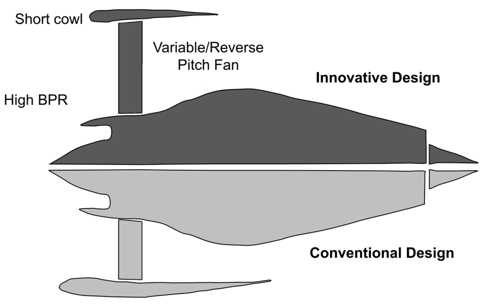
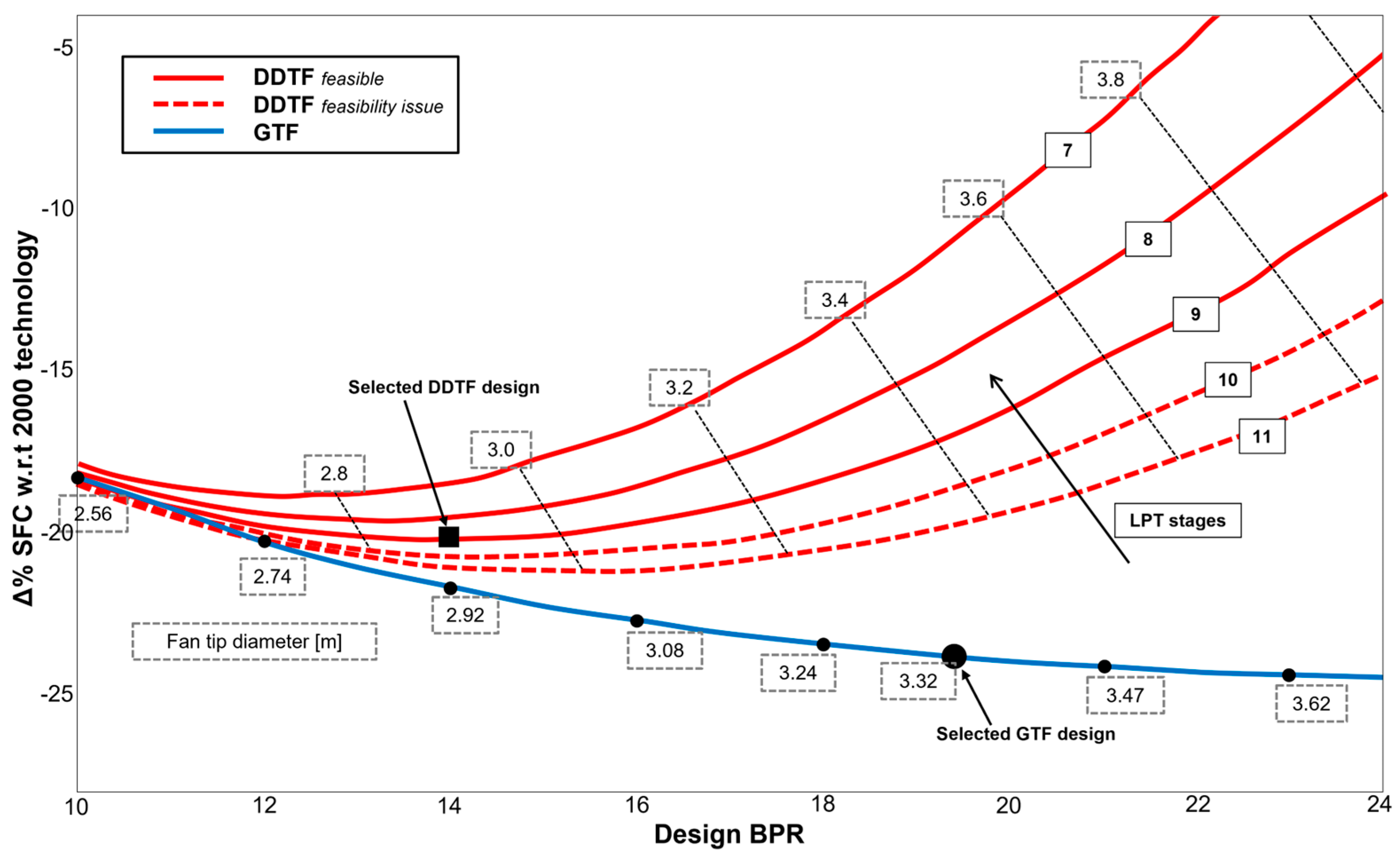
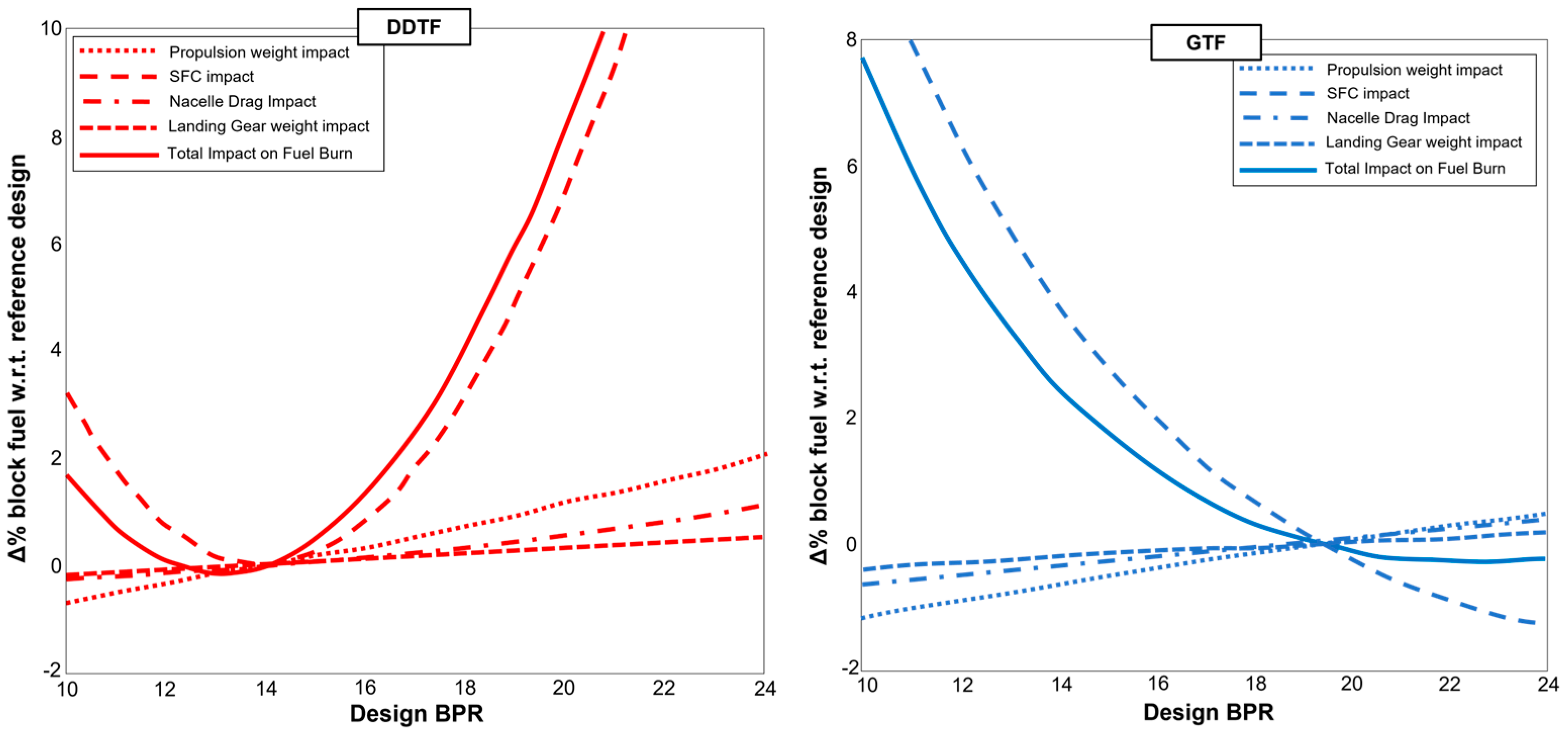
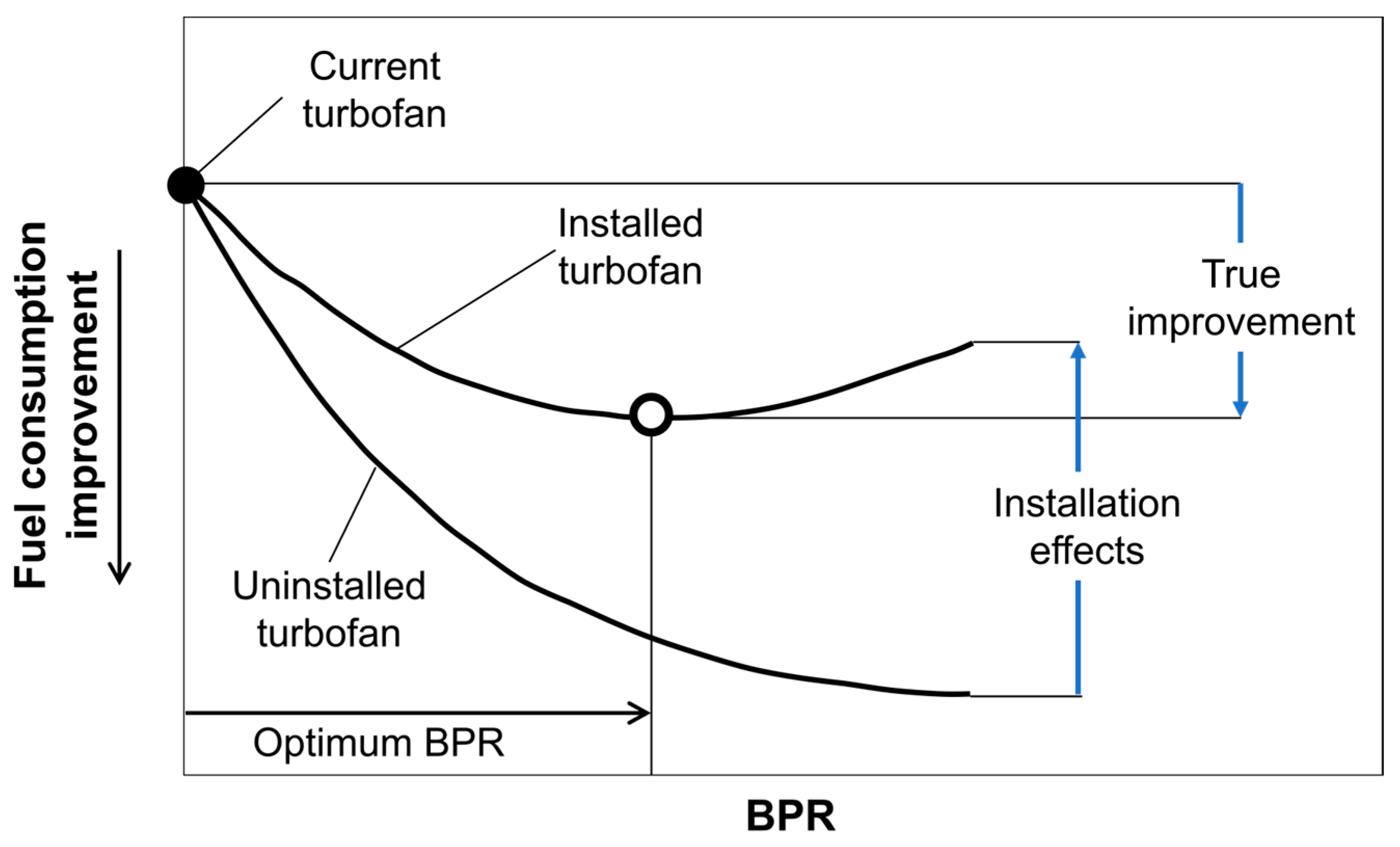
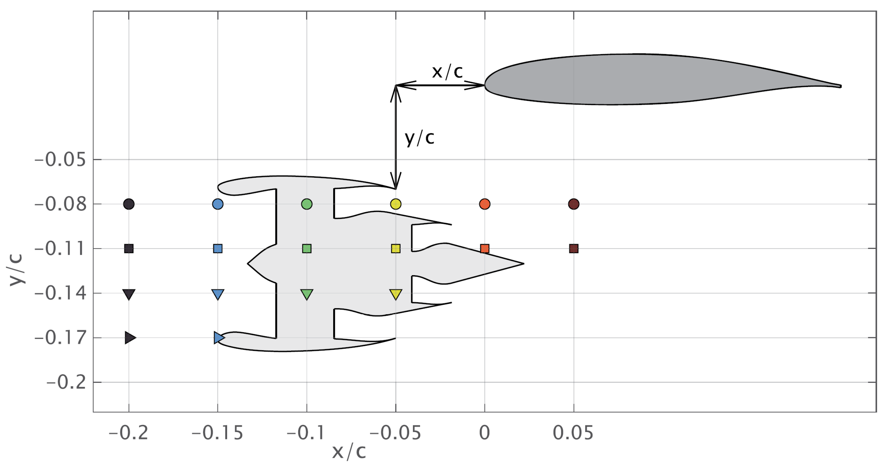
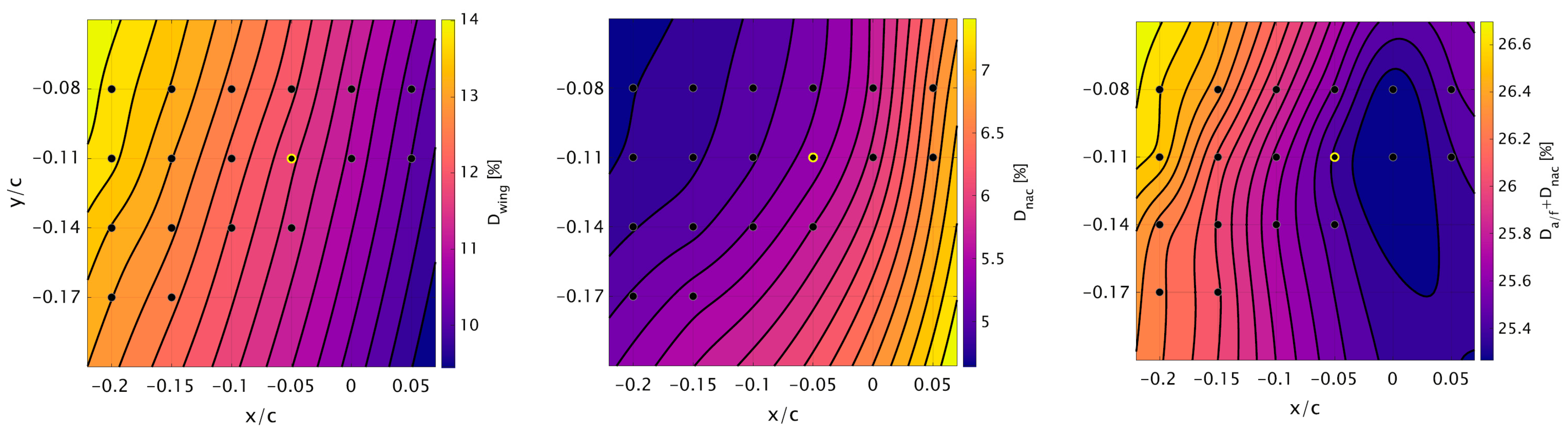
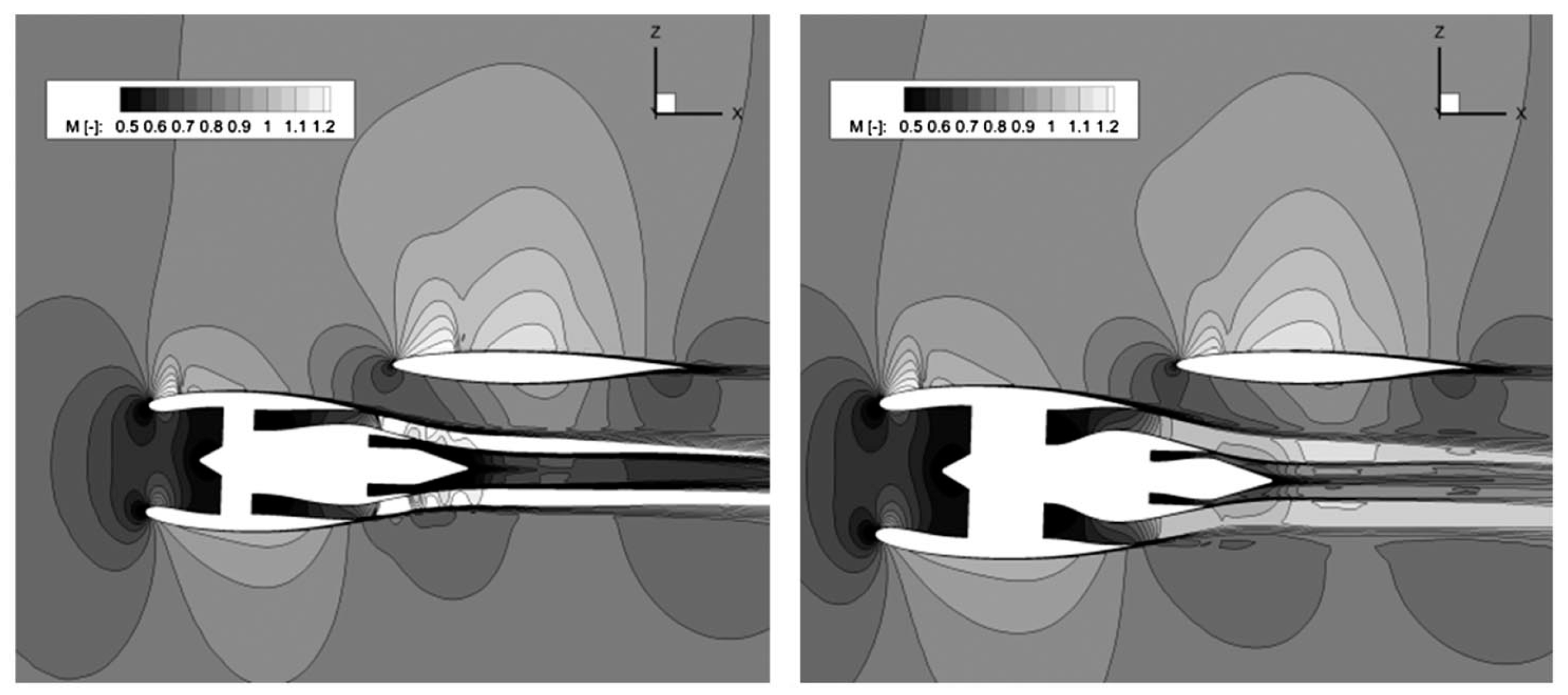
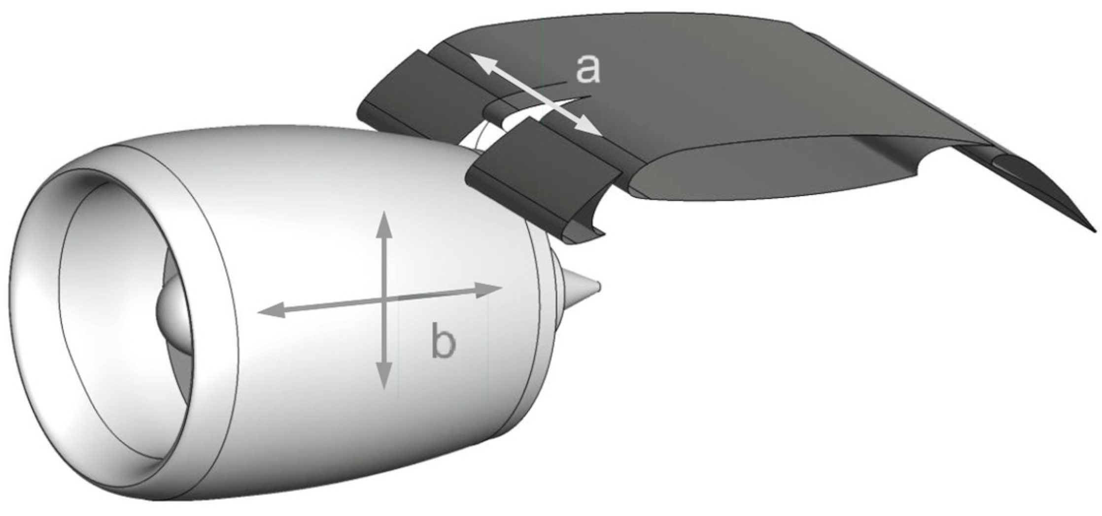
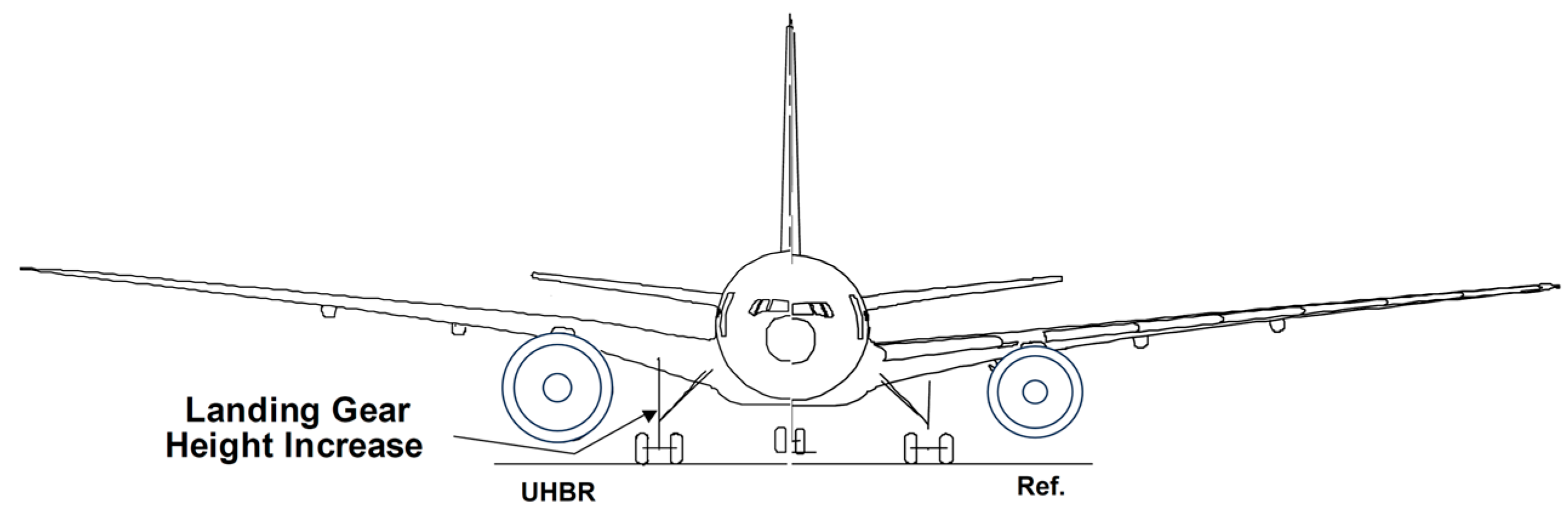
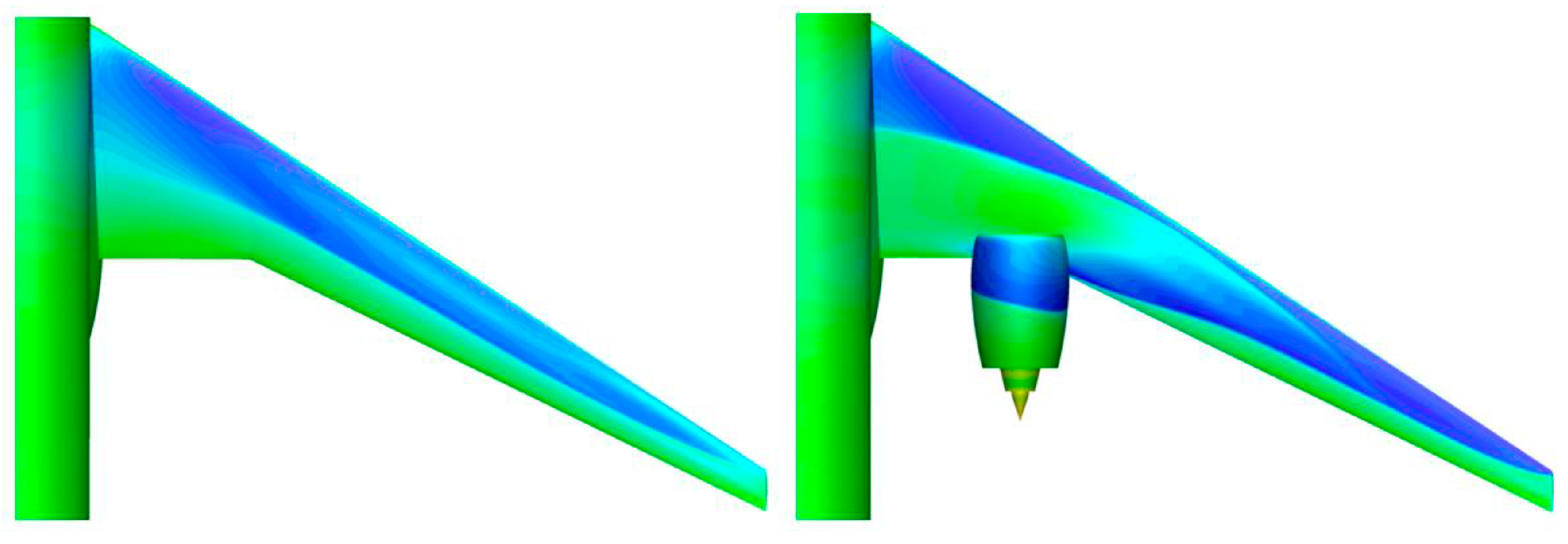
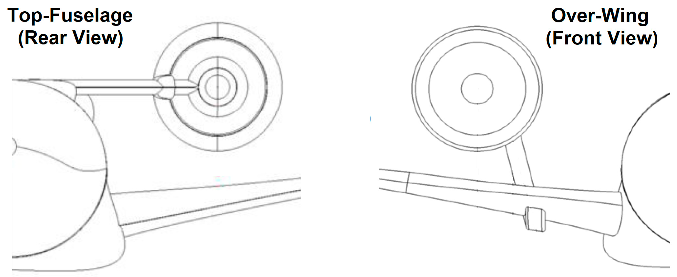
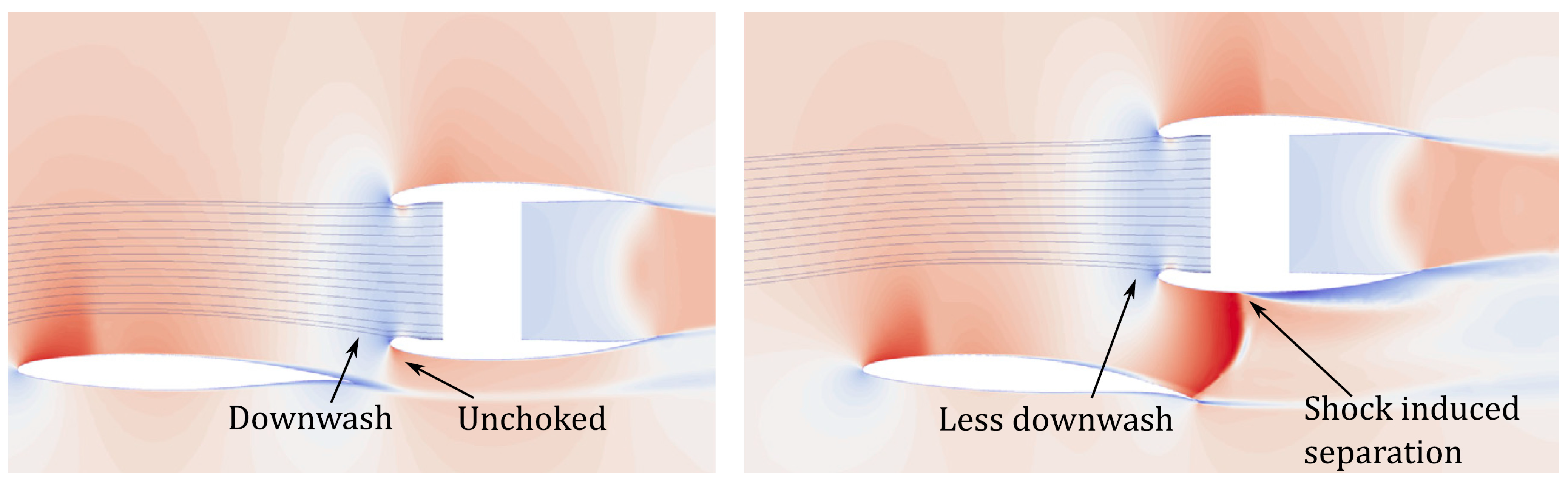
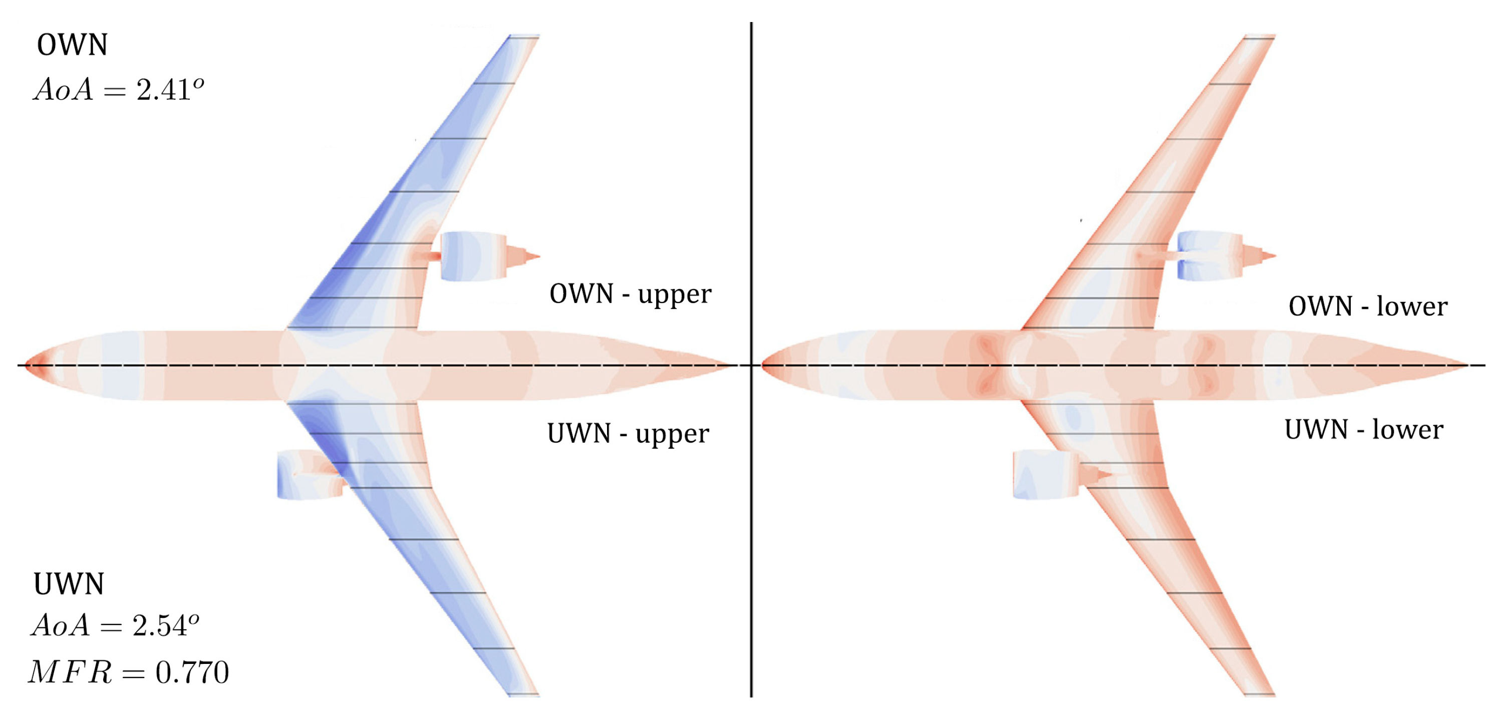
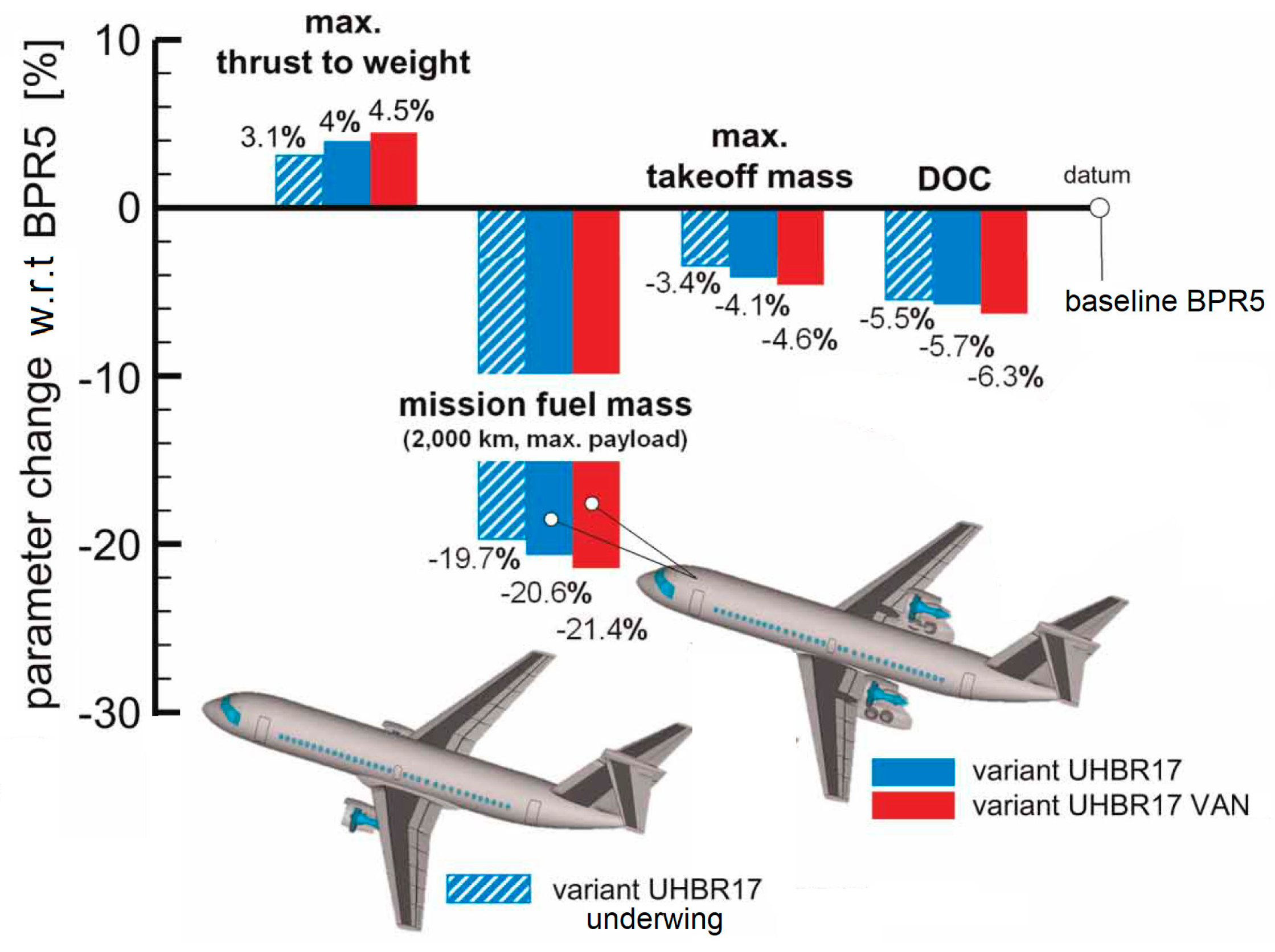
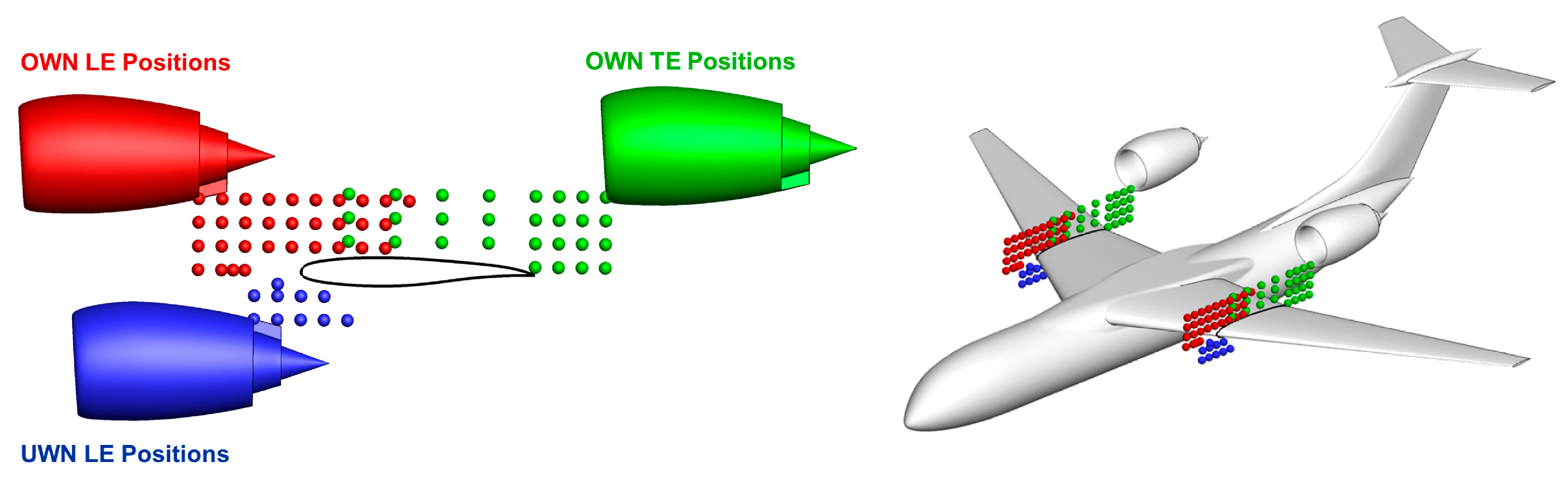
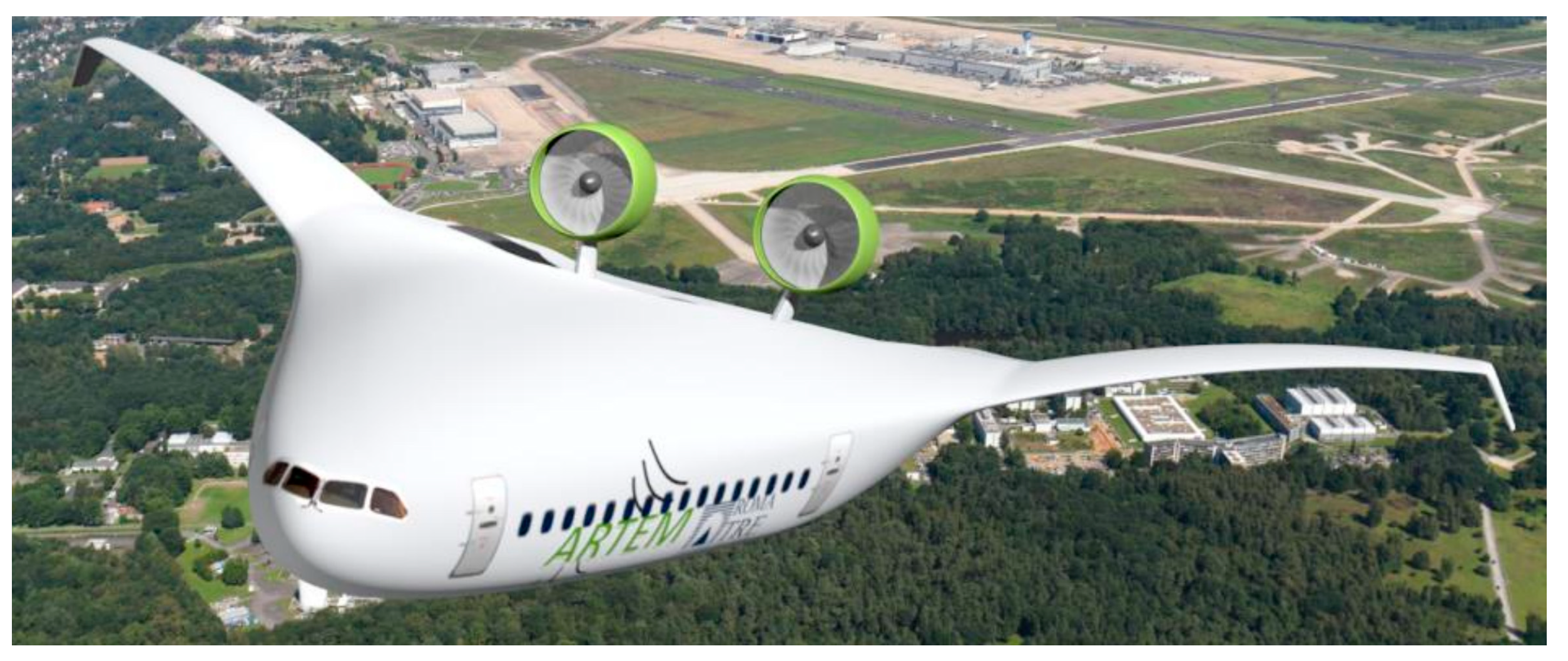
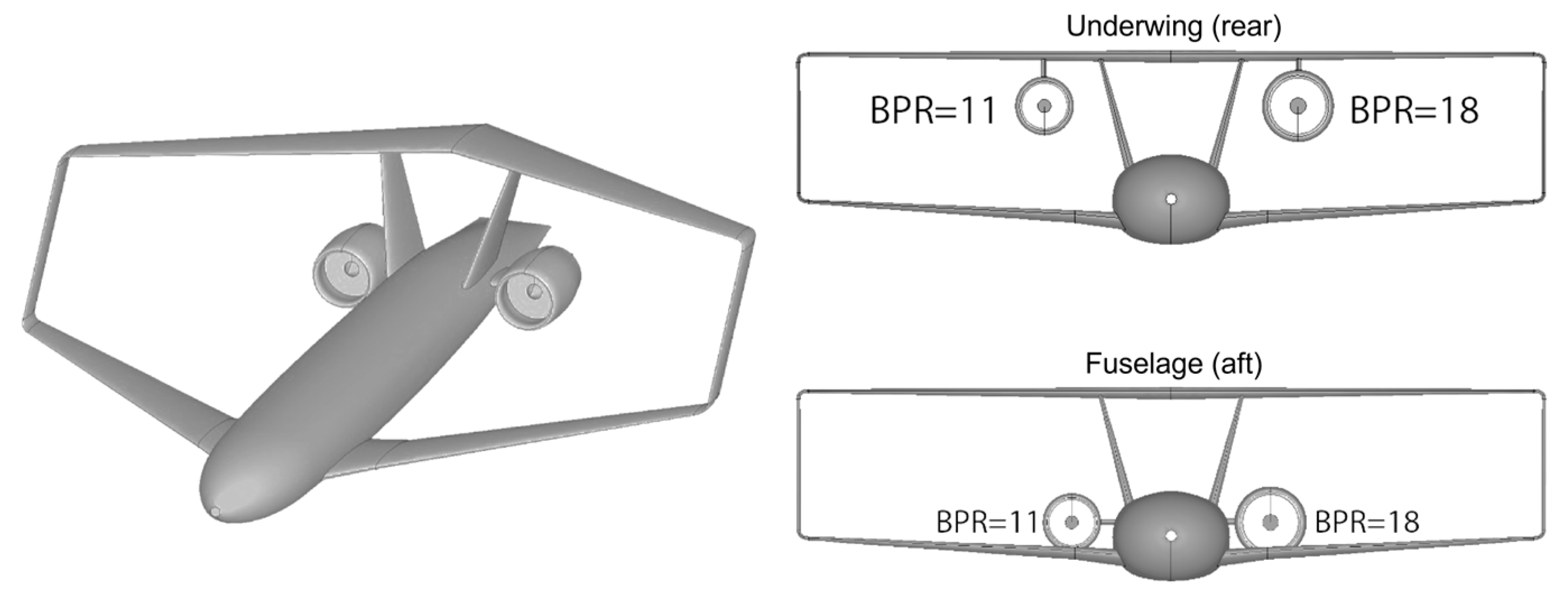
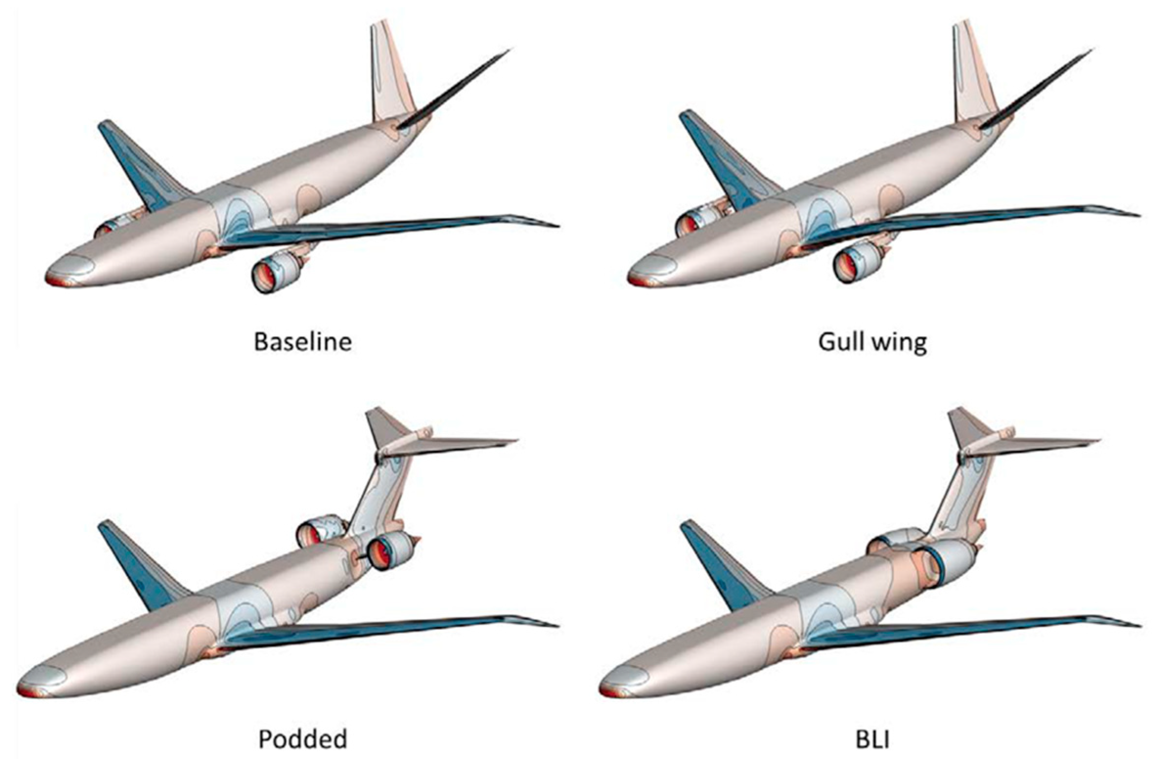
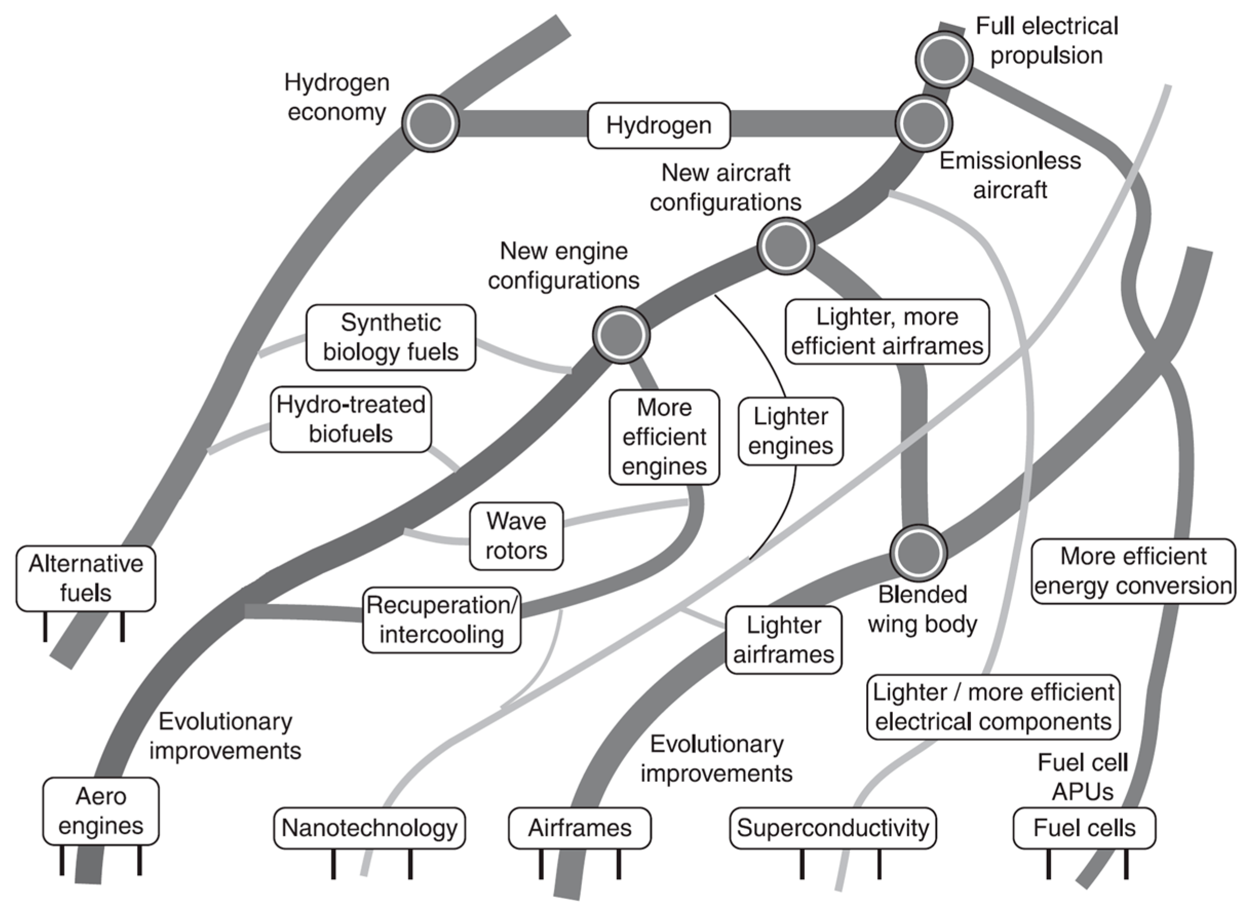
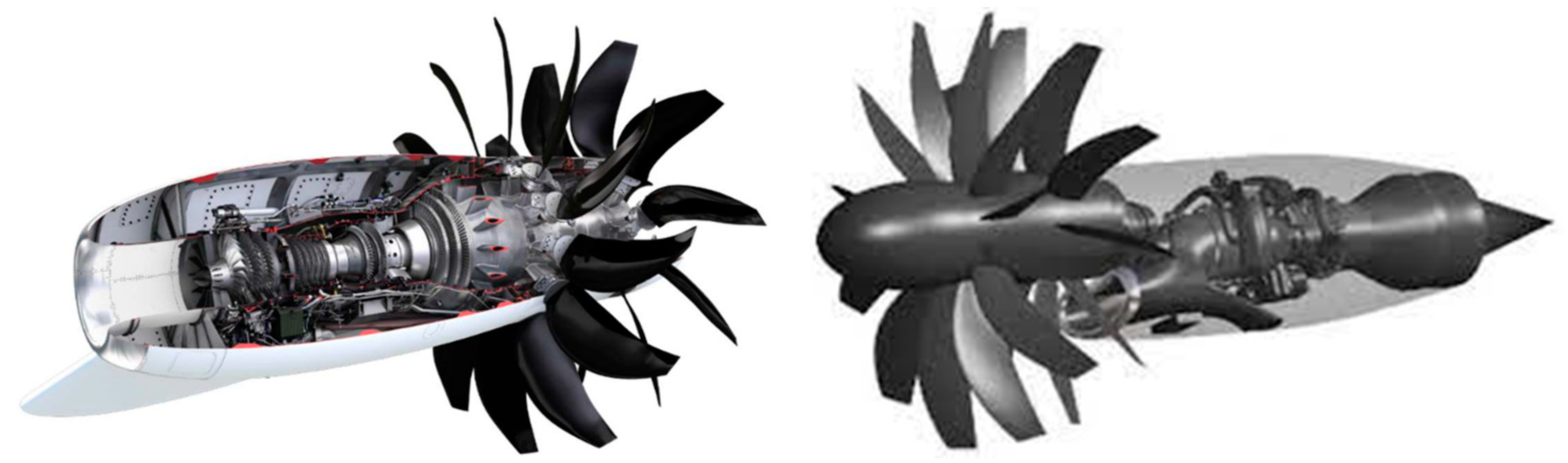
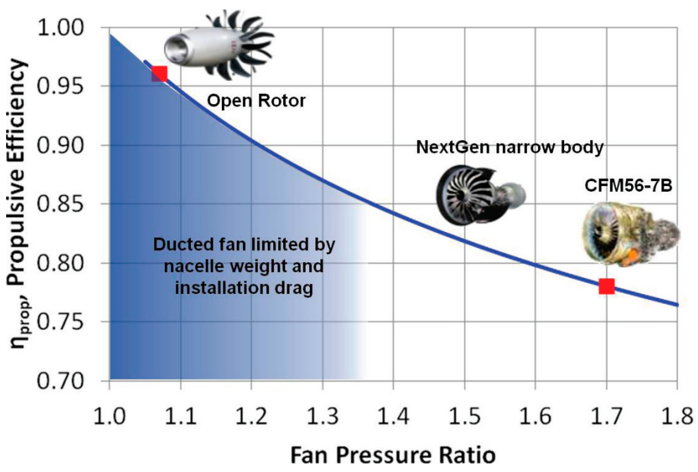
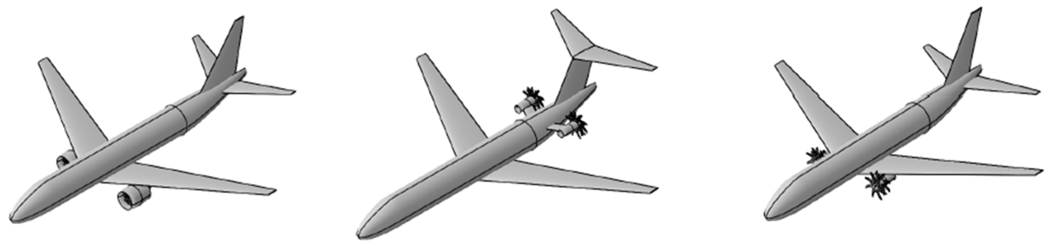
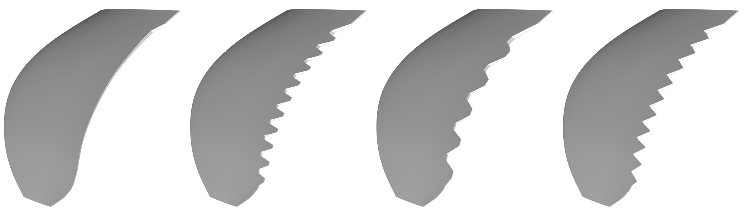
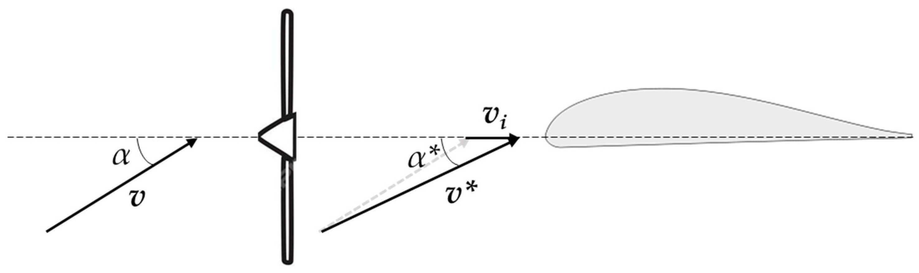
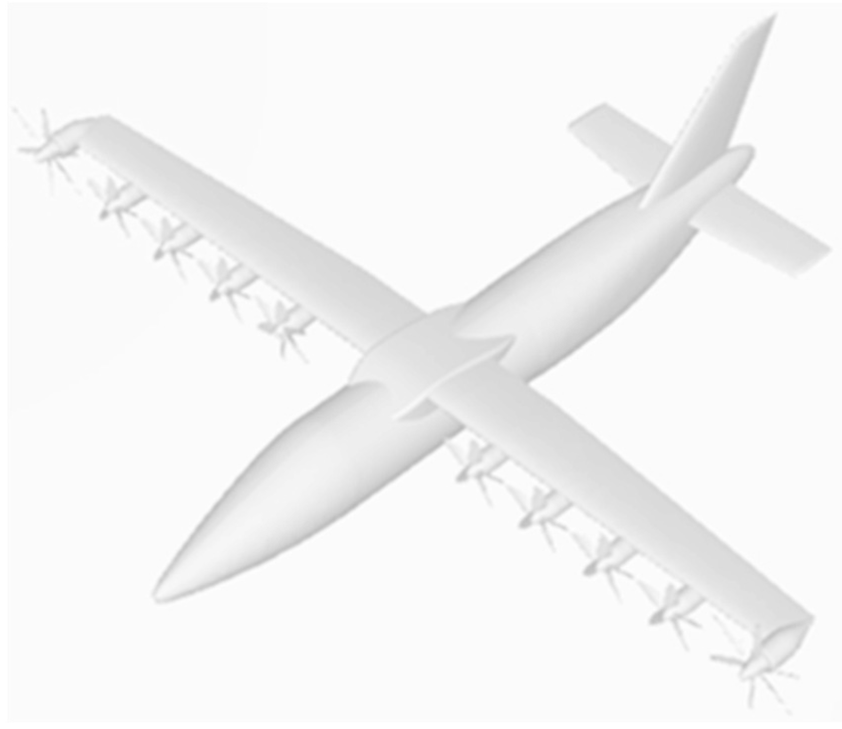
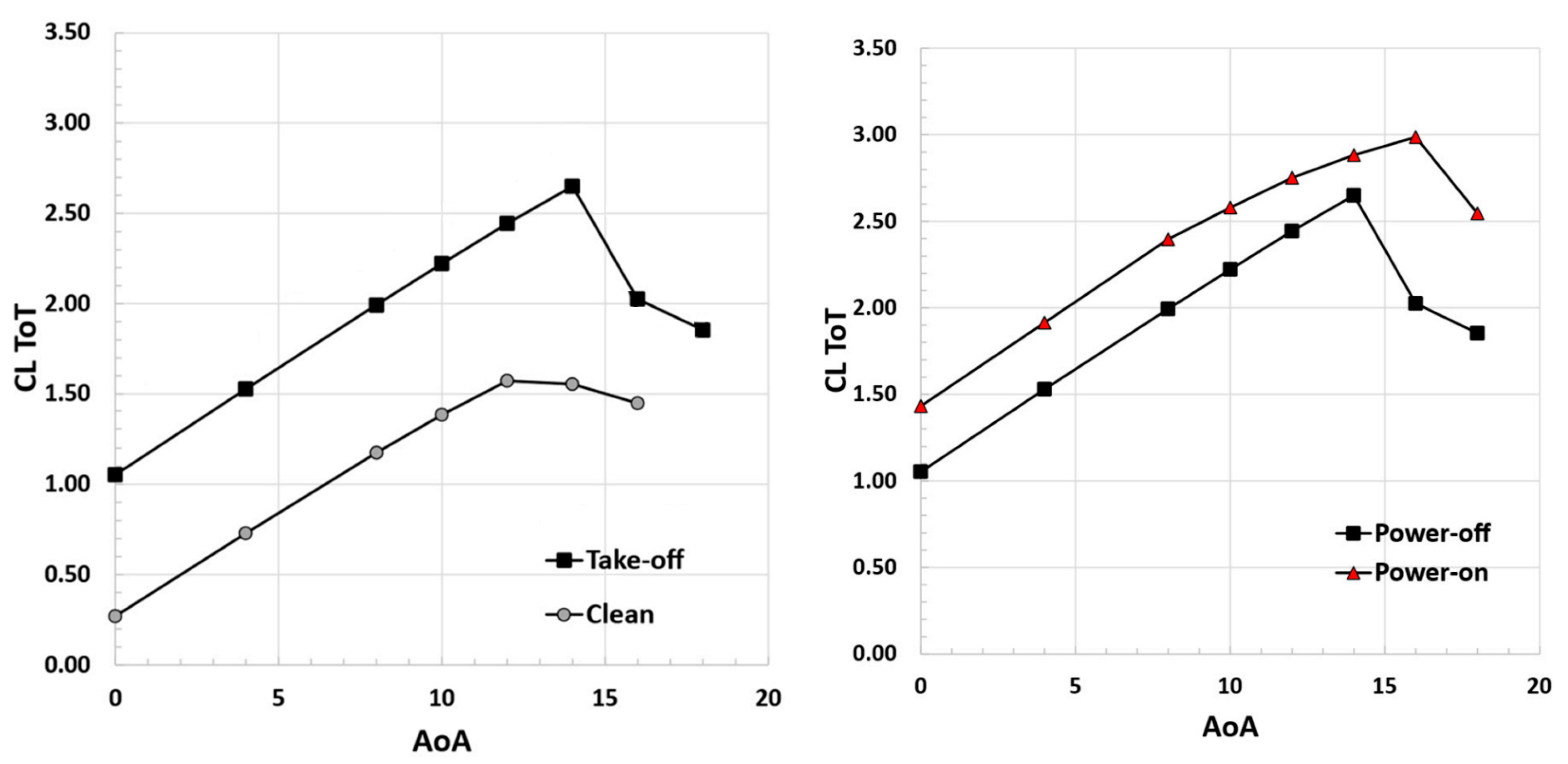
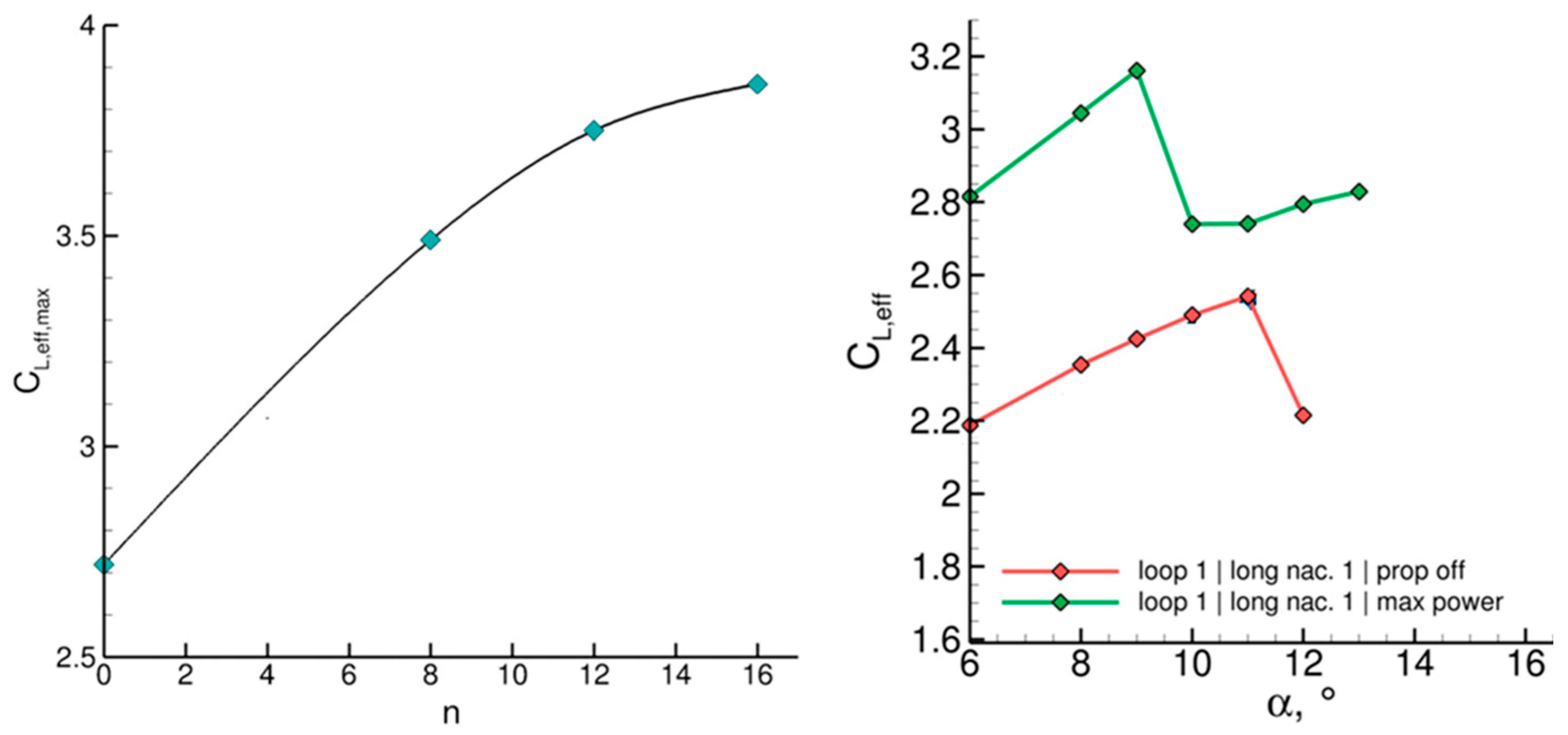
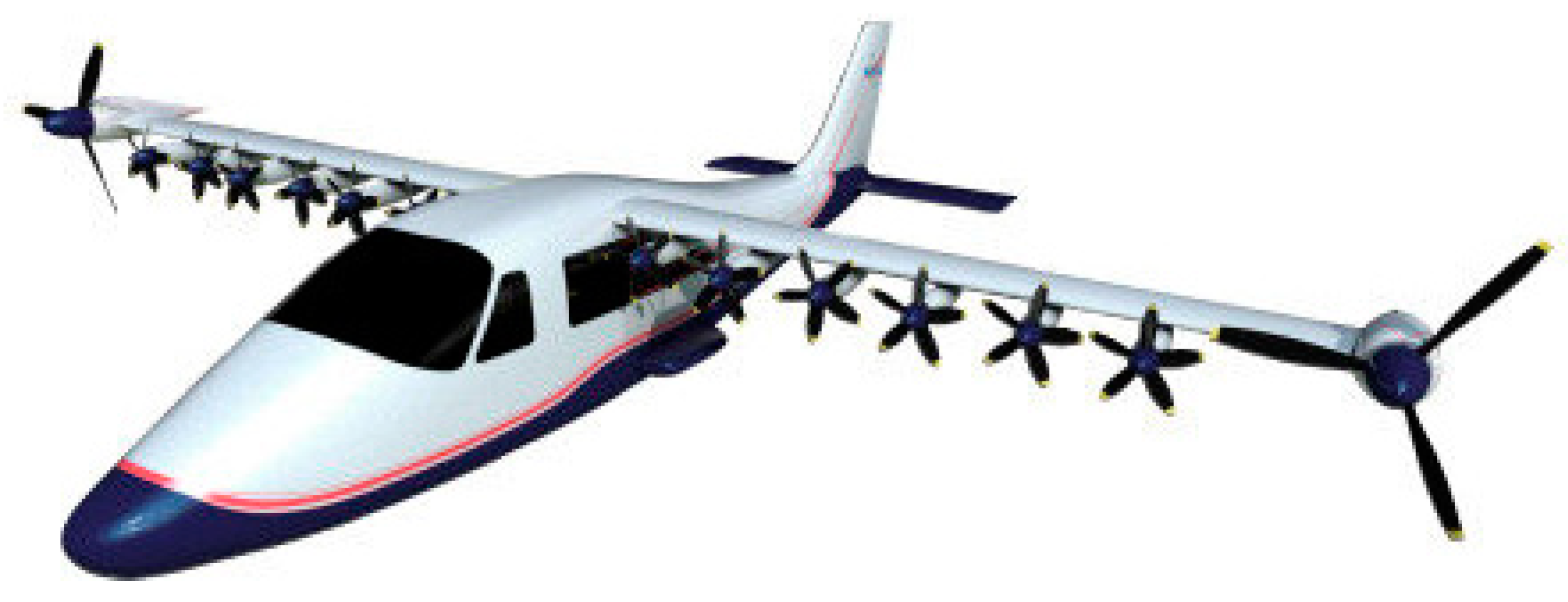
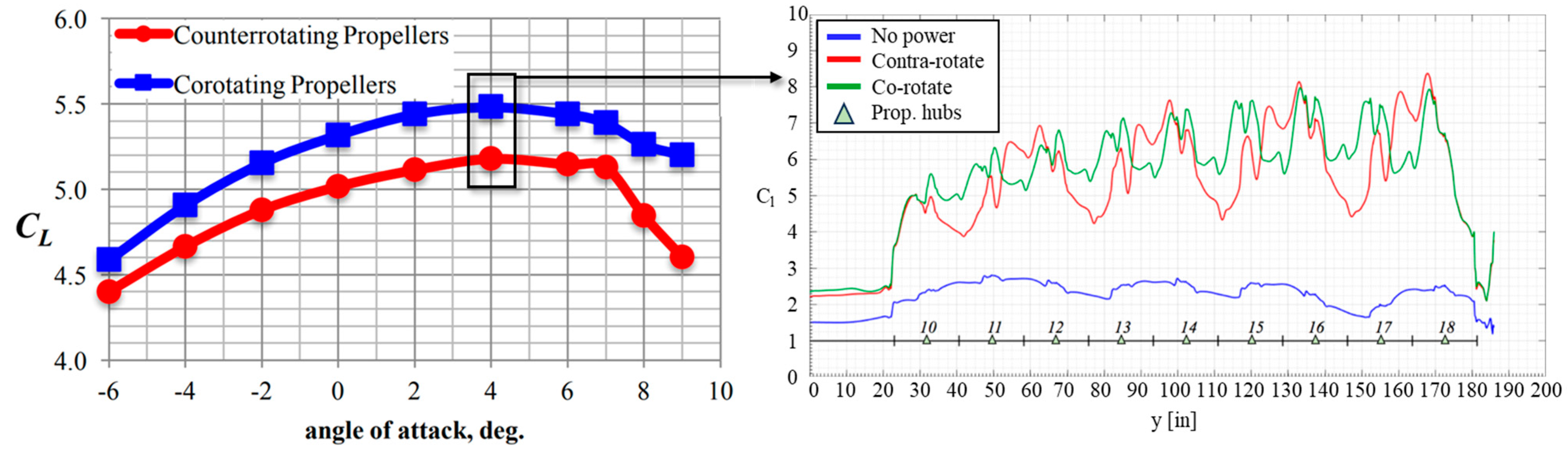
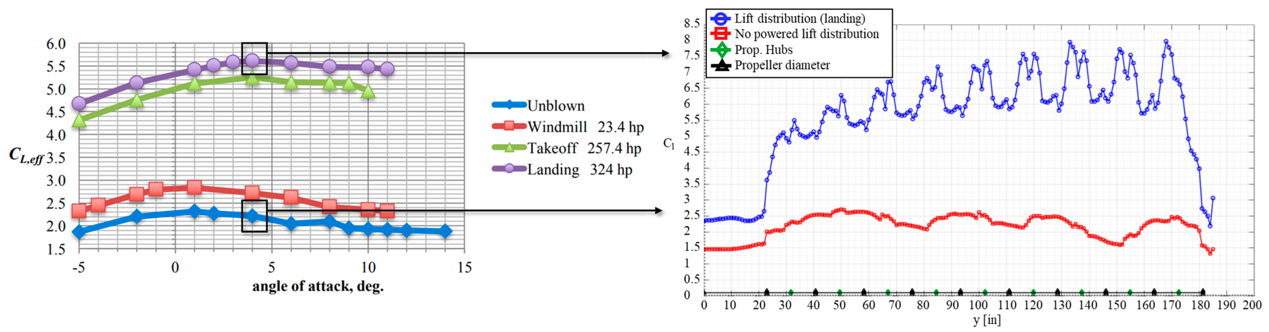
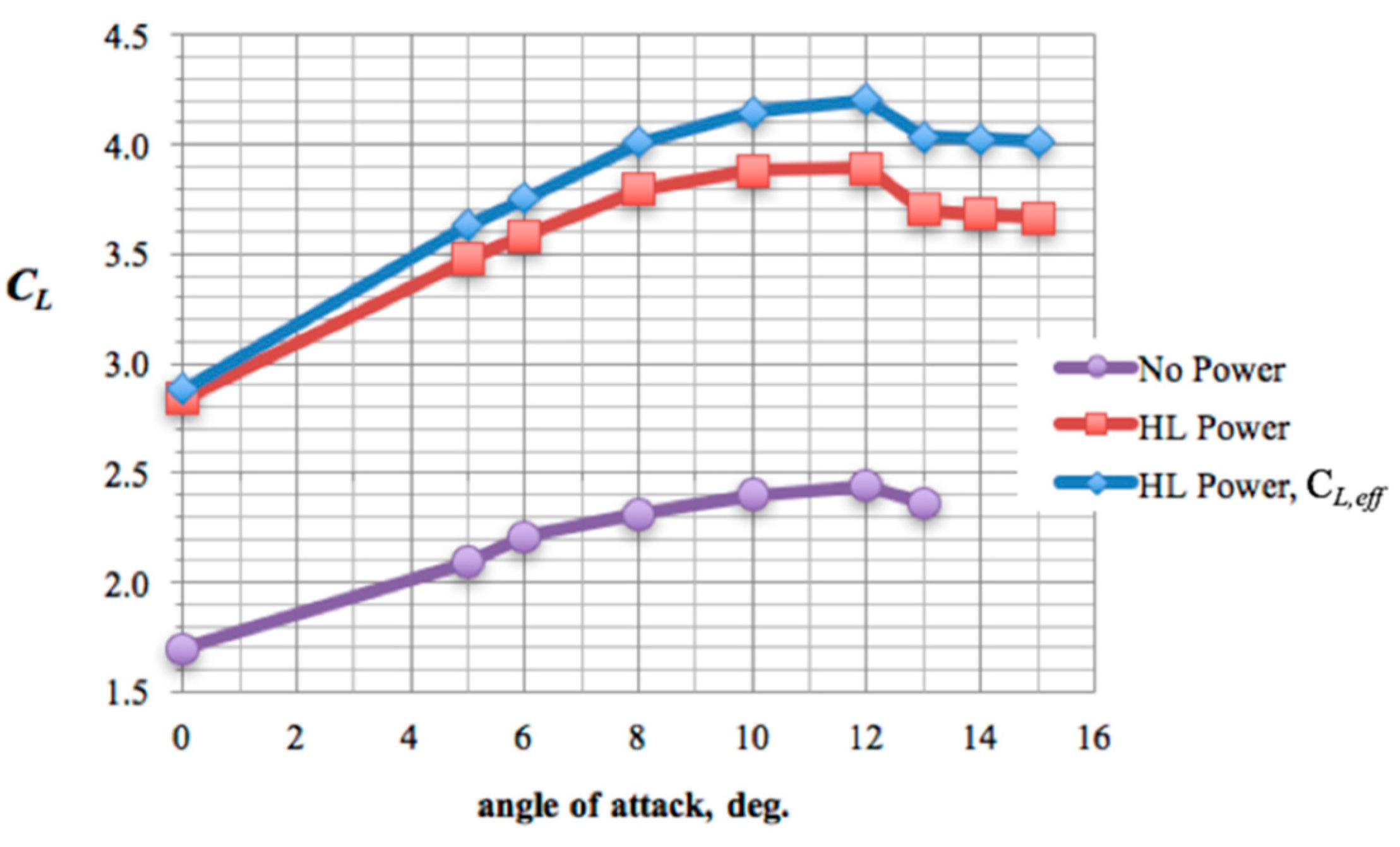
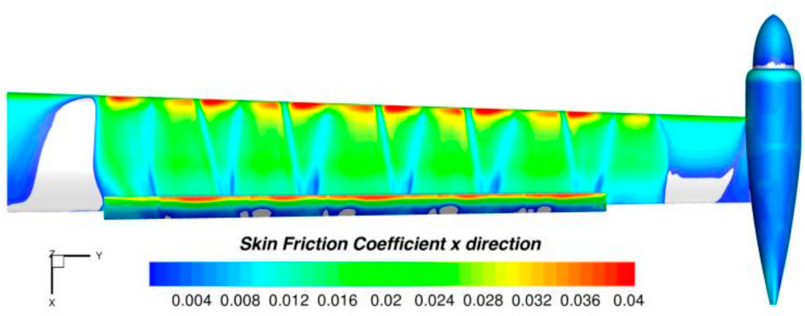
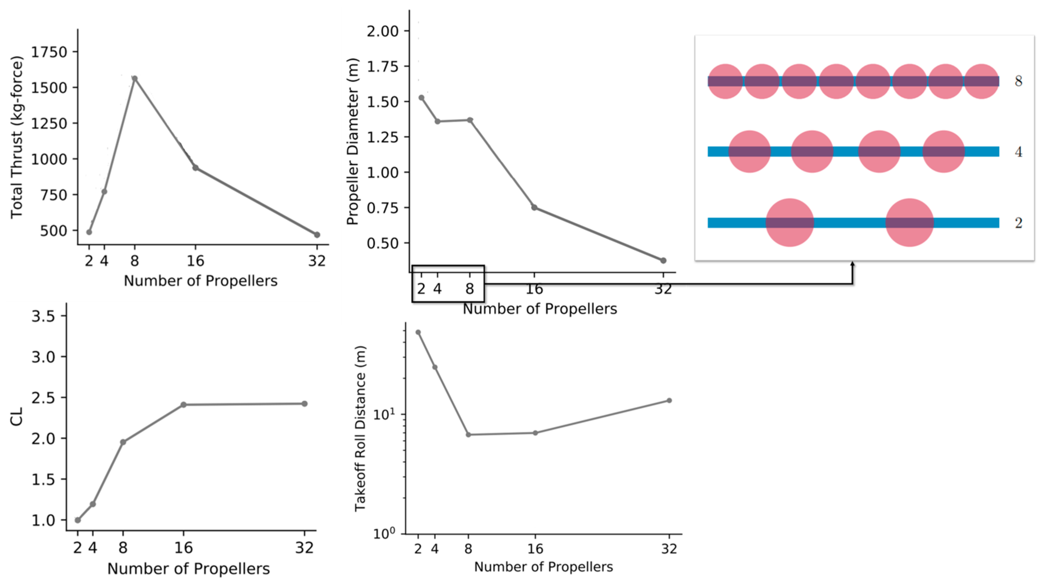
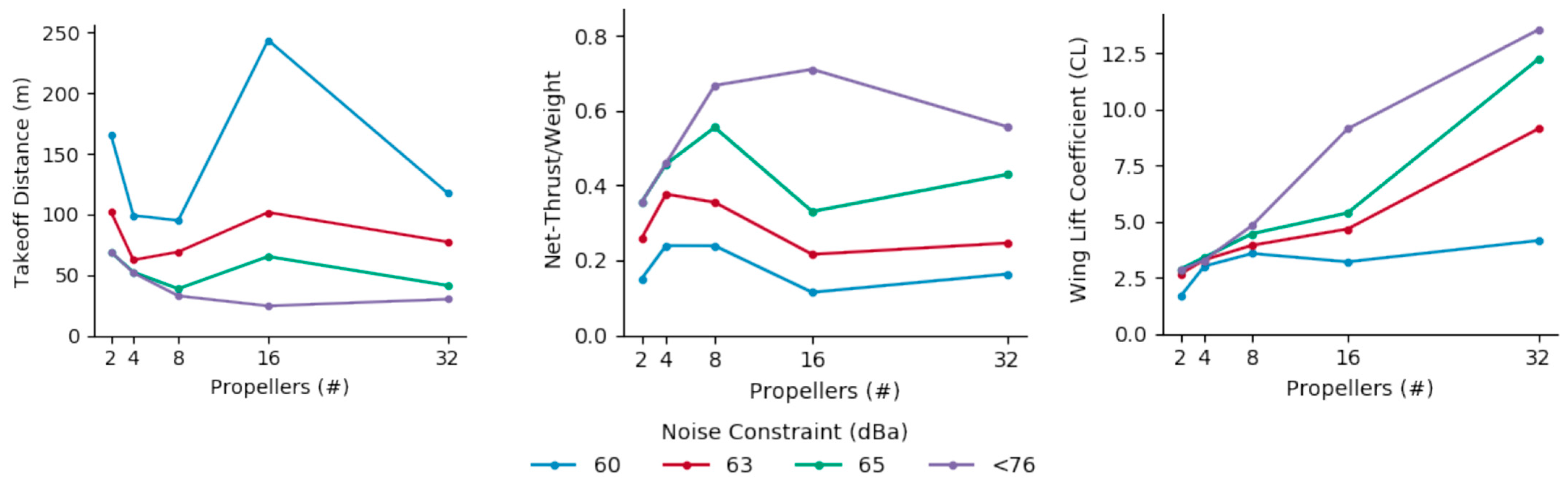
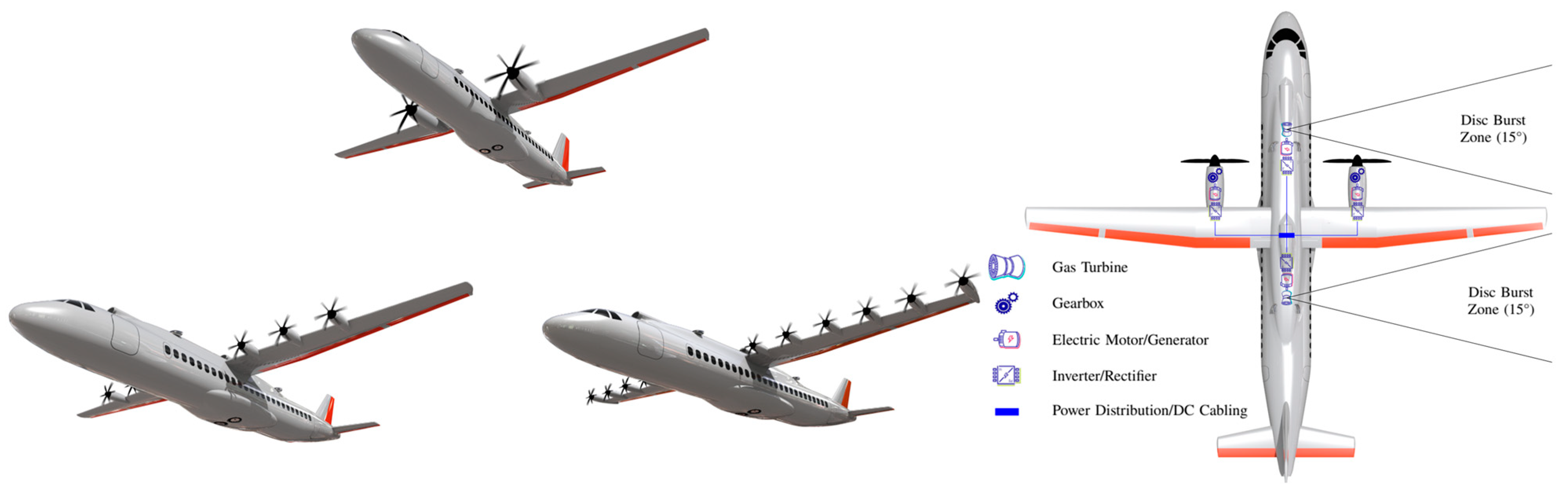
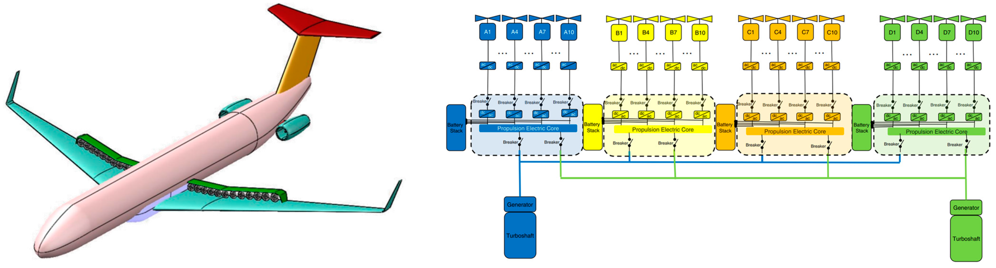
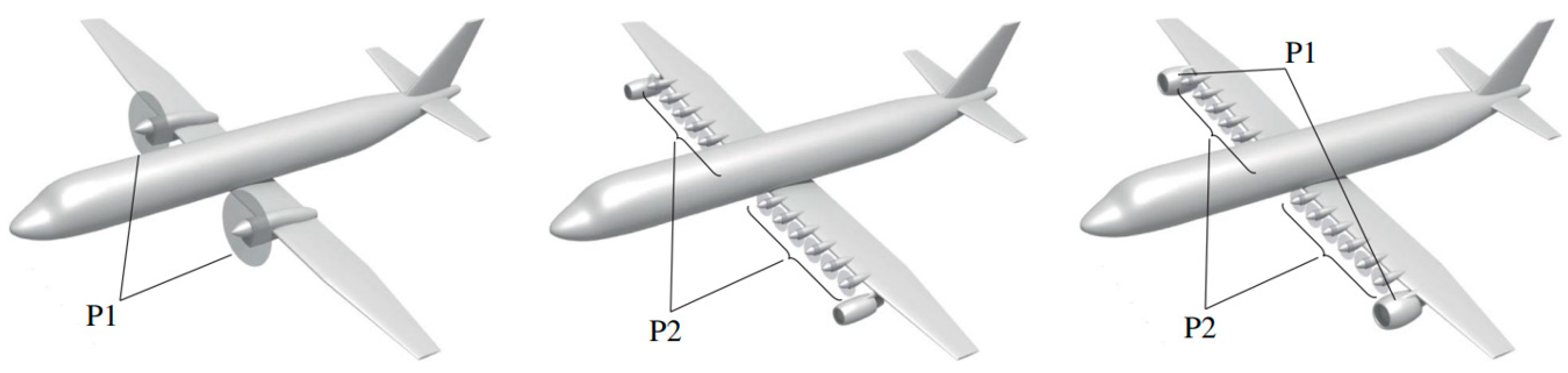
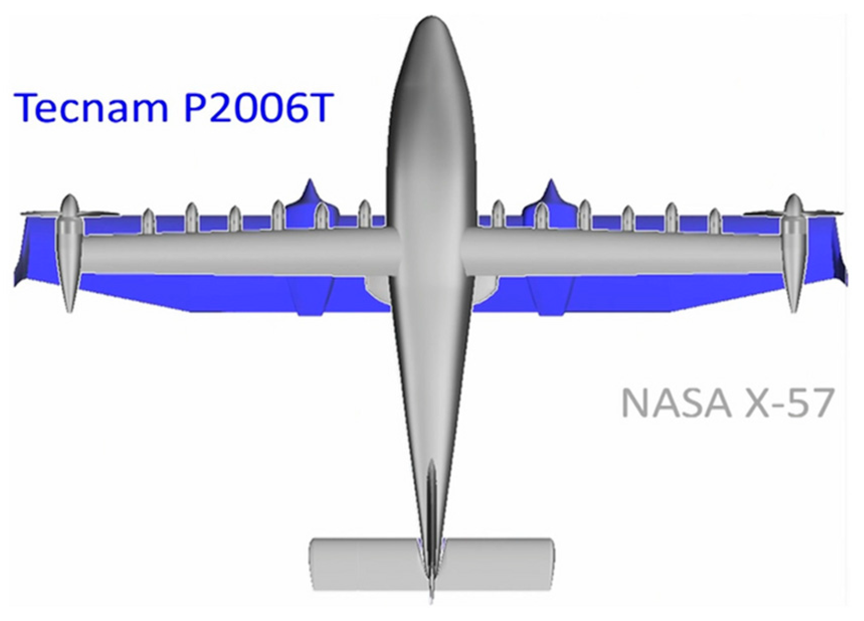
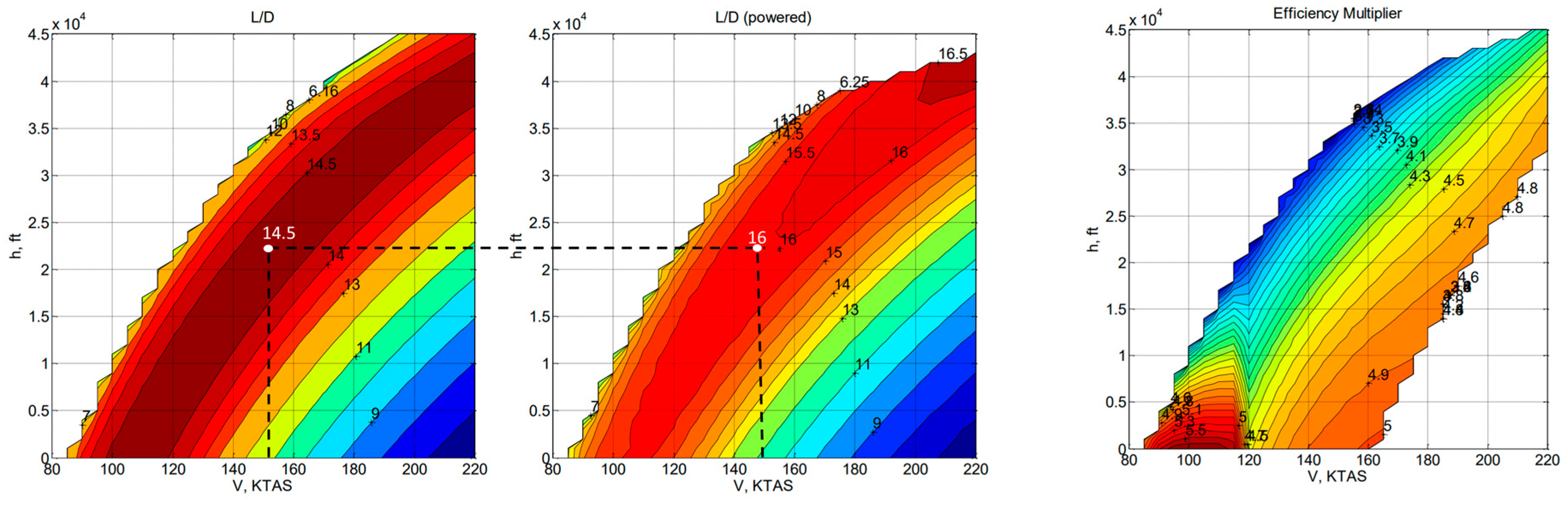
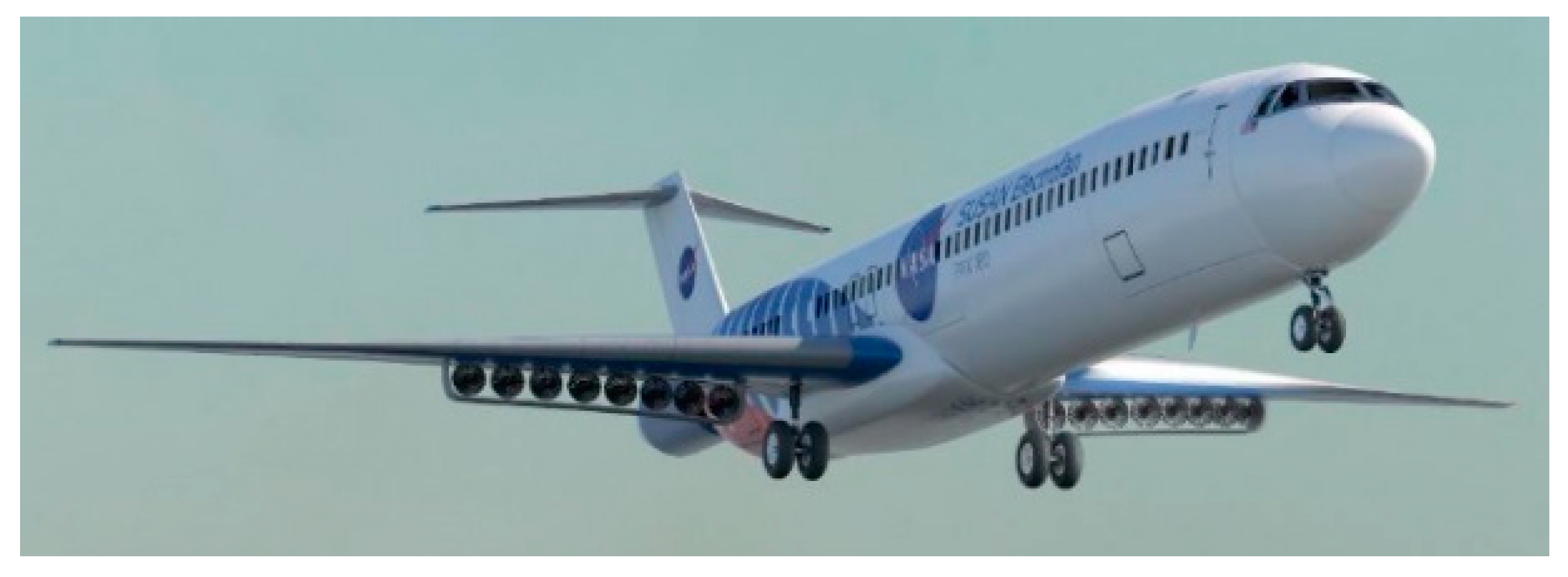
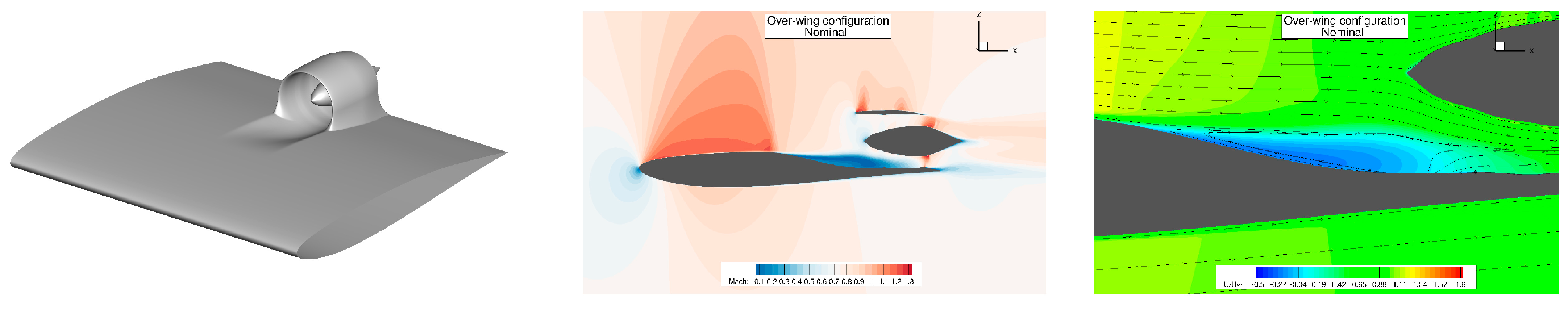
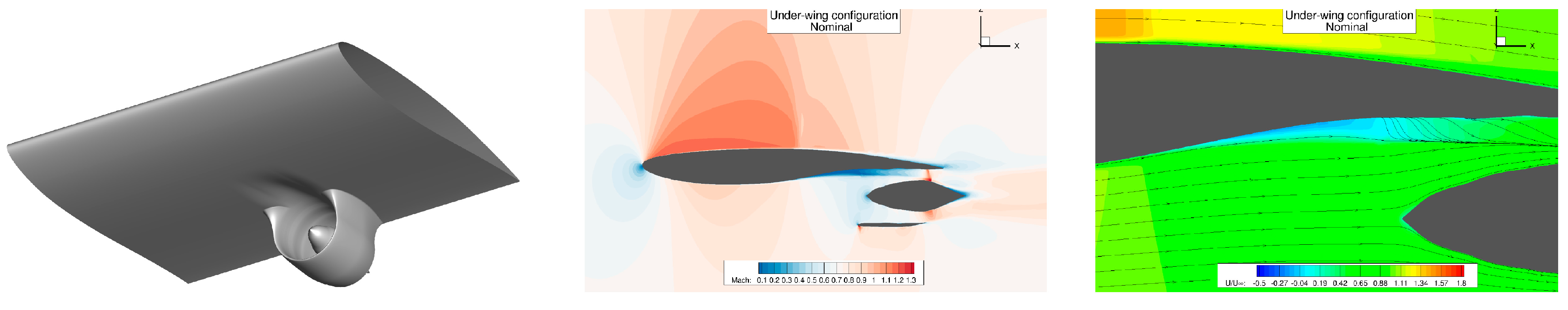
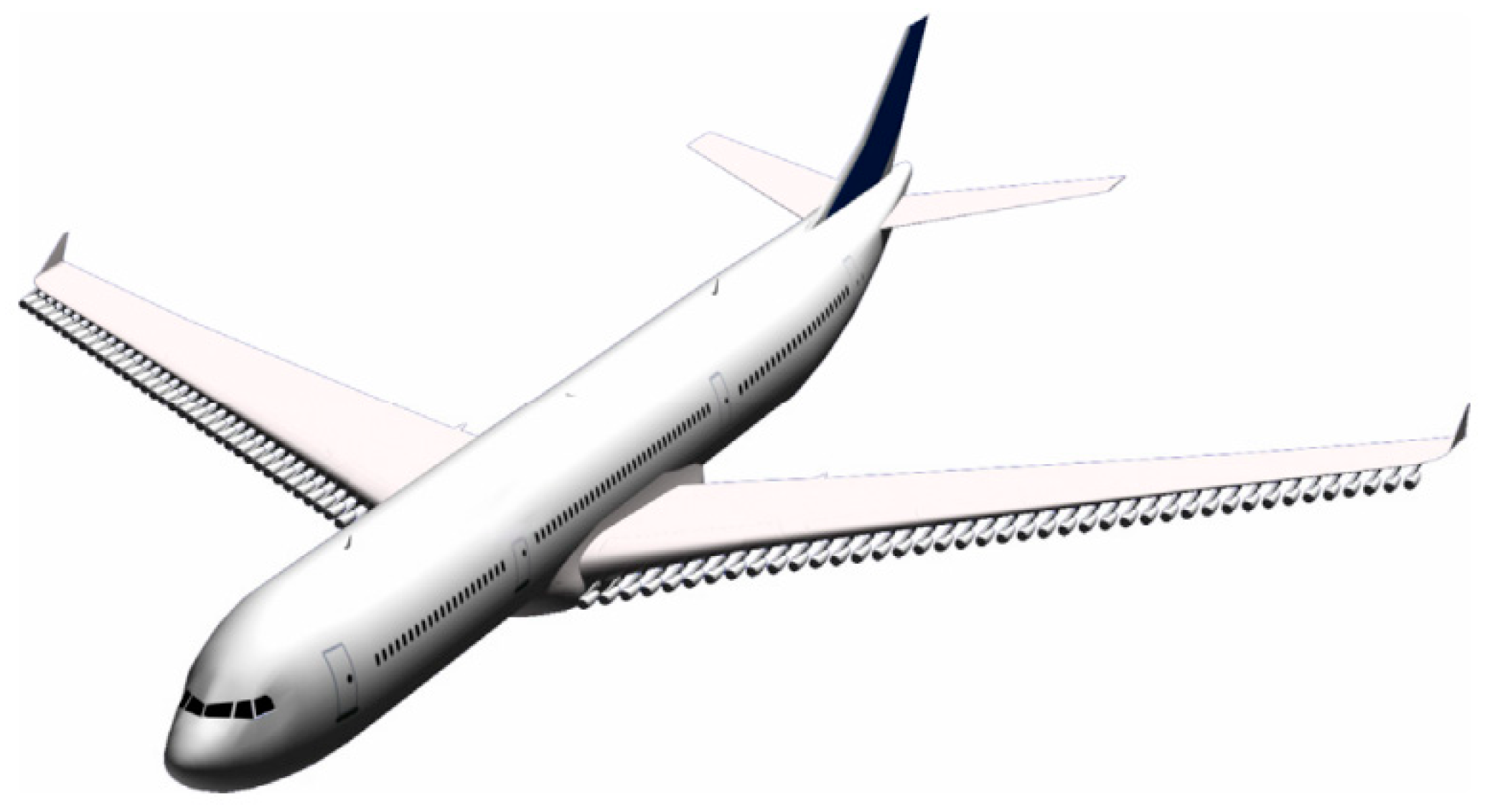
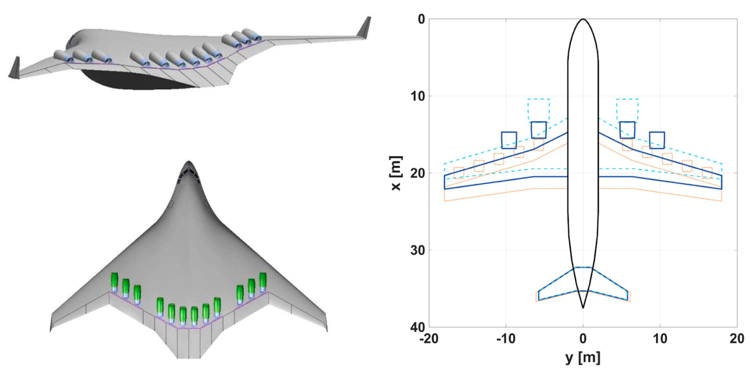
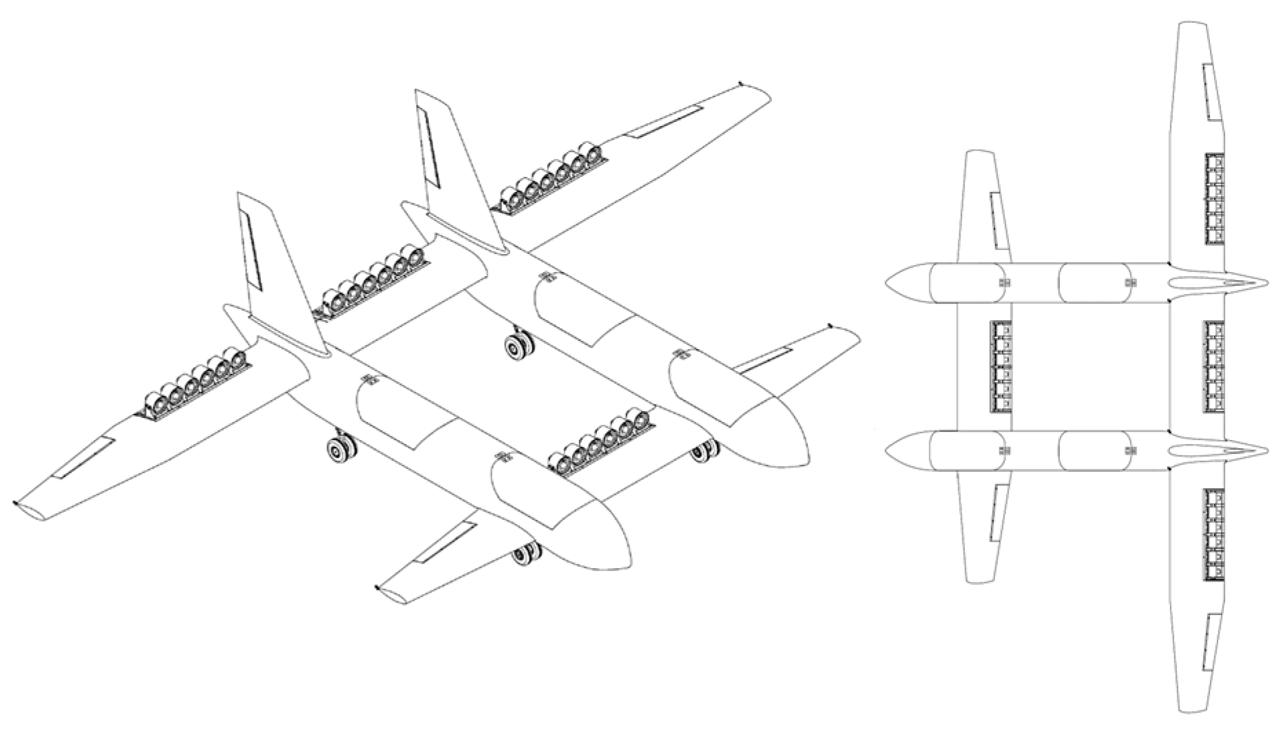
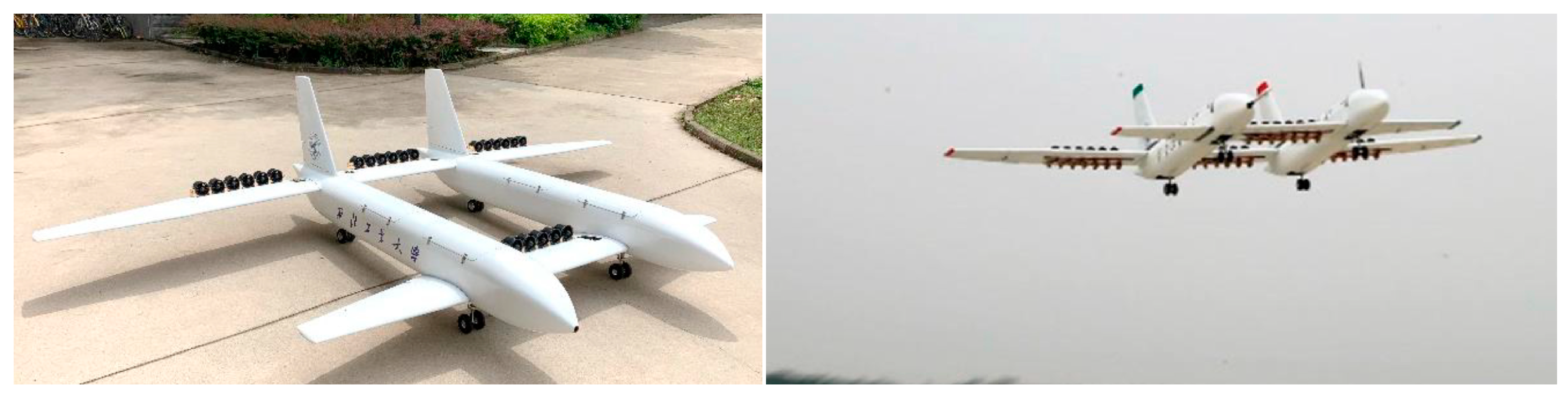
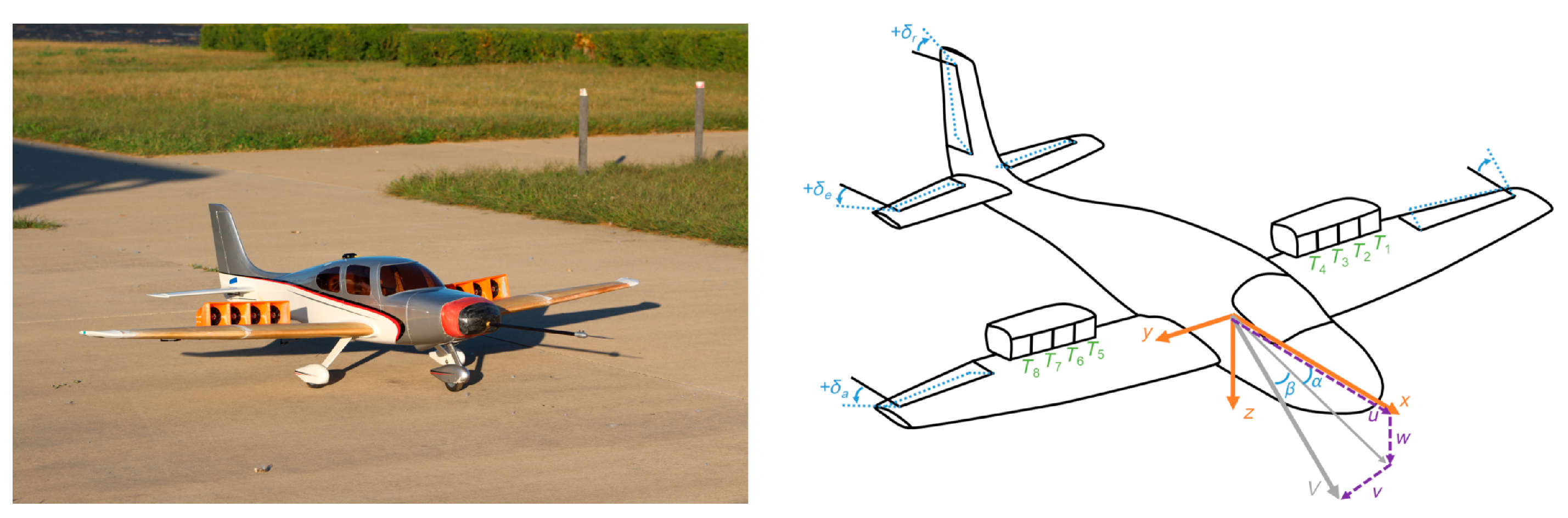
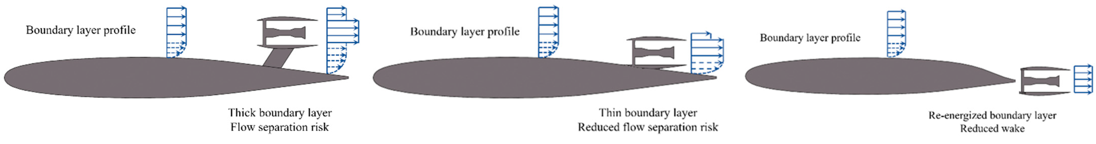
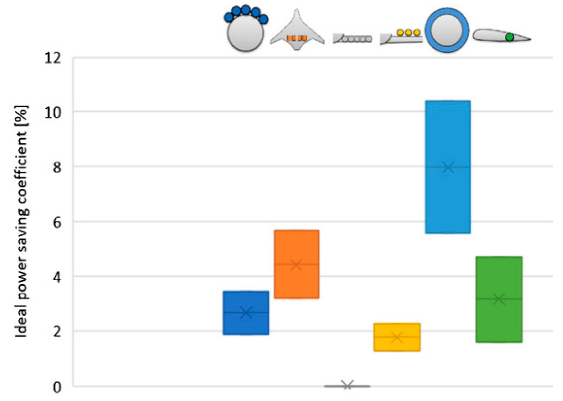
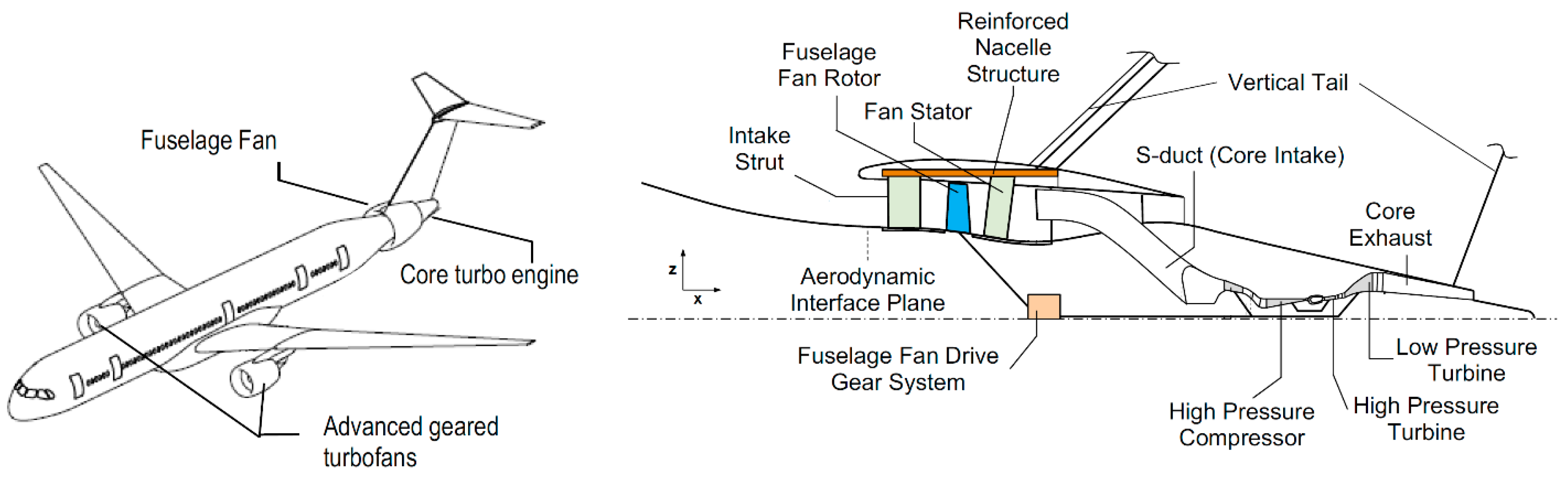
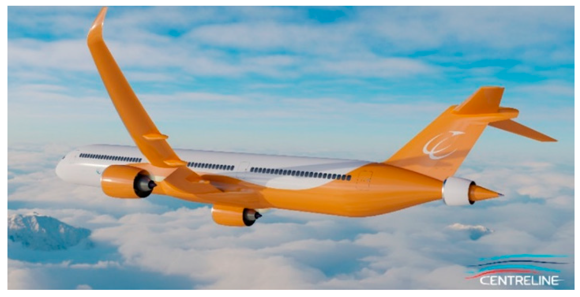
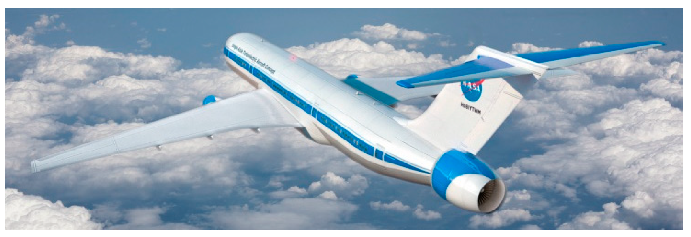
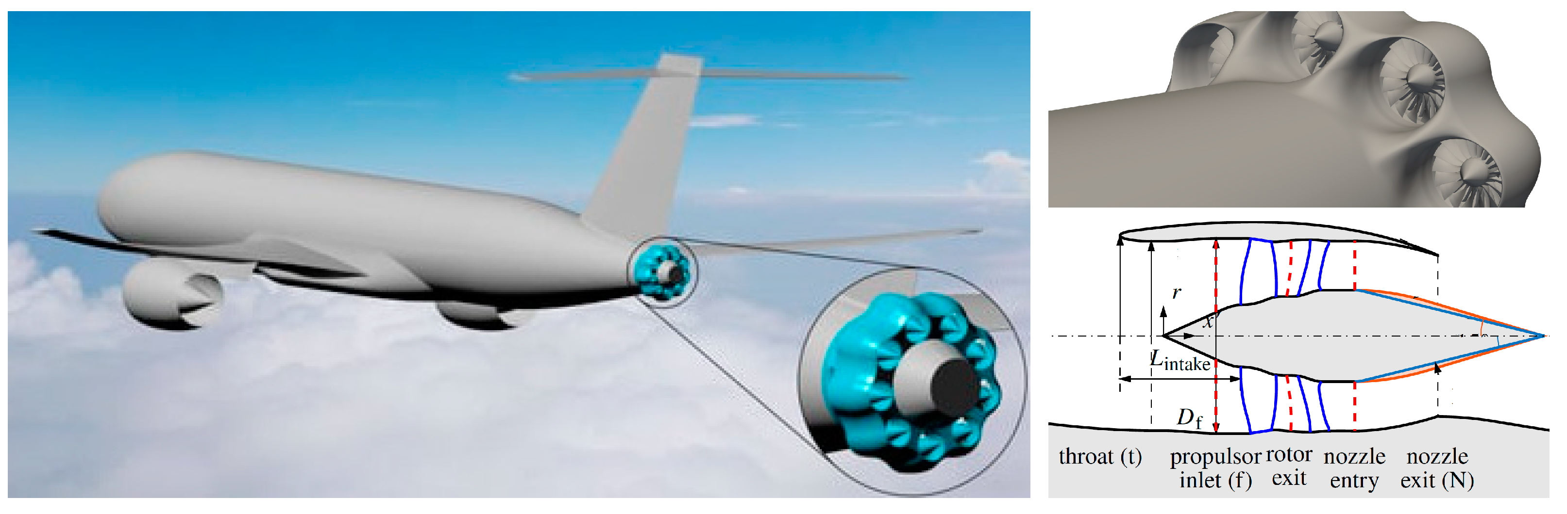
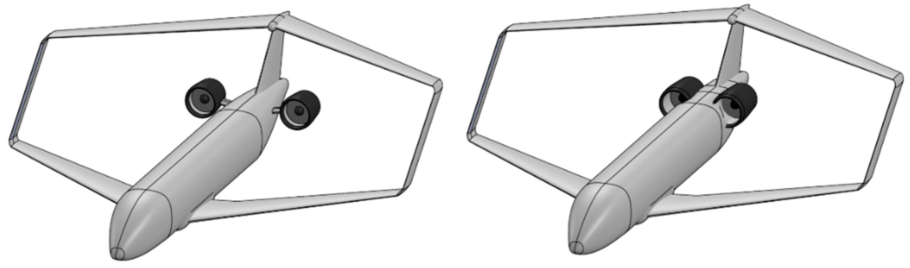
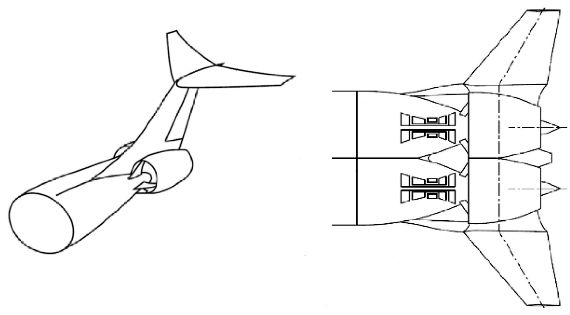
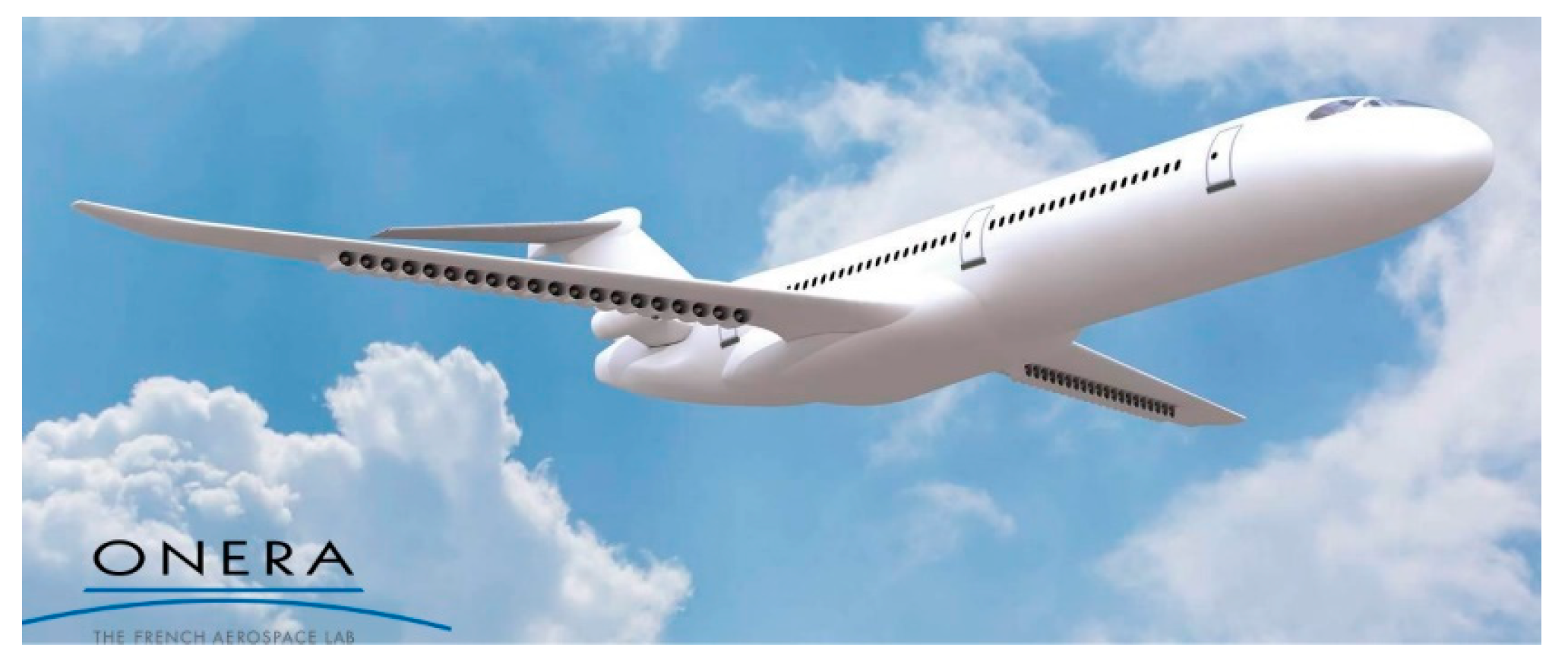
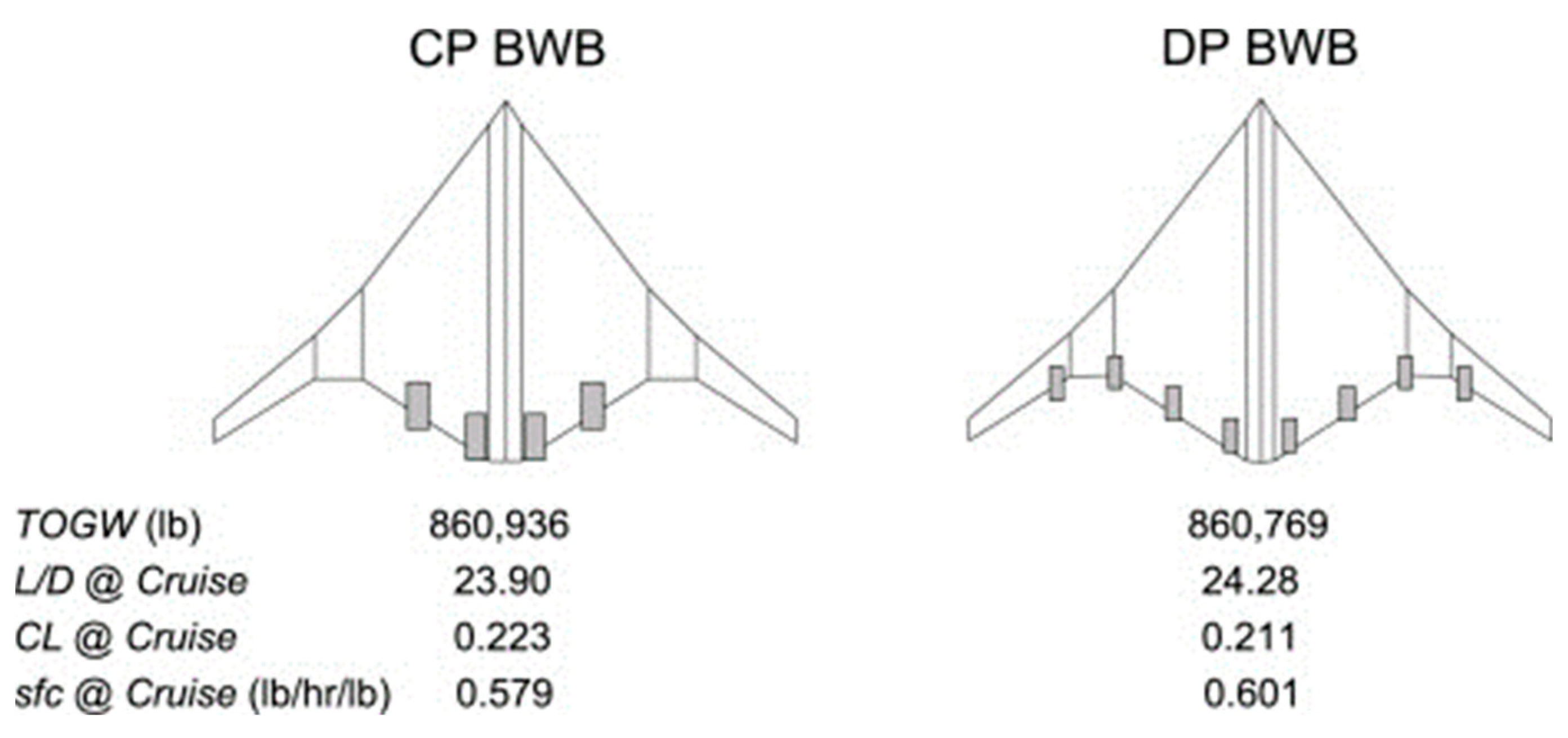
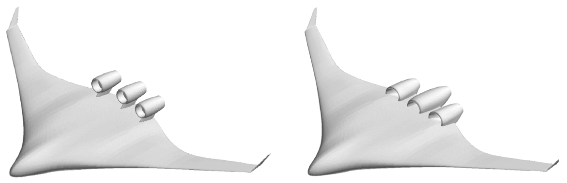
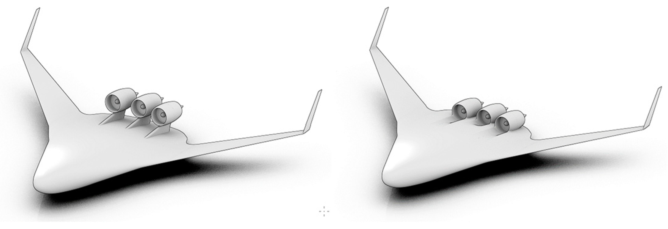
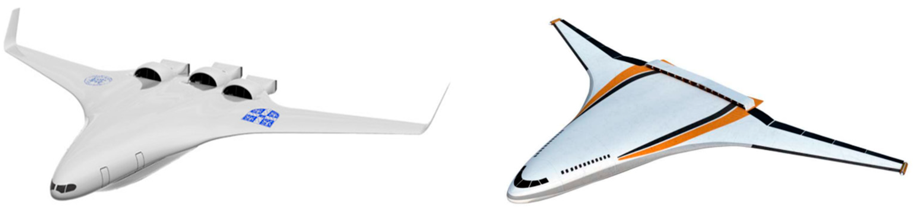
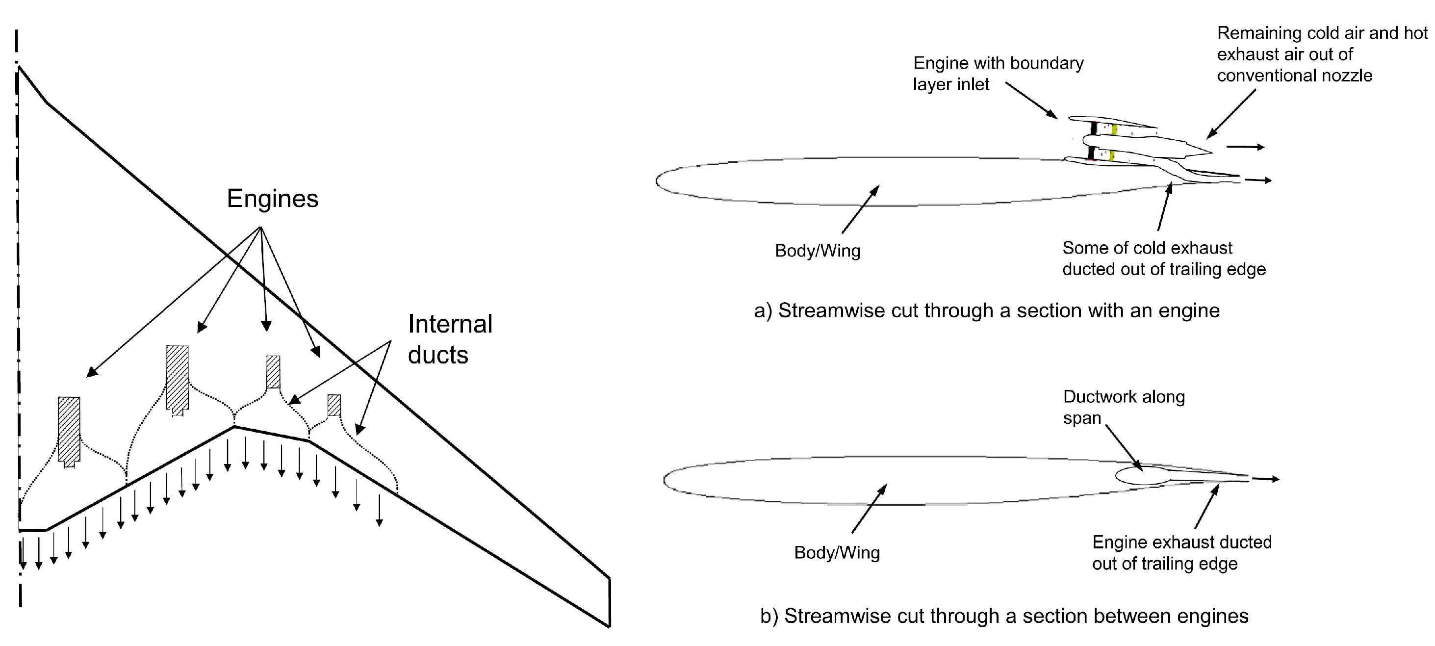
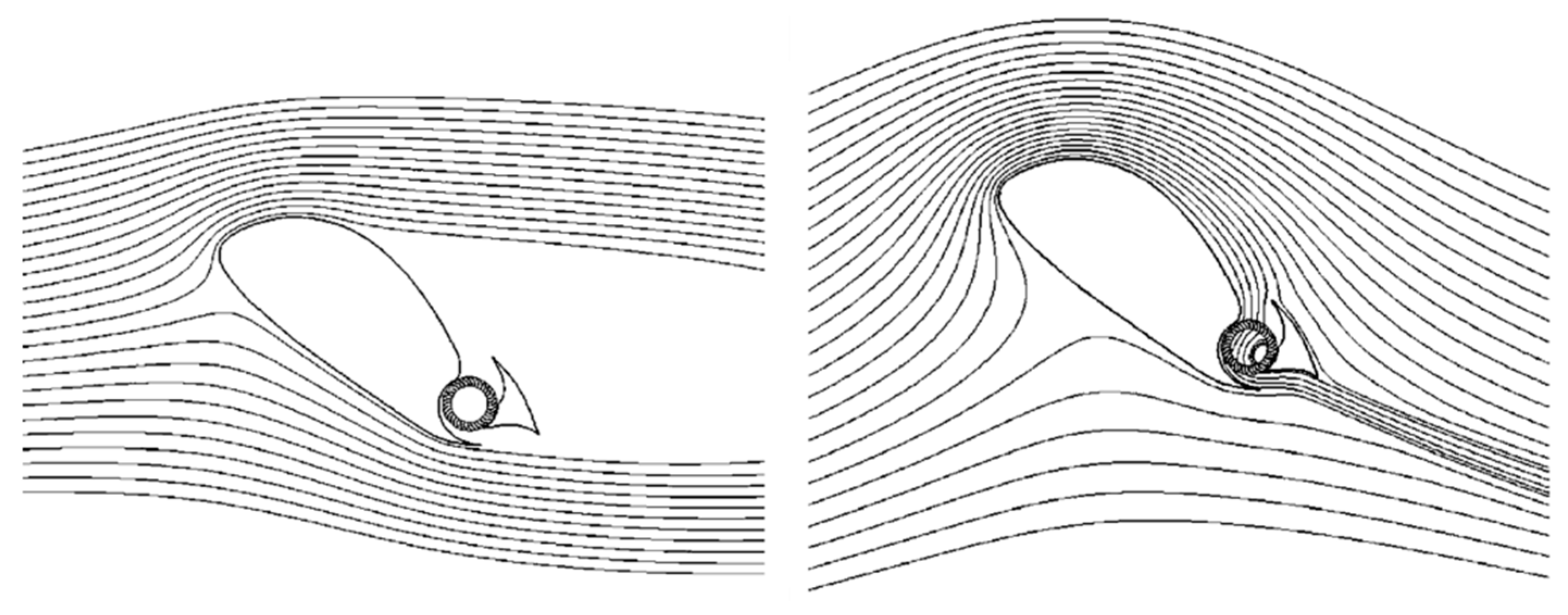
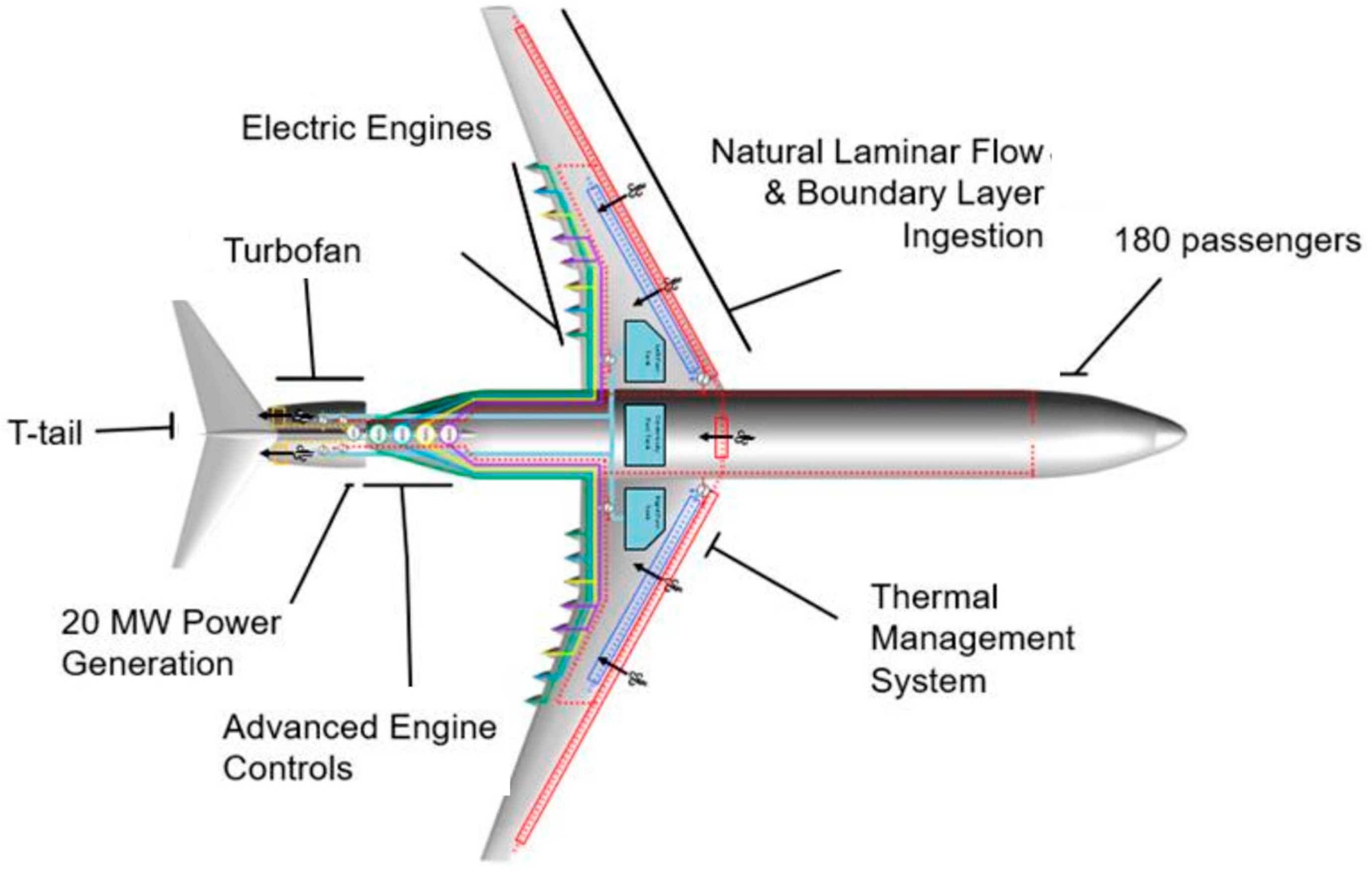
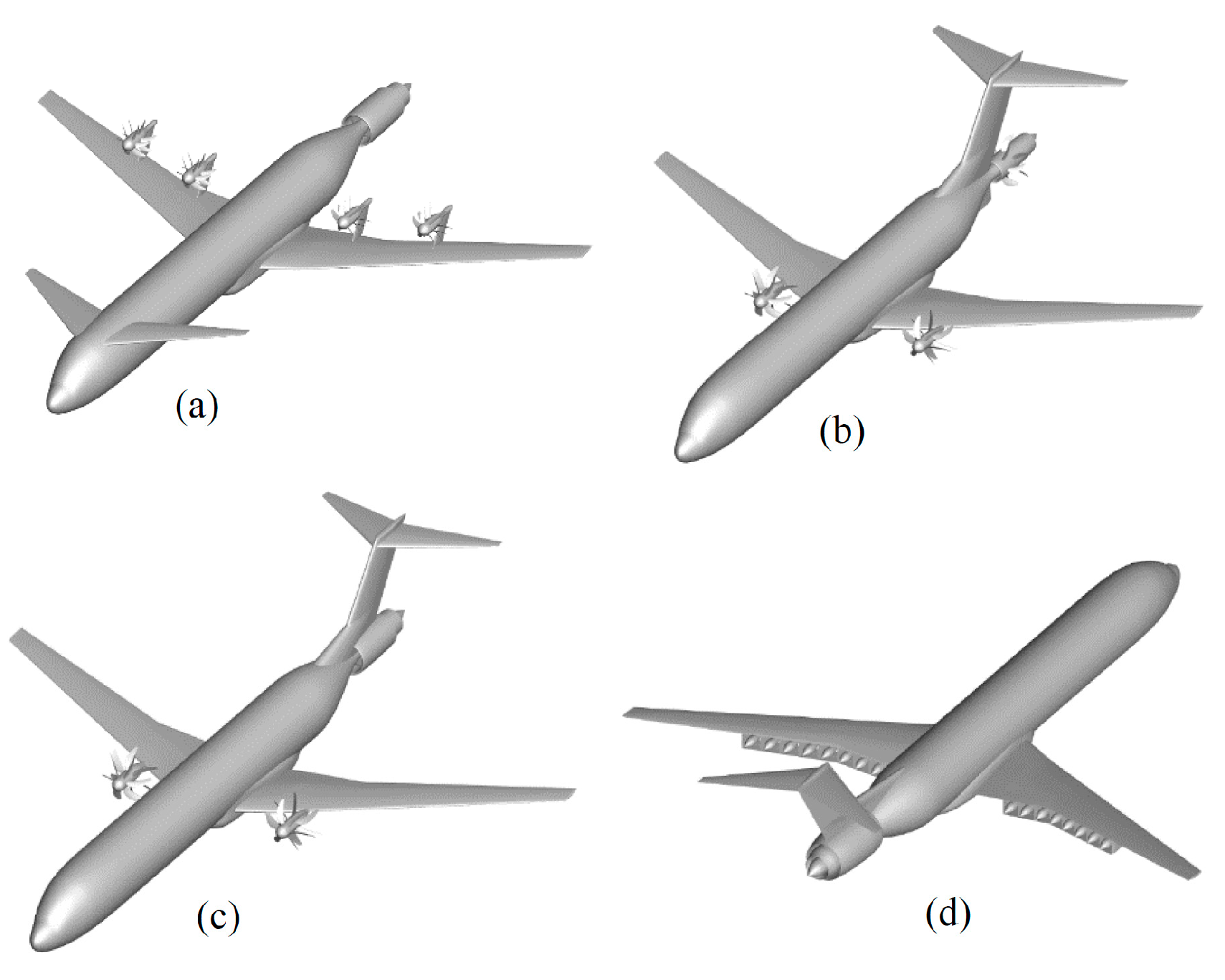
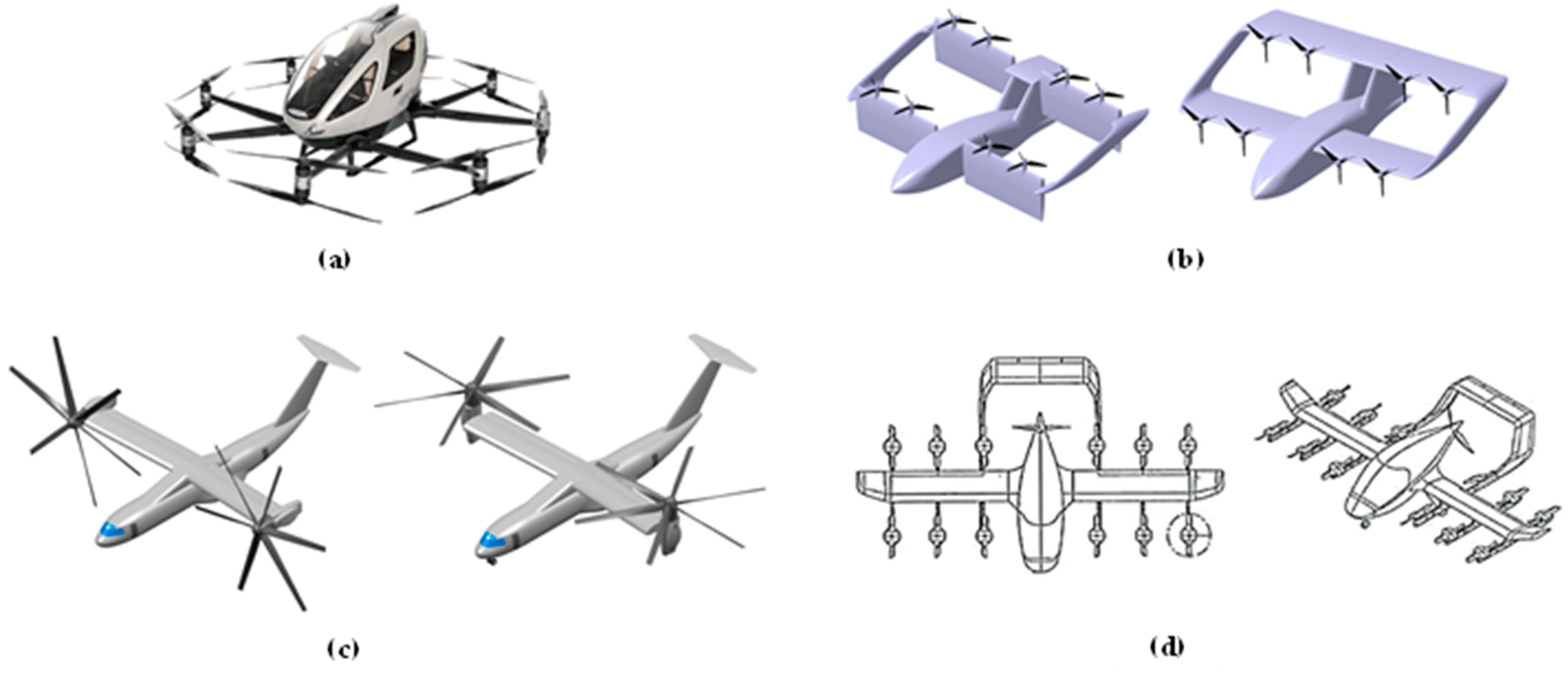
Table 1.
Mass breakdown of GOR and GTF. Data taken from ref. [116].
Table 1.
Mass breakdown of GOR and GTF. Data taken from ref. [116].
| GTF | GOR | |
|---|---|---|
| Engine core | 180 kg | 230 kg |
| Low pressure turbine and turbine exhaust frame | 420 kg | 510 kg |
| Gearbox | 215 kg | 505 kg |
| Propeller/fan including related structures | 770 kg | 1335 kg |
| Nacelle | 800 kg | 95 kg |
| Accessories, nozzles, bypass duct, bearings | 270 kg | 275 kg |
| Total mass | 2655 kg | 2950 kg |
Table 2.
Main data of the configuration studied in [163].
Table 2.
Main data of the configuration studied in [163].
| Main Data | |
|---|---|
| MTOW | |
| Wing surface | 34 m2 |
| AR | 13 |
| Length fuselage | 18 m |
| 1.9 | |
| Num. pax | 19 |
Table 3.
Main data of the optima configurations designed in ref. [173].
Table 3.
Main data of the optima configurations designed in ref. [173].
| 2 Props. Config. | 6 Props. Config. | 12 Props. Config. | |
|---|---|---|---|
| Transmission | geared | geared | geared |
| Propulsion weight [kgf] | 1634 | 1351 | 1335 |
| MTOW [kgf] | 24,700 | 23,950 | 23,890 |
| Wing area [m2] | 63.6 | 58.6 | 55.6 |
| Vertical tail area [m2] | 12.16 | 9.29 | 5.84 |
| AR | 14 | 14 | 14 |
| Wingspan [m] | 29.9 | 28.7 | 27.9 |
| 2.7 | 2.85 | 3 | |
| L/D | 17.4 | 17.3 | 17.5 |
| Block fuel [kg] | 2114 | 2078 | 2056 |
Table 4.
Main data of the optima configurations designed in ref. [175].
Table 4.
Main data of the optima configurations designed in ref. [175].
| Baseline | = 16 | = 32 | = 48 | |||||
|---|---|---|---|---|---|---|---|---|
| R [nm] | 600 | 900 | 600 | 900 | 600 | 900 | 600 | 900 |
| MTOW [×103 kgf] | 56.76 | 57.89 | 72.8 | 74.4 | 77.7 | 78.4 | 80.5 | 82.4 |
| Wing area [m2] | 116.21 | 116.47 | 104.26 | 106.71 | 119.89 | 121.26 | 118.26 | 124.12 |
| L/D | 18.47 | 18.46 | 18.05 | 18.03 | 17.81 | 17.82 | 17.49 | 17.47 |
| Block fuel [×103 kg] | 4.77 | 5.74 | 4.18 | 5.78 | 3.91 | 5.37 | 4.45 | 6.31 |
Table 5.
Main data of the optima configurations designed in ref. [176].
Table 5.
Main data of the optima configurations designed in ref. [176].
| Baseline | Serial | Turboelectric | |
|---|---|---|---|
| MTOW [×103 kgf] | 21.9 | 22.7 (+26.5%) | 22.4 (+2.3%) |
| OEW/MTOW | 43% | 42% | 42% |
| W/S [kgf/m2] | 367 | 562 (+53.1%) | 500 (+36.2%) |
| Wing area [m2] | 60 | 49 (−18.3%) | 44 (−26.7%) |
| L/D (cruise) | 17.5 | 18.4 (+5.1%) | 18.5 (+5.7%) |
| Block fuel [×103 kg] | 2.19 | 3.05 (+39.3%) | 2.24 (+2.3%) |
Table 6.
Comparison between the Tecnam P2006T and NASA X-57 [177].
Table 6.
Comparison between the Tecnam P2006T and NASA X-57 [177].
| P2006T | X-57 | |
|---|---|---|
| Wing area [m2] | 14.7 | 6.1 |
| AR | 8.8 | 15 |
| Wingspan [m] | 11.4 | 9.6 |
| Numb. of prop. | 2 | 14 (12 + 2) |
| MTOW [kgf] | 1230 | 1360 |
Disclaimer/Publisher’s Note: The statements, opinions and data contained in all publications are solely those of the individual author(s) and contributor(s) and not of MDPI and/or the editor(s). MDPI and/or the editor(s) disclaim responsibility for any injury to people or property resulting from any ideas, methods, instructions or products referred to in the content. |
© 2024 by the authors. Licensee MDPI, Basel, Switzerland. This article is an open access article distributed under the terms and conditions of the Creative Commons Attribution (CC BY) license (https://creativecommons.org/licenses/by/4.0/).
Share and Cite
MDPI and ACS Style
Abu Salem, K.; Palaia, G.; Bravo-Mosquera, P.D.; Quarta, A.A. A Review of Novel and Non-Conventional Propulsion Integrations for Next-Generation Aircraft. Designs 2024, 8, 20. https://doi.org/10.3390/designs8020020
AMA Style
Abu Salem K, Palaia G, Bravo-Mosquera PD, Quarta AA. A Review of Novel and Non-Conventional Propulsion Integrations for Next-Generation Aircraft. Designs. 2024; 8(2):20. https://doi.org/10.3390/designs8020020
Chicago/Turabian StyleAbu Salem, Karim, Giuseppe Palaia, Pedro D. Bravo-Mosquera, and Alessandro A. Quarta. 2024. "A Review of Novel and Non-Conventional Propulsion Integrations for Next-Generation Aircraft" Designs 8, no. 2: 20. https://doi.org/10.3390/designs8020020