Article

Finite Element Analysis of Patient-Specific Cranial Implants under Different Design Parameters for Material Selection

by
Manuel Mejía Rodríguez
1,
Octavio Andrés González-Estrada
2,* and
Diego Fernando Villegas-Bermúdez
2
1
School of Mechanical Engineering, Universidad del Valle, Cali 760042, Colombia
2
School of Mechanical Engineering, Universidad Industrial de Santander, Bucaramanga 680002, Colombia
*
Author to whom correspondence should be addressed.
Designs 2024, 8(2), 31; https://doi.org/10.3390/designs8020031
Submission received: 22 November 2023 / Revised: 15 February 2024 / Accepted: 22 February 2024 / Published: 27 March 2024

Abstract

:
This work presents the study of the thickness vs. stiffness relationship for different materials (PMMA and PEEK) in patient-specific cranial implants, as a criterion for the selection of biomaterials from a mechanical perspective. The geometry of the implant is constructed from the reconstruction of the cranial lesion using image segmentation obtained from computed axial tomography. Different design parameters such as thickness and perforations are considered to obtain displacement distributions under critical loading conditions using finite element analysis. The models consider quasi-static loads with linear elastic materials. The null hypothesis underlying this research asserts that both biomaterials exhibit the minimum mechanical characteristics necessary to withstand direct impact trauma at the implant center, effectively averting critical deformations higher than 2 mm. In this way, the use of PMMA cranioplasties is justified in most cases where a PEEK implant cannot be accessed.

1. Introduction

Globally, cranioencephalic trauma affects an estimated 200 individuals out of 10,000, with a higher prevalence among men in a ratio of 3:2, particularly within the age range of 20 to 30, possibly due to increased engagement in sports and high-risk activities [1]. Industrialized nations report falls from one’s own height as the leading cause (60% of cases), alongside traffic accidents and acts of violence, collectively contributing to a 3.4% mortality rate [2,3]. In Latin America, head trauma is predominantly linked to traffic accidents (motorcyclists and pedestrians) and violence (internal guerrilla conflicts) [4]. In Colombia, limited demographic studies focus on the incidence of mild or moderate traumatic brain injury, situations often requiring cranial implants. Research in Cali between 2003 and 2004 indicated that 52% and 30% of admitted traumatic brain injury cases were categorized as mild and moderate, respectively [5]. The mortality rate in Colombia for the period 2010–2017 was 10.7 per 100,000 inhabitants [6].
Biomechanics is a multidisciplinary field that plays a crucial role in addressing bone injuries and defects, particularly in the development of orthopedic implants. These implants, made from a variety of biomaterials, are essential for proper bone alignment and healing [7]. To enhance the interaction between these implants and bone tissue, bioinspired surface modifications are being explored, with the aim of creating next-generation implants [8]. The biomechanics of bone fractures and fixation, including the use of implants, is a key area of study in orthopedic trauma [9]. Orthopedic implant studies encompass design, new materials, and physiology [10,11]. To ensure the final product effectively restores the functionality of the missing biological structure, these disciplines must collaborate [12]. Engineering is vital in evaluating prototype designs, identifying flaws, refining implants, and assuring patients of improved quality of life.
For over 80 years, scientists have been investigating and evaluating various synthetic biomaterials to address cranial defects [12], and the exploration for new materials, including those with biodegradable features, continues [13]. Among them, we find PMMA, a polymethylmethacrylate ceramic mixed with a liquid monomer, which passes from a liquid system to a non-Newtonian one to end up solidifying, through an exothermic energetic release process, in the form desired by the orthopedist. PMMA is a durable, malleable, and relatively inexpensive biomaterial [14], very efficient in aesthetic terms for sealing asymmetric and extensive defects, with great properties for surgical use [15]. PMMA has demonstrated remarkable success rates exceeding 97% and boasts a notably low complication rate of less than 2.3% [16,17]. Inconveniences have also been reported due to the low porosity of PMMA implants, since it does not favor the cell growth of osteocytes, nor does it facilitate its vascularization, creating an inert material susceptible to infection, although the literature reports less than 5% of infections with this biomaterial [18]. Finally, low mechanical properties are attributed to it in terms of tensile strength (36 MPa), 4.7 times less than cortical bone (170 MPa) [19], which raises doubts in surgeons when assessing its mechanical strength and stiffness, especially considering that many of these patients may be at risk of experiencing significant impacts.
Currently, surgeons have put their interest in PEEK (Polyether Ether Ketone), a thermally stable biomaterial [20] with success rates exceeding 99% [21], as indicated by studies. This biomaterial boasts low post-surgical complication rates ranging from 0% to 9% [16,22], and infection-related complications are less than 6% [23,24]. Moreover, PEEK exhibits a tensile strength of 80 MPa, two times lower than cortical bone strength. These attributes position PEEK as a promising biomaterial for surgical applications, presenting a high success rate, low complication rates, and advantageous mechanical properties when compared to alternative materials like PMMA.
Both biomaterials exhibit comparable clinical success rates, low complication rates, low infection rates, and high aesthetic satisfaction reported by patients [22], making them seemingly suitable for shielding the brain from mechanical trauma. However, they diverge in mechanical properties and costs, with PMMA being approximately 55% more economical than PEEK (USD 2702 vs. USD 4684, approximate value for an implant in Colombia without osteosynthesis material). In [25], the authors proposed an integrative surgery management system for cranial reconstructions using patient-specific implants made of PMMA as an accessible and cost-effective solution for low-income countries. This cost differential underscores a significant economic consideration in choosing between the two materials for neurosurgical implants while maintaining comparable clinical effectiveness and patient satisfaction.
The digitization of medical implants and their subsequent analysis using computational mechanics, such as finite element (FE) analysis, has significantly advanced the exploration and investigation of implant design [26,27]. These tools allow engineers to evaluate various parameters, including thickness, geometrical features, thermal properties, materials, and applied boundary conditions. This enables the creation of more customized implants from a mechanical perspective, blending the most favorable attributes to ensure prolonged implant durability [28]. Computational modeling and simulation play a crucial role in the total product life cycle of implants, analyzing both surgical procedures and devices, taking into account the topics of both hard and soft tissue mechanics.
Research using FE analysis has been reported applied to cranial implants evaluating the variable thickness vs. type of material, where it has been concluded that the thickness factor is more relevant to stresses than the material used for its manufacture. However, the situation differs when it comes to deformation, and the elastic modulus of the material significantly affects the displacement field. In another set of experiments, researchers evaluated the stress–strain behavior of two types of cranial implants, titanium (Ti) and PEEK, under axial loading [29]. Special interest has been given to the geometric shape of the system of miniplates that hold the implant–skull interface and how these react to different types of loads [30,31]. In general, there has been a surge in research within the literature employing FE approaches to evaluate cranial implants [32,33,34,35], driven by a heightened interest in the subject. In [32], the authors employed finite element analysis to assess implant behavior under varied intracranial pressure conditions, considering the influence of fixation points, for different materials. The study in [33] models cranial implants with meshless methods, comparing solid and porous structures, for titanium alloy (Ti6Al4V) and PEEK, indicating titanium’s overall superiority, while PEEK excels in weight and osseointegration. In [35], evaluation of von Mises stresses and deformations in a customized PMMA-based cranial implant with the fixation system demonstrated effective protection without physiological harm or anchoring failures.
This work presents the study of the thickness vs. stiffness relationship for different materials (PMMA and PEEK), as a criterion for the selection of biomaterials from a mechanical perspective. Our null hypothesis is that the two biomaterials offer the minimum mechanical characteristics to withstand a direct impact trauma in the geometric center of the implant, e.g., as a result of a ball impact, and avoid critical deformations greater than 2 mm. In this way, the use of PMMA cranioplasties is justified in most cases where a PEEK implant cannot be accessed. First, the subject for the study is presented. Leveraging a computed tomography (CT) scan, we extract essential spatial and topological data, forming the foundation for precise model identification. Next, we continue with the design of a patient-specific implant, tailoring the solution to the individual’s unique anatomical characteristics. Finally, the structural integrity of the implant is assessed through finite element analysis, providing comprehensive insights into its performance under varying conditions, including material, topology, and thickness.

2. Materials and Methods

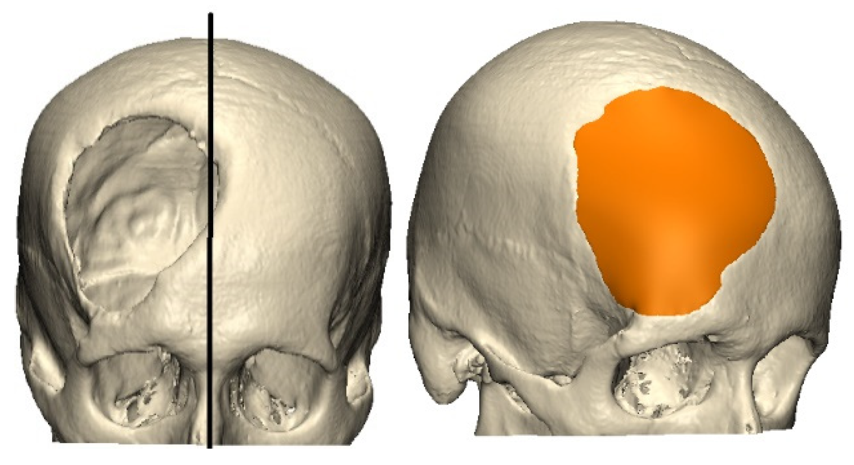
2.1. Model Identification

The subject of analysis in this study was the 3D reconstruction of a 32-year-old male patient’s cranium, originally from Ibagué, Colombia, who experienced a fracture and subsequent loss of bone tissue. The spatial and topological characteristics of the cranial defect were derived from a computed tomography (CT) scan of the cranial bones, as depicted in Figure 1. The relevant data were encoded in a DICOM (Digital Imaging and Communications in Medicine) extension file, with spatial slices at 0.625 mm and a gap of 0.625 mm between cuts, with a Gantry at 0°. The CT scan utilized a General Electric Dual HiSpeed scanner (General Electric, Chicago, IL, USA) with 250 slices, a pixel size of 0.124 mm, and implemented the B70s algorithm. This comprehensive imaging approach provided detailed insights into the structural alterations resulting from the injury.

2.2. Design of the Patient-Specific Implant (PSI)

For the personalized design of the implant based on the anatomy of the patient, a geometric and topological symmetry was assumed with respect to the sagittal axis, which was conveniently taken from the crista galli eminence and the anterior nasal spine of the patient [36]. Once this area was reflected on the defect, the thickness was calculated from the bone tables, and the customized implant was constructed using the CAD software Mimics v13 (Materialise, Leuven, Belgium). We have checked that the edges of the implant had a smooth continuity with the edges of the bone defect and were consistent with the anatomy of the patient. Figure 1 shows part of the defect and the patient-specific implant solution.

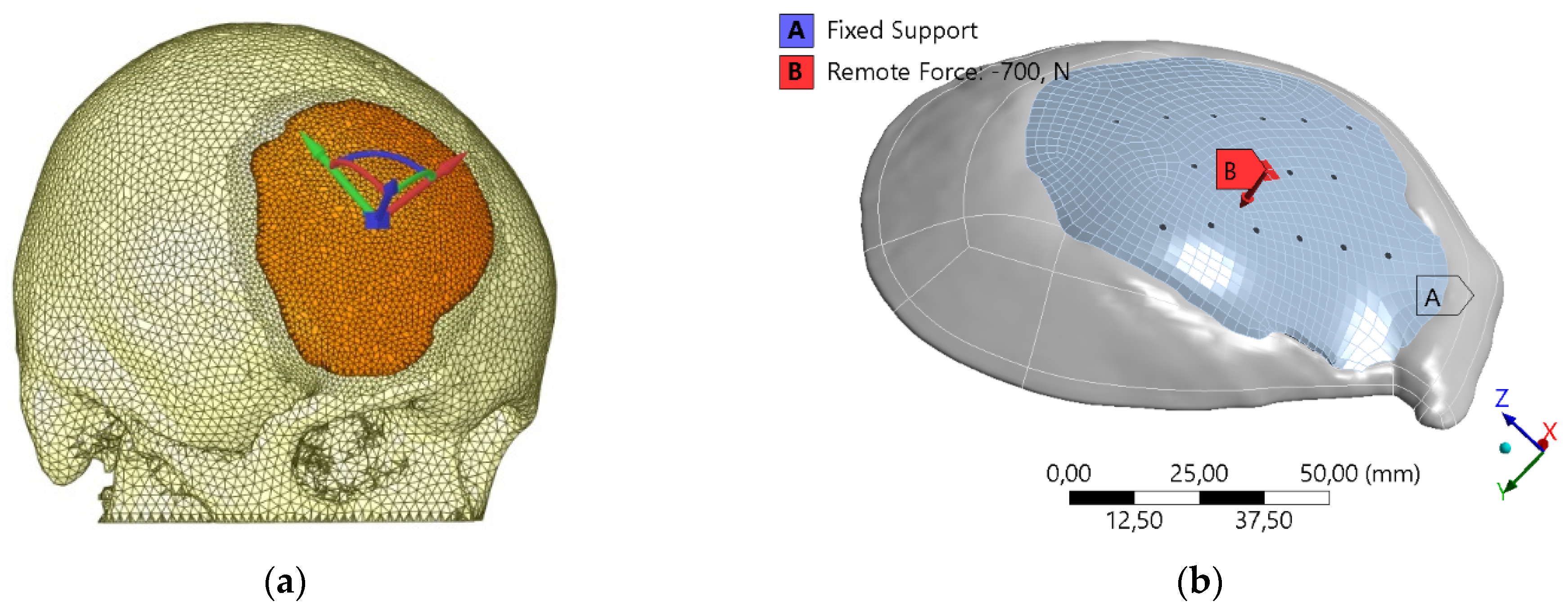
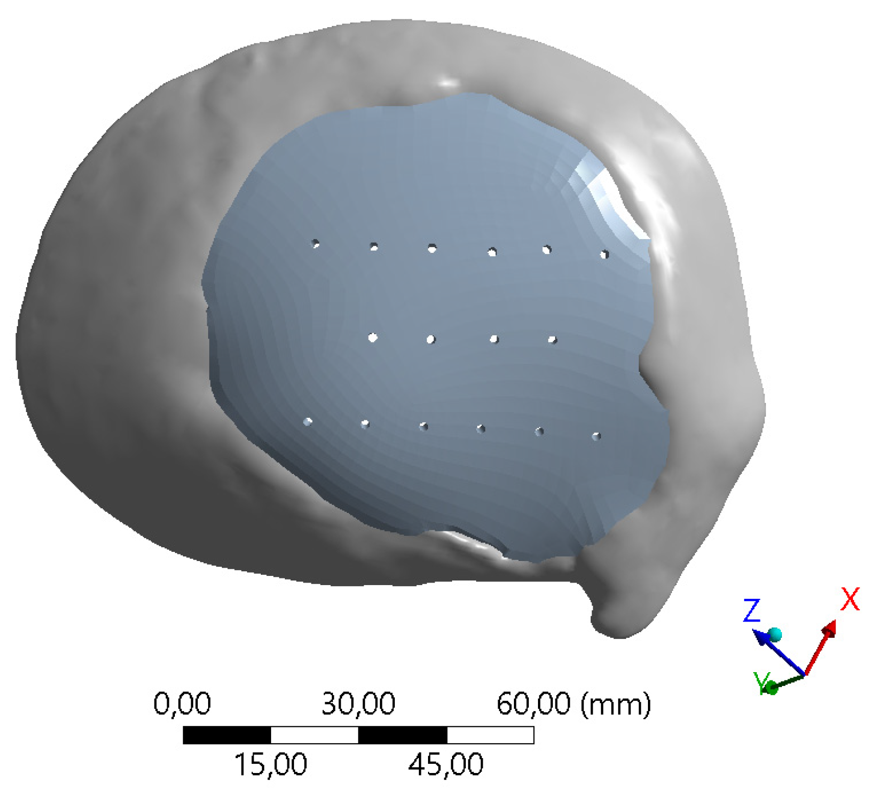
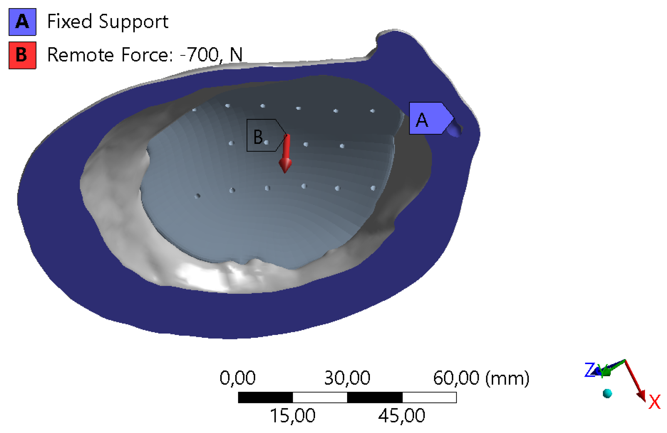
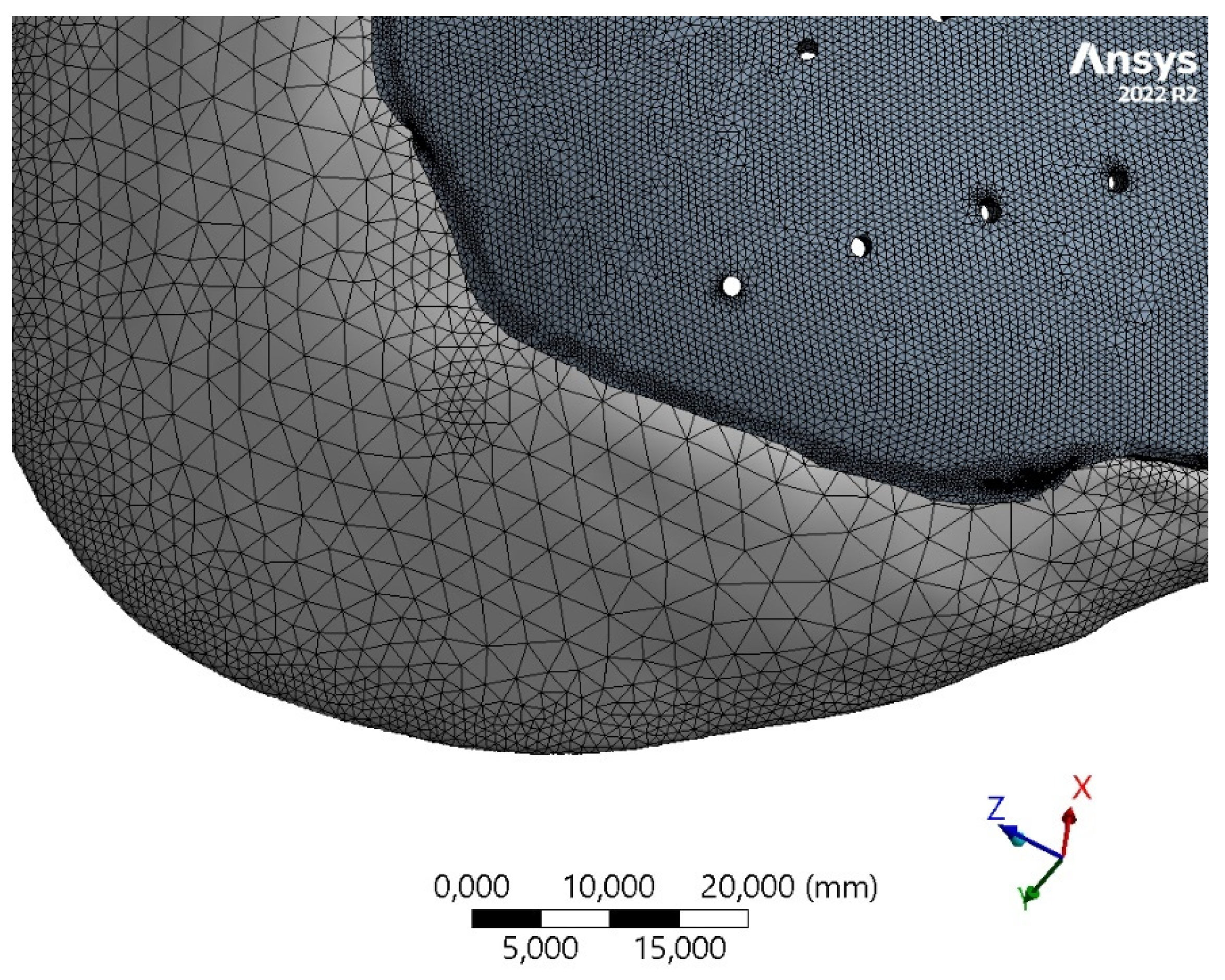
2.3. Finite Element Model
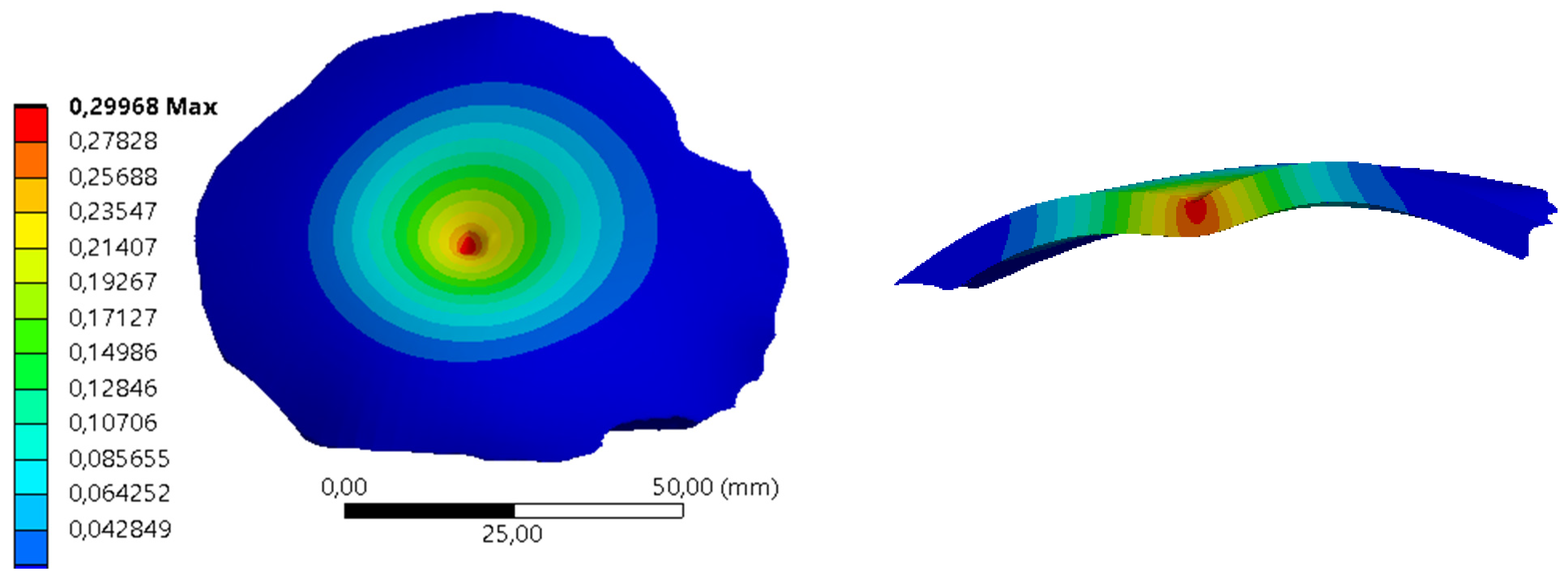
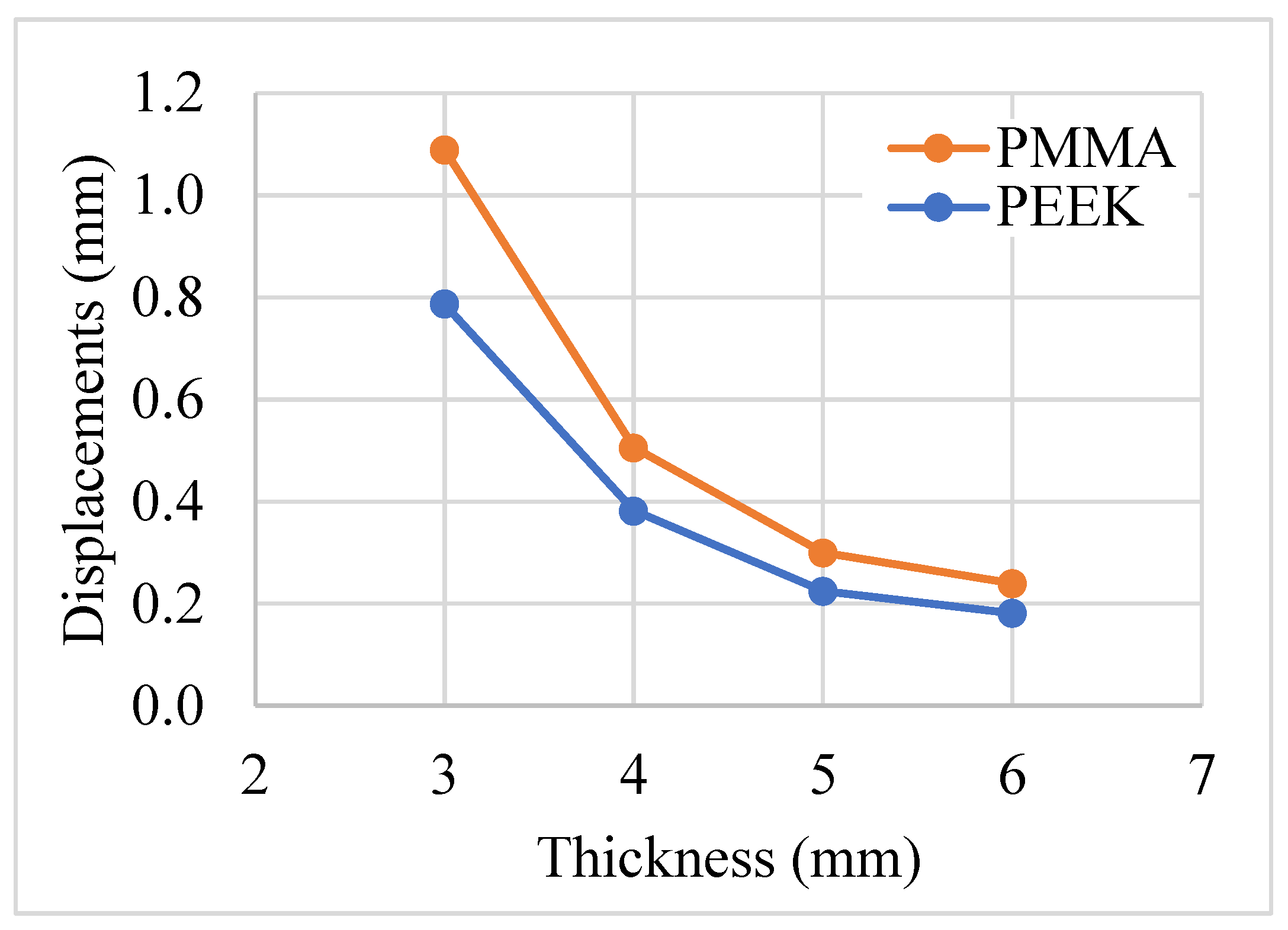
To evaluate the deformations of the implant under loading conditions, we use a standard Galerkin finite element numerical model to solve the elasticity problem. This method has been commonly used to evaluate the mechanical response in biomechanical applications [35,37,38]. Using a variational formulation of the elasticity problem and the finite element approximation of displacements, the following system of equations is obtained:
KU = f
where K is the stiffness matrix, U is the vector of nodal displacements and f is the load vector. Finite element analysis involves defining analysis type, boundary conditions, material model, and mesh generation. Post-processing evaluates results, followed by an analysis of their implications. To ensure the reliability and accuracy of the analysis, a mesh independence test is conducted, verifying the convergence of displacement solutions, considering that our quantity of interest is the total deformation. This iterative process ensures the robustness of the finite element method and the consistency of results, providing a comprehensive understanding of the studied phenomena.
For the problem under consideration, a linear static structural analysis with a direct solver is suitable to evaluate the behavior of the bone tissue, under the imposed boundary conditions. In a compression test, the bone tissue experiences loading that is applied slowly or at a constant rate, and the response of the material is observed under this quasi-static condition. For a linear analysis, the displacements are solved under the following assumptions: The stiffness matrix K is essentially constant, such that the materials have linear elastic behavior and small deformations theory is used. The load vector f is statically applied, i.e., no time-varying forces are considered, and no inertial effects are included.
The geometry of both the cranial implant (CI) and the skull base were exported in an IGES format, to generate a 3D model that is discretized to represent the geometric characteristics of the patient. The modeling software used was Ansys Workbench 2023 R1 (ANSYS Inc., Canonsburg, PA, USA). This FE tool allows an approximation of the differential equations that govern the stress–strain behavior of the elasticity problem, providing in a non-invasive way results that closely resemble real-world scenarios [39].
The research methodology focused on a  2 k  factorial design of experiments (DOE) with k factors corresponding to three key input variables of interest: (i) implant thickness, (ii) biomaterial, and (iii) uniformly distributed perforations. The choice of a 2k factorial design is motivated by its efficiency in exploring the effects of multiple factors simultaneously while requiring a relatively small number of experimental runs. This design allows for the systematic investigation of main effects and interaction effects, providing a comprehensive understanding of variable relationships. The statistical simplicity of analysis, resource savings, and the ability to efficiently screen factors make the 2k factorial design an advantageous choice. Table 1 provides details on the uncoded variables, where the design typically involves only two levels for each factor.
In a  2 k  factorial design of experiments with three factors, the effects represent the influence or impact of each factor and their interactions on the response variable. The general equation for calculating the main effects of each factor in a  2 k  factorial design is as follows:
E i = 1 2 k 1 j = 1 2 k 1 Y i 1 j = 1 2 k 1 Y i 2
where  E i  denotes the effect of the i-th factor,  Y i 1  and  Y i 2  are the average responses at the high and low levels of the i-th factor, respectively. Additionally, for interaction effects between two factors, the equation reads:
E i j = 1 2 k 2 j = 1 2 k 2 Y i 1 j 1 + Y i 2 j 2 j = 1 2 k 2 Y i 1 j 2 + Y i 2 j 1
where  E i j  represents the interaction effect between the i-th and j-th factors,  Y i 1 j 1  are the average responses at the high levels of the i-th and j-th factors,  Y i 2 j 2  are the average responses at the low levels of the i-th and j-th factors, and the remaining terms represent the coupled responses.
The properties of bone and alloplastic material were assumed and modeled under a continuous homogeneous isotropic approach, with a linear elastic model governed by the elastic modulus and Poisson’s ratio, which has shown a very good correlation for stress–strain analysis in human bones [40,41]. The mechanical properties of the linear elastic material models of the two biomaterials, PEEK and PMMA, are listed in Table 2, together with those of the cranial bone [42,43,44].
A load of 700 N was applied at the central apex of the implant as a remote force to avoid stress concentration effects, as previously used in [45], Figure 2. We did not consider the internal cranial hydrostatic pressure (15 mmHg) on the implant [45,46]. In the clinical procedure, patients are previously subjected to mechanical devices that regulate the intracranial pressure. Moreover, in [47], the authors measured the forces due to brain pulsation and indicated that they resulted in stresses one order of magnitude lower than the yield stress of the cranioplasty material. We measured the subarachnoid space in the CT scan for a maximum displacement of 2 mm, which is in agreement with values reported [48]. Cranial implants may incorporate holes or perforations to enable suturing for secure attachment to the skull, promote tissue integration and vascularization, facilitate drainage and fluid management, allow customization for individual patient needs, reduce weight for improved comfort, and provide diagnostic access or monitoring options when necessary. Thus, the implants were also drilled in a symmetrical pattern of 3 rows, with holes spaced at 1 cm and a diameter of 1.7 mm, as shown in Figure 3, since it was a factor to be evaluated.
A fixed boundary condition at the level of the flat edge of the cranial remnant was assumed, and the contact between the implant and the portion of the skull was defined as a non-separation condition, Figure 4. On the other hand, the center for the reference frame was located at the apex of the implant with a k-direction perpendicular to the surface at this point (Figure 2a). Convergence tests of the solution in displacements were performed to validate mesh independence using four meshes, with a final variation of 0.2% in the last mesh, as shown in Table 3, for a final element size of 1 mm, and a total of 1,521,702 elements. Skewness measure of the mesh was evaluated for element quality, with values below 0.95. Finally, meshes of second-order tetrahedral elements, considering the parameters in Table 4, were produced for the bone tissue and the implants, as shown in Figure 5.
Following this, the study assesses outcomes by modeling implants using both PEEK and PMMA biomaterials on cranial cortical bone. Under identical load conditions and constraints, the study aims to gauge the mechanical performance of both materials based on deformation parameters. This comparative analysis provides insights into how PEEK and PMMA perform in simulated conditions, aiding in the evaluation and selection of these biomaterials for cranial applications.

3. Results

In our study, a  2 3  factorial experiment was undertaken to examine the impacts of material type (PEEK and PMMA), implant thickness (3 mm and 5 mm), and the presence of perforations for suturing (with and without) on cranial implant performance. This design resulted in eight experimental runs, encompassing all possible combinations of these factors. The response variable, indicating the primary outcome (i.e., maximum displacement), was measured for each experimental run. Employing statistical analysis, we assessed the main effects and potential interactions among these factors, aiming to discern the influence of material choice, thickness variations, and the presence of perforations on the properties of cranial implants. The findings contribute valuable insights into optimizing cranial implant design based on these critical factors. The results of the eight experiments are presented in Table 5, which shows the maximum total displacements for different implant configurations.
Figure 6 and Figure 7 show the total displacements for the implants under a load of 700 N applied on the apex of the implant for two experiments of the different configurations of biomaterial, thickness, and perforations.
The effect that each one of the factors studied has on the normal displacements of the surface is presented in Table 6. The results of our study revealed several key findings regarding the main effects and interactions of factors on our experimental outcome. Regarding the main effects, implant thickness exhibited a notable negative effect with a coefficient of −0.684 (±0.01), indicating that increasing implant thickness was associated with a decrease in the observed outcome. Conversely, the choice of biomaterial showed a positive effect of 0.193 (±0.01), suggesting that certain biomaterials, i.e., PMMA, were associated with higher outcomes. Perforations, as a main effect, had a minimal effect with a coefficient of 0.022 (±0.01). In terms of two-factor interactions, the interaction between thickness and biomaterial showed a negative effect of −0.116 (±0.01), suggesting that the combination of certain thicknesses and biomaterials led to a reduction in the outcome. The interactions between thickness and perforations (−0.008 ± 0.01) and biomaterial and perforations (0.004 ± 0.01) had relatively minor effects on the observed outcome. These results provide insights into the complex interplay between implant characteristics and their impact on our experimental outcome.
The perforations or holes variable does not seem to have a noticeable influence on the deformations of the implant when the biomaterial is PMMA. Otherwise, when the biomaterial is PEEK, and the thickness is 3 mm, this combination seems to influence the displacements. In the configuration of change of thickness and biomaterial, it is observed that for thicknesses of 3 mm the biomaterial influences, but for thicknesses of 5 mm, it is not significant. The largest deformation was observed in the combination of 3 mm thickness, PMMA biomaterial, and holes with a displacement of 1.125 mm. In consideration of the influence of thickness, we have included data corresponding to thickness values of 4 mm and 6 mm. This addition is intended to facilitate a comprehensive understanding of the relationship between displacement and thickness increment. The influence of the thickness on the normal displacements to the surface in different combinations of biomaterials is presented in Figure 8. Comparing the displacement values between PMMA and PEEK implants at each thickness level, it appears that PEEK generally exhibits lower displacement values than PMMA, and the difference diminishes as we increase the thickness. The displacement decreases non-linearly with thickness for both materials, and when considering displacement as proportional to the elastic modulus, these findings align with the ratio of their respective elastic moduli. These findings can inform clinical decisions regarding the selection of implant materials and thicknesses based on desired mechanical performance and patient-specific factors such as bone quality and surgical requirements.

4. Conclusions

In this study, we investigated the relationship between implant thickness and deformation, focusing on patient-specific cranial implants constructed from two different biomaterials, PMMA and PEEK. Our goal was to assess their mechanical performance under quasi-static loads, particularly in terms of maximum total deformation. While the paper explores readily accessible techniques, its main objective is to address the cost-benefit aspects of employing PMMA implants in clinical applications, particularly in comparison to more expensive alternatives, an aspect that has not been previously explored in the literature. Our experience indicates that this matter lacks clarity for practitioners, and its relevance is notably significant in developing countries. Achieving a comprehensive grasp of the materials and their mechanical performance is relevant in this context. The outcomes of this research shed light on several crucial aspects of implant design and selection. As expected, the choice of biomaterial significantly impacts the deformation characteristics of cranial implants. We observed that PMMA and PEEK exhibit different levels of normal displacements due to their different elastic moduli. Generally, biomaterials with higher elastic moduli experience less deformation under equivalent stress conditions.
Our study adds a practical dimension to existing research [49] by considering implant perforations as an important factor in surgical procedures. Moreover, we did not consider implants thinner than 3 mm because the fabrication of these implants, generally by the biomaterial injection technique, are difficult to perform for clinical use. In comparison to previous literature, our findings diverge in terms of deformation outcomes. Díaz et al. [38] report displacements of 0.3 mm in PEEK biomaterial for a cranioplasty in the upper part of the cranial vault, although the implant thickness is not reported. Ridwan-Pramana et al. [50] report displacements less than 0.03 mm in specific configurations of several plates and positive contact angles between implant and skull; we understand that the other configurations are idealized and do not represent, in many cases, the real topological conditions of these defects in surgery. Finally, it is known that the perpendicular distance between the cranial tissue and the bone plate is around 2 mm [48,51]. For this reason, a deformation of the material close to this length would be critical. This deformation is closely linked to the thickness and material of the implant [49]. Thus, it is necessary for future research to include geometric variables, such as the radius of curvature of the implant. This will allow for a more precise standardization of results, catering to specific implant geometries and providing a more comprehensive understanding of implant performance. The finite element models employed in this study recreated real-life implant conditions under direct impacts, although the osteosynthesis system was not included.
This research validates the null hypothesis that both PMMA and PEEK biomaterials are suitable for withstanding deformation in the normal direction. Furthermore, we found that by adjusting the thickness variable in PMMA biomaterial, deformation levels comparable to those of PEEK can be achieved. These results suggest the potential for PMMA implants, particularly 4 mm thick with perforations, to serve as an effective alternative to PEEK implants, offering a cost-effective solution while maintaining the desired mechanical performance in cranial implants. However, further research and validation are essential to confirm the feasibility and clinical implications of these findings.
While the study enhances understanding of cranial implant performance, limitations exist. Focusing on quasi-static loads excludes dynamic conditions, and implants thinner than 3 mm were omitted. Idealized assumptions about perforations may oversimplify surgical scenarios. Future research should explore geometric variables, incorporate dynamic conditions, explore thinner implants, and integrate osteosynthesis systems for a more realistic analysis. Clinical validation is crucial to confirm practical implications. Despite these limitations, the study suggests the potential of cost-effective PMMA implants as comparable alternatives to PEEK implants, emphasizing the need for further research and validation in clinical settings.

Author Contributions

Conceptualization, M.M.R., O.A.G.-E. and D.F.V.-B.; Data curation, M.M.R.; Formal analysis, M.M.R., O.A.G.-E. and D.F.V.-B.; Investigation, M.M.R., O.A.G.-E. and D.F.V.-B.; Methodology, M.M.R., O.A.G.-E. and D.F.V.-B.; Supervision, O.A.G.-E.; Validation, M.M.R. and O.A.G.-E.; Writing—original draft, M.M.R.; Writing—review and editing, O.A.G.-E. and D.F.V.-B. All authors have read and agreed to the published version of the manuscript.

Funding

This work was supported by Universidad Industrial de Santander (grant numbers VIE-2522 and 3716). The authors have no competing interests to declare that are relevant to the content of this article.

Institutional Review Board Statement

The study was conducted according to the guidelines of the Declaration of Helsinki, and approved by the Ethics Committee of Industrial University of Santander (Act 18, 18 October 2019).

Data Availability Statement

Data will be made available on request.

Conflicts of Interest

The authors declare that they have no known competing financial interests or personal relationships that could have appeared to influence the work reported in this paper.

References

  1. Alted López, E.; Bermejo Aznárez, S.; Chico Fernández, M. Actualizaciones en el manejo del traumatismo craneoencefálico grave. Med. Intensiv. 2009, 33, 16–30. [Google Scholar] [CrossRef]
  2. Majdan, M.; Mauritz, W. Unintentional fall-related mortality in the elderly: Comparing patterns in two countries with different demographic structure. BMJ Open 2015, 5, e008672. [Google Scholar] [CrossRef]
  3. Faul, M.; Xu, L.; Wald, M.M.; Coronado, V.; Dellinger, A.M. Traumatic brain injury in the United States: National estimates of prevalence and incidence, 2002–2006. Inj. Prev. 2010, 16, A268. [Google Scholar] [CrossRef]
  4. Peñaherrera Oviedo, C.; Soria Viteri, J. Pregunta de investigación y estrategia PICOT. Medicina (B Aires) 2015, 19, 66. [Google Scholar] [CrossRef]
  5. Guzmán, F.; Moreno, M.C.; Montoya, A. Evolución de los pacientes con trauma craneoencefálico en el Hospital Universitario del Valle: Seguimiento a 12 meses. Colomb. Med. 2008, 39, 25–28. [Google Scholar] [CrossRef]
  6. Umaña Laiton, L.E. Características Sociodemográficas Relacionadas con la Mortalidad por Trauma Craneoencefálico en Adultos en Colombia. 2010–2017; Universidad del Rosario: Bogotá, Colombia, 2021. [Google Scholar]
  7. Kim, T.; See, C.W.; Li, X.; Zhu, D. Orthopedic implants and devices for bone fractures and defects: Past, present and perspective. Eng. Regen. 2020, 1, 6–18. [Google Scholar] [CrossRef]
  8. González-Estrada, O.A.; Pertuz Comas, A.D.; Ospina, R. Characterization of hydroxyapatite coatings produced by pulsed-laser deposition on additive manufacturing Ti6Al4V ELI. Thin Solid Films 2022, 763, 139592. [Google Scholar] [CrossRef]
  9. Altmann, M.; Cognet, J.-M.; Eschbach, L.; Gasser, B.; Richards, G.; Simon, P. Materiales utilizados en la osteosíntesis. EMC-Técnicas Quirúrgicas-Ortop. y Traumatol. 2009, 1, 1–8. [Google Scholar] [CrossRef]
  10. Bonda, D.J.; Manjila, S.; Selman, W.R.; Dean, D. The Recent Revolution in the Design and Manufacture of Cranial Implants. Neurosurgery 2015, 77, 814–824. [Google Scholar] [CrossRef] [PubMed]
  11. Corredor, E.; González-Estrada, O.A.; Ospina-Ospina, R. Deposición de láser pulsado de hidroxiapatita en Ti-6Al-4V producido por manufactura aditiva. Rev. UIS Ing. 2022, 21, 107–122. [Google Scholar] [CrossRef]
  12. Aydin, S.; Kucukyuruk, B.; Abuzayed, B.; Aydin, S.; Sanus, G.Z. Cranioplasty: Review of materials and techniques. J. Neurosci. Rural Pract. 2011, 2, 162–167. [Google Scholar] [CrossRef] [PubMed]
  13. Chmal-Fudali, E.; Basińska, D.; Kucharska-Jastrząbek, A.; Struszczyk, M.H.; Muzalewska, M.; Wyleżoł, M.; Wątrobiński, M.; Andrzejewski, J.; Tarzyńska, N.; Gzyra-Jagieła, K. Effect of the Advanced Cranial and Craniofacial Implant Fabrication on Their Degradation Affinity. Materials 2023, 16, 6070. [Google Scholar] [CrossRef] [PubMed]
  14. Caro-Osorio, E.; De la Garza-Ramos, R.; Martínez-Sánchez, S.; Olazarán-Salinas, F. Cranioplasty with polymethylmethacrylate prostheses fabricated by hand using original bone flaps: Technical note and surgical outcomes. Surg. Neurol. Int. 2013, 4, 136. [Google Scholar] [CrossRef] [PubMed]
  15. Webb, J.C.J.; Spencer, R.F. The role of polymethylmethacrylate bone cement in modern orthopaedic surgery. J. Bone Jt. Surg.-Ser. B 2007, 89, 851–857. [Google Scholar] [CrossRef] [PubMed]
  16. Liang, E.S.; Tipper, G.; Hunt, L.; Gan, P.Y.C. Cranioplasty outcomes and associated complications: A single-centre observational study. Br. J. Neurosurg. 2016, 30, 122–127. [Google Scholar] [CrossRef] [PubMed]
  17. Paredes, I.; Castaño-León, A.M.; Munarriz, P.M.; Martínez-Perez, R.; Cepeda, S.; Sanz, R.; Alén, J.F.; Lagares, A. Cranioplasty after decompressive craniectomy. A prospective series analyzing complications and clinical improvement. Neurocirugia 2015, 26, 115–125. [Google Scholar] [CrossRef]
  18. Huang, G.J.; Zhong, S.; Susarla, S.M.; Swanson, E.W.; Huang, J.; Gordon, C.R. Craniofacial reconstruction with poly(methyl methacrylate) customized cranial implants. J. Craniofac. Surg. 2015, 26, 64–70. [Google Scholar] [CrossRef]
  19. Cuppone, M.; Seedhom, B.B.; Berry, E.; Ostell, A.E. The Longitudinal Young’s Modulus of Cortical Bone in the Midshaft of Human Femur and its Correlation with CT Scanning Data. Calcif. Tissue Int. 2004, 74, 302–309. [Google Scholar]
  20. Fan, J.P.; Tsui, C.P.; Tang, C.Y.; Chow, C.L. Influence of interphase layer on the overall elasto-plastic behaviors of HA/PEEK biocomposite. Biomaterials 2004, 25, 5363–5373. [Google Scholar] [CrossRef]
  21. Iaccarino, C.; Viaroli, E.; Fricia, M.; Serchi, E.; Poli, T.; Servadei, F. Preliminary Results of a Prospective Study on Methods of Cranial Reconstruction. J. Oral Maxillofac. Surg. 2015, 73, 2375–2378. [Google Scholar] [CrossRef]
  22. Zhang, J.; Tian, W.; Chen, J.; Yu, J.; Zhang, J.; Chen, J. The application of polyetheretherketone (PEEK) implants in cranioplasty. Brain Res. Bull. 2019, 153, 143–149. [Google Scholar] [CrossRef]
  23. Alonso-Rodriguez, E.; Cebrián, J.L.; Nieto, M.J.; Del Castillo, J.L.; Hernández-Godoy, J.; Burgueño, M. Polyetheretherketone custom-made implants for craniofacial defects: Report of 14 cases and review of the literature. J. Cranio-Maxillofac. Surg. 2015, 43, 1232–1238. [Google Scholar] [CrossRef] [PubMed]
  24. Rosenthal, G.; Ng, I.; Moscovici, S.; Lee, K.K.; Lay, T.; Martin, C.; Manley, G.T. Polyetheretherketone implants for the repair of large cranial defects: A 3-center experience. Neurosurgery 2014, 75, 523–528. [Google Scholar] [CrossRef] [PubMed]
  25. Ulmeanu, M.-E.; Mateș, I.M.; Doicin, C.-V.; Mitrică, M.; Chirteș, V.A.; Ciobotaru, G.; Semenescu, A. Bespoke Implants for Cranial Reconstructions: Preoperative to Postoperative Surgery Management System. Bioengineering 2023, 10, 544. [Google Scholar] [CrossRef] [PubMed]
  26. Geng, J.P.; Ma, Q.S.; Xu, W.; Tan, K.B.C.C.; Liu, G.R.R. Finite element analysis of four thread-form configurations in a stepped screw implant. J. Oral Rehabil. 2004, 31, 233–239. [Google Scholar] [CrossRef]
  27. Morrison, T.M.; Dreher, M.L.; Nagaraja, S.; Angelone, L.M.; Kainz, W. The Role of Computational Modeling and Simulation in the Total Product Life Cycle of Peripheral Vascular Devices. J. Med. Device 2017, 11, 024503. [Google Scholar] [CrossRef]
  28. Moiduddin, K.; Mian, S.H.; Alkhalefah, H.; Ramalingam, S.; Sayeed, A. Customized Cost-Effective Cranioplasty for Large Asymmetrical Defects. Processes 2023, 11, 1760. [Google Scholar] [CrossRef]
  29. Lethaus, B.; Safi, Y.; Ter Laak-Poort, M.; Kloss-Brandstätter, A.; Banki, F.; Robbenmenke, C.; Steinseifer, U.; Kessler, P. Cranioplasty with customized titanium and PEEK implants in a mechanical stress model. J. Neurotrauma 2012, 29, 1077–1083. [Google Scholar] [CrossRef]
  30. Chamrad, J.; Marcián, P.; Narra, N.; Borák, L. Evaluating Different Shapes of Cranial Fixation Mini-plates Using Finite Element Method. In EMBEC & NBC 2017: Joint Conference of the European Medical and Biological Engineering Conference (EMBEC) and the Nordic-Baltic Conference on Biomedical Engineering and Medical Physics (NBC), Tampere, Finland, June 2017; Springer: Singapore, 2018; pp. 747–750. [Google Scholar]
  31. Santos, P.O.; Carmo, G.P.; Sousa, R.J.A.d.; Fernandes, F.A.O.; Ptak, M. Mechanical Strength Study of a Cranial Implant Using Computational Tools. Appl. Sci. 2022, 12, 878. [Google Scholar] [CrossRef]
  32. Bogu, V.P.; Ravi Kumar, Y.; Khanara, A.K. Modelling and structural analysis of skull/cranial implant: Beyond mid-line deformities. Acta Bioeng. Biomech. 2017, 19, 125–131. [Google Scholar] [CrossRef]
  33. Phanindra Bogu, V.; Ravi Kumar, Y.; Kumar Khanra, A. Homogenous scaffold-based cranial/skull implant modelling and structural analysis—Unit cell algorithm-meshless approach. Med. Biol. Eng. Comput. 2017, 55, 2053–2065. [Google Scholar] [CrossRef]
  34. Mian, S.H.; Moiduddin, K.; Elseufy, S.M.; Alkhalefah, H. Adaptive Mechanism for Designing a Personalized Cranial Implant and Its 3D Printing Using PEEK. Polymers 2022, 14, 1266. [Google Scholar] [CrossRef]
  35. Moncayo-Matute, F.P.; Torres-Jara, P.B.; Vázquez-Silva, E.; Peña-Tapia, P.G.; Moya-Loaiza, D.P.; Abad-Farfán, G. Finite element analysis of a customized implant in PMMA coupled with the cranial bone. J. Mech. Behav. Biomed. Mater. 2023, 146, 106046. [Google Scholar] [CrossRef]
  36. Winder, J.; McKnight, W.; Golz, T.; Giese, A.; Busch, L. Comparison of Custom Cranial Implant Source Data: Manual, Mirrored and CAD generated skull surfaces. In Medical Image Computing & Computer Assisted Intervention; Medical Image Computing and Computer Assisted Intervention Society: Copenhagen, Denmark, 2006. [Google Scholar]
  37. Maldonado, J.A.; Puentes, D.A.; Quintero, I.D.; González-Estrada, O.A.; Villegas, D.F. Image-Based Numerical Analysis for Isolated Type II SLAP Lesions in Shoulder Abduction and External Rotation. Diagnostics 2023, 13, 1819. [Google Scholar] [CrossRef]
  38. Díaz, J.M.; González-Estrada, O.A.; López, C.I. Biomechanical analysis of a cranial patient specific implant on the interface with the bone using the finite element method. In Proceedings of the VII Latin American Congress on Biomedical Engineering CLAIB 2016, Bucaramanga, Santander, Colombia, 26–28 October 2016; Springer: Berlin/Heidelberg, Germany, 2017; Volume 60, pp. 405–408. [Google Scholar]
  39. Tanaka, E.; Rodrigo, D.P.; Tanaka, M.; Kawaguchi, A.; Shibazaki, T.; Tanne, K. Stress analysis in the TMJ during jaw opening by use of a three-dimensional finite element model based on magnetic resonance images. Int. J. Oral Maxillofac. Surg. 2001, 30, 421–430. [Google Scholar] [CrossRef]
  40. Koolstra, J.H.; Van Eijden, T.M.G.J. Combined finite-element and rigid-body analysis of human jaw joint dynamics. J. Biomech. 2005, 38, 2431–2439. [Google Scholar] [CrossRef] [PubMed]
  41. Van Eijden, T.M.G.J.; Van Der Helm, P.N.; Van Ruijven, L.J.; Mulder, L. Structural and mechanical properties of mandibular condylar bone. J. Dent. Res. 2006, 85, 33–37. [Google Scholar] [CrossRef] [PubMed]
  42. Reilly, D.T.; Burstein, A.H. The elastic and ultimate properties of compact bone tissue. J. Biomech. 1975, 8, 393–405. [Google Scholar] [CrossRef] [PubMed]
  43. Chen, F.; Gatea, S.; Ou, H.; Lu, B.; Long, H. Fracture characteristics of PEEK at various stress triaxialities. J. Mech. Behav. Biomed. Mater. 2016, 64, 173–186. [Google Scholar] [CrossRef] [PubMed]
  44. Preusser, T.; Rumpf, M.; Sauter, S.; Schwen, L.O. 3D composite finite elements for elliptic boundary value problems with discontinuous coefficients. SIAM J. Sci. Comput. 2011, 33, 2115–2143. [Google Scholar] [CrossRef]
  45. Safi, Y.; Hohenberger, S.; Robbenmenke, C.; Banki, F.; Kessler, P.; Schmitz-rode, T.; Steinseifer, U. Investigation of the failure behavior of a cranial implant-skull model under different load conditions using FEM. SIMULIA Cust. Conf. 2010, 1, 16. [Google Scholar]
  46. Czosnyka, M.; Pickard, J.D. Monitoring and interpretation of intracranial pressure. J. Neurol. Neurosurg. Psychiatry 2004, 75, 813–821. [Google Scholar] [CrossRef] [PubMed]
  47. Goldberg, C.S.; Antonyshyn, O.; Midha, R.; Fialkov, J.A. Measuring Pulsatile Forces on the Human Cranium. J. Craniofac. Surg. 2005, 16, 134–139. [Google Scholar] [CrossRef] [PubMed]
  48. Saboori, P.; Sadegh, A. Histology and Morphology of the Brain Subarachnoid Trabeculae. Anat. Res. Int. 2015, 2015, 279814. [Google Scholar] [CrossRef]
  49. Marcián, P.; Narra, N.; Borák, L.; Chamrad, J.; Wolff, J. Biomechanical performance of cranial implants with different thicknesses and material properties: A finite element study. Comput. Biol. Med. 2019, 109, 43–52. [Google Scholar] [CrossRef]
  50. Ridwan-Pramana, A.; Marcián, P.; Borák, L.; Narra, N.; Forouzanfar, T.; Wolff, J. Structural and mechanical implications of PMMA implant shape and interface geometry in cranioplasty—A finite element study. J. Cranio-Maxillofac. Surg. 2016, 44, 34–44. [Google Scholar] [CrossRef]
  51. Martínez, F.; Mañana, G.; Panuncio, A.; Laza, S. Revisión anatomo-clínica de las meninges y espacios intracraneanos con especial referencia al hematoma subdural crónico. Rev. Mex. Neurocienc. 2008, 9, 47–60. [Google Scholar]
Figure 1. Midline used to reflect the right zone in the left zone (cranial defect).
Designs 08 00031 g001
Figure 2. (a) Reference frame with k-direction perpendicular to the skull surface, (b) force vector perpendicular to the implant.
Designs 08 00031 g002
Figure 3. Drilled implant at the apex level.
Designs 08 00031 g003
Figure 4. Boundary conditions. Load condition of 700 N on the implant apex in red, restriction of all degrees of freedom on the flat area of the cranial edge in blue.
Designs 08 00031 g004
Figure 5. Meshing of the implant and bone solids.
Designs 08 00031 g005
Figure 6. Total displacements (mm) of the 5 mm thickness PEEK implant.
Designs 08 00031 g006
Figure 7. Total displacements (mm) of the 5 mm thickness PEEK implant with perforations.
Designs 08 00031 g007
Figure 8. Effect of thickness on normal displacements for PEEK and PMMA for the implant without perforations.
Designs 08 00031 g008
Table 1. Input variables for the factorial design of the experiment.
FactorsCoded Level
−1+1
Implant thickness (A)3 mm5 mm
Biomaterial (B)PEEK PMMA
Perforations (C)NoYes
Source. Own elaboration.
Table 2. Mechanical properties of the biomaterial PEEK, PMMA, and cranial bone.
MaterialElastic Modulus (MPa)Poisson’s Ratio
PEEK40000.38
PMMA30000.38
Cranial bone15,0000.3
Source. Own elaboration.
Table 3. Mesh independence test for total normal displacement.
Number of ElementsMax. Total Displacement (mm)
224,3020.28775632
399,4750.29616231
761,2020.29734957
1,521,7020.29806294
Source. Own elaboration.
Table 4. Mesh parameters for the implant and bone solids.
ParameterImplantBone
Edge length (mm)11
Minimum edge length (mm)0.51
Smooth transitionYesYes
Bend angle7.5°
Number of elements576,596749,866
TetrahedraYesYes
Source. Own elaboration.
Table 5. Average results of the  2 3  factorial experiment.
ExperimentABCOutlet (mm)
ξ
10.787
2+0.811
3+1.089
4++1.125
5+0.225
6++0.237
7++0.300
8+++0.316
Source. Own elaboration.
Table 6. Calculated effects and standard errors for the factorial design.
Main EffectsEffectStandard Error
Thickness−0.684±0.01
Biomaterial0.193±0.01
Perforations0.022±0.01
Two-factor interactions
Thickness × Biomaterial−0.116±0.01
Thickness × Perforations−0.008±0.01
Biomaterial × Perforations0.004±0.01
Source. Own elaboration.
Disclaimer/Publisher’s Note: The statements, opinions and data contained in all publications are solely those of the individual author(s) and contributor(s) and not of MDPI and/or the editor(s). MDPI and/or the editor(s) disclaim responsibility for any injury to people or property resulting from any ideas, methods, instructions or products referred to in the content.

