

Investigation on the Microstructure and Micro-Mechanical Properties of Thermal-Sprayed NiCoCrAlY High Entropy Alloy Coating


1
Adelaide Microscopy, The University of Adelaide, Adelaide, SA 5005, Australia
2
Chitkara Centre for Research and Development, Chitkara University, Baddi 174103, Himachal Pradesh, India
3
Department of Mechanical Engineering, Amrita School of Engineering, Amrita Vishwa Vidyapeetham, Coimbatore 641112, Tamil Nadu, India
4
Centre for Research Impact & Outcome, Chitkara University, Rajpura 140401, Punjab, India
5
School of Civil and Mechanical Engineering, Curtin University, Bentley, WA 6102, Australia
*
Author to whom correspondence should be addressed.
Designs 2024, 8(2), 37; https://doi.org/10.3390/designs8020037
Submission received: 24 March 2024
/
Revised: 15 April 2024
/
Accepted: 19 April 2024
/
Published: 20 April 2024
(This article belongs to the Special Issue Additive Manufacturing, Structural Materials Design and Mechanical Engineering)
Abstract
:NiCoCrAlY high entropy alloy (HEA) coating (47.1 wt.% Ni, 23 wt.% Co, 17 wt.% Cr, 12.5 wt.% Al, and 0.4 wt.% Y) was deposited on a stainless steel subtract by atmospheric plasma spraying (APS). The as-deposited coating was about 300 μm thickness with <1% porosity. The microstructure of the coating consisted of dispersed secondary phases/intermetallics in the solid solution. The stress–strain behaviour of this coating was investigated in micro-scale with the help of in situ micro-pillar compression. The experimental results show that yield and compressive stress in the cross-section of the coating was higher (1.27 ± 0.10 MPa and 2.19 ± 0.10 GPa, respectively) than that of the planar direction (0.85 ± 0.09 MPa and 1.20 ± 0.08 GPa, respectively). The various secondary/intermetallic phases (γ′–Ni3Al, β–NiAl) that were present in the coating microstructure hinder the lattice movement during compression, according to Orowan mechanism. In addition to that, the direction of the loading to that of the orientation of the phase/splat boundaries dictate the crack propagation architecture, which results in difference in the micro-mechanical properties.
1. Introduction
Thermal barrier coatings (TBCs) are an integral part of the components that operate at a high temperature, and ensures the effective lifetime of the components. The main role of the TBCs is to protect the substrate from high heat exposure and find applications in gas turbines, aeronautical machineries, and power generation equipment [1,2,3]. In addition to protecting the substrate, TBCs also act as a barrier towards high-temperature oxidation and corrosion resistance. The utmost importance of selecting the elements of TBCs is the similar thermal expansion coefficient. Upon experiencing numerous thermal cycles, the coatings eventually fail mechanically as a result of the generated stress between the coating and subtract [4]. To minimise this, TBCs are composed of three distinct layers on the substrate. The first layer is usually an yttria-stabilised ceramic coating, usually know as ‘top coat’ in the literature. This layer has low thermal conductivity and allows the growth of aluminium oxide in service and thus, provides an effective barrier against high temperature [5]. The following layer is a ‘thermal growth oxide (TGO) layer’, and they find their place between the ‘top coat’ and ‘bond coat’, and form via a diffusional process, to that of the elements from the bond coat [6,7,8]. The third layer is the ‘bond coat’. The ‘bond coat’ in the TBCs serve two functions: (i) to avoid oxidation of the metallic substrate and (ii) to relieve the stress that is generated from the ‘thermal expansion’ mismatch between the substrate and ‘top coat’ (oxidation layer) [9].
Towards the development of the ‘bond coat’, a non-equimolar MCrAlY (M = Ni and/or Co) high entropy alloy (HEA) coating is promising, as stated in the literature [10]. Each of the elements in such alloy serves a specific purpose. For example, the Cr in the alloy provides resistance against high temperature corrosion. The presence of a minute amount of Y ensures solid solution hardening, in addition to improvement of the adhesion among alloy constituents. The presence of Co ensures blocking the movement of the lattice upon external loading through resistance against dislocation movements and grain boundary movements, and thus enhances the resistance against mechanical loading and creep [11]. The presence of 8–15 wt.% Al in the alloy hinders the crystal growth, which results in a stable aluminium oxide layer (α-Al2O3) upon high temperature exposure [12,13]. The increase in Al content in the alloy facilitates the formation of the β-(Ni,Co)Al phase and continuous α-Al2O3 in the MCrAlY type coatings [14]. The presence of Y in the alloy plays a secondary role by enhancing the adhesion of the alumina oxide with rest of the alloy constituents [13,15]. This improved adhesion enhances the ‘cyclic oxidation resistance’ of the coating [16], thanks to the presence of the reactive Y in the HEA. This also enables the use of the HEA coating in high temperature electrical insulators and sensors [17]. Traditionally, the HEAs are formed via casting into bulk form, which forms different detrimental oxide phases in the alloy. This can be avoided when the HEAs are deposited in the form of coating by ‘vacuum plasma spraying’ (VPS) [18,19], ‘atmospheric plasma spraying’ (APS) [20], or ‘high-velocity oxygen fuel’ (HVOF) spraying [21,22,23]. Among them, APS process is simple in operation and less expensive. The careful selection of spraying parameters can produce high-quality denser coating [24]. Most of the reported work on MCrAlY bond coat in the literature [16,17,18] focused on the temperature-dependent oxidation [25,26] and corrosion aspect [27,28] of the coating with few reports on the tribological behaviour [4,29]. However, there are no reports available on the micro-mechanical behaviours of such coatings.
As mentioned before, when exposed to the operating environment, such coating is impinged by the air, salts, debris, particles, etc., that may penetrate the porous top coat [27]. Thus, beside the investigations in regards to the oxidation and corrosion behaviours of such coating system, their micro-mechanical properties exploration is foreseen. Given the limited profile of the coatings, it is not possible to conduct traditional tensile tests on such materials deposited as coatings. This can be overcome by conducting in situ micro-pillar compression to determine the stress–strain curves under compression. This technique has been proven successful to determine the micro-mechanical properties of both bulk [30,31] and coating [32], as reported in the literature. Thus, the novelty of the present work to is investigate the stress–strain behaviour of NiCoCrAlY coating deposited by thermal spraying with the help of in situ micropillar compression, which has never been addressed before. In this research, along with the micro-mechanical properties, the structural deformation of nickel-based NiCoCrAlY HEA coating deposited on stainless steel 316 substrate was also investigated.
Thus, the aim of the present research is to explore the micro-mechanical properties of the APS-deposited NiCoCrAlY coating on stainless substrate. To achieve that, in situ compression on the micro-pillars were carried out. The associated deformation mechanisms were investigated by examining the deformed micro-pillars with an electron microscope.
2. Experimental Section
2.1. Deposition and Characterization of the Coating
In order to deposit the coating, the pre-alloyed powder of NiCoCrAlY was commercially acquired from Sulzer Metco, Winterthur, Switzerland. This specific powder composition is commercially known as Amdry 365-2. It is a Ni-rich alloy with the following composition: 47.1 wt.% Ni, 23 wt.% Co, 17 wt.% Cr, 12.5 wt.% Al, and 0.4 wt.% Y. The powder was prepared by a gas atomisation process [33] and the powder morphology is spherical, with a mean diameter of 5–38 μm as stated by the supplier [34]. Before coating deposition, the substrate was blasted by quartz sand (80–120 µm grit size), to ensure the proper adhesion of the coating with the substrate. The blasted surface was cleaned by sonication to remove any dirt/grease. The spraying gun was Diamond Jet 2700 plasma sprayer (Sulzer Metco, Switzerland), equipped with IRB 2400/16 automatic controller (ABB, Zurich, Switzerland). The optimal spraying parameters are as follows: 0.7 m3/h hydrogen flow rate, 0.7 m3/h argon flow rate, 40–50 g/min powder feed rate, 800 mm/s gun speed, 3 mm inter-pass spacing, 12 cm spraying distance, 38–40 bar of pressure, and with stand-off distance of 20–60 mm, and the substrate temperature was <150 °C. These parameters were selected based on the information available in the literature [4,7,13,28,29], as well as on the ‘trial and error’ approach to fine tune the parameters, as required by the currently employed deposition instrument.
After coating deposition, the specimen was sectioned with a water-cooled diamond saw to cut into pieces to carry out hot resin mounting and metallographic polishing. The polishing was conducted in Struers automatic polishing machine with a varying degree of diamond slurry with final polishing with colloidal silica suspension. The specimen was prepared in both planar and cross-sectional direction, and the microstructure was investigated by a field emission scanning electron microscope (Quanta 450 FE-SEM, Thermofisher Scientific, Waltham, MA, USA) and Oxford energy dispersive X-ray (EDX) analysis system (Oxford Instruments, Oxford, UK). Transmission electron microscopy (TEM) was carried out with a probe-corrected Titan TEM (Thermofisher Scientific, USA) at 200 KV. Both the micro-pillars and TEM samples were prepared by a focused ion beam (FIB)-SEM (Helios Nanolab 600, Thermofisher Scientific, USA). X-ray diffractometer (XRD) with monochromatic CuKα radiation (New D8 advance, Bruker, Karlsruhe, Germany) was used to investigate the phases in the coating.
2.2. Micro-Pillar Fabrication and Stress–Strain Calculation
Details of the micro-pillars fabrication and in situ micro-pillar compression was as follows: A focused ion beam (FIB-SEM) system (Helios Nanolab 600, FEI) was used to fabricate micro-pillars with Ø 3 µm. The micro-pillars were fabricated at the middle of 30 µm pit to avoid any contact of the indenter with the surrounding rim of the pit. Rough milling was carried out at 6.5 nA current at 30 kV, with final milling at 0.46 nA at 30 kV. A flat diamond punch of Ø 5 µm mounted on in situ nanoindentation system (PI 88, Hysitron) was used to conduct the compression tests. During compression, a 3 nm/s loading rate was selected, which corresponds to a 10−3 s−1 strain rate. The unloading rate was 50 nm/s. The whole process was recorded via videos. Deformed micro-pillars were also investigated by SEM.
Applied normal force (F) and the corresponding change in pillar length (Δl) was recorded during compression by a computer-controlled program, and subsequently used to calculate engineering stress and strain according to Equations (1) and (2):
where σ is engineering stress, F is normal force, and A0 is cross-sectional area of the pillar at 25% of its height from top. As the pillars were slightly taper (<2°), thus, most probable deformation will happen closer to the top surface [32].
where εE is engineering strain, Δl is change in pillar length, and l0 is initial pillar length. The details of the equations can be found in the literature [35,36]. A number of micro-pillars were fabricated on both planar and cross-section direction of the coatings. To ensure reproducibility, at least five individual experiments were conducted in each direction and representative curves were presented in the paper.
3. Results and Discussion
3.1. Coating Characterization
During the thermal spraying process, the as-received NiCoCrAlY powders experienced high temperature exposure for a fraction of a second, became molten/semi-molten, and thrust towards the substrate. The high velocity impact caused the molten/semi-molten droplets to flatten and anchor on the substrate surface. Due to this, the as-deposited coating surface is rough [37]. Thus, to unravel the microstructure on both the planar and cross-section direction, the coating was subjected to a metallographic polishing, as stated in the Experimental Section. A typical cross-sectional and planar view SEM micrograph is shown in Figure 1. The cross-sectional image of the coating (Figure 1a) shows a laminar microstructure, with a stack of splashes, which are unique of the thermal spraying-deposited material [38]. The total coating thickness was about 300 μm. However, the top section of the coating (with resin interface) is flaky in nature, which may result due to the applied force during coating deposition/hot mounting process. Withstanding that, the bottom section of the coating (with substrate interface) was dense, with an average thickness of around 145 μm. As can be seen from coating/substrate interface, the coating was well bonded with the grit-blasted substrate. In addition to that, a well-defined interface of coating/substrate was observed without significant oxide region. The planar view of the coating (Figure 2b) shows uniform microstructure composed of numerous individual splats. There were also few pores that formed on the coatings due to the trapped hot air during plasma spraying, which was below 1%, as calculated by image analysis. Some polishing debris were attached to the surface even after ultrasonic cleaning.
As can be seen from Figure 1, the microstructure of the coating is complex, and resulted due to the thermal spraying process. The different elements of the coating composition own different wettability, density, and melting points, and thus, experience different amounts of heat. During thermal spraying, the feed-stock powder became molten/semi-molten due to residing in the flame, even for a fraction of a second. Thus, the homogeneous distribution of the constituent elements took place in the deposited coating, and resulted in a complex microstructure. Higher magnification secondary (SE) and back-scattered (BSE) images on the cross-section of the coating are shown in Figure 2a,b, respectively. It is evident from Figure 2 that, the multiphase NiCoCrAlY coating microstructure is made of two main phases: (i) a gamma (γ-Ni) phase matrix made of Cr and Co solid solution, and (ii) a disperse beta phase (β-NiAl) [6,32,37]. The specimen mainly consists of primary β–NiAl (BCC, gray), with a fine α–Cr (black) precipitates, β–NiAl/α–Cr eutectic, and γ–Ni (FCC, white) distributing along eutectic boundaries. The existence of such phases were confirmed by the EDX point analysis, as show in Figure 3. Moreover, it was further supported by the XRD analysis, as reported later in the section. Cuboidal Ni3Al (γ′) of several hundred nano-meters were also located along a certain orientation direction from the γ-matrix.
The elemental mapping on the cross-section of the coating is shown in Figure 4 along with the EDS spectra. Figure 4a shows the layered (overlayer) EDS images, with individual elemental images on Figure 4b–f, together with the EDS spectra in Figure 4g. As stated in the previous section, based on SEM micrograph interpretation, the coating is mainly composed of a solid solution of Ni, with a number of other phases/intermetallics in it. A peak of oxygen was identified from the EDS spectra (Figure 4g), which resulted from the oxidation of the elements, in the course of the thermal spraying. Due to that, various forms of oxides formed in the coating, which is unavoidable [3]. Among the different coating constituents, Al is prone to oxidation due to its high affinity towards oxygen to form oxides. Therefore, the amount of Al, detected by the EDS, is in the lower range of the content. In contrast to the microstructure of the bulk alloy of similar composition, the extent of secondary phase/precipitation is much restricted in the coating. This prevailed due to the rapid solidification, where time-dependent phase/precipitation was limited [39,40,41,42,43]. It is worthy to note that the Y content was below the detection limit of the instrument, and thus, was not quantifiable.
Similar to that, the elemental mapping on the planar view of the coating is shown in Figure 5, with the associated EDS layered map (Figure 5a), individual elemental distribution (Figure 5b–f), and EDS spectra (Figure 5g). Similar to that appearance on the cross-section, the planar view also confirmed the presence of a solid solution, together with the splat boundaries and heterogeneous distribution of the different phases.
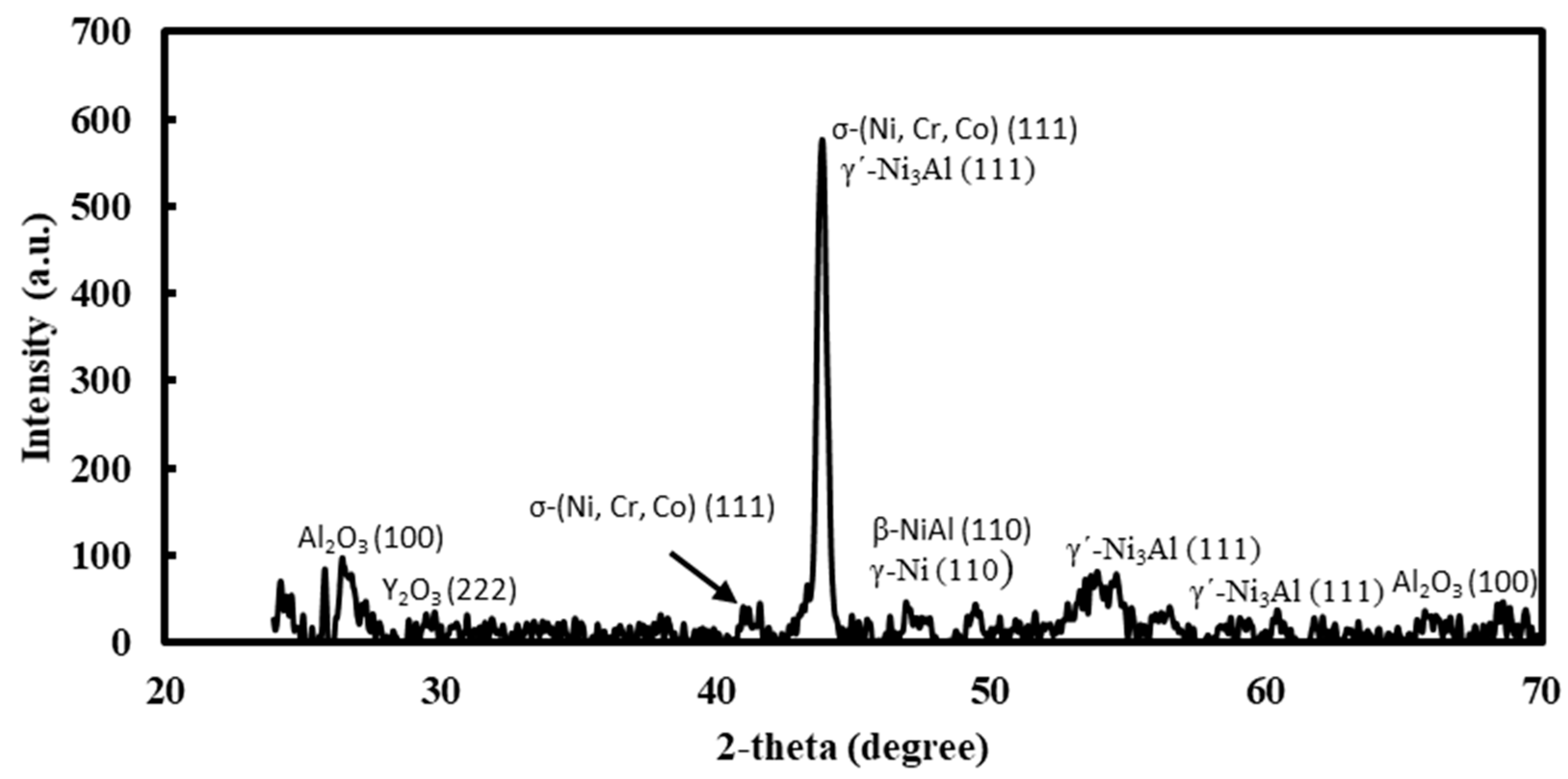
The XRD spectra that was obtained on the coating is shown in Figure 6. The XRD spectra confirms the existence of the different phases, which were identified by the EDS analysis. The main phases of the coating were σ-(Ni, Co, Cr), γ-Ni/γ′-Ni3Al, β-NiAl, and various oxides (mainly Al2O3 and Y2O3).
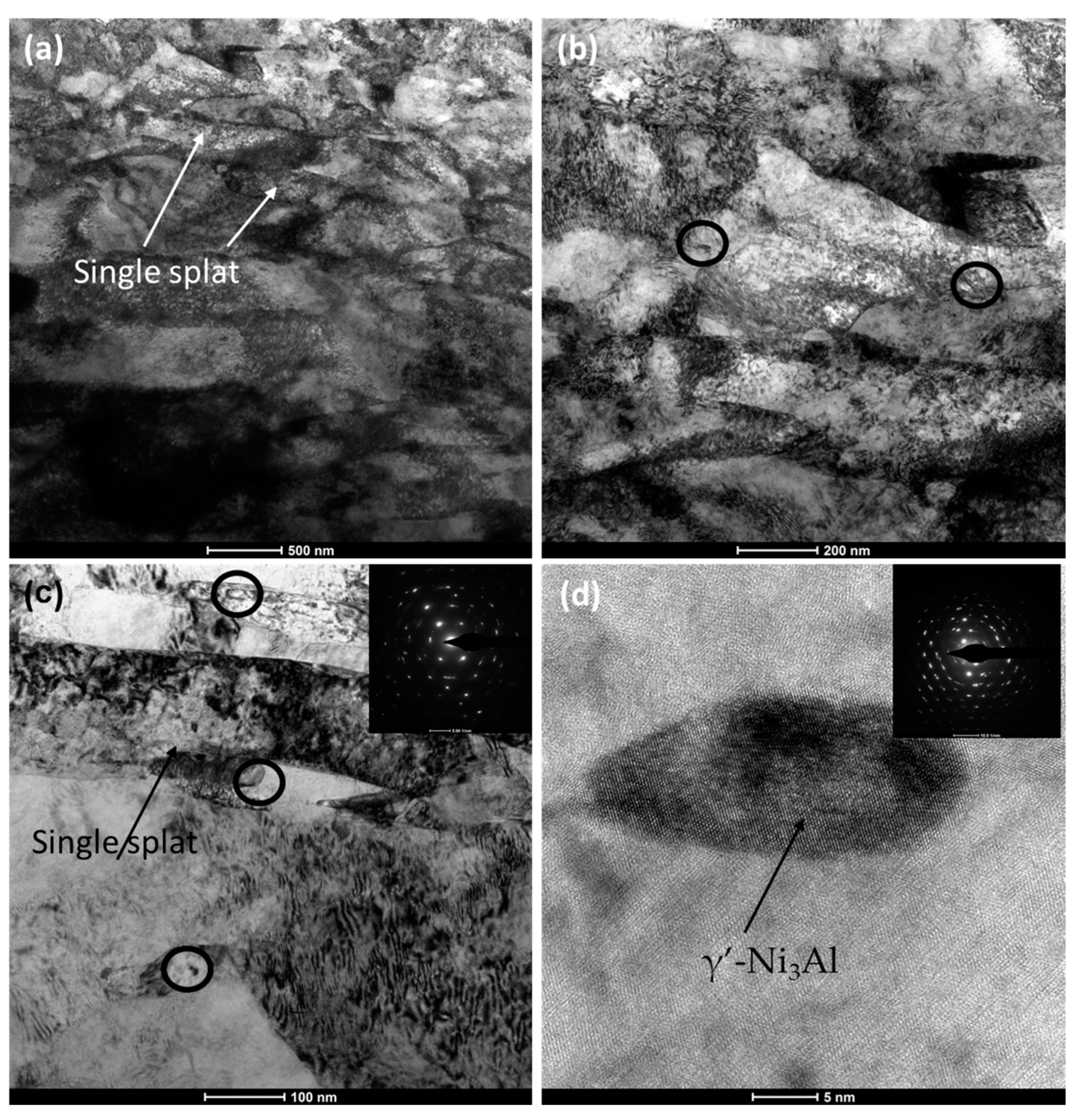
A typical TEM micrograph of the coating in the cross-section is shown in Figure 7. A relatively low-magnification TEM bright field image (Figure 7a) exposes the lamellar-type microstructure of the thermal-sprayed coatings. As stated in the literature, exposure of the agglomerated powders at high temperatures (even for a fraction of seconds) and kinetics during thermal spraying [44,45,46] flattens individual molten/semi-molten droplets of powders against the substrate, producing thin layers or lamellae, often called “splats” [47]. These splats consequently stick on substrate by means of mechanical interlocking as substrate surface is at relatively low temperature than that of the splats. Localised diffusion may also take place to some extent. The constant stream of splats builds up with times, and form thick coatings, having a lamellar structure, constituted from individual thin splats”. The coating thickness was built up by the accumulation of the individual splats with thickness <100 nm (Figure 7a). Higher magnification images (Figure 7b,c) show the existence of the precipitates (marked with circles), individual splats, and eutectic regions (as marked with arrows). Representative high-resolution TEM (HRTEM) image on a precipitate (Figure 7d) confirms the coherency of the precipitate with the matrix, which are metallurgically bonded with the substrate. The selected area diffraction (SAD) parent (as an insert in Figure 7d) was indexed as γ′-Ni3Al on 101 zone axis. The diffraction confirms the polycrystalline aspect of the coating. Besides the γ′-Ni3Al, the other nano-metric precipitation can be associated with the β-NiAl intermetallic phase (around 5–10 nm), which is common in Ni-based superalloys. Thus, it can be concluded that the coating structure was composed of two main phases, which were also supported by the findings in the literature [34].
3.2. In Situ Micro-Pillars Compression
The micro-pillars were fabricated on both the cross-section and the surface of the coatings and disclosed in Figure 8, with higher magnification images as inserts. A 1:3 aspect ratio was maintained to avoid buckling during compression [48]. As evident from Figure 8, the pillars were somewhat tapered (<2°), which was unavoidable due to the ion beam–material interaction [49,50]. At least six individual micro-pillars were fabricated and compressed in each case to ensure data reproducibility.
The computer-controlled software logged the load and displacement during compression, which was then converted in to engineering stress–strain curves (Section 2.2). Figure 9 shows such engineering stress–strain curves in both planar and cross-sectional direction. Though several micro-pillars were compressed, only two representative curves in each case are reported in Figure 9, for a better view/comparison of the curves. However, for micro-mechanical properties calculation, all the graphs were considered, and an average value with standard deviation was reported.
As evident from Figure 9, though the curves on the cross-section and planar direction exhibit similar trends, the magnitude varies considerably. The magnitude of the curves in the cross-section is almost double that of the planar direction. At first, on the introduction of the external loading (compression), the stress increases almost linearly to that of the strain, until it reached the maximum, which is the ultimate compressive strength (UCS). For the curves in the cross-section, the strain was about 7.5% to reach that UCS, whereas for the curves in the planar direction, it was about 5%. After that, the curves in both cases enter in the regions where the stress decreases gradually with the increase till the end of the test. The slight difference among the curves, within a given group, can attributed to the local differences in microstructure. The micro-mechanical properties of the coating as derived from the stress–strain curves are presented in Table 1. The initial linear portion of the stress–strain curves were used to calculate the elastic modulus. As can be seen from Table 1, both yield and ultimate compressive strength in the cross-section is higher than that of the planar direction (1.27 ± 0.10 MPa vs. 0.85 ± 0.09 MPa and 2.19 ± 0.10 GPa vs. 1.20 ± 0.08 GPa, respectively). However, the elastic modulus is comparable in both directions (340.24 ± 31.47 MPa vs. 331.04 ± 29.87 MPa). It was not possible to compare the presented micro-mechanical properties with any literature data, as there were no previous reports available in the literature on that, as of the authors’ best knowledge.
3.3. Analysis of Deformed Micro-Pillars
The exact same micro-pillars, before and after the compression, were compared against each other. Figure 10 represents such comparison of three individual micro-pillars in the cross-section direction. As can be seen from the first row of the images (Figure 10a–c), the micro-pillars contain certain features, such as phase boundaries of different size and shape, before the compression. There was no visible deformation in the initial stage, where the stress rises proportionally to the strain (<7.5% strain). As the compression continued, the pre-existing phase boundaries acted as the ‘weakest link’ and served as a stress raise/crack initiator point. As a ‘weakest link’ in the structure, cracks preferentially took place in these regions in the form of slip planes.
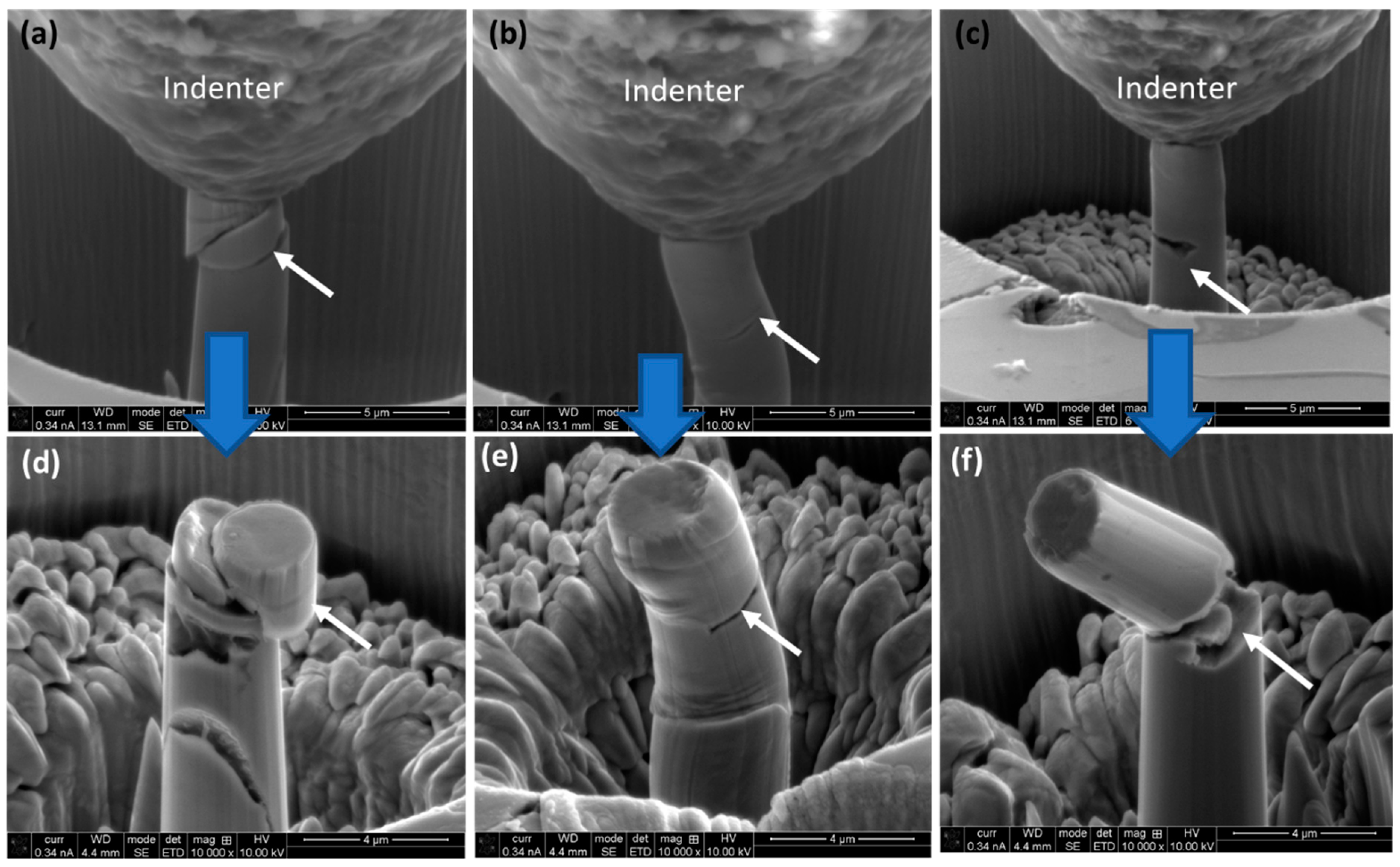
Similar scenarios were also observed in the micro-pillars in planar direction, as shown in Figure 11. As the deformation continues, the micro-pillars can no longer lodge the external loading. As mentioned previously, it is interesting to note that, the ultimate separation (through fracture) took place along the pre-existing phase boundaries in both cases. In the case of a specific micro-pillar (Figure 11b,e), there was no pre-existing secondary phase (Figure 11b). In this particular case, there was no ‘through’ fracture, and the micro-pillar just got squeezed. Thus, it can be concluded that the presence of the pre-existing secondary phases dominates the fracture path of the deformed micro-pillars.
3.4. Deformation Mechanisms
It is important to note that formation and presence of the secondary/ intermetallic phases in the present investigated coating provides a strengthening effect, both at room and at high temperatures [34]. This resembled that of “metal matrix composites [30], where reinforcing particles provide strength, i.e., load bearing capacity, and metal matrix provide toughness, i.e., accommodation of external loading’. Presence of such reinforced particles restrict dislocation movement, and thus increases the strength of the composite, due to Orowan strengthen mechanisms”. The deformation aspect of the coating can be discussed in view of two separate aspects: (i) the contribution of the secondary phase/intermetallic particles, and (ii) loading direction with respect to splat orientation. As discussed in Section 3.1, the surface (planar) and cross-sectional view of the coating microstructure show two different aspects. During compression in the planar direction, the flat punch (indenter) is perpendicular towards the stacked-up splats. As the loading continued, individual splats experienced stress in both radial and vertical direction, and squeezed till cracks took place both through, and along the splat boundaries. On the micro-pillar surface, this is evident as wrinkles (Figure 11e). On the other hand, loading direction is parallel to stacked-up splats on the cross-sectional direction. Thus, formation and propagation of cracks are favourable. These scenarios get more complicated in the presence of the pre-existing phase boundaries in the micro-pillars, which act as the ‘weakest link’ in the structure, as established before. Relative movement took place along the boundaries of those phases, with the rest of the material of the structure. Once the stress level reaches the ‘critically resolved shear stress’, the formation of the slip/shear planes occur. The phase boundaries are metallurgically bonded with the matrix, whereas the splash boundaries are mostly mechanically interlocked. Thus, a relative competition took place regarding which mode of crack propagation will be prevailing.
The above-mentioned mechanism of deformation is supported by the evidence on the stress–strain curves (Figure 9), together with the post-deformation examination of the micro-pillars (Figure 10 and Figure 11). In summary, the presence of both the phase and splat boundaries in the coating structure, and their orientation with respect to loading direction dominate the occurrence and propagation of the cracks. This also heavily contributes on the micro-mechanical properties of the coating. The ‘wrinkles (steps)’ are more pronounced on the deformed pillar surface in the absence of the secondary phases. This means that coating shows relatively lower resistance against deformation.
4. Conclusions
The NiCoCrAlY HEA coating was successfully deposited on the stainless steel subtract. The microstructural evolution of the coating was invested by electron microscopy, and the micro-mechanical properties of the coating was investigated by in situ micro-pillar compression, both in the planar and cross-sectional. Besides that, the deformation aspect of the coating under compression was also explored. Based on the experimental proofs, the following conclusion could be drawn as an outcome of this present study:
- APS-deposited NiCoCrAlY HEA coating attained metallurgical bonding with the substrate, and the as-deposited coating thickness was about 300 μm, with limited porosity (<1%). The coating structure revealed representative lamellar-like structure that are characteristics of thermal-deposited coating, which consisted of the Ni (γ-Ni) matrix solid solution and secondary phase, like β–NiAl, together with the precipitates fine α–Cr and γ′–Ni3Al intermetallics.
- The strength and modulus of elasticity of the coating was higher in the cross-sectional direction (1.27 ± 0.10 MPa of yield strength and 2.19 ± 0.10 GPa of compressive strength), than that of the planar direction (0.85 ± 0.09 MPa of yield strength and 1.20 ± 0.08 GPa of compressive strength). The striking difference was due to the presence of the secondary/intermetallic phases in the micro-pillar, together with that of the loading direction with respect to the splat boundaries orientation.
- The deformation of the coating took place as a result of the wrinkle and slip/shear bands formation once the mechanical loading exceeded the strength of the material.
Author Contributions
A.K.B.: conceptualization, writing, experiment, and supervision; N.R.: resource and writing—review and editing; C.P.: formal analysis, validation, and writing—review and editing; A.P.: writing—review and editing, formal analysis, and validation. All authors have read and agreed to the published version of the manuscript.
Funding
This research received no external funding.
Institutional Review Board Statement
Not applicable.
Informed Consent Statement
Not applicable.
Data Availability Statement
The raw/processed data used to produce the results will be made available by the corresponding author upon reasonable request.
Conflicts of Interest
The authors declare that they have no known competing financial interest or personal relationship whatsoever that could have influenced the work reported in this paper.
References
- Padture, N.P.; Gell, M.; Jordan, E.H. Thermal barrier coatings for gas-turbine engine applications. Science 2002, 296, 280–284. [Google Scholar] [CrossRef] [PubMed]
- Beele, W.; Marijnissen, G.; Van Lieshout, A. The evolution of thermal barrier coatings—Status and upcoming solutions for today’s key issues. Surf. Coat. Technol. 1999, 120, 61–67. [Google Scholar] [CrossRef]
- Cao, X.; Vassen, R.; Stöver, D. Ceramic materials for thermal barrier coatings. J. Eur. Ceram. Soc. 2004, 24, 1–10. [Google Scholar] [CrossRef]
- Hao, E.; An, Y.; Zhao, X.; Zhou, H.; Chen, J. NiCoCrAlYTa coatings on nickel-base superalloy substrate: Deposition by high velocity oxy-fuel spraying as well as investigation of mechanical properties and wear resistance in relation to heat-treatment duration. Appl. Surf. Sci. 2018, 462, 194–206. [Google Scholar] [CrossRef]
- Smialek, J.L.; Miller, R.A. Revisiting the birth of 7YSZ thermal barrier coatings: Stephan Stecura. Coatings 2018, 8, 255. [Google Scholar] [CrossRef]
- Haynes, J. Elevated Temperature Coatings: Science and Technology; TMS: Warrendale, PA, USA, 1999; pp. 185–196. [Google Scholar]
- Kim, J.; Pyeon, J.; Kim, B.-G.; Khadaa, T.; Choi, H.; Zhe, L.; Dube, T.; Zhang, J.; Yang, B.-i.; Jung, Y.-g. Oxidation Behavior of NiCoCrAlY Coatings Deposited by Vacuum Plasma Spraying and High-Velocity Oxygen Fuel Processes. Coatings 2023, 13, 319. [Google Scholar] [CrossRef]
- Schulz, U.; Leyens, C.; Fritscher, K.; Peters, M.; Saruhan-Brings, B.; Lavigne, O.; Dorvaux, J.-M.; Poulain, M.; Mévrel, R.; Caliez, M. Some recent trends in research and technology of advanced thermal barrier coatings. Aerosp. Sci. Technol. 2003, 7, 73–80. [Google Scholar] [CrossRef]
- Wang, Y.; Zhang, C.; Li, J.; Ding, G.; Duan, L. Fabrication and characterization of ITO thin film resistance temperature detector. Vacuum 2017, 140, 121–125. [Google Scholar] [CrossRef]
- Bates, B.; Witman, J.; Zhang, Y. Electrolytic co-deposition of Ni-CrAlY composite coatings using different deposition configurations. Mater. Manuf. Process. 2016, 31, 1232–1237. [Google Scholar] [CrossRef]
- Tancret, F.; Bhadeshia, H.; MacKay, D. Design of a creep resistant nickel base superalloy for power plant applications: Part 1-Mechanical properties modelling. Mater. Sci. Technol. 2003, 19, 283–290. [Google Scholar] [CrossRef]
- Marginean, G.; Utu, D. Cyclic oxidation behaviour of different treated CoNiCrAlY coatings. Appl. Surf. Sci. 2012, 258, 8307–8311. [Google Scholar] [CrossRef]
- Nijdam, T.; Kwakernaak, C.; Sloof, W. The effects of alloy microstructure refinement on the short-term thermal oxidation of NiCoCrAlY alloys. Metall. Mater. Trans. A 2006, 37, 683–693. [Google Scholar] [CrossRef]
- Kim, D.; Shin, I.; Koo, J.; Kim, S.; Seo, D.; Kim, J.; Seok, C. Quantitative analysis on the depletion rate of β-NiAl phases in MCrAlY coating. J. Mech. Sci. Technol. 2014, 28, 513–519. [Google Scholar] [CrossRef]
- Toscano, J.; Vaβen, R.; Gil, A.; Subanovic, M.; Naumenko, D.; Singheiser, L.; Quadakkers, W. Parameters affecting TGO growth and adherence on MCrAlY-bond coats for TBC’s. Surf. Coat. Technol. 2006, 201, 3906–3910. [Google Scholar] [CrossRef]
- Wang, B.; Gong, J.; Sun, C.; Huang, R.; Wen, L. The behavior of MCrAlY coatings on Ni3Al-base superalloy. Mater. Sci. Eng. A 2003, 357, 39–44. [Google Scholar] [CrossRef]
- Hou, X.; Zhang, C.; Wang, F.; Ding, G. Fabrication and characterization of NiCoCrAlY coating deposited on nickel-based superalloy substrates. Vacuum 2018, 155, 55–59. [Google Scholar] [CrossRef]
- Gudmundsson, B.; Jacobson, B.; Gruner, H. The influence of substrate temperature on the microstructure and hardness of vacuum-plasma-sprayed Co–Ni–Cr–Al–Si–Zr–Y and Co–Ni–Cr–Al–Y alloys. Mater. Sci. Eng. A 1989, 108, 105–115. [Google Scholar] [CrossRef]
- Noguchi, K.; Nishida, M.; Chiba, A. Transmission electron microscopy of low pressure plasma sprayed CoNiCrAlY coating. Scr. Mater. 1996, 35, 1359–1364. [Google Scholar] [CrossRef]
- Basak, A.; Matteazzi, P.; Vardavoulias, M.; Celis, J.-P. Corrosion–wear behaviour of thermal sprayed nanostructured FeCu/WC–Co coatings. Wear 2006, 261, 1042–1050. [Google Scholar] [CrossRef]
- Basak, A.K.; Celis, J.-P.; Vardavoulias, M.; Matteazzi, P. Effect of nanostructuring and Al alloying on friction and wear behaviour of thermal sprayed WC–Co coatings. Surf. Coat. Technol. 2012, 206, 3508–3516. [Google Scholar] [CrossRef]
- Hou, G.; An, Y.; Zhao, X.; Zhou, H.; Chen, J. Effect of alumina dispersion on oxidation behavior as well as friction and wear behavior of HVOF-sprayed CoCrAlYTaCSi coating at elevated temperature up to 1000 C. Acta Mater. 2015, 95, 164–175. [Google Scholar] [CrossRef]
- Zhang, L.-w.; Lu, L.; Wang, L.; Ning, X.-j.; Wang, Q.-s.; Wang, R.-x. Microstructural characteristics and oxidation behavior of low-pressure cold-sprayed CoNiCrAlY coatings. J. Therm. Spray Technol. 2017, 26, 1565–1572. [Google Scholar] [CrossRef]
- Brandl, W.; Toma, D.; Krüger, J.; Grabke, H.; Matthäus, G. The oxidation behaviour of HVOF thermal-sprayed MCrAlY coatings. Surf. Coat. Technol. 1997, 94, 21–26. [Google Scholar] [CrossRef]
- Tang, F.; Ajdelsztajn, L.; Schoenung, J.M. Characterization of oxide scales formed on HVOF NiCrAlY coatings with various oxygen contents introduced during thermal spraying. Scr. Mater. 2004, 51, 25–29. [Google Scholar] [CrossRef]
- Lee, C.; Kim, H.; Choi, H.; Ahn, H. Phase transformation and bond coat oxidation behavior of plasma-sprayed zirconia thermal barrier coating. Surf. Coat. Technol. 2000, 124, 1–12. [Google Scholar] [CrossRef]
- Kawakita, J.; Kuroda, S.; Fukushima, T.; Kodama, T. Development of dense corrosion resistant coatings by an improved HVOF spraying process. Sci. Technol. Adv. Mater. 2003, 4, 281–289. [Google Scholar] [CrossRef]
- Radhika, N.; Noble, N.; Adediran, A.A. Electrochemical and hot corrosion behaviour of annealed AlCoCrFeNi HEA coating over steel. Sci. Rep. 2024, 14, 5652. [Google Scholar] [CrossRef] [PubMed]
- Noble, N.; Radhika, N.; Sathishkumar, M.; Basak, A. Slurry erosion behaviour of AlCoCrFeNi high entropy alloy coating prepared by atmospheric plasma spraying. Trans. IMF 2024, 1–8. [Google Scholar] [CrossRef]
- Basak, A.; Pramanik, A.; Prakash, C. Deformation and strengthening of SiC reinforced Al-MMCs during in-situ micro-pillar compression. Mater. Sci. Eng. A 2019, 763, 138141. [Google Scholar] [CrossRef]
- Tabbakh, T.; Alshihri, S.; Basak, A.; Kurdi, A. Strength of a 3D printed Al 7068 alloy under micro-pillar compression. Met. Mater. Int. 2022, 28, 2706–2718. [Google Scholar] [CrossRef]
- Kurdi, A.; Basak, A. Deformation of electrodeposited gradient Co/Sn multilayered coatings under micro-pillar compression. Eng. Fract. Mech. 2018, 204, 138–146. [Google Scholar] [CrossRef]
- Catto, F.; Gabriel, A.; Bolfarini, C.; Kiminami, C.S.; Afonso, C.R.M. Rapid solidification and laser cladding of gas atomized Ni-Nb-Sn bulk metallic glass. In Materials Science Forum; Trans Tech Publications Ltd.: Stafa-Zurich, Switzerland, 2017; pp. 311–316. [Google Scholar]
- Falcón, J.C.P.; Echeverria, A.; Afonso, C.R.; Carrullo, J.C.Z.; Borrás, V.A. Microstructure assessment at high temperature in NiCoCrAlY overlay coating obtained by laser metal deposition. J. Mater. Res. Technol. 2019, 8, 1761–1772. [Google Scholar] [CrossRef]
- Kiener, D.; Motz, C.; Dehm, G. Micro-compression testing: A critical discussion of experimental constraints. Mater. Sci. Eng. A 2009, 505, 79–87. [Google Scholar] [CrossRef]
- Girault, B.; Schneider, A.S.; Frick, C.P.; Arzt, E. Strength effects in micropillars of a dispersion strengthened superalloy. Adv. Eng. Mater. 2010, 12, 385–388. [Google Scholar] [CrossRef]
- Tang, J.; Bai, Y.; Zhang, J.; Liu, K.; Liu, X.; Zhang, P.; Wang, Y.; Zhang, L.; Liang, G.; Gao, Y. Microstructural design and oxidation resistance of CoNiCrAlY alloy coatings in thermal barrier coating system. J. Alloys Compd. 2016, 688, 729–741. [Google Scholar] [CrossRef]
- Liang, J.; Wei, H.; Hou, G.; Zheng, Q.; Sun, X.; Guan, H.; Hu, Z. Thermal stability of phases in a NiCoCrAlY coating alloy. J. Mater. Res. 2008, 23, 2264–2274. [Google Scholar] [CrossRef]
- Yuan, K.; Peng, R.L.; Li, X.-H.; Johansson, S. Hot corrosion behavior of HVOF-sprayed CoNiCrAlYSi coatings in a sulphate environment. Vacuum 2015, 122, 47–53. [Google Scholar] [CrossRef]
- Huntz, A. Influence of active elements on the oxidation mechanism of M–Cr–Al alloys. Mater. Sci. Eng. 1987, 87, 251–260. [Google Scholar] [CrossRef]
- Stott, F.; Wood, G. Growth and adhesion of oxide scales on Al2O3-forming alloys and coatings. Mater. Sci. Eng. 1987, 87, 267–274. [Google Scholar] [CrossRef]
- Smeggil, J. Some comments on the role of yttrium in protective oxide scale adherence. Mater. Sci. Eng. 1987, 87, 261–265. [Google Scholar] [CrossRef]
- Volenik, K.; Novak, V.; Dubský, J.; Chraska, P.; Neufuss, K. Properties of alloy steel coatings oxidized during plasma spraying. Mater. Sci. Eng. A 1997, 234, 493–496. [Google Scholar] [CrossRef]
- Buschow, K. Encyclopedia of Materials: Science and Technology; Elsevier: Amsterdam, The Netehrlands, 2001. [Google Scholar]
- Basak, A.; Celis, J.-P.; Ponthiaux, P.; Wenger, F.; Vardavoulias, M.; Matteazzi, P. Effect of nanostructuring and Al alloying on corrosion behaviour of thermal sprayed WC–Co coatings. Mater. Sci. Eng. A 2012, 558, 377–385. [Google Scholar] [CrossRef]
- Basak, A.; Achanta, S.; De Bonte, M.; Celis, J.-P.; Vardavoulias, M.; Matteazzi, P. Effect of Al and Cr addition on tribological behaviour of HVOF and APS nanostructured WC–Co coatings. Trans. IMF 2007, 85, 310–315. [Google Scholar] [CrossRef]
- Basak, A.; Achanta, S.; Celis, J.-P.; Vardavoulias, M.; Matteazzi, P. Structure and mechanical properties of plasma sprayed nanostructured alumina and FeCuAl–alumina cermet coatings. Surf. Coat. Technol. 2008, 202, 2368–2373. [Google Scholar] [CrossRef]
- Misra, A.; Hirth, J.; Hoagland, R. Length-scale-dependent deformation mechanisms in incoherent metallic multilayered composites. Acta Mater. 2005, 53, 4817–4824. [Google Scholar] [CrossRef]
- Wang, J.; Stanford, N. Investigation of precipitate hardening of slip and twinning in Mg5% Zn by micropillar compression. Acta Mater. 2015, 100, 53–63. [Google Scholar] [CrossRef]
- Zhang, J.; Liu, G.; Lei, S.; Niu, J.; Sun, J. Transition from homogeneous-like to shear-band deformation in nanolayered crystalline Cu/amorphous Cu–Zr micropillars: Intrinsic vs. extrinsic size effect. Acta Mater. 2012, 60, 7183–7196. [Google Scholar] [CrossRef]
Figure 1.
SEM micrographs on NiCoCrAlY coating: (a) cross-sectional and (b) planar view after metallographic polishing.
Figure 1.
SEM micrographs on NiCoCrAlY coating: (a) cross-sectional and (b) planar view after metallographic polishing.

Figure 2.
High-magnification SEM micrographs on the cross-section of the NiCoCrAlY coating: (a) secondary electron (SE) and (b) back-scattered electron (BSE) images after metallographic polishing.
Figure 2.
High-magnification SEM micrographs on the cross-section of the NiCoCrAlY coating: (a) secondary electron (SE) and (b) back-scattered electron (BSE) images after metallographic polishing.
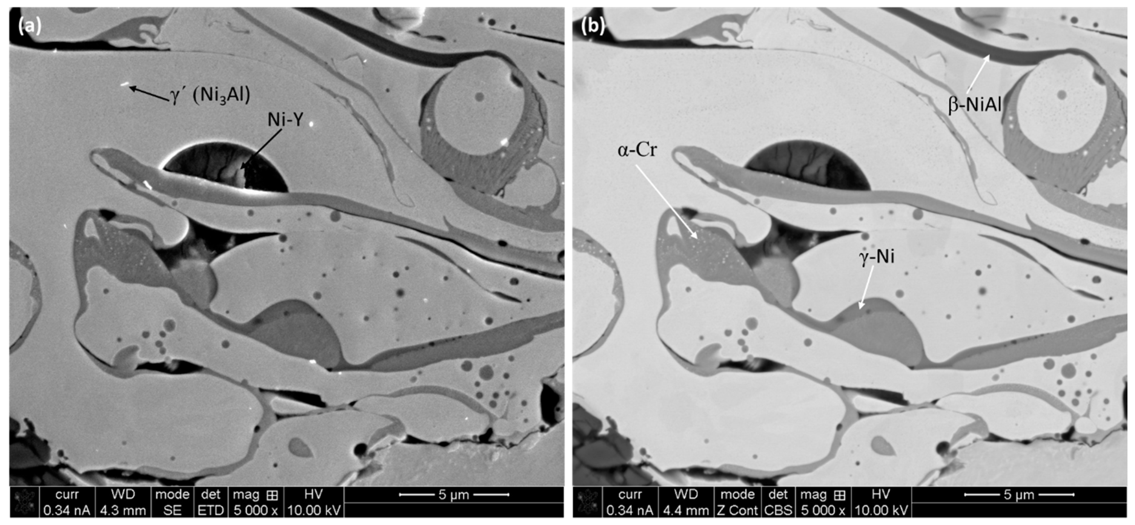
Figure 3.
(a) High-magnification SEM micrograph on the cross-section of the NiCoCrAlY coating. The indicated points in the image are the locations of the EDX analysis. (b–j) EDS spectra obtained from the locations indicated in (a).
Figure 3.
(a) High-magnification SEM micrograph on the cross-section of the NiCoCrAlY coating. The indicated points in the image are the locations of the EDX analysis. (b–j) EDS spectra obtained from the locations indicated in (a).


Figure 4.
Elemental mapping on the cross-section of the NiCoCrAlY coating: (a) EDS layered image, (b) Ni map, (c) Co map, (d) Cr map, (e) Al map, (f) Y map, and (g) map sum spectrum.
Figure 4.
Elemental mapping on the cross-section of the NiCoCrAlY coating: (a) EDS layered image, (b) Ni map, (c) Co map, (d) Cr map, (e) Al map, (f) Y map, and (g) map sum spectrum.
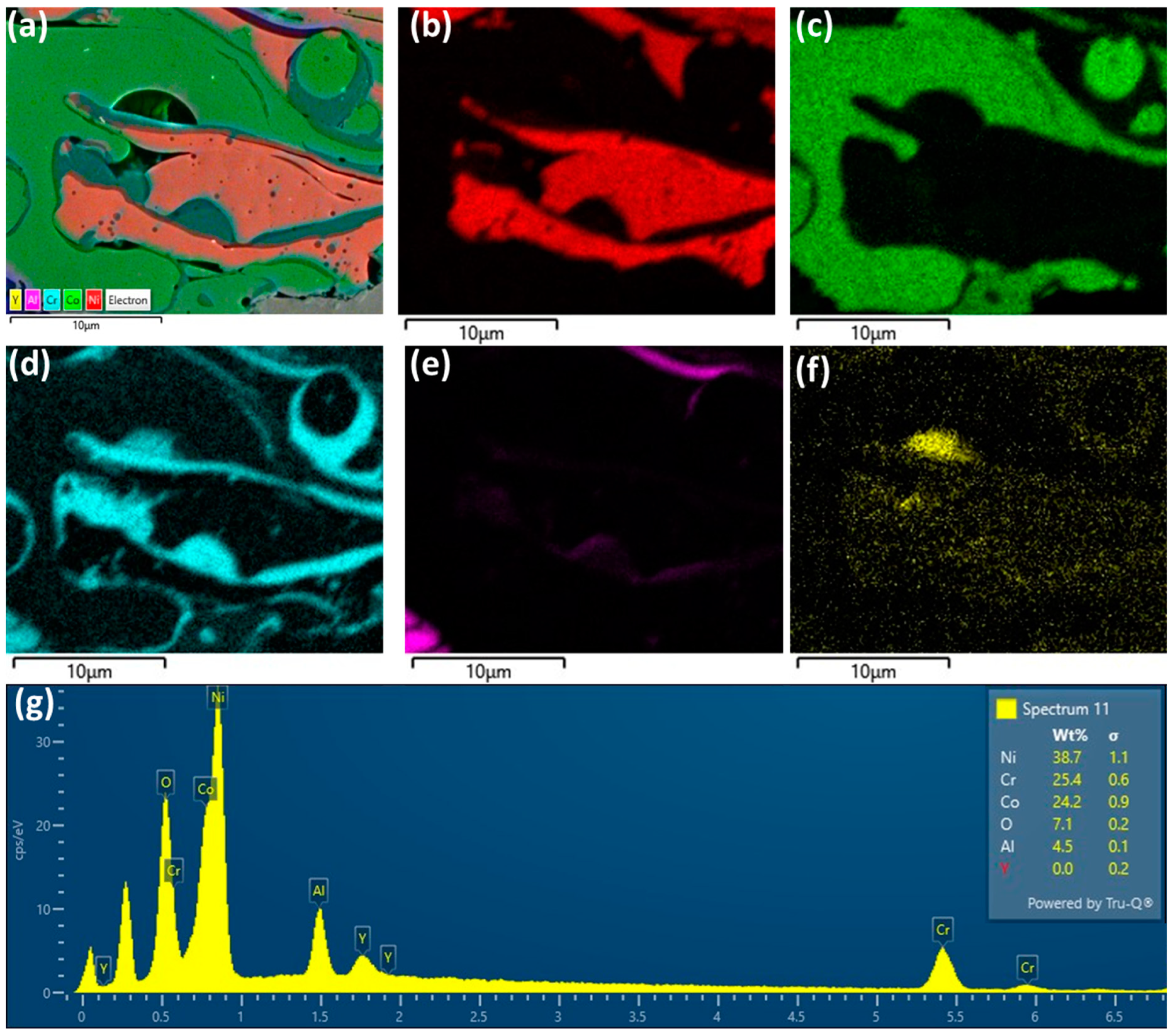
Figure 5.
Elemental mapping on the surface (planar) of the NiCoCrAlY coating: (a) EDS layered image, (b) Ni map, (c) Co map, (d) Cr map, (e) Al map, (f) Y map, and (g) map sum spectrum.
Figure 5.
Elemental mapping on the surface (planar) of the NiCoCrAlY coating: (a) EDS layered image, (b) Ni map, (c) Co map, (d) Cr map, (e) Al map, (f) Y map, and (g) map sum spectrum.

Figure 6.
X-ray diffraction spectra on as-sprayed NiCoCrAlY coating.

Figure 7.
Representative TEM micrographs on the coating cross-section: (a) overall all view of the coating showing individual ‘splats’, (b,c) higher magnification images, and (d) HR-TEM image with corresponding SAD pattern of γ′-Ni3Al on 101 zone axis, as an insert.
Figure 7.
Representative TEM micrographs on the coating cross-section: (a) overall all view of the coating showing individual ‘splats’, (b,c) higher magnification images, and (d) HR-TEM image with corresponding SAD pattern of γ′-Ni3Al on 101 zone axis, as an insert.

Figure 8.
A series of as-fabricated micro-pillars on the (a) cross-section and (b) planar direction of the coating. Enlarged 45° view of the micro-pillars are shown as an insert.
Figure 8.
A series of as-fabricated micro-pillars on the (a) cross-section and (b) planar direction of the coating. Enlarged 45° view of the micro-pillars are shown as an insert.
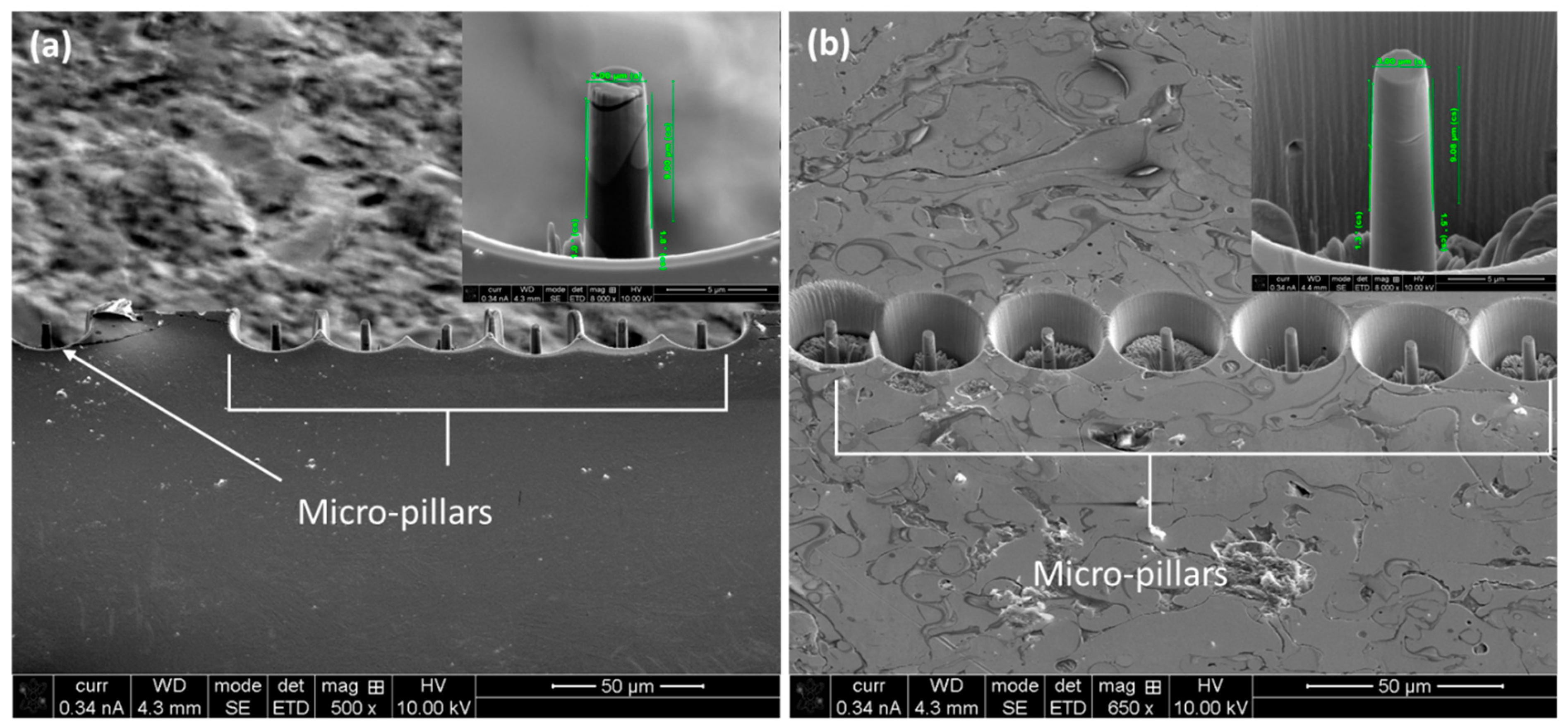
Figure 9.
Average engineering stress–strain curves on the planar and cross-section direction of the NiCoCrAlY coating subjected to in situ micro-pillar compression.
Figure 9.
Average engineering stress–strain curves on the planar and cross-section direction of the NiCoCrAlY coating subjected to in situ micro-pillar compression.
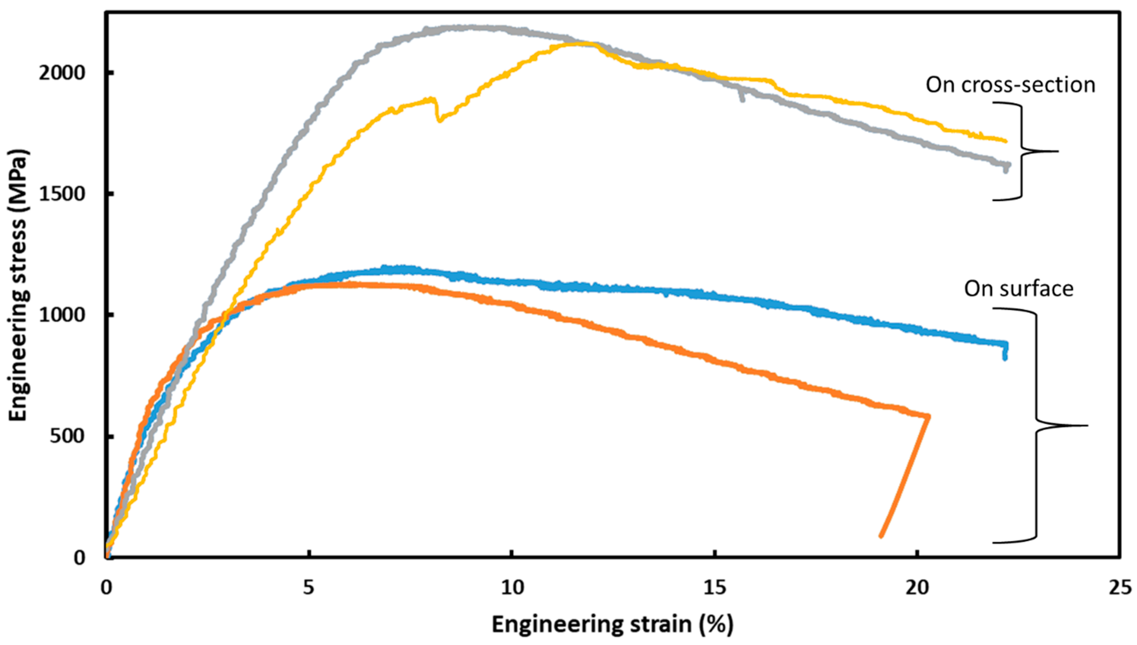
Figure 10.
Deformed micro-pillars (45° tilted SEM view) after compression on cross-sectional direction. State of the micropillars at the beginning of compression (a–c) and at the end of compression (d–f). The white arrows indicate the fracture lines.
Figure 10.
Deformed micro-pillars (45° tilted SEM view) after compression on cross-sectional direction. State of the micropillars at the beginning of compression (a–c) and at the end of compression (d–f). The white arrows indicate the fracture lines.
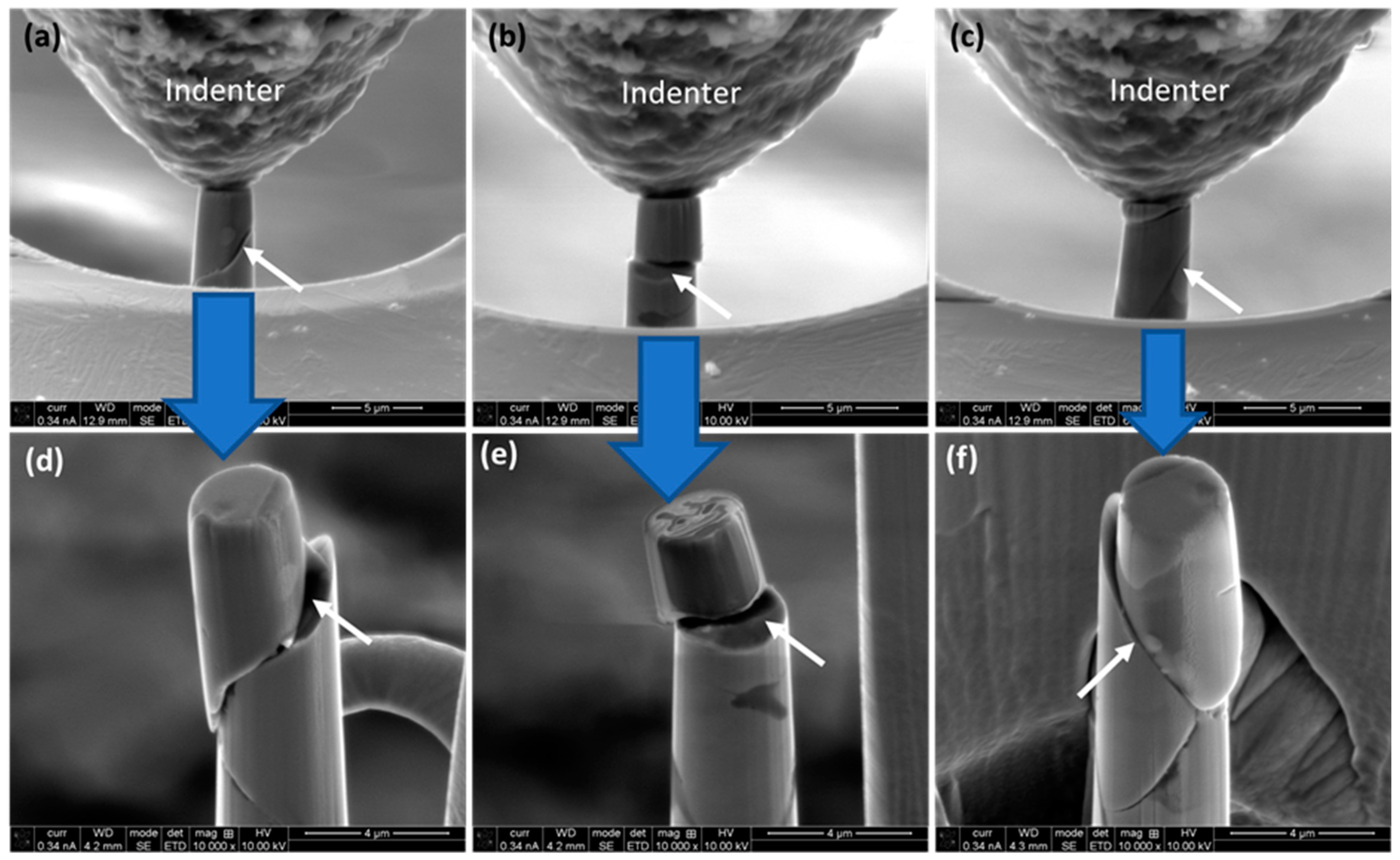
Figure 11.
Deformed micro-pillars (45° tilted SEM view) after compression on planar direction. State of the micropillars at the beginning of compression (a–c) and at the end of compression (d–f). The white arrows indicate the fracture lines.
Figure 11.
Deformed micro-pillars (45° tilted SEM view) after compression on planar direction. State of the micropillars at the beginning of compression (a–c) and at the end of compression (d–f). The white arrows indicate the fracture lines.

Table 1.
Mechanical properties of the NiCoCrAlY coating in the cross-section and planar direction calculated from the stress–strain curves.
Table 1.
Mechanical properties of the NiCoCrAlY coating in the cross-section and planar direction calculated from the stress–strain curves.
| NiCoCrAlY Coating | Yield Strength (σy), MPa | Ultimate Compressive Strength (σUCS), GPa | Elastic Modulus (E), MPa |
|---|---|---|---|
| Planar direction | 0.85 ± 0.09 | 1.20 ± 0.08 | 331.04 ± 29.87 |
| Cross-sectional direction | 1.27 ± 0.10 | 2.19 ± 0.10 | 340.24 ± 31.47 |
Disclaimer/Publisher’s Note: The statements, opinions and data contained in all publications are solely those of the individual author(s) and contributor(s) and not of MDPI and/or the editor(s). MDPI and/or the editor(s) disclaim responsibility for any injury to people or property resulting from any ideas, methods, instructions or products referred to in the content. |
© 2024 by the authors. Licensee MDPI, Basel, Switzerland. This article is an open access article distributed under the terms and conditions of the Creative Commons Attribution (CC BY) license (https://creativecommons.org/licenses/by/4.0/).
Share and Cite
MDPI and ACS Style
Basak, A.K.; Radhika, N.; Prakash, C.; Pramanik, A. Investigation on the Microstructure and Micro-Mechanical Properties of Thermal-Sprayed NiCoCrAlY High Entropy Alloy Coating. Designs 2024, 8, 37. https://doi.org/10.3390/designs8020037
AMA Style
Basak AK, Radhika N, Prakash C, Pramanik A. Investigation on the Microstructure and Micro-Mechanical Properties of Thermal-Sprayed NiCoCrAlY High Entropy Alloy Coating. Designs. 2024; 8(2):37. https://doi.org/10.3390/designs8020037
Chicago/Turabian StyleBasak, Animesh Kumar, Nachimuthu Radhika, Chander Prakash, and Alokesh Pramanik. 2024. "Investigation on the Microstructure and Micro-Mechanical Properties of Thermal-Sprayed NiCoCrAlY High Entropy Alloy Coating" Designs 8, no. 2: 37. https://doi.org/10.3390/designs8020037