
Failure Investigation of under Construction Prestressed Concrete Bridge in Chitwan, Nepal

 ,
, 
 and
and 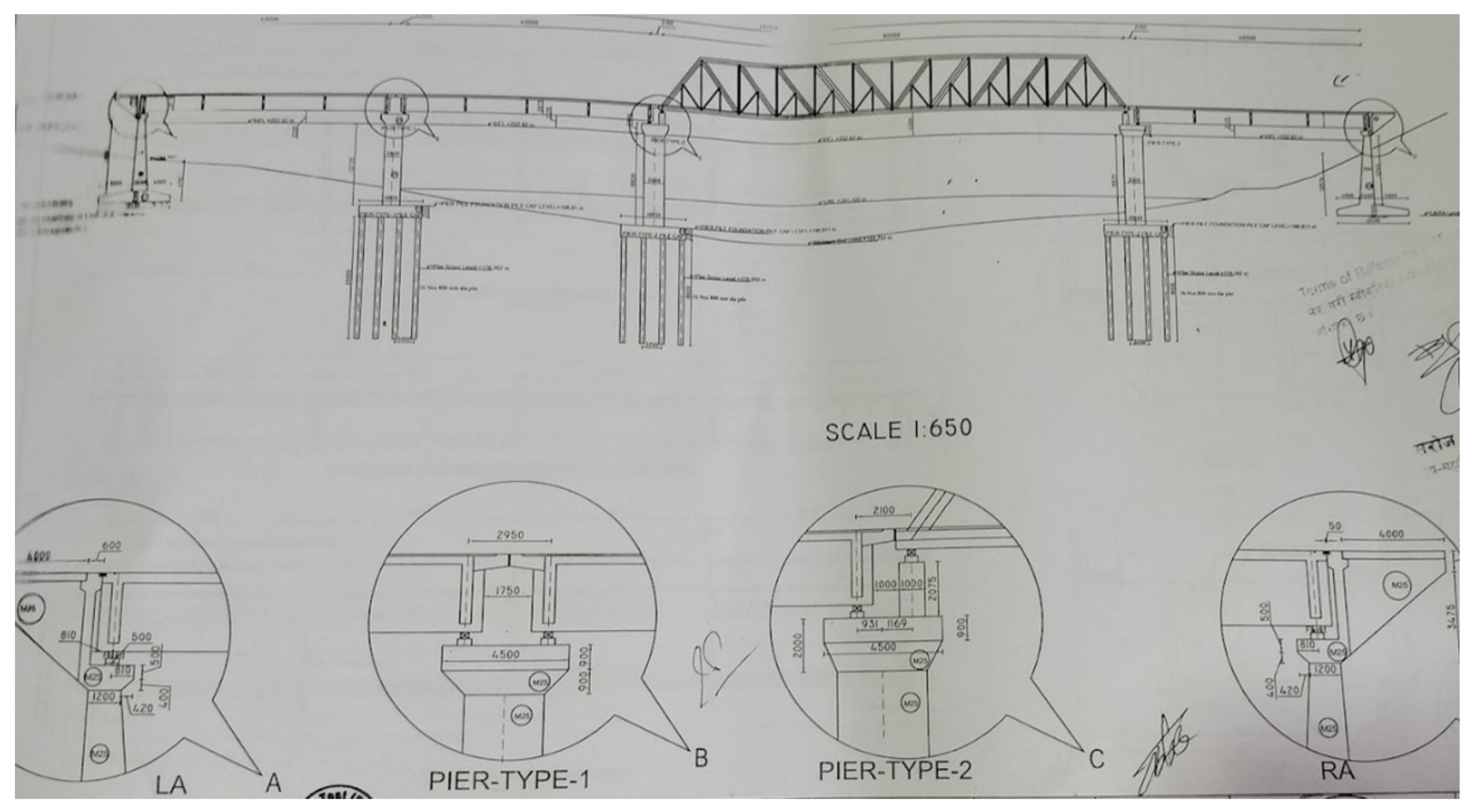
Abstract
:1. Background
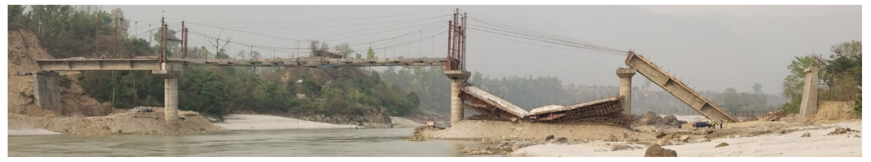
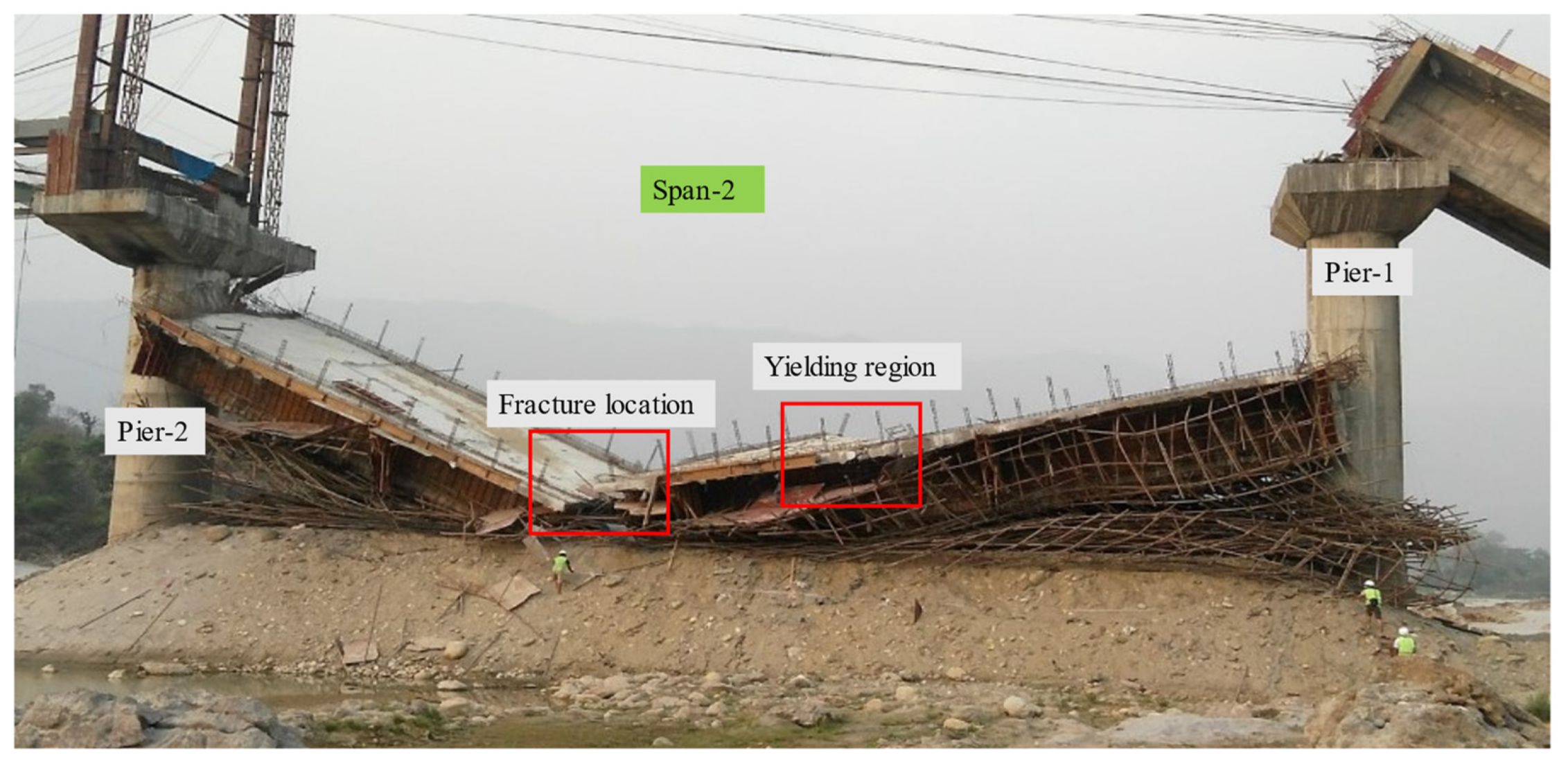
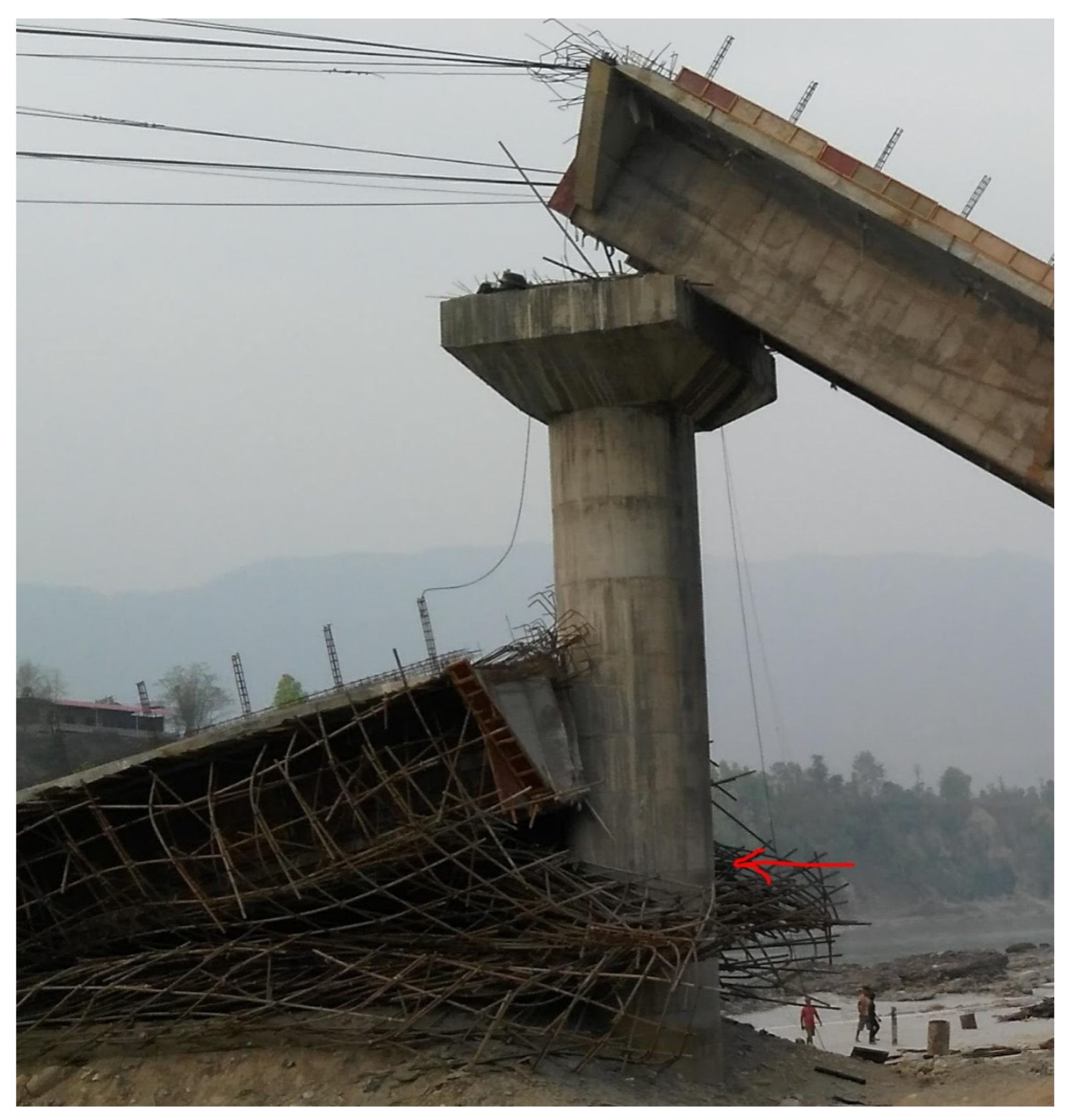
2. Thimura Prestressed Bridge Collapse
3. Overview of Bridge Construction System
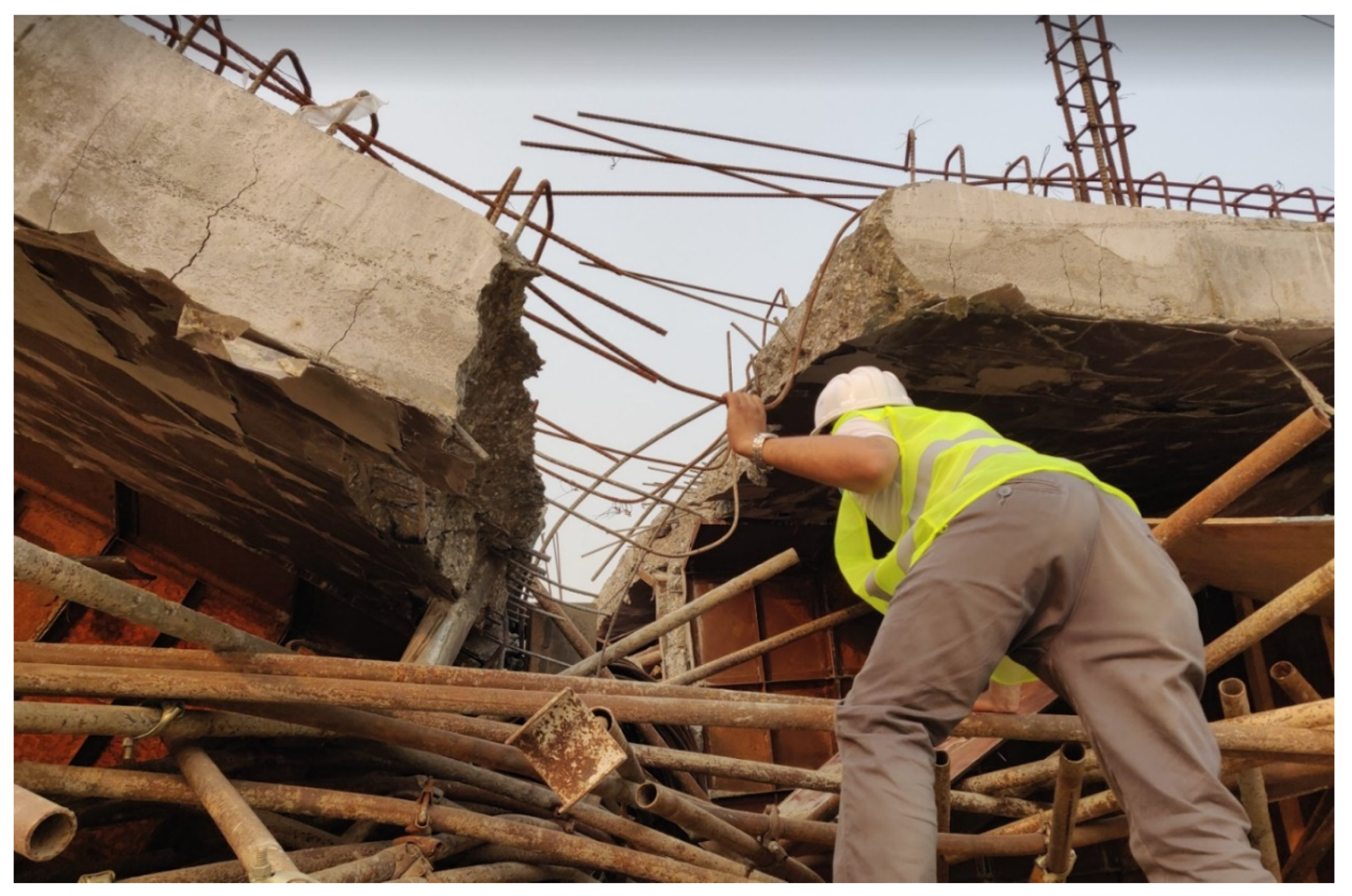
4. Forensic Damage Assessment
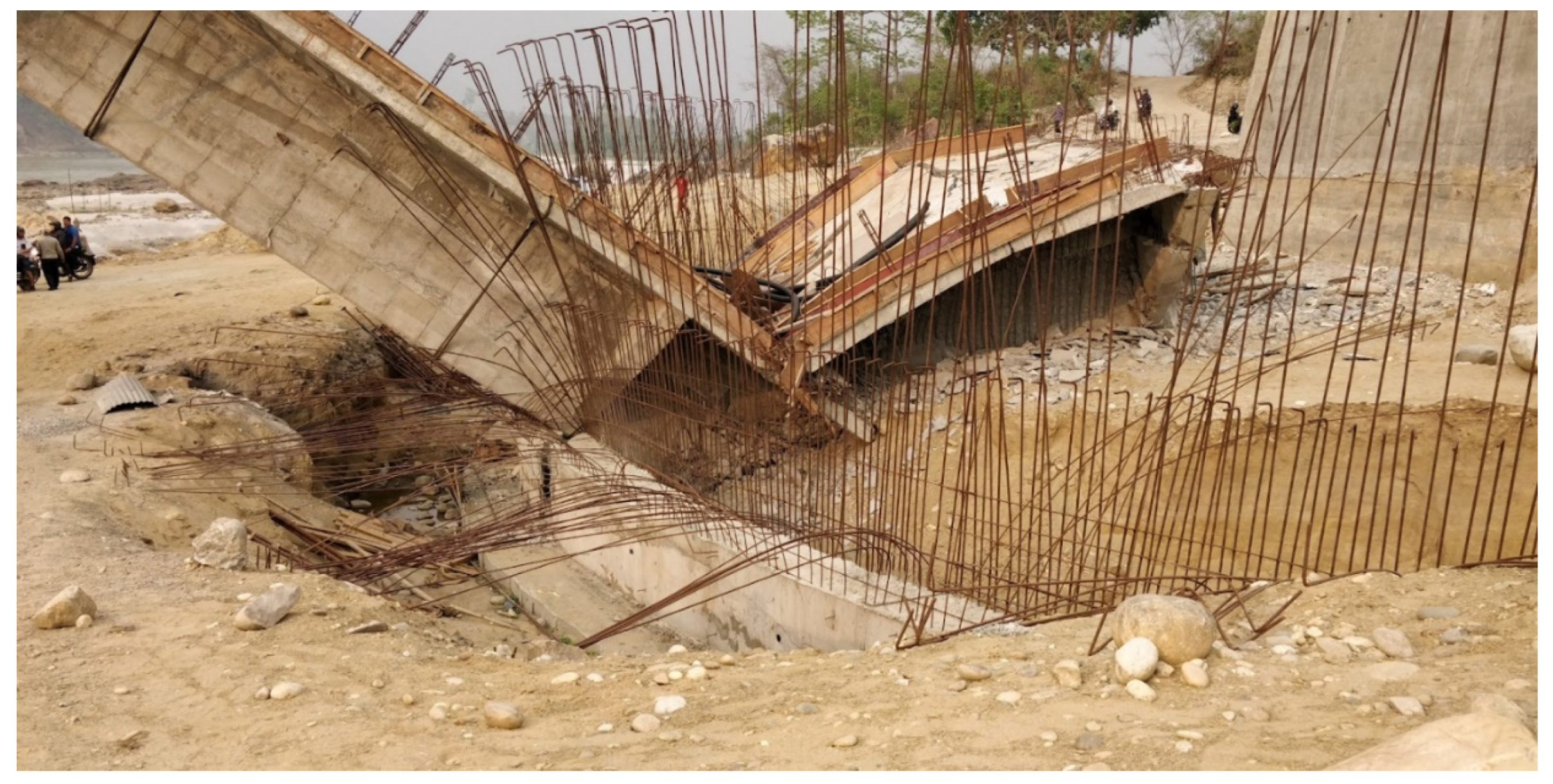
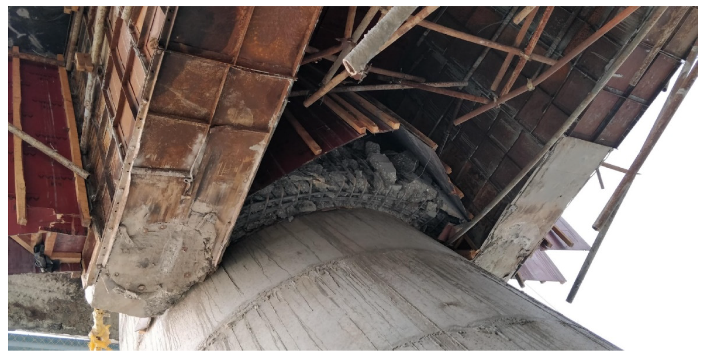
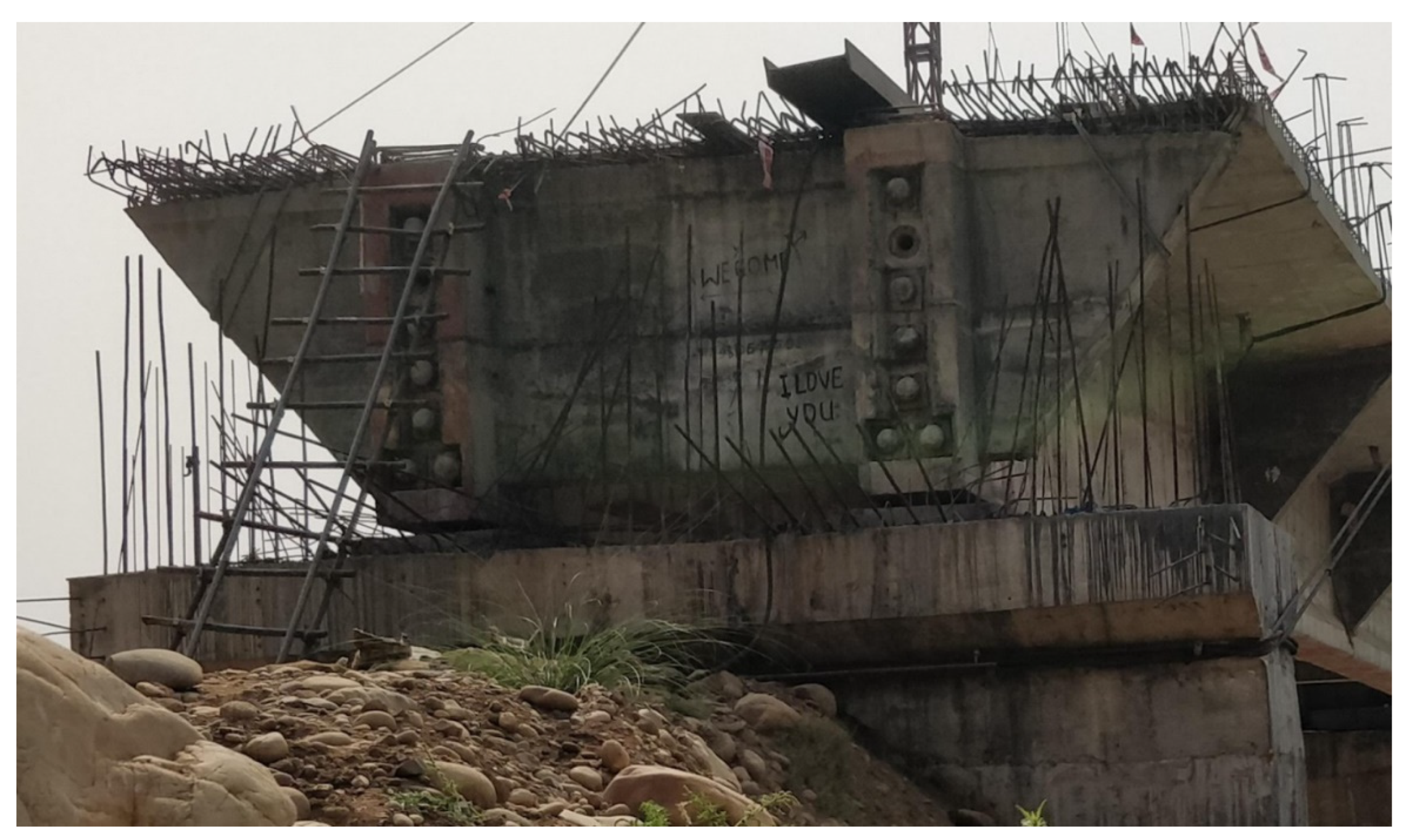
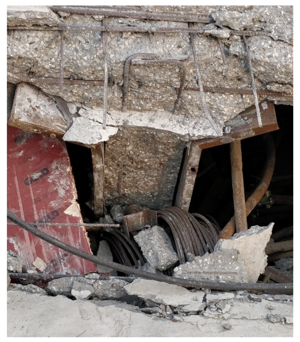
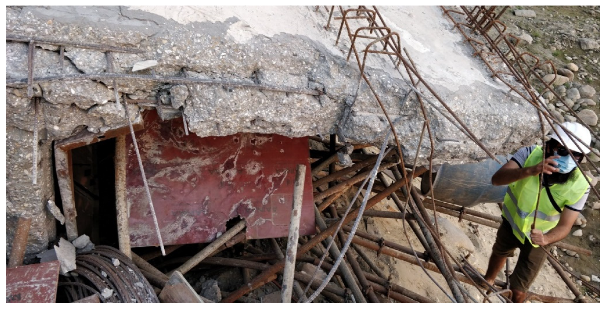
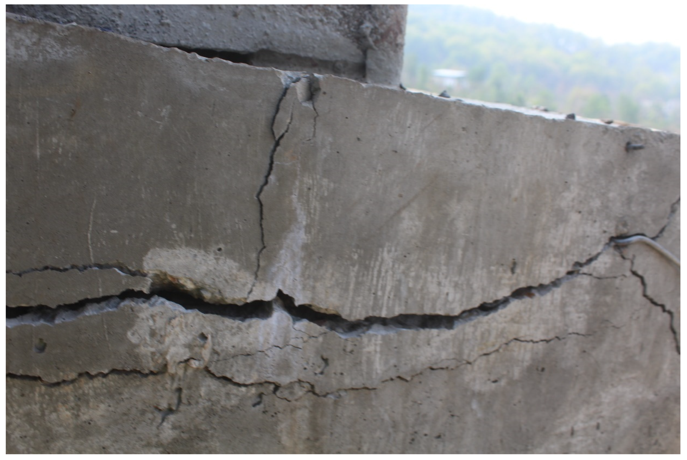
4.1. Damage to Beams
4.2. Damage to Slab
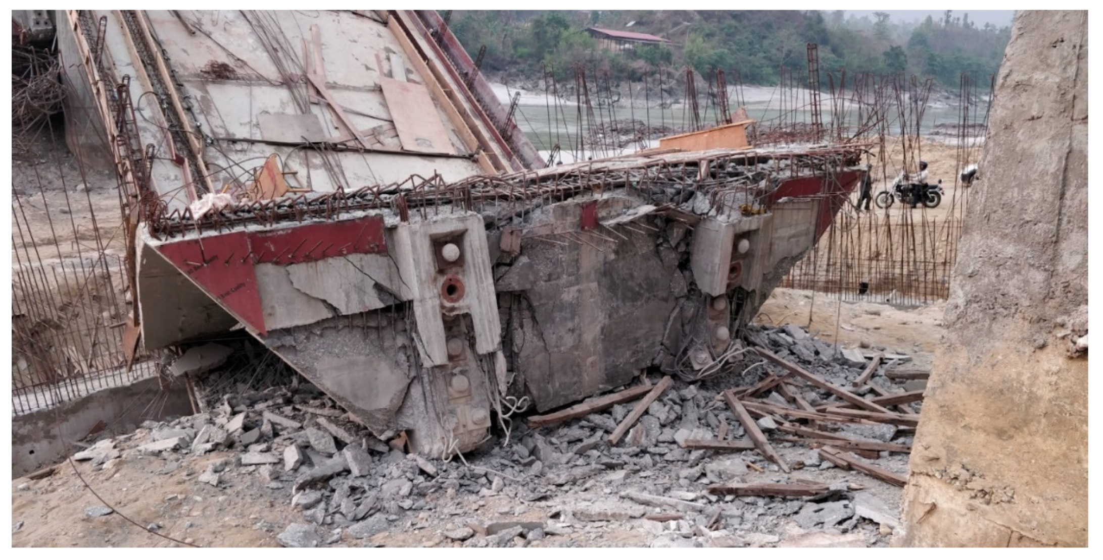
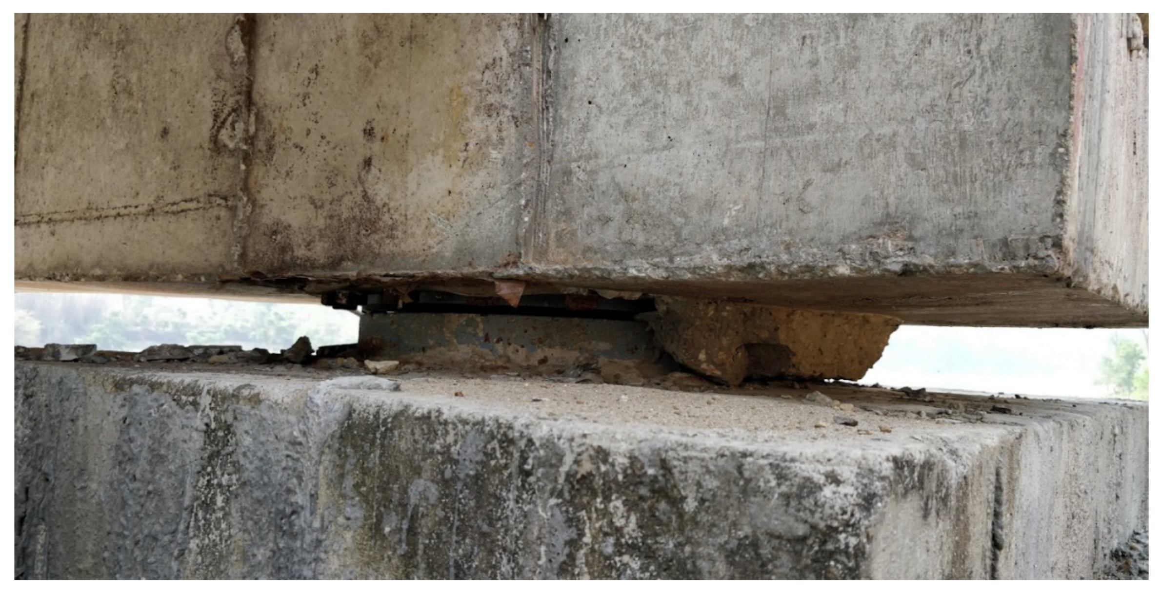
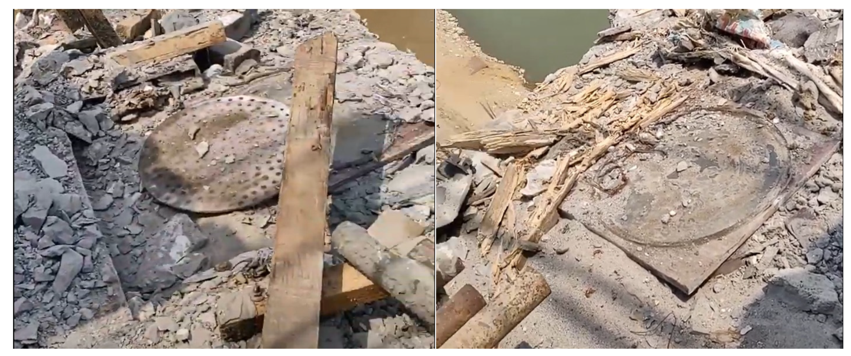
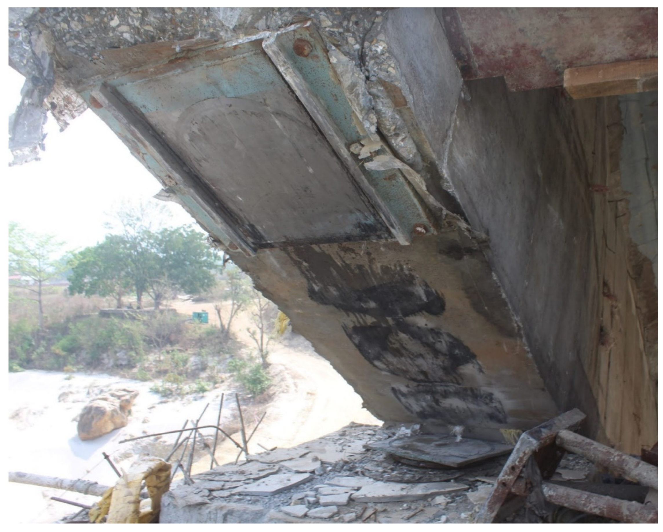
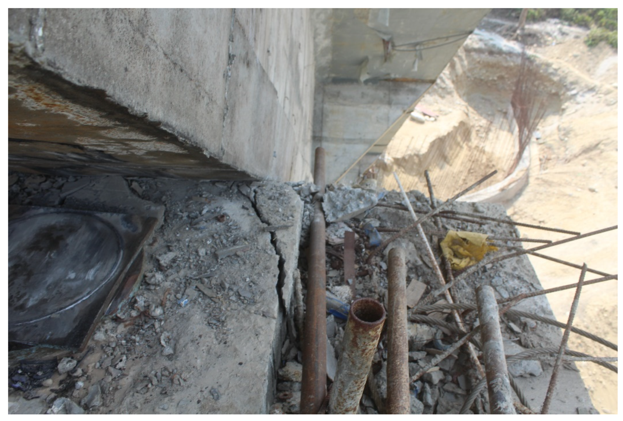
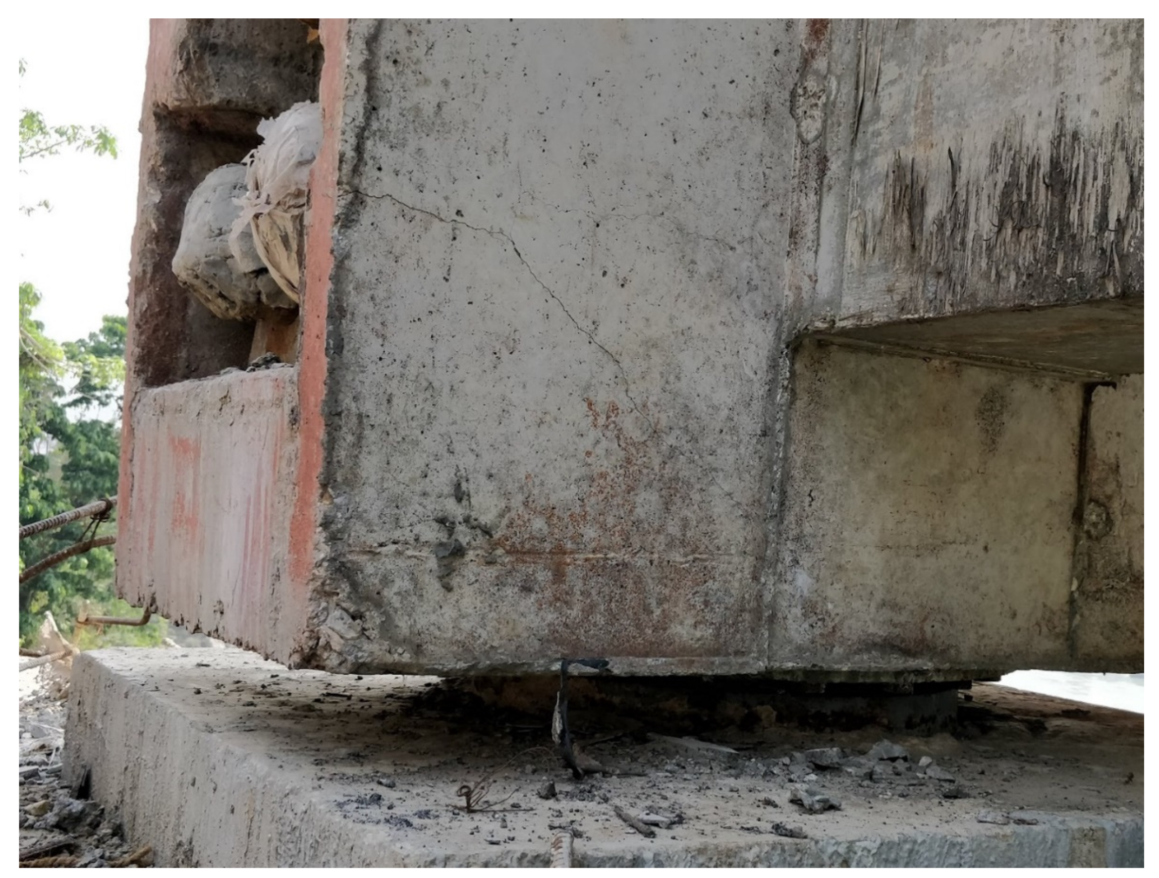
4.3. Damage to Bearings
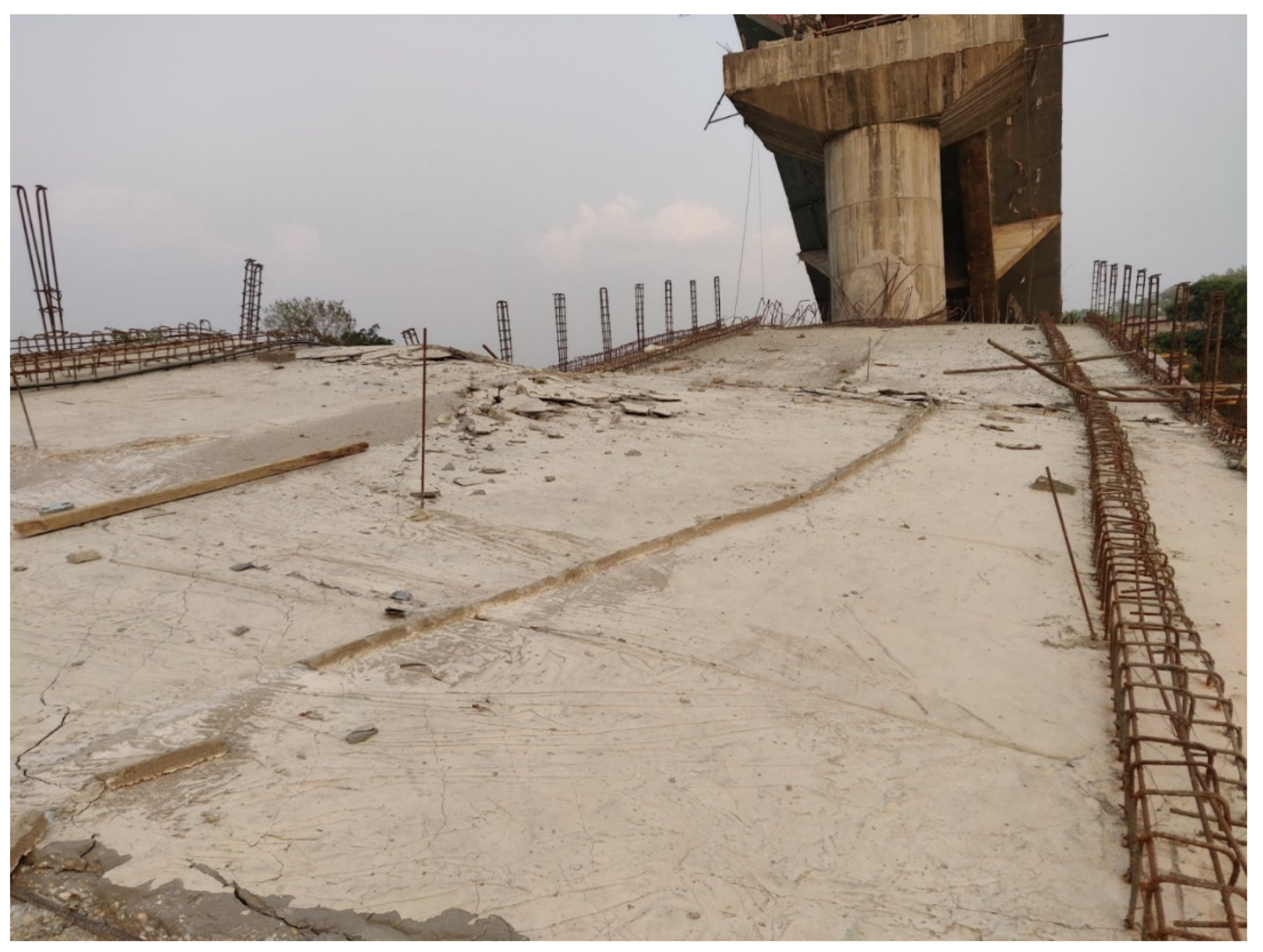
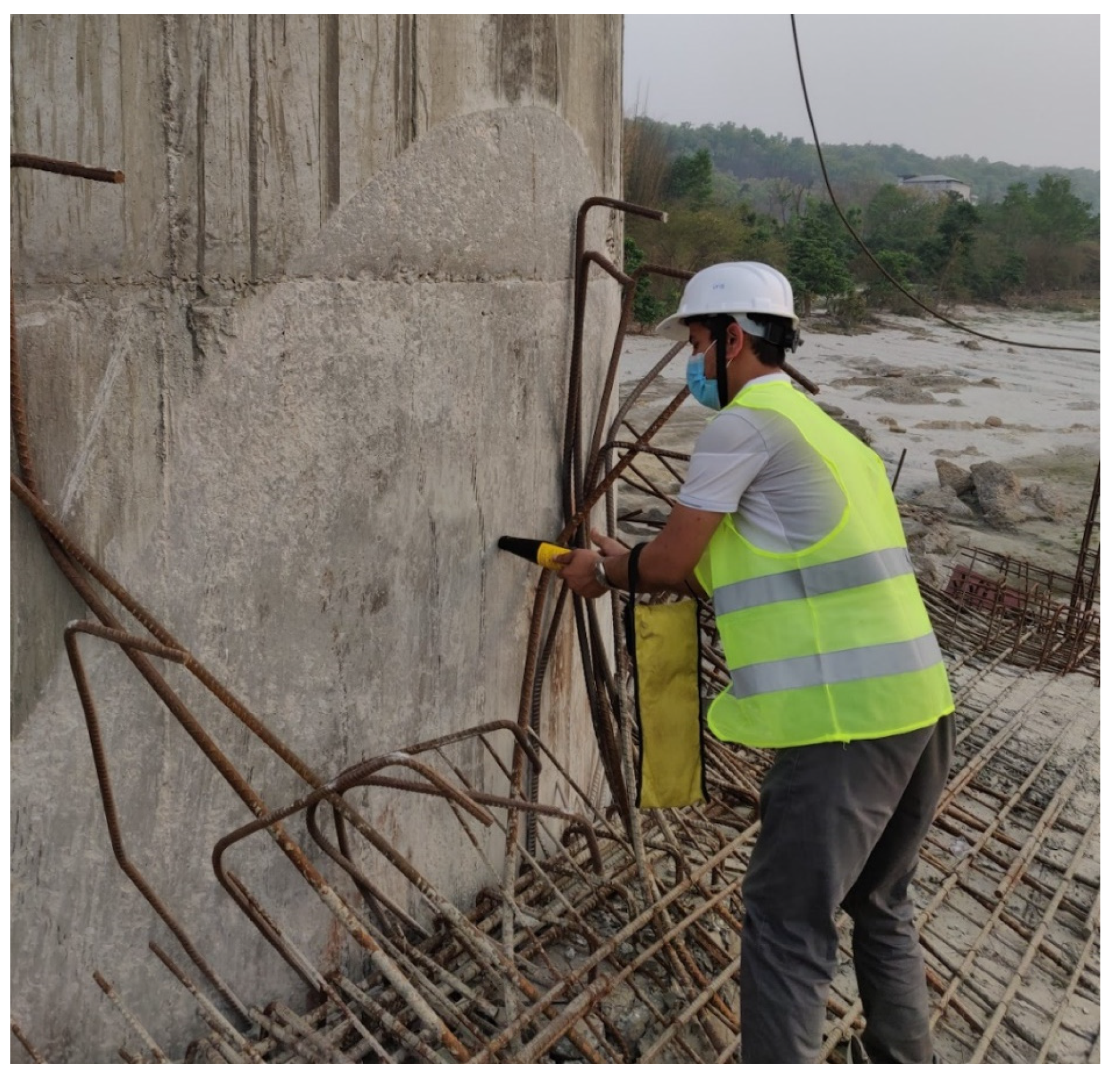
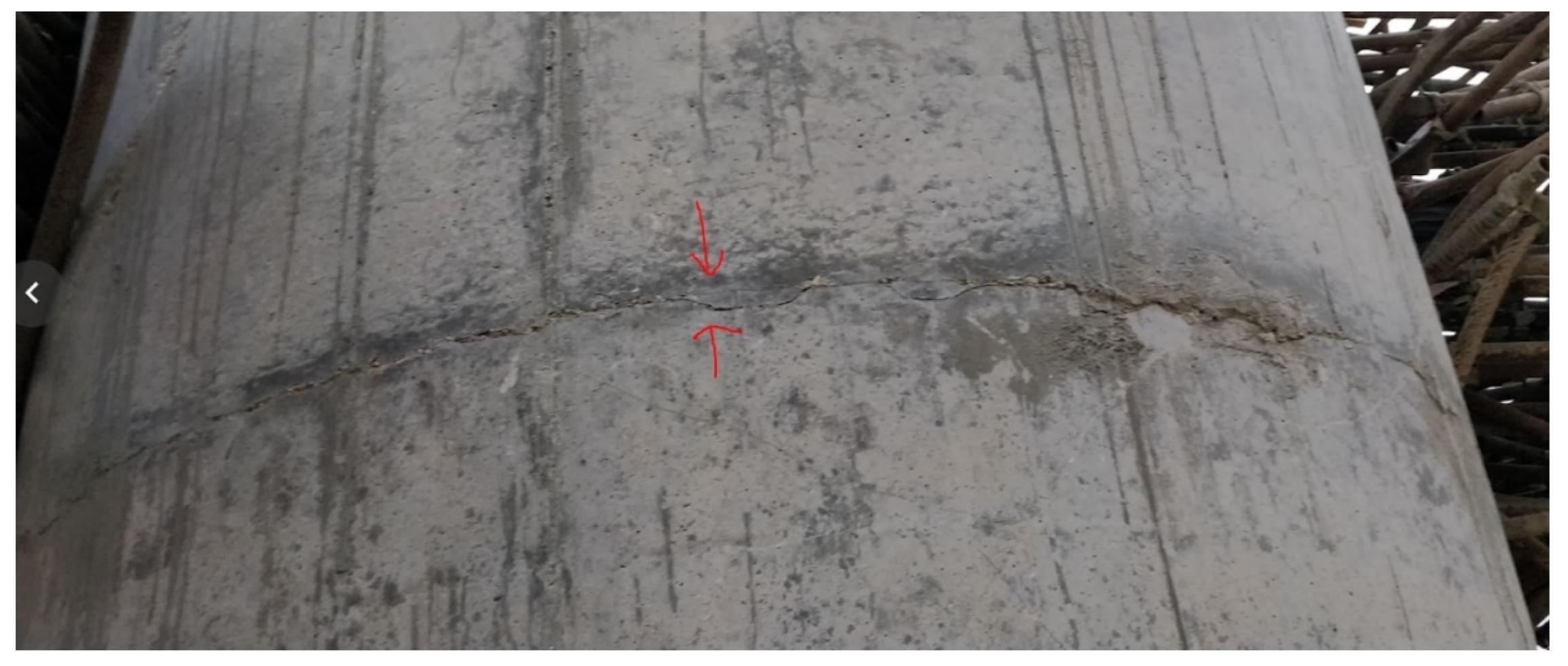
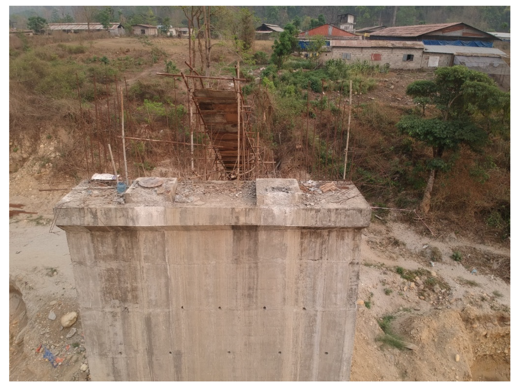
4.4. Damage to Pier
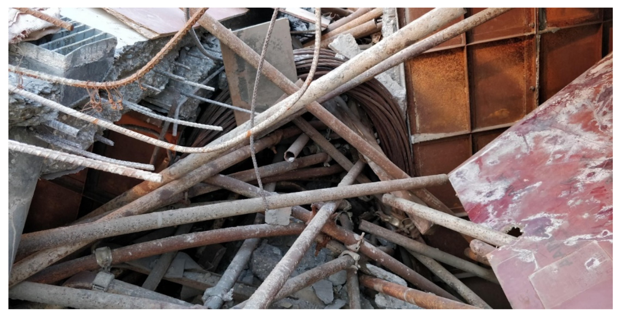
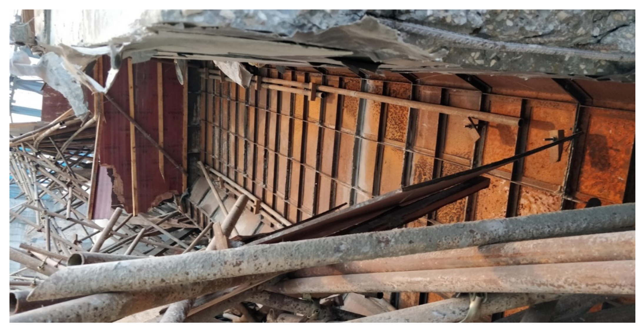
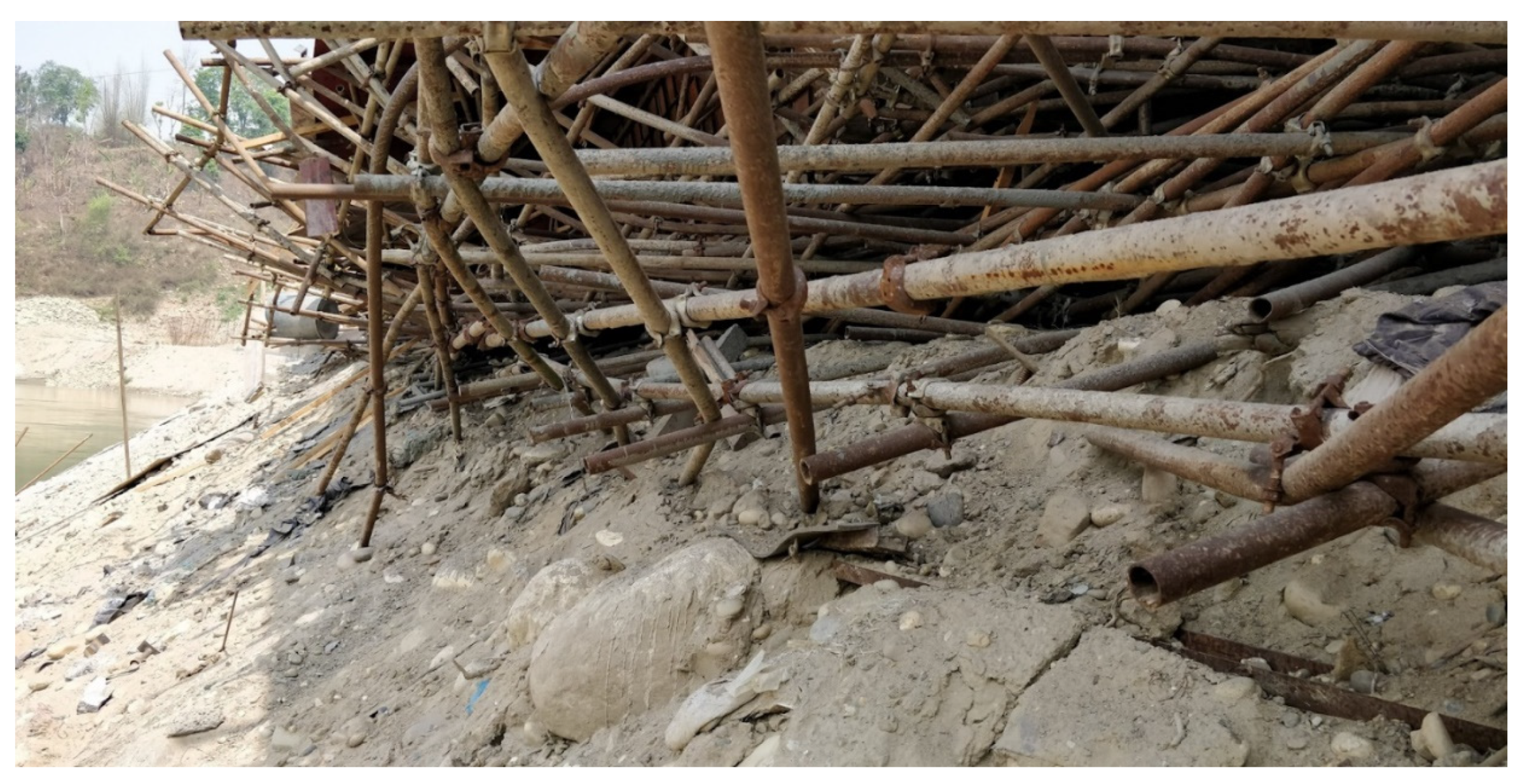
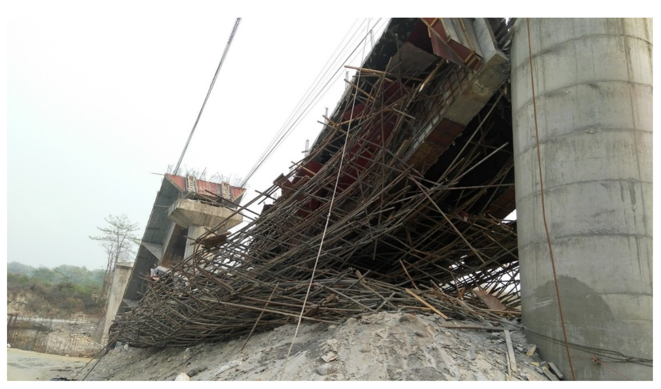
4.5. Damage to Formwork and Falsework
4.6. Other Damages
5. The Failure Sequence
- There was a gradual settlement of falsework supporting the steel league of Span-2 on the downstream side (Figure 28). The settlement was caused by a gradual displacement of loose sand that was piled up to downscale the height of the falsework. The main hypothesis was that the collapse occurred as the rate of settlement had increased once curing was stopped five days prior to the collapse. This may be due to the fact that the water content was lost from the loose soil. In addition, small triggers, such as the vibration from the generator operating beside the embankment used by the steel erection team, as well as human movements, may have caused a significant displacement of loose sand;
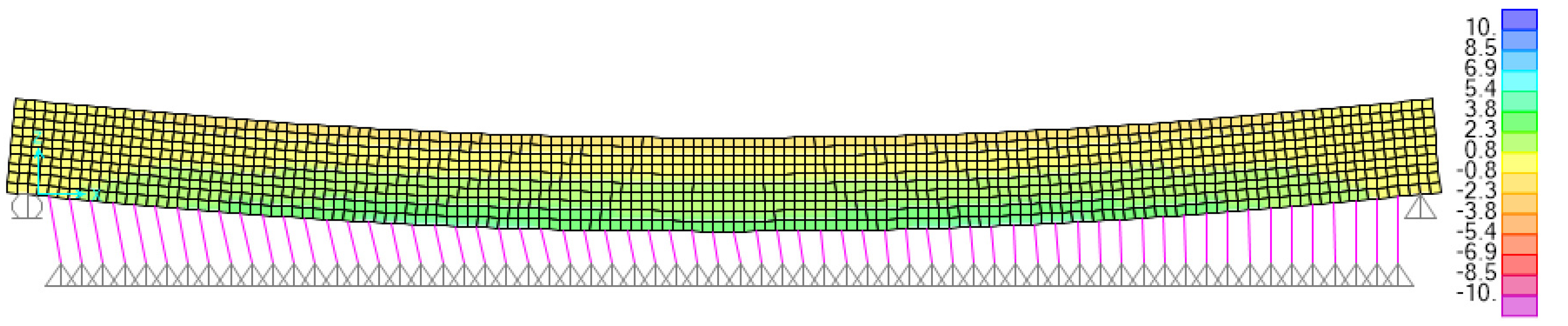
- The settlement of the falsework induced a high bending moment on the to-be-prestressed concrete deck of Span-2. It was even greater towards the downstream side where the settlement was also larger;
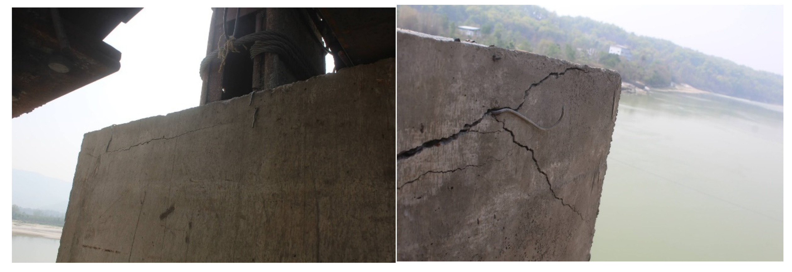
- After about 250 mm of settlement (measured in situ during reconnaissance), the longitudinal rebars of the downstream-side beam fractured, and progressively, there was high bending on slab rebars, causing several flexural cracks near the beam-fracture location;
- There was a second settlement of 300 mm that caused an instability of the edge props and the redistribution of force to the falsework and the deck at the upstream side. Consequently, the upstream props buckled, causing the flexure failure of the upstream-side beam together with a sudden weakening of the whole section, and ultimately the collapse of the whole deck;
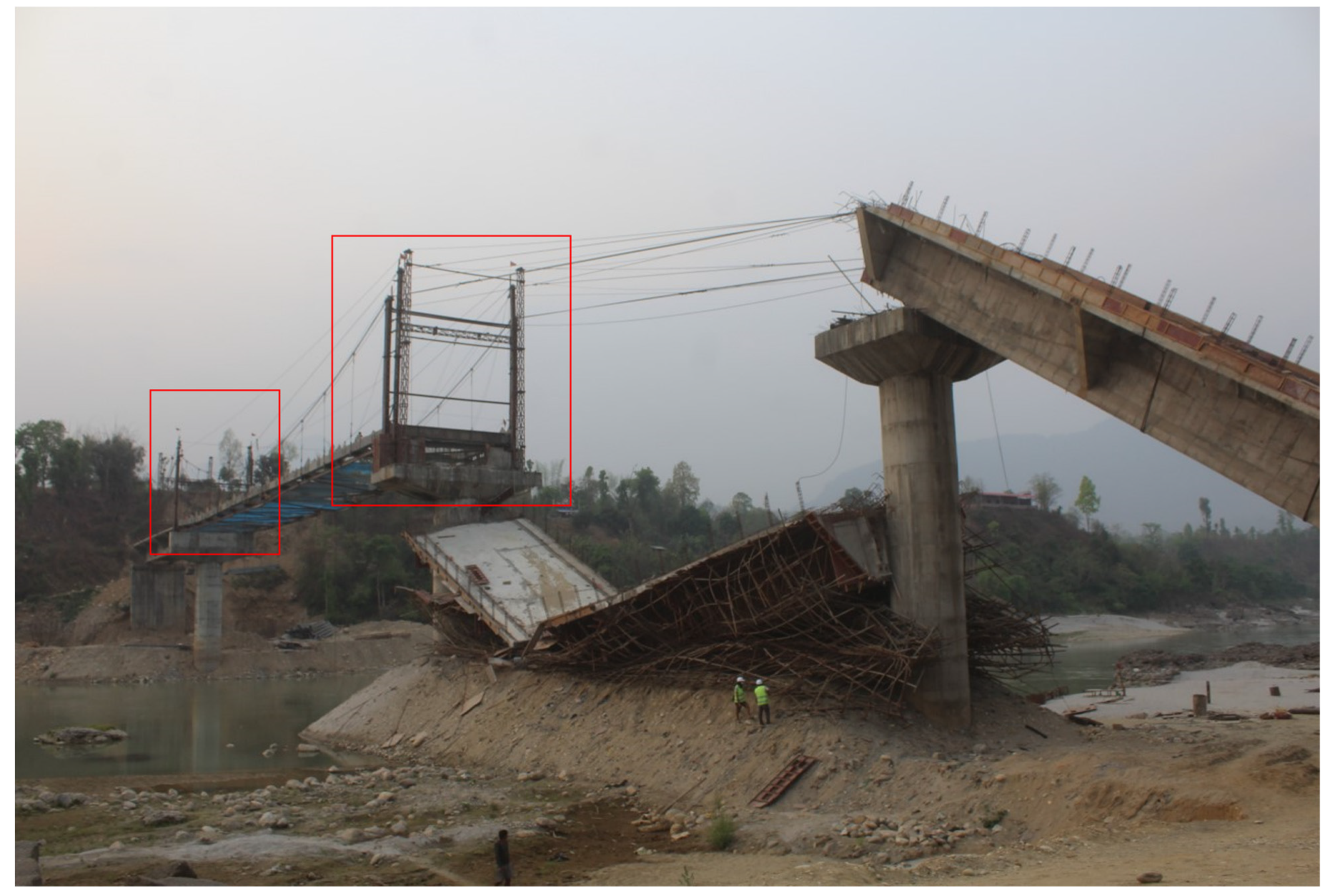
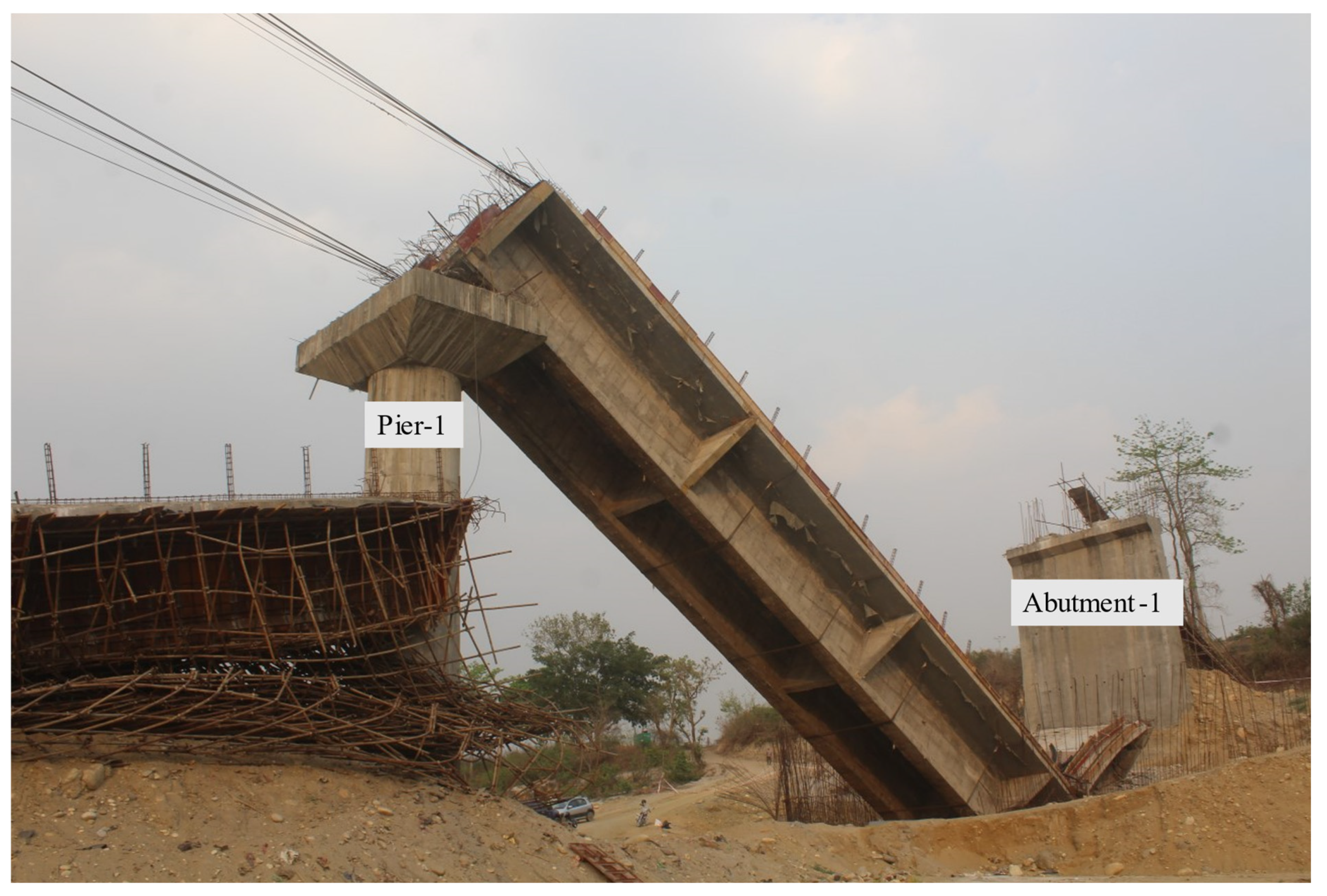
- During the collapse process of Span-2, Pier-1 was pushed towards Abutment-1. Pier-2 was pushed towards the Pier-3 side, causing a rapid increase of tensile force in the cables anchored to the Span-1 deck that were used to support the steel span during the erection process. This force caused the horizontal sliding of Span-1 towards Pier-1, causing both the failure of the bearings and the detachment of Abutment-1. The sliding left several bearing marks on the soffit of the beam. It started because the tension on the cable increased and caused the failure of the hinge bearing over Abutment-1. Then, due to the residual tension in the cable, and due to the lack of proper anchorage, sliding continued;
- Hinging over Pier-1, the Abutment-1 side of the deck fell off with a rotational motion and subsequently hit the ground with a large impact force;
- The failure of Span-2 was initiated first, but the falling was relatively gradual, as depicted by the friction and scouring impressions on both piers. After the Span-2 collapse was initiated, the displacement (and subsequent collapse) of Span-1 was triggered. Moreover, Span-1 fell rapidly. Some cables stretched, and concrete scouring noises were heard by the laborers stationed at the construction site;
- During the collapse of Span-1, the tensions developed against the pull by Span-1 caused significant damage to RC pedestals over the pier caps of Pier-1 and Pier-2 that were used to support temporary steel towers.
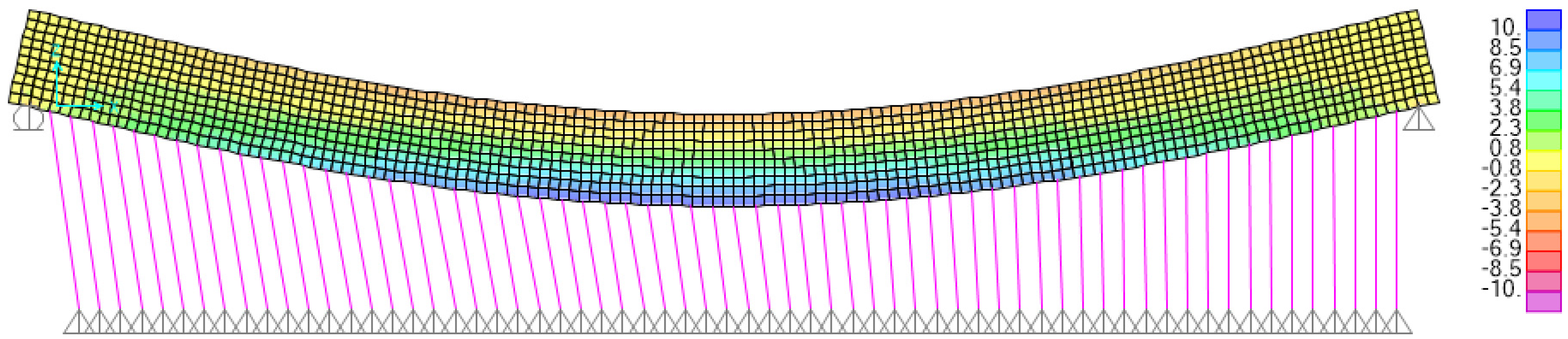
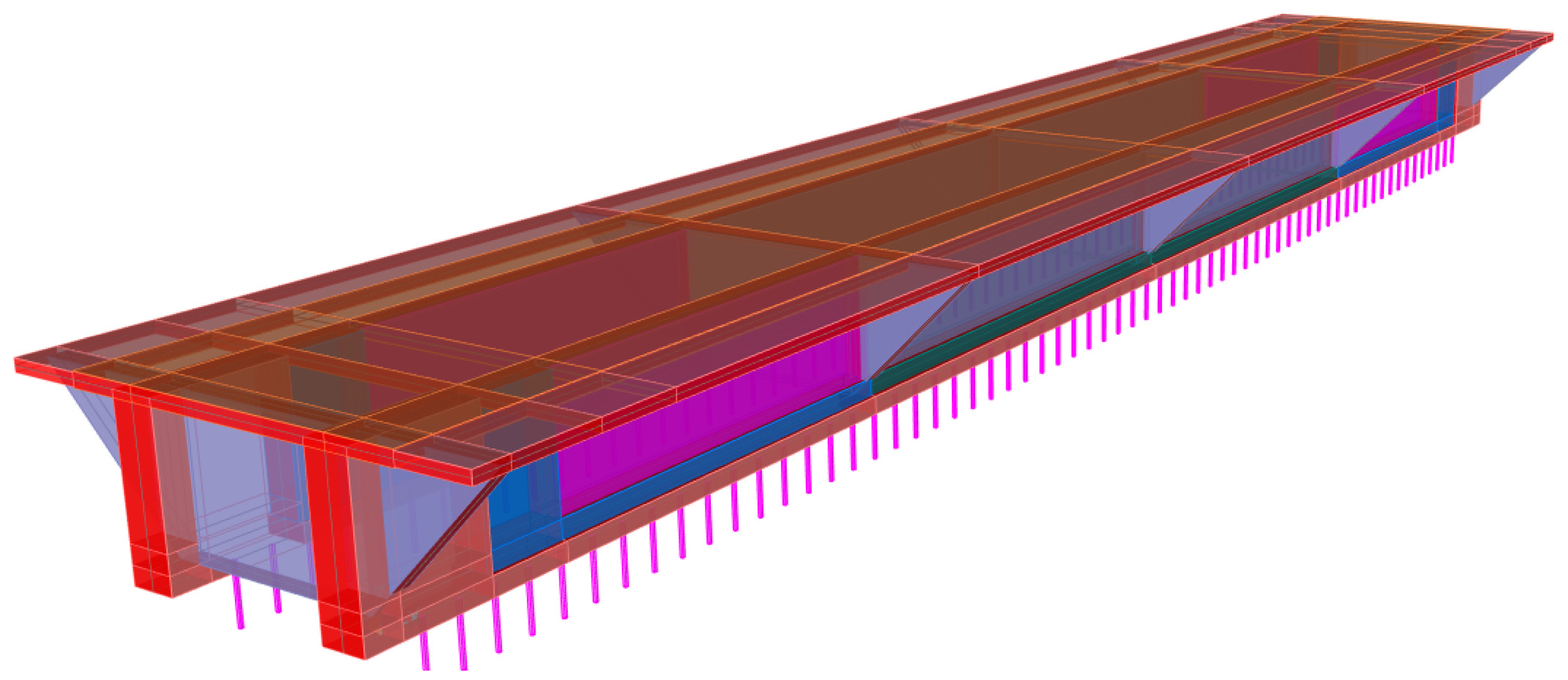
6. Numerical Simulations
7. Discussion
8. Conclusions
Author Contributions
Funding
Acknowledgments
Conflicts of Interest
References
- Cao, R.; El-Tawil, S.; Agrawal, A.K. Miami Pedestrian Bridge Collapse: Computational Forensic Analysis. J. Bridge Eng. 2020, 25, 04019134. [Google Scholar] [CrossRef]
- Tremblay, R.; Mitchell, D. Collapse during Construction of a Precast Girder Bridge. J. Perform. Constr. Facil. 2006, 20, 113–125. [Google Scholar] [CrossRef]
- Lewis, P.M.R.; Reynolds, K. Forensic Engineering: A Reappraisal of the Tay Bridge Disaster. Interdiscip. Sci. Rev. 2002, 27, 287–298. [Google Scholar] [CrossRef]
- Peng, W.; Tang, Z.; Wang, D.; Cao, X.; Dai, F.; Taciroglu, E. A Forensic Investigation of the Xiaoshan Ramp Bridge Collapse. Eng. Struct. 2020, 224, 111203. [Google Scholar] [CrossRef]
- Gautam, D.; Rupakhety, R. Empirical seismic vulnerability analysis of infrastructure systems in Nepal. Bull. Earthq. Eng. 2021, 19, 6113–6127. [Google Scholar] [CrossRef]
- Scattarreggia, N.; Salomone, R.; Moratti, M.; Malomo, D.; Pinho, R.; Calvi, G.M. Collapse Analysis of the Multi-Span Reinforced Concrete Arch Bridge of Caprigliola, Italy. Eng. Struct. 2022, 251, 113375. [Google Scholar] [CrossRef]
- Clemente, P. Monitoring and Evaluation of Bridges: Lessons from the Polcevera Viaduct Collapse in Italy. J. Civ. Struct. Health Monit. 2020, 10, 177–182. [Google Scholar] [CrossRef]
- Jiang, L.; Ye, J.; Zheng, H. Collapse Mechanism Analysis of the FIU Pedestrian Bridge Based on the Improved Structural Vulnerability Theory (ISVT). Eng. Fail. Anal. 2019, 104, 1064–1075. [Google Scholar] [CrossRef]
- Meng, Q.; Zhu, J.; Wang, T. Numerical prediction of long term deformation for prestressed concrete bridges under random heavy traffic loads. J. Bridge Eng. 2019, 24, 04019107. [Google Scholar] [CrossRef]
- Yang, J.; Guo, T.; Li, A. Experimental investigation on long-term behavior of prestressed concrete beams under coupled effect of sustained load and corrosion. Adv. Struct. Eng. 2020, 23, 2587–2596. [Google Scholar] [CrossRef]
- Bonopera, M.; Chang, K.C. Novel method for identifying residual prestress force in simply supported concrete girder-bridges. Adv. Struct. Eng. 2021, 24, 3238–3251. [Google Scholar] [CrossRef]
- Gautam, D.; Rupakhety, R.; Adhikari, R.; Baruwal, R.; Pokhrel, S.; Aryal, S. System identification of typical pre-code highway bridge in operation using heavy vehicle excitations. In Proceedings of the 17th World Conference on Earthquake Engineering, Sendai, Japan, 13–18 September 2020. [Google Scholar]
- Li, Y.; Dong, Y.; Frangopol, D.M.; Gautam, D. Long-term resilience and loss assessment of highway bridges under multiple natural hazards. Struct. Infrastruct. Eng. 2020, 16, 626–641. [Google Scholar] [CrossRef]
- Gautam, D. On seismic vulnerability of highway bridges in Nepal: 1988 Udaypur earthquake (MW 6.8) revisited. Soil Dyn. Earthq. Eng. 2017, 99, 168–171. [Google Scholar] [CrossRef]
- Gautam, D.; Rupakhety, R.; Adhikari, R. Empirical fragility functions for Nepali highway bridges affected by the 2015 Gorkha earthquake. Soil Dyn. Earthq. Eng. 2019, 126, 105778. [Google Scholar] [CrossRef]
- Thapa, S.; Shrestha, Y.; Gautam, D. Seismic fragility analysis of RC bridges in high seismic regions under horizontal and simultaneous horizontal and vertical excitations. Structures 2022, 37, 284–294. [Google Scholar] [CrossRef]
- Forcellini, D. A new methodology to assess indirect losses in bridges subjected to multiple hazards. Innov. Infrastruct. Solut. 2019, 4, 10. [Google Scholar] [CrossRef]
- Forcellini, D. Resilience-based methodology to assess soil structure interaction on a benchmark bridge. Infrastructures 2020, 5, 90. [Google Scholar] [CrossRef]
- Forcellini, D.; Walsh, K.Q. Seismic resilience for recovery investments of bridges methodology. In Proceedings of the Institution of Civil Engineers—Bridge Engineering; Thomas Telford Ltd.: London, UK, 2021. [Google Scholar] [CrossRef]
- Forcellini, D. Fragility assessment of seismic isolated bridges with soil–structure interaction effects. In Proceedings of the Institution of Civil Engineers—Bridge Engineering; Thomas Telford Ltd.: London, UK, 2021. [Google Scholar] [CrossRef]
- Tsiavos, A.; Amrein, P.; Bender, N.; Stojadinovic, B. Compliance-based estimation of seismic collapse risk of an existing reinforced concrete frame building. Bull. Earthq. Eng. 2021, 19, 6027–6048. [Google Scholar] [CrossRef]
- Computers and Structures Inc. SAP 2000; CSI Inc.: Pomona, CA, USA, 2013. [Google Scholar]


Publisher’s Note: MDPI stays neutral with regard to jurisdictional claims in published maps and institutional affiliations. |
© 2022 by the authors. Licensee MDPI, Basel, Switzerland. This article is an open access article distributed under the terms and conditions of the Creative Commons Attribution (CC BY) license (https://creativecommons.org/licenses/by/4.0/).
Share and Cite
Adhikari, R.; Jha, P.; Bhatt, L.; Thapa, D.; Forcellini, D.; Gautam, D. Failure Investigation of under Construction Prestressed Concrete Bridge in Chitwan, Nepal. Infrastructures 2022, 7, 14. https://doi.org/10.3390/infrastructures7020014
Adhikari R, Jha P, Bhatt L, Thapa D, Forcellini D, Gautam D. Failure Investigation of under Construction Prestressed Concrete Bridge in Chitwan, Nepal. Infrastructures. 2022; 7(2):14. https://doi.org/10.3390/infrastructures7020014
Chicago/Turabian StyleAdhikari, Rabindra, Pratyush Jha, Lalit Bhatt, Dipesh Thapa, Davide Forcellini, and Dipendra Gautam. 2022. "Failure Investigation of under Construction Prestressed Concrete Bridge in Chitwan, Nepal" Infrastructures 7, no. 2: 14. https://doi.org/10.3390/infrastructures7020014