

Operational Modal Analysis as a Support for the Development of Digital Twin Models of Bridges

Department of Construction, Civil Engineering and Architecture (DICEA), Università Politecnica delle Marche, Via Brecce Bianche, 60131 Ancona, Italy
*
Author to whom correspondence should be addressed.
Infrastructures 2023, 8(2), 24; https://doi.org/10.3390/infrastructures8020024
Submission received: 9 January 2023
/
Revised: 31 January 2023
/
Accepted: 2 February 2023
/
Published: 5 February 2023
(This article belongs to the Topic Development of Monitoring, Analysis and Maintenance Technics of Infrastructures)
Abstract
:Many transportation infrastructures all around the world are facing new challenges in terms of ageing and loss of performance. The infrastructural asset managers are required to perform scrupulous control of the health condition of the infrastructures over time and to execute the required maintenance works. In this context, digital twin models of the infrastructures should have a key role to simplify and speed up the procedures for proper maintenance. This paper discusses the advantages of developing digital twin models for the management of infrastructures, with a focus on bridges. In particular, the role of dynamic tests performed on bridges for the development of digital twin models is addressed, paying attention to test procedures and requirements. Issues such as the quality of instrumentation, the numerosity, and layout of sensors, and the acquisition and post-processing procedures are addressed through applications to two real bridge case studies. Both infrastructures are multi-span pre-stressed RC bridges that were dynamically tested after the restoration and seismic upgrading works. Results of ambient vibration tests and operational modal analyses are described, providing an idea of dynamic test requirements, as well as their use within the framework of the digital twin model creation.
1. Introduction
In many countries all around the world, transportation infrastructures are facing new challenges in terms of ageing and loss of performance, from both a structural and functional perspective [1]. Often, long-span bridges have a relatively good system for monitoring and maintenance [2], while short- and medium-span ones lack an information management system to accumulate the necessary data for monitoring and health assessment [3]. It is known that, without any appropriate measures for monitoring and maintenance, the deterioration of a bridge can lead to a loss of its functionality and even structural failure. In just the last decade, around 60 bridge failures occurred worldwide, followed by an equally large number of fatalities [1,4,5]. Among these failures, a striking example was the sudden and deadly collapse of the Morandi Bridge in Genova (Italy) in 2018, which killed 43 people [6]. For these reasons, bridges require proper management by the administering entities, which foresee a scrupulous control of the health condition of the structure over time, as well as the execution of the required works for good maintenance. Moreover, most of the existing RC pre-stressed bridges worldwide are now reaching such an age, for which, the degradation phenomena may become a concern [7,8]. For example, in Italy, most of the existing RC bridges were built between the ‘60s and ‘80s and they need nowadays to be carefully controlled and, very often, restoration works aimed to increase their safety are necessary to extend their service life [9].
The general procedure for bridge maintenance is a close loop of interactive processes including inspecting, monitoring, and performing appropriate repair or rehabilitation works (also including seismic retrofitting), and then upgrading the feedback to the database [10,11,12,13,14,15]. A suitable bridge maintenance can be supported by the development of a Digital Twin Model (DTM) of the infrastructure that collects as much information as possible about its features (structural, geometrical, functional) and about its health condition [16,17]. A DTM helps engineers to develop a long-term strategy for the operation and management of bridges and supports the organization of preventive maintenance [18]. In other words, this tool allows infrastructure managers to monitor and optimize their asset stock and to make informed and data-based decisions in the context of day-by-day operative conditions and after extreme events [19]. Therefore, DTM is a way of digitalization for the infrastructure management process, with the main aim of gaining new frontiers in the field of civil engineering, namely the development of so-called smart infrastructures [20]. Recently, 14 European partners involved themselves in a project called “ASHVIN: Digitizing and transforming the European construction industry”, with the common goal of proposing a European-wide DTM standard [21], demonstrating the actuality and importance of the topic.
One of the main targets of DTM is that of supporting the transition from the common time-based maintenance approach to the more effective and cost-saving condition-based maintenance philosophy. According to Farrar and Worden [22], the key prerequisite of condition-based maintenance is the deployment of a sensing system on the infrastructural assets. This would be able to measure the response, notify the operator of the emergence of defects or damage, support the numerical analysis for safety assessment, and allow for corrective actions to be taken rapidly before the damage evolves into failure [23]. One of the most common and adopted sensing typologies are accelerometers (or velocimeters), which are positioned on a structure to dynamically control its properties [24,25,26,27,28]. Indeed, as well known, experimental identification of bridge modal properties supports engineers in gaining a better physical understanding of the dynamic behaviour of these types of structures and provides fundamental support for the validation of numerical models [29,30,31,32]. Furthermore, the monitoring of vibration modes over time has proved to be an excellent tool for the development of Structural Health Monitoring (SHM) systems since they are related to intrinsic properties of the structure (i.e., mass, stiffness, and damping) and, therefore, to possible damage on the structure [33,34,35,36]. However, other testing techniques are nowadays available as an alternative to the use of accelerometers for structural dynamic identification, e.g., optical methods using 3D Laser Vibrometry Systems [37], or using Digital Image Correlation [38], or even adopting high-performance cameras [39].
This paper deals with the use of dynamic tests on bridges to support the DTM creation for the development of condition-based maintenance. At first, the DTM concept is introduced and the benefits of adopting dynamic tests in this framework are addressed, providing suggestions about the test typologies and requirements to achieve high-quality outcomes. Suggested procedures and testing requirements are then examined with reference to two real existing bridges located in Italy, assumed as case studies. The bridges were subjected to restoration works that also allowed their seismic upgrading; so, dynamic tests are performed after these works and the results are described, as well as their contribution to the DTM creation of the bridges.
2. The Digital Twin Model Concept
The DTM can be defined as the digital replica or virtual counterpart of a real entity, which can be assets, processes, systems, or even services [40]. The digital twin technology was first used by the National Aeronautics and Space Administration (NASA) to mend, update, and monitor the Apollo 13 space station, which is a non-physically human-present space station. Engineers and astronauts use the DTM to simulate and remotely fix technical errors [41]. Recently, this technology has been transferred also to the civil engineering field, with applications in several structures and infrastructures, although the most common applications are mainly relevant to the development of a DTM for plants and equipment design and management within buildings [42].
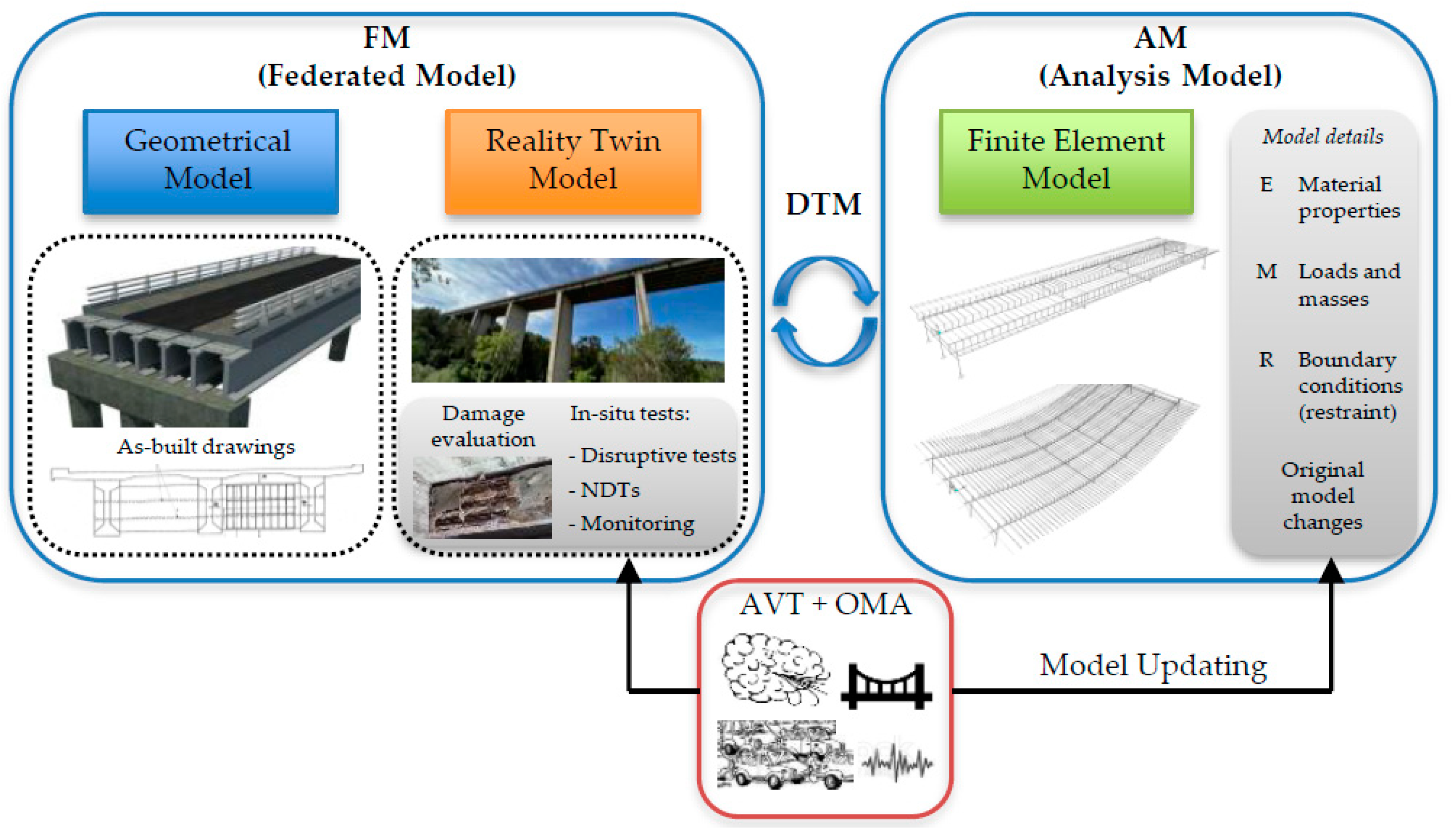
To develop a DTM of an infrastructure the following three tasks need to be performed: (i) the creation of a 3D geometrical model, (ii) the creation of the so-called Reality Twin Model (RTM), and (iii) the overlapping of these two models, creating the so-called Federated Model (FM) [17] (Figure 1). The 3D geometrical model is commonly based on the as-built documents of the existing bridge and represents a geometrical model of the real bridge, while the RTM represents the current status of the bridge (and for this reason, it is also called the ageing model) and can be achieved based on information collected from visual inspections, 3D scanning procedures, tests on the structural components, and monitoring systems [43,44]. The FM is an assembly of RTM with the geometrical model, and it can be used as the base for maintenance purposes. Furthermore, the environmental conditions (including temperature and humidity history), as well as loading history and monitoring data, are indispensable for predicting the consequent performance of the structural members. Obviously, these data can be collected through monitoring systems permanently installed on the infrastructure. In parallel with the FM, there is also an Analysis Model (AM) (sometimes called mechanical twin) that can be used within different finite element model commercial software to perform numerical analyses and, hence, to support the several safety assessments that could be required (verifications under different load conditions and damage levels, seismic assessments, etc.). FM and AM are the parallel aspects of one overall system (the DTM), which works derivatively, but simultaneously and interactively with each other [45].
As long as the bridge is ageing, the current status of the bridge continuously changes the structural input parameters of the AM. For instance, cracks, material degradation, and corrosion of steel elements are considered as reduction factors for the mechanical properties of concrete, reinforcement, and the prestressing tendons (strength and stiffness), but also for the boundary conditions (restraints); of course, the definition of these parameters is a challenge. To support this issue, destructive and Non-Destructive Tests (NDTs) can be performed, although the latter should be preferred because of their lower impact on the structural members. Many types of NDTs are nowadays performed on real applications, namely covermeter, georadar, tomography, ultrasonic, rebound hammer and X-ray tests that are used to investigate the condition of construction materials of the structural members.
Another type of NDT widely adopted nowadays is the dynamic testing, which foresee the use of sensors deployed on the structure (permanently or placed for a spot test) [46,47]. The DTM must be integrated with data achieved by sensors positioned on the structure, which effectively act as the nervous system of the real-life structure, providing information on its well-being (structural health) or concerns [48]. Among dynamic tests, the most common and adopted ones are the Ambient Vibration Tests (AVTs), which allow the identification of the dynamic behaviour of a structure during its operating conditions. These tests consist in measuring accelerations (or velocities) on the structure due to the so-called ambient noise, i.e., due to natural (wind, ground microtremors, sea waves, etc.) and anthropic (vehicle and railway traffic, industrial activities, etc.) excitation sources. Then, the dynamic behaviour of the structure is identified through the use of the Operational Modal Analysis (OMA) [49,50,51], which is an output-only identification technique that allows obtaining the modal parameters (frequencies, damping ratios and mode shapes) that describe the dynamic behaviour of the tested structure.
The modal parameters can be used in the development of a DTM for different purposes; as for the FM, data from AVTs are very useful in providing information about the real behaviour and health condition of the structure (at the time the test is performed), and they contribute to the formation of a database that characterizes the RTM, configuring itself as a sort of identity document of the structure at hand. If this identification is performed over time through the use of monitoring systems (continuously or with specific time intervals), it can provide valuable information about the health status of the structure and the possible damage occurring and/or evolution. Indeed, the dynamics of a structure (and, especially, its variation) can be configured as a sort of damage indicator since the presence of damage in a structural member in most cases leads to a reduction of its mechanical properties (in particular, the stiffness) and, consequently, in a variation of its dynamic response, or the dynamic response of the overall structure.
Considering the AM, the experimentally identified dynamic behaviour can be used to update the numerical model, which is modified and adjourned until its outcomes match well the experimental ones. This procedure is called model updating and can be divided into direct and indirect methods. The former foresees minor adjustments to the stiffness and mass matrices, without taking into account the change of physical parameters; the latter implies changing the model’s physical parameters until it accurately reproduces the data experimentally collected. Because of this procedure, the AM adopted to perform the different analyses is most representative of the structure and, therefore, the reliability of its results is enhanced. These modifications are commonly applied by adopting indirect methods and modifying the material mechanical properties (especially the material elastic moduli E), the loads and masses acting on the structure (M), and the restraint conditions (R). Sometimes, during the updating procedure, it is also necessary to modify the numerical model, adding some elements that were neglected at first, for example, some secondary structural components, non-structural elements, and even surrounding structures that provide a sort of restraint to the considered one.
To achieve the above benefits, dynamic tests must be performed with a high level of accuracy with reference to the instrumentation typology, numerosity and layout of sensors, length of recordings, data synchronization, and the quality of the signal post-processing, as well as the identification procedures (e.g., OMA techniques). In the sequel, the use of dynamic tests (more specifically, AVTs) in the framework of DTM development is addressed by considering two real bridges as case studies, to provide an idea of the testing requirements needed to provide detailed information for the DTM development.
3. Bridge Case Studies
3.1. Description of the Bridges
The two pre-stressed RC bridges considered as case studies are located in Central Italy. The original bridges had common construction materials and structural schemes (simply supported decks), and they were built approximatively in the same historical period. However, they have undergone different rehabilitation works (also adopting different strategies), and nowadays they are characterized by a different structural scheme and seismic protection devices. Therefore, the two bridges are selected to investigate the dynamics of both simply supported and continuous decks.
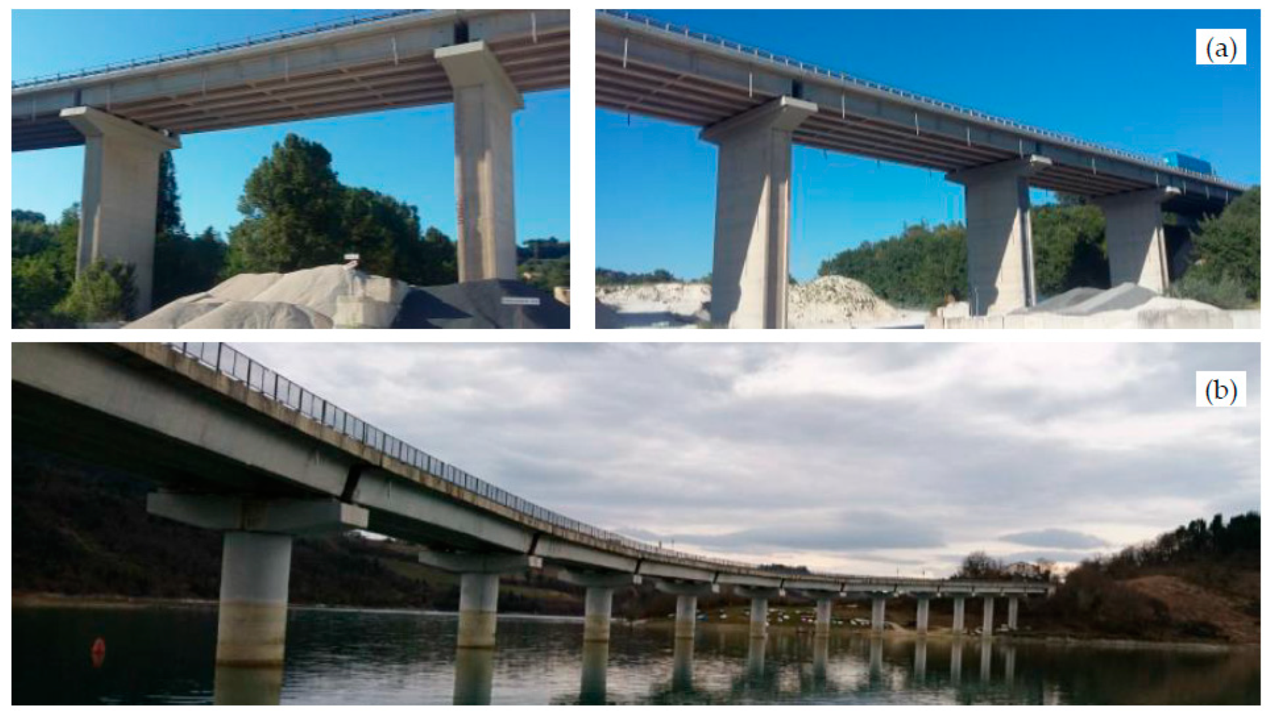
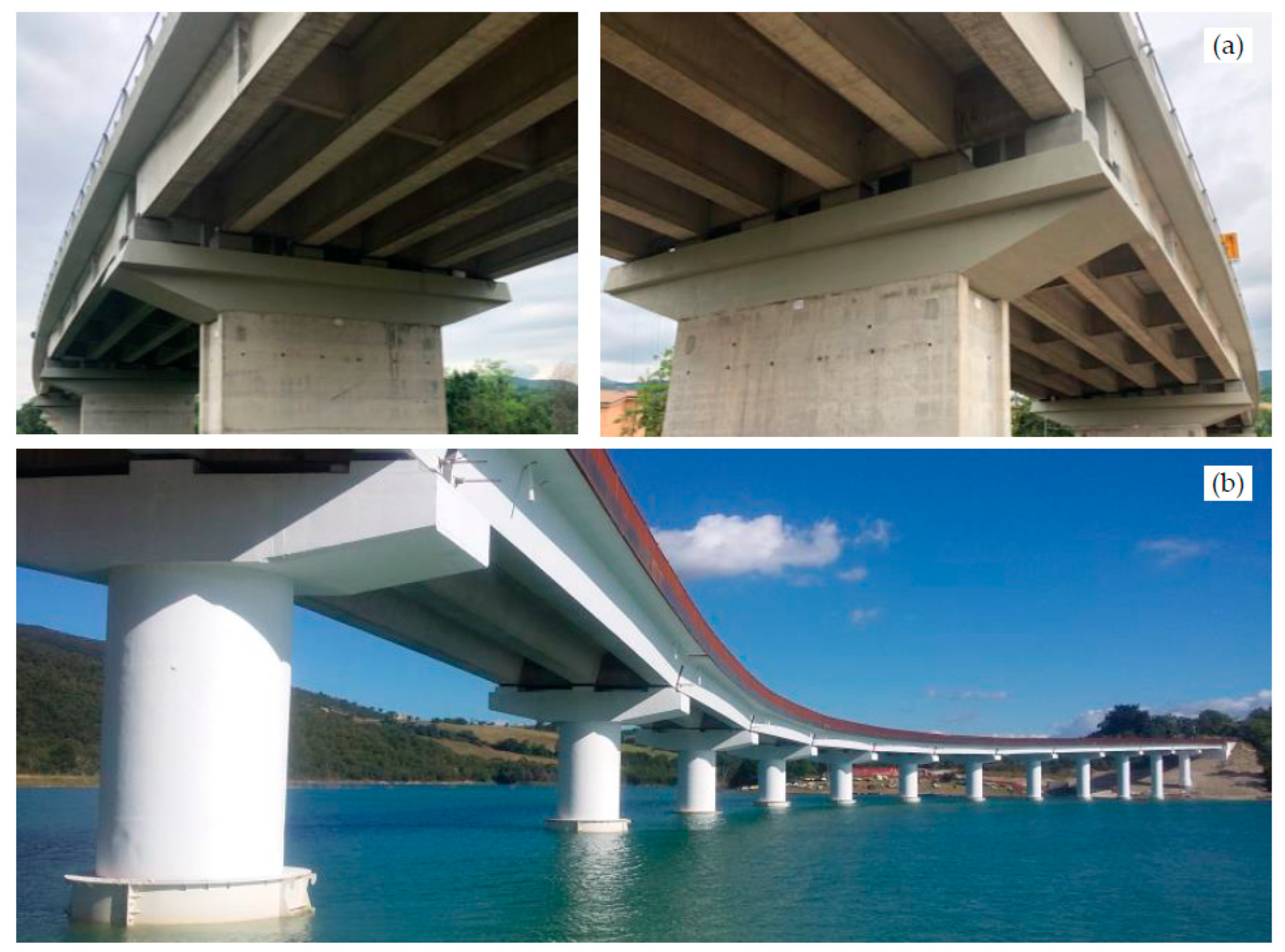
The first one, named Bridge 1 (B1 in Figure 2a), was built around the end of the ‘70s; it is 396 m long and consists of 11 simply supported spans approximately 36 m long and 16 m wide. The deck hosts 2 carriageways with a total of 4 traffic lanes and it is composed of six 2 m high I-shaped pre-stressed RC beams, connected by means of 5 pre-stressed RC transverse beams per span and by a 0.22 m thick RC slab. All supports are realized with 4 cm thick elastomeric neoprene bearings with dimensions of 0.6 × 0.8 m. The piers have a rectangular hollow cross-section with dimensions of 9 × 2.5 m, and variable heights ranging from 3.3 to 22.9 m. The pier caps have a wider solid cross-section with respect to the pier body, with 2 lateral cantilevers approximately 3.4 m long. The abutments have a box cross-section constituted by RC walls with a maximum thickness of about 1.25 m. Both piers and abutments are founded on 1 m diameter drilled piles. Altimetrically, the bridge presents a fairly constant gradient, while planimetrically it presents a slightly curved layout, starting from the mid-length to the western abutment.
The second bridge, called Bridge 2 (B2 in Figure 2b), was built at the beginning of the ‘90s for crossing an artificial lake originated by the presence of a dam built for electric power generation purposes. The bridge is 472 m long and it is composed of 14 spans (originally simply supported) about 31 m long and about 11 m wide. The deck hosts a single 8.6 m wide carriageway with 2 traffic lanes, and it is constituted by three 1.8 m high V-shaped pre-stressed RC box girders transversally spaced at 3.6 m. The girders are connected by means of 2 transverse beams per span, positioned over the piers, and by a 0.2 m thick RC slab. The 13 piers have a solid circular cross-section that is variable in height, with 2.6 m of diameter on the top and 4 m diameter at the bottom. Piers have also variable heights, ranging from about 9 to about 19 m. Pier caps have a solid cross-section with a trapezoidal shape, with plan dimensions of 9 × 3 m.
Both piers and abutments have shallow foundations consisting of square cross-section plinths with 1.8 m of height, except for one pier on the mid-length of the bridge that is founded on a plinth built over micropiles. The deck was originally supported on 84 conventional fixed and monodirectional or bi-directional Teflon sliding bearings, distributed, according to the bridge design, to allow the bridge movements due to thermal effects. The latter was combined with a passive seismic protective system, constituted by hysteretic devices. Altimetrically, the bridge has an important grade, especially in the northern part, and also an important curvilinear plane shape.
3.2. State of Conservation and Damage
The B1 and the B2 bridges are respectively more than 40 and 30 years old; thus, both structures started to present ageing degradation phenomena typical of RC structures subjected to weathering. Moreover, both of them were struck by the Central Italy earthquakes that occurred in 2016 and which produced some damage to both structures.
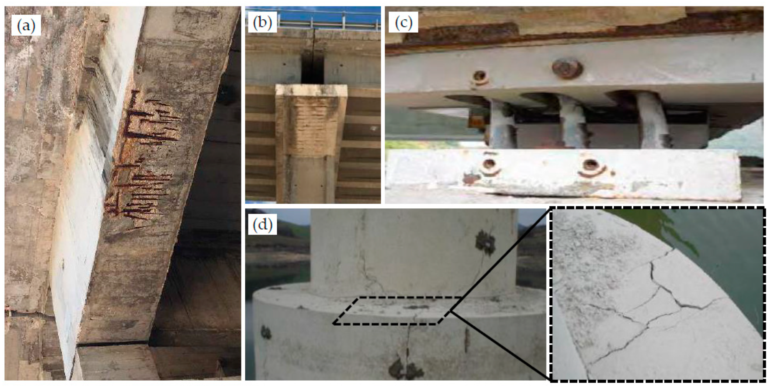
The main ageing phenomena of the B1 bridge were the pavement expansion joints degradation, which allowed water infiltration and dripping over the RC slabs, beams and pier caps, with consequences on the concrete integrity and the steel rebars corrosion. Also, the deck stormwater drainage system was compromised, so that the water percolated along the intrados of the cantilever slabs and on the external surfaces of the lateral beams, producing damage on both concrete and rebars, as discussed above. In particular, for one of the lateral beams (Figure 3a) of the western span, these degrading phenomena were so evident to require an appropriate retrofitting intervention. Furthermore, the seismic sequence that occurred in 2016 produced damage to the RC bearing supports that experienced local failure and the ejection of the concrete cover.
For what concerns the B2 bridge, one of the major concerns was due to the presence of a wide crack pattern along the shaft of one pier (Figure 3d), which was discovered for the first time in 1997. No sure causes have been found for this phenomenon, which was associated with defects in casting operations during construction, even if it continued to evolve until the execution of the retrofit works. Moreover, in some piers, the localized corrosion of steel rebars was detected, especially in that zones where the concrete cover was very thin. Another detected problem was the erroneous positioning of many support devices in almost half of the spans, which led to an erroneous and unexpected restraint system for the bridge that limited the deck deformations due to thermal effects and creep and shrinkage of concrete.
These errors also led to unexpected displacements of movable supports, with consequences on plastic deformations of some dissipative devices (Figure 3c), and on bending stresses on piers, not considered in the design phase. Seismically, the bridge did not suffer significant damage due to the 2016 earthquakes; nevertheless, the original seismic design was not compliant with the regulations provided by modern codes.
3.3. Sesimic Retrofit Works
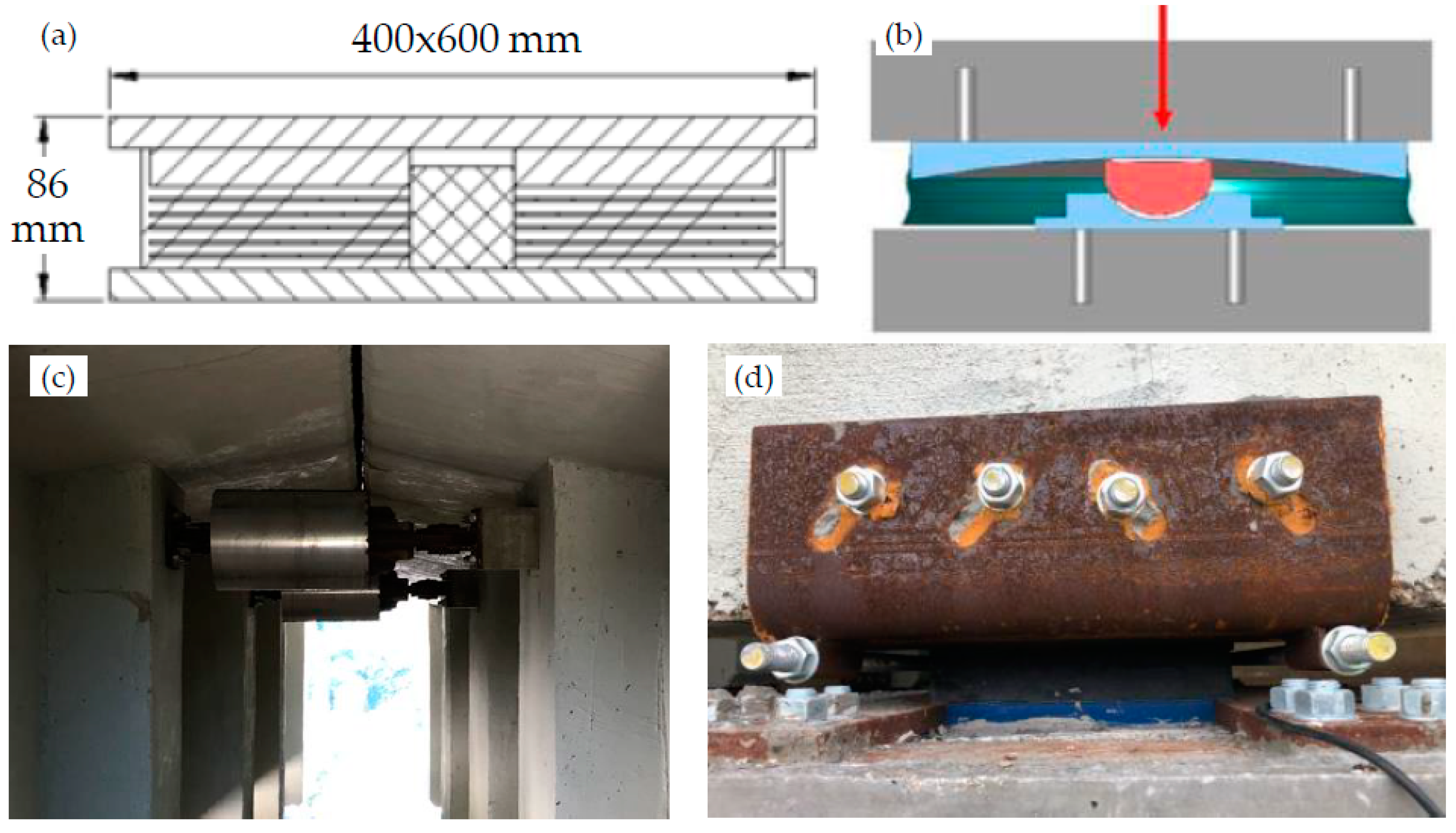
After the seismic sequence of 2016, both bridges were retrofitted with the target to upgrade their seismic performance and to restore those parts of the structural members that suffered damage during the years. The seismic retrofit foresaw a main intervention that was common for both structures and that consisted of the replacement of the support devices with new seismic isolators. As well known, the seismic isolation of the deck has many advantages, such as the bridge response regularization, along with the drastic reduction of the seismic (horizontal) forces acting on the top of piers as a consequence of the period elongation. Moreover, isolators enhance the damping capacity of the structure. For the B1 bridge, 8.6 cm thick Lead Rubber Bearings (LRBs) with plan dimensions of 40 × 60 cm (Figure 4a) were positioned at each support of all the deck beams, whilst for the B2 bridge, Single Friction Pendulum Surface (SFPS) bearings were adopted (Figure 4b). It was not easy to carry out these interventions as they required controlled deck lifting using many hydraulic jacks, in some cases also performing the uplift procedures with the bridge open to traffic. Furthermore, in the B1 bridge, seismic dampers were mounted between the heads of all beams facing each other over the same pier (Figure 4c), to reduce span movements under horizontal actions and to avoid seismic pounding. In the B2 bridge, also the jacketing of piers was performed to increase their bearing capacity to vertical loads and also their bending resistance under horizontal actions. The latter was carried out by enlarging the bottom part of the piers by means of a 30 cm thick RC concrete layer, while in the top part of the piers, a carbon fiber strengthening layer was adopted. Finally, in the B2 bridge, the simply supported spans were connected to each other by means of a transverse RC beam built in correspondence with each pier, to realize a continuous deck.
In addition to the aforementioned seismic retrofit works, both bridges were subjected to other structural retrofit interventions. The deteriorated concrete parts of the structural elements were repaired, through preliminary sand-blasting, passivation of steel rebars and reconstruction of the concrete cover with fiber-reinforced concrete.
Besides, for the B1 bridge, the slab joints between spans were retrofitted and the expansion joints on the pavement were substituted, whereas joints were filled with RC concrete for the B2 one, where also the lateral barriers were substituted with new ones both for safety and aesthetical reasons. Pictures relevant to the bridges after the retrofitting works are reported in Figure 5.
4. AVTs and OMAs for the Digital Twin Model of the Bridges
4.1. AVT Setup and Protocols
In this Section, details about dynamic tests performed on both bridges are provided. These may offer an example, from which guidance can be drawn, about the level of accuracy of test setup and protocols required to achieve results good enough to be used for DTM purposes.
The AVTs were performed on both bridges after the execution of the seismic retrofitting works. This dynamic test typology is widely adopted as NDT in the civil engineering field since it allows the dynamic characterization of structures and infrastructures through the acceleration recordings produced by the so-called ambient noise; the latter has both natural and man-made causes and almost always can excite the entire structure at hand. For both bridges, the ambient noise was due to microtremors and moderate wind; only for the B1 bridge, a man-made excitation was also present because the bridge remained partially open to traffic during the tests. Contrarily, the B2 bridge was completely closed to traffic during AVTs. Bridges were tested during the summer: the B1 bridge on 24 July, with a daily air temperature varying between 26 and 34 °C; the B2 bridge on 26 June, with a daily temperature ranging between 21 and 25 °C. In both cases, the values of resonance frequencies obtained from different measurement configurations performed during the test day proved to be remarkably constant, demonstrating that the daily temperature variation has little influence on the dynamics of these bridges.
The adopted instrumentation consisted of 10 low-noise uniaxial piezoelectric accelerometers (PCB 393B31, with high sensibility and high signal-to-noise ratio) positioned on the deck and connected by means of coaxial cables to 4-channels acquisition modules (NI 9234) mounted on an 8-slot USB chassis (NI cDAQ-9178). A laptop equipped with dedicated software (developed in the LabVIEW environment) was adopted for data acquisition and control. Due to the limited number of sensors and the considerable lengths of the bridges, many sensor configurations were employed, hence performing many AVTs for each bridge. Some sensors, called reference sensors, were left in the same position during the experimental campaign to have benchmark results for all the tests, necessary for obtaining the global mode shapes, as it will be better addressed in the sequel. For each AVT, at least half-an-hour-long acceleration time histories were recorded with a sampling frequency of 2048 Hz.
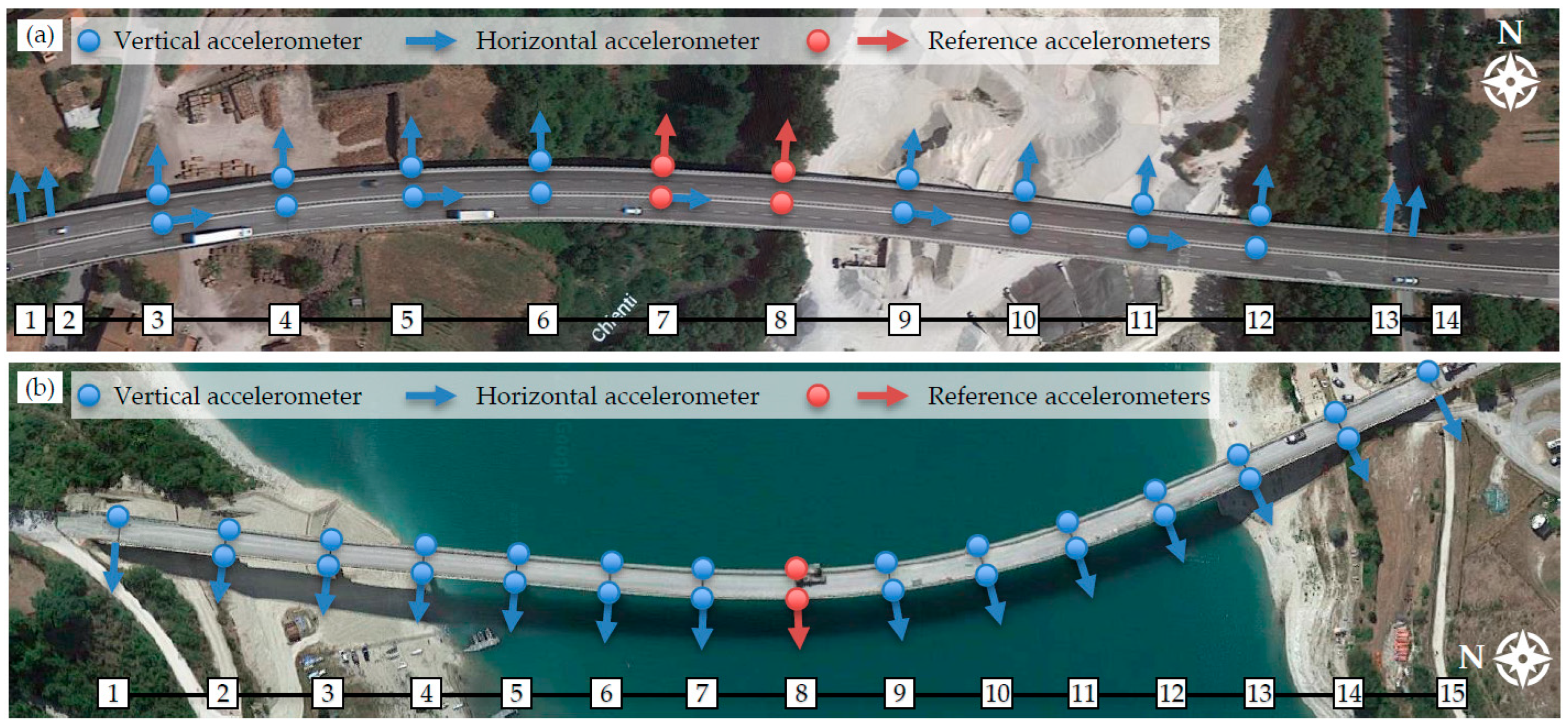
As for the B1 bridge, 6 non-contemporary configurations were adopted by positioning 6 reference sensors nearby the mid-length of the bridge (Figure 6a). Sensors were positioned with their measurement direction in transverse, longitudinal and vertical directions with respect to the bridge development, to identify transverse, longitudinal and vertical vibration modes. The latter can be divided into bending and torsional modes of the deck; thus, to also identify the torsional modes, the vertical sensors were transversally positioned in two different locations, i.e., on the lateral kerb and in the middle of the deck width (because the bridge was partially opened to traffic). In correspondence with the abutments, 2 transverse sensors were positioned as well, 1 on the bridge and 1 on the roadway embankment, to investigate possible abutment transverse movements and their influence on the modal displacements of the whole structure.
Also for the B2 bridge the sensor layouts were similar: in this case, 8 sensor configurations were adopted and only 3 reference sensors were used, located at the mid-length of the bridge (Figure 6b). The 2 vertical sensors for each measuring station were positioned on the two lateral kerbs since the bridge was closed to traffic. In this case, longitudinal sensors were not positioned because, for this bridge typology, the longitudinal modal displacements of the deck are less significant than the transverse and vertical ones, even almost negligible. For both case studies, the transverse sensors were located in correspondence with the piers, because the transverse deformability of the structures relies on the flexural stiffness of the vertical members, and possible rocking motions at the foundation level. Only 1 sensor for each pier was employed because, for the B2 bridge, the deck is continuous, whereas for the B1 one a preliminary investigation was performed to verify that movements on the right and left side of the deck joint were almost identical.
4.2. OMAs and Experimental Dynamic Behaviour of the Bridges
The recorded signals are treated adopting common signal pre-processing procedures, consisting of correction of signal spurious trends using a 3rd-degree polynomial function, low pass filtering of the analogic signal above the Nyquist frequency with a cut-off frequency of 25.6 Hz (to eliminate the contribution of high frequencies and avoid aliasing phenomena), and down-sampling of the signal to 51.2 Hz to limit the amount of data to be managed. Then, the experimental modal parameters of the bridges are identified through the OMA procedure.
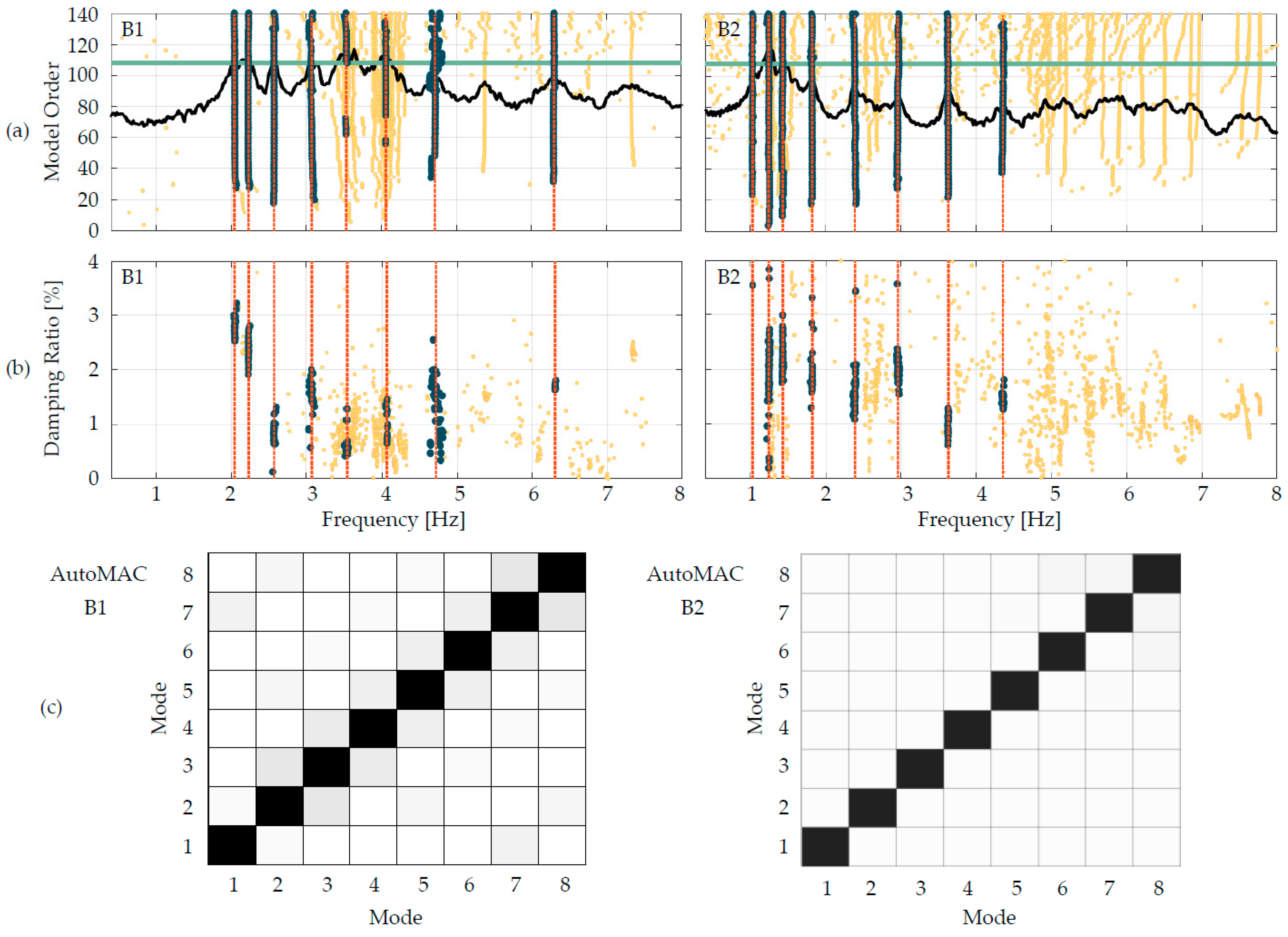
For example, in Figure 7a, a stabilization diagram for a single AVT for each bridge is depicted, together with the relevant frequency-damping ratio diagram. Moreover, the 1st Singular Value (SV) is also reported for completeness and to highlight the peaks that characterize each vibration mode of the bridges. During the identification procedures, a vibration mode is assumed stable (dark dot columns in Figure 7) if the frequency variation between two subsequent model orders is less than 1%, the damping ratio variation is less than 2% and the Modal Assurance Criterion (MAC) is greater than 0.98. The selection of the modes is performed with the support of an agglomerative hierarchical clustering algorithm, implemented within the adopted software. This provides valuable support in cases where the identifications furnish very close point columns.
As can be observed from Figure 7 and Figure 8 very stable vibration modes are identified for both bridges and the relevant frequencies and damping ratios are listed in Table 1 and Table 2. Moreover, from the off-diagonal MAC values of the AutoMAC matrices reported in Figure 7c (very low since the boxes are almost white), it is also evident that all modes are orthogonal to each other, proving that they are real modes and also assessing the correctness of the adopted sensor layouts, which made it possible to avoid the so-called spatial aliasing phenomena [49]. A single identification is performed for each AVT, namely for each sensor configuration that was adopted during the in-situ tests. Consequently, 6 and 8 identification procedures are performed for the B1 and the B2 bridges, respectively. Resulting frequencies and damping ratios are calculated as the mean of the values obtained for each identification, whilst to merge the results and to obtain global mode shapes, the Post Separate Estimation Re-scaling (PoSER) post-processing procedure is adopted [49]. This consists in scaling the identified modal displacements obtained from each dynamic test based on the modal displacements of the reference sensors, which are common to all the acquisitions during in-situ dynamic tests.
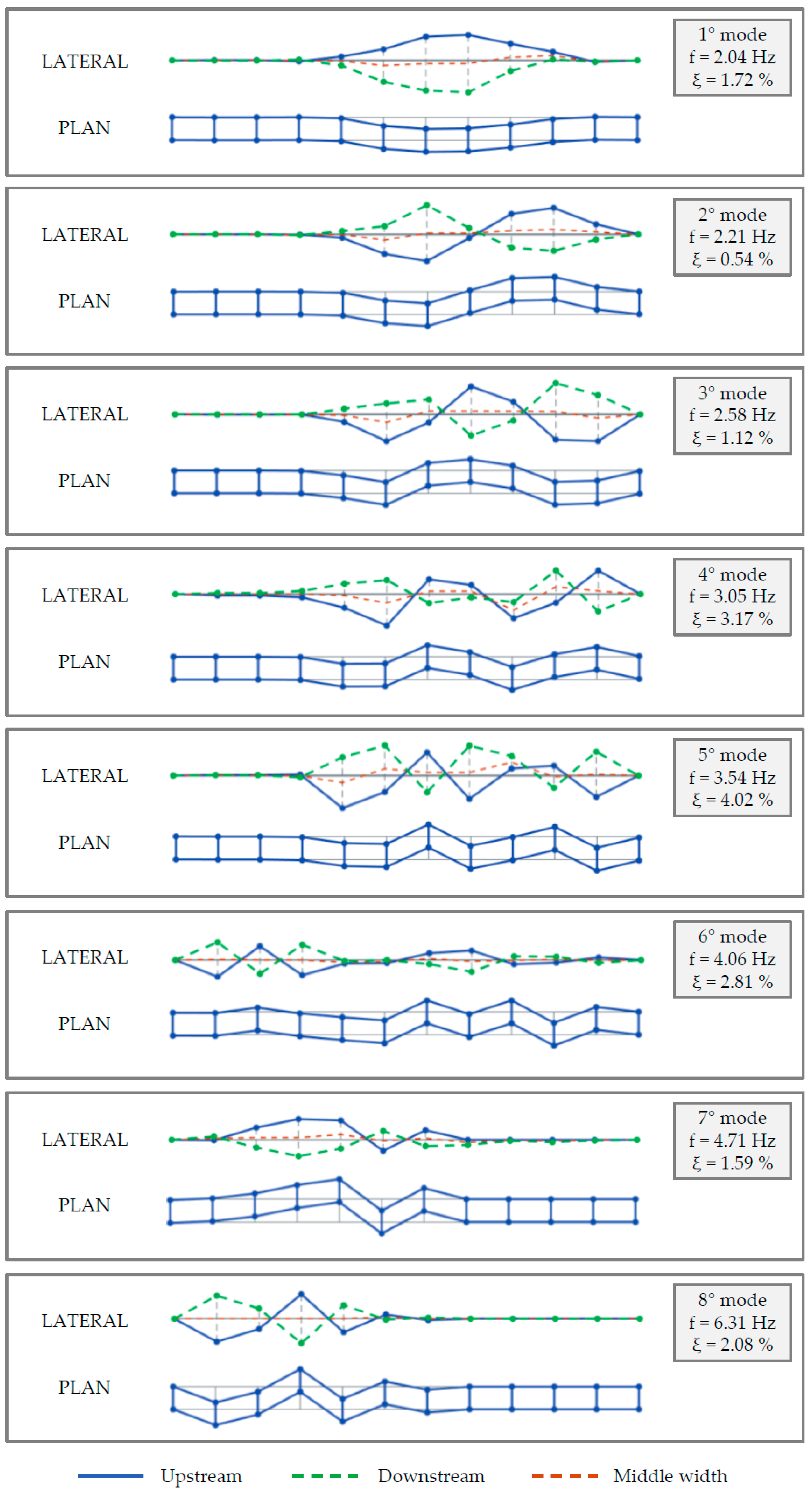
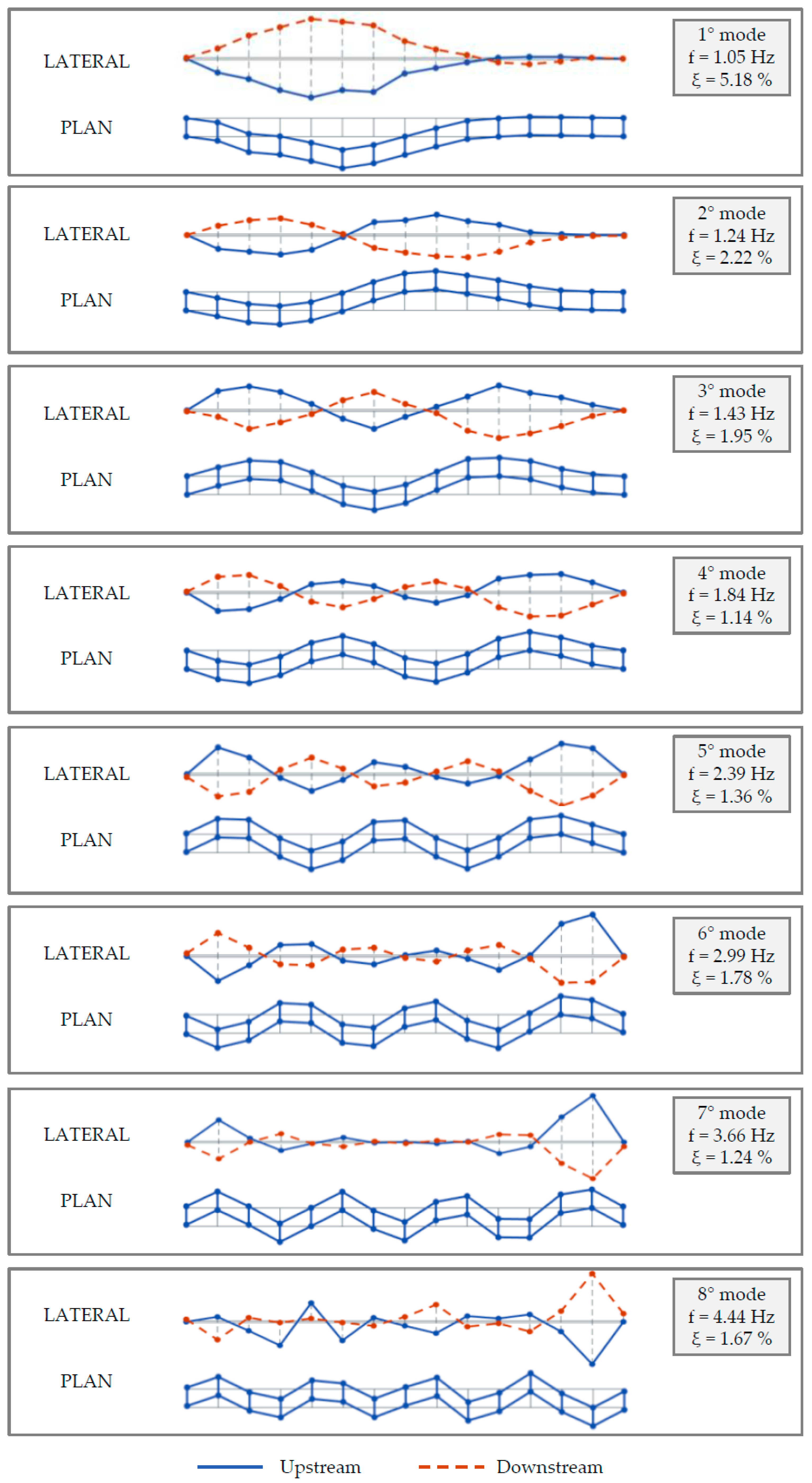
The global mode shapes obtained at the end of the merging procedure are illustrated in Figure 8 and Figure 9. They are drawn neglecting the longitudinal modal displacements (for the B1 bridge longitudinal modal displacements are negligible compared with the transverse and vertical ones, while for the B2 bridge, they were not measured) and assuming as the simplifying hypothesis that on the transverse direction, the deck is axially non-deformable, which implies that on a predetermined deck transverse section the upstream and downstream modal displacements are assumed to be equal. It is worth observing that for the B1 bridge the lateral views of the mode shapes are drawn with three lines instead of two; this is due to the fact that the downstream profile (the green one) has been reconstructed supposing the deck infinitely stiff for transverse bending since it was possible to measure only the upstream and middle width profiles. It is worth observing that, although the two bridges are quite different from each other (and, in particular, after the retrofitting works), the first vibration modes are very similar in terms of mode typology/shape and mode order of appearance.
Only for the B2 bridge, the same dynamic tests described above were also performed before the retrofitting works; therefore, a comparison between the frequency values identified before and after the works can be performed and, considering the fundamental mode, the frequency moves from 0.94 to 1.05 Hz, namely the seismic upgrading produced an increment of the 1st frequency of about 12%, as expected since the spans were linked together, as well as the piers were stiffened.
The obtained modal parameters for both bridges are characterized by a very high level of accuracy and quality (proved by the very clean stabilization diagrams and the almost diagonal AutoMAC matrices), demonstrating the right choices in the adopted test configurations and protocols. These good results can be very useful for the development of the DTMs of both bridges. Moreover, the high number of measurement points over the deck led to identifying a high number of modes with very refined mode shapes; the latter was revealed to be of paramount importance for the complete and trustworthy identification of the mode typologies. In fact, differently from common buildings, bridge dynamics (and, in particular, that for the longer ones) could be characterized by articulated modal shapes that, in the case of few sensors, could be misinterpreted, leading to errors in the dynamic identification (occurring in problems related to the spatial aliasing phenomenon).
4.3. The Use of the Bridge Dynamic Behaviour in the Digital Twin Model Development
The experimentally identified dynamic behaviour of the bridge case studies can be considered an important step in the development of the DTM of each bridge. In this section, ideas of possible uses are discussed, giving the reader a comprehensive view of strategies that can be developed, and the great advantages that may arise from their use.
Focusing the attention on the FM part, the performed AVTs can be considered as NDTs that increase the knowledge of the real behaviour of both infrastructures. Indeed, being the dynamic tests performed after the retrofitting works, they provided information about the bridge’s dynamic behaviour after the works, so in their new retrofitted and healthy state. This information may be used as a benchmark for bridge control during this time, since it characterizes the healthy status of the bridges in their RTM. This fundamental data can be used for future comparisons after new AVTs and OMAs to assess the health status of the infrastructures, and also considered as benchmark information to set up thresholds in case of continuous monitoring. In fact, it should be advantageous for the owners of the bridges to install a dynamic monitoring system, consisting of several accelerometers placed over the decks.
Thanks to the acceleration measurements, the dynamic behaviour of the infrastructures can be identified at more or less frequent time intervals, adopting, for instance, automatic algorithms for the dynamic identification (the so-called AutoOMA procedures [52,53]); this dynamic behaviour should be controlled over time, for example with the support of time-frequency graphs. If the monitored frequency values drop below pre-determined thresholds (fixed based on the experimentally identified dynamic behaviour previously discussed), alerts can be sent to the facility managers and countermeasures can be promptly taken, therefore increasing the safety usage of the bridges. In this context, the software used to manage the infrastructures by public entities could be enhanced with new functions that allow the storage and interpretation of field dynamic test results, and/or new software combining management functions with experimental data analysis functions could be developed.
In the context of the AM, the experimental dynamic behaviour of the bridges can be used as a benchmark for the updating of numerical models. This is done by modifying mechanical parameters, masses and even the geometry of the models as long as the numerical dynamic behaviour of both bridges matches well the experimental one (in terms of modal parameters). Again, the availability of calibrated models is very important for many purposes; because they represent the bridges in their real and actual state, calibrated models can support the design of the monitoring systems discussed above, for example implementing numerical analyses that allow the individuation of the optimal number and position of sensors to identify as much vibration modes as possible (adopting optimal sensor placement procedures [54]). In addition, the DTM, calibrated on the real bridge behaviours, can be used to numerically investigate possible and reasonable damage scenarios in which damage (and even failure) of structural members, as well as effects of environmental disasters (floods, landslides, pier scours, etc.), are considered and their effects on the structural performance are investigated. Moreover, during these damage simulations, changes in the dynamic behaviour are investigated as well, to achieve thresholds that can be implemented in the dynamic monitoring systems developed for the bridge health monitoring.
5. Conclusions
This paper discussed the use of ambient vibration tests and operational modal analyses as a support for the creation of DTM of infrastructures, with a particular focus on bridges. The concept of DTM in infrastructural asset management has been introduced and well explained at the beginning of the paper, where also the benefits relevant to the use of dynamic in-situ tests for supporting the DTM creation and updating our in-depth discussion. Then, the applications and advantages of these dynamic tests in the DTM framework are treated, focusing on two real bridges considered as case studies. The bridges are multi-span pre-stressed RC bridges built in Central Italy and were the object of restoration works due to ageing degradation and seismic upgrading. The bridges have been widely described, and the ambient vibration tests performed on both of them have been extensively addressed, providing useful and detailed results. Then, ideas about the use of these results in the development of the DTM of bridges have been provided.
The advantages of the use of dynamic test outcomes within the DTM framework have been comprehensively treated and it has also been proven that they interact with many parts and in many phases of the DTM development. Considering the part of the DTM in which the real structure is schematized and controlled (federated model), ambient vibration tests and operational modal analyses can be used to provide information about the actual state of the infrastructure, offering information about the real dynamic behaviour of the facility at the time when the tests are performed. This useful information can be compared with other measurements during the time to individuate possible changes and, as in the case of the bridge case studies, if the tests are performed on bridges in a good state of conservation (healthy state), the results can be considered as benchmarks for future comparisons, also when permanent dynamic monitoring is installed. In the numerical counterpart of the DTM (the analysis model), dynamic test outcomes can support the updating and calibration of the numerical model of the infrastructures. The calibrated numerical model is fundamental for many purposes, along with supporting the design of monitoring systems (adopting, for example, optimal sensor placement analyses), as well as performing damage scenarios analyses that provide fundamental data for the management of the monitoring and maintenance activities.
Proper development of a DTM for a strategic asset (as a bridge) should be complemented by the development of ambient vibration tests and operational modal analyses because of their many advantages and utility. These types of tests are very easy and fast to perform and, usually, they do not require the roadway closing to traffic. So, the infrastructure administrators should prescribe also these tests when non-destructive tests are required to implement the knowledge about the infrastructure, and, in particular, when these tests are finalized for the development of the safety assessment. A great amount of dynamic tests performed on an equally large number of infrastructures is the first step toward information-rich databases that can support infrastructure management and monitoring and toward a future made of smart infrastructures.
Author Contributions
Conceptualization, V.N., S.C. and F.G.; Methodology, V.N., S.C. and F.G.; Software, V.N., R.M. and F.G.; Formal Analysis, V.N. and R.M.; Investigation, V.N. and F.G.; Data curation, V.N. and R.M.; Writing—original draft preparation, V.N. and R.M.; Writing—review and editing, S.C. and F.G.; Visualization, V.N. and R.M.; Supervision, F.G.; Project administration, F.G. All authors have read and agreed to the published version of the manuscript.
Funding
This research received no external funding.
Institutional Review Board Statement
Not applicable.
Informed Consent Statement
Not applicable.
Data Availability Statement
Not applicable.
Acknowledgments
This work is developed within the research project PROTECT: maPping the seismic Risk Of straTEgiC consTructions (2019–2022). The project received funding from the Fondazione Cariverona and Fondazione Cassa di Risparmio di Padova e Rovigo, under grant agreement ID 10758 and Cod. SIME 2018.0853.2019.
Conflicts of Interest
The authors declare no conflict of interest.
References
- ASCE. ASCE Report Card from America’s Infrastructure 2021—A Comprehensive Assessment of America’s Infrastructure Executive Summary; ASCE: New York, NY, USA, 2021. [Google Scholar]
- Dang, N.S.; Shim, C.S. BIM authoring for an image-based bridge maintenance system of existing cable-supported bridges. IOP Conf. Ser. Earth Environ. Sci. 2018, 143, 012032. [Google Scholar] [CrossRef]
- Parviainen, P.; Tihinen, M.; Kääriäinen, J.; Teppola, S. Tackling the digitalization challenge: How to benefit from digitalization in practice. Int. J. Inf. Syst. Proj. Manag. 2017, 5, 63–77. [Google Scholar] [CrossRef]
- Jithiya, K.K.; Pandikkadavath, M.S.; Nagarajan, P.; Mangalathu, S. Influence of Span Length on Seismic Mainshock—Aftershock Response of RC Bridges Pre-Exposed to Scouring. Lect. Notes Civ. Eng. 2023, 269, 635–647. [Google Scholar] [CrossRef]
- Ferro, G.A.; Restuccia, L.; Falliano, D.; Devitofranceschi, A.; Gemelli, A. Collapse of Existing Bridges: From the Lesson of La Reale Viaduct to the Definition of a Partial Safety Coefficient of Variable Traffic Loads. Eng. Struct. 2022, 148, 04022181. [Google Scholar] [CrossRef]
- Calvi, G.M.; Moratti, M.; Scattarreggia, N.; Özsaraç, V.; Pinho, R. Numerical Investigations on the Collapse of the Morandi Bridge. Springer Tracts on Transportation and Traffic; Springer: Cham, Switzerland, 2021; Volume 17, pp. 3–18. [Google Scholar] [CrossRef]
- Salamone, S.; Bartoli, I.; Phillips, R.; Nucera, C.; di Scalea, F.L. Health Monitoring of Prestressing Tendons in Posttensioned Concrete Bridges. Transp. Res. Rec. J. Transp. Res. Board 2011, 2220, 21–27. [Google Scholar] [CrossRef]
- Bonopera, M.; Chang, K.; Chen, C.; Sung, Y.; Tullini, N. Experimental study on the fundamental frequency of prestressed concrete bridge beams with parabolic unbonded tendons. J. Sound Vib. 2019, 455, 150–160. [Google Scholar] [CrossRef]
- Tonelli, D.; Rossi, F.; Brighenti, F.; Verzobio, A.; Bonelli, A.; Zonta, D. Prestressed concrete bridge tested to failure: The Alveo Vecchio viaduct case study. J. Civ. Struct. Health Monit. 2022, 1–27. [Google Scholar] [CrossRef]
- Housner, G.W.; Bergman, L.A.; Caughey, T.K.; Chassiakos, A.G.; Claus, R.O.; Masri, S.F.; Skelton, R.E.; Soong, T.T.; Spencer, B.F.; Yao, J.T.P. Structural Control: Past, Present, and Future. J. Eng. Mech. 1997, 123, 897–971. [Google Scholar] [CrossRef]
- Giordano, P.F.; Limongelli, M.P. The value of structural health monitoring in seismic emergency management of bridges. Struct. Infrastruct. Eng. 2020, 18, 537–553. [Google Scholar] [CrossRef]
- Torti, M.; Venanzi, I.; Laflamme, S.; Ubertini, F. Life-cycle management cost analysis of transportation bridges equipped with seismic structural health monitoring systems. Struct. Health Monit. 2022, 21, 100–117. [Google Scholar] [CrossRef]
- Rainieri, C.; Notarangelo, M.A.; Fabbrocino, G. Experiences of Dynamic Identification and Monitoring of Bridges in Serviceability Conditions and after Hazardous Events. Infrastructures 2020, 5, 86. [Google Scholar] [CrossRef]
- Faroz, S.A.; Coelho, M.; Santos, C.; Matos, J. A proactive time to first repair for coastal rc bridge with prescriptive durability provisions. Indian Concr. J. 2021, 95, 58–64. [Google Scholar]
- Gaile, L.; Pakrastins, L.; Ratnika, L. Structural health monitoring by merging dynamic response data. Mag. Civ. Eng. 2022, 111, 11111. [Google Scholar] [CrossRef]
- Bado, M.F.; Tonelli, D.; Poli, F.; Zonta, D.; Casas, J.R. Digital Twin for Civil Engineering Systems: An Exploratory Review for Distributed Sensing Updating. Sensors 2022, 22, 3168. [Google Scholar] [CrossRef]
- Shim, C.-S.; Dang, N.-S.; Lon, S.; Jeon, C.-H. Development of a bridge maintenance system for prestressed concrete bridges using 3D digital twin model. Struct. Infrastruct. Eng. 2019, 15, 1319–1332. [Google Scholar] [CrossRef]
- Bolton, A.; Butler, L.; Dabson, I.; Enzer, M.; Evans, M.; Fenemore, T.; Harradence, F.; Keaney, E.; Kemp, A.; Luck, A. Gemini Principles; Centre for Digital Built Britai: Cambridge, UK, 2018. [Google Scholar]
- Shafto, M.; Conroy, M.; Doyle, R.; Glaessgen, E.; Kemp, C.; LeMoigne, J.; Wang, L. Modeling, simulation, information technology & processing roadmap. Natl. Aeronaut. Space Adm. 2012, 32, 1–38. [Google Scholar]
- Jiang, F.; Ma, L.; Broyd, T.; Chen, K. Digital twin and its implementations in the civil engineering sector. Autom. Constr. 2021, 130, 103838. [Google Scholar] [CrossRef]
- ASHVIN: Digitizing and Transforming the European Construction Industry. Available online: https://www.ashvin.eu (accessed on 1 January 2021).
- Farrar, C.R.; Worden, K. An introduction to structural health monitoring. Philos. Trans. R. Soc. A Math. Phys. Eng. Sci. 2012, 365, 303–315. [Google Scholar] [CrossRef]
- Lu, R.; Brilakis, I. Generating bridge geometric digital twins from point clouds. In Proceedings of the 2019 European Conference on Computing in Construction, Chania, Greece, 10–12 July 2019; Volume 1, pp. 367–376. [Google Scholar]
- Nicoletti, V.; Arezzo, D.; Carbonari, S.; Gara, F. Vibration-Based Tests and Results for the Evaluation of Infill Masonry Walls Influence on the Dynamic Behaviour of Buildings: A Review. Arch. Comput. Methods Eng. 2022, 29, 3773–3787. [Google Scholar] [CrossRef]
- Nicoletti, V.; Arezzo, D.; Carbonari, S.; Gara, F. Dynamic monitoring of buildings as a diagnostic tool during construction phases. J. Build. Eng. 2022, 46, 103764. [Google Scholar] [CrossRef]
- Nicoletti, V.; Arezzo, D.; Carbonari, S.; Dezi, F.; Gara, F. Measurements of ambient vibrations for a cable-stayed bridge including the soil-foundation system. In Proceedings of the 11th International Conference on Structural Dynamic, EURODYN, Athens, Greece, 23–26 November 2020; pp. 1722–1730. [Google Scholar] [CrossRef]
- Gara, F.; Nicoletti, V.; Roia, D.; Dezi, L.; Dall’Asta, A. Dynamic monitoring of an isolated steel arch bridge during static load test. In Proceedings of the 2016 IEEE workshop on Environmental, Energy, and Structural Monitoring Systems, EESMS 2016, Bari, Italy, 13–14 June 2016; p. 7504823. [Google Scholar] [CrossRef]
- Gara, F.; Regni, M.; Roia, D.; Carbonari, S.; Dezi, F. Evidence of coupled soil-structure interaction and site response in continuous viaducts from ambient vibration tests. Soil Dyn. Earthq. Eng. 2019, 120, 408–422. [Google Scholar] [CrossRef]
- Brownjohn, J.M.W. Structural health monitoring of civil infrastructure. Philos. Trans. R. Soc. A Math. Phys. Eng. Sci. 2007, 365, 589–622. [Google Scholar] [CrossRef]
- Flynn, E.B.; Todd, M.D. A Bayesian approach to optimal sensor placement for structural health monitoring with application to active sensing. Mech. Syst. Signal Process. 2010, 24, 891–903. [Google Scholar] [CrossRef]
- Gara, F.; Nicoletti, V.; Carbonari, S.; Ragni, L.; Dall’Asta, A. Dynamic monitoring of bridges during static load tests: Influence of the dynamics of trucks on the modal parameters of the bridge. J. Civ. Struct. Heal. Monit. 2020, 10, 197–217. [Google Scholar] [CrossRef]
- Carbonari, S.; Dezi, F.; Arezzo, D.; Gara, F. A methodology for the identification of physical parameters of soil-foundation-bridge pier systems from identified state-space models. Eng. Struct. 2022, 255, 113944. [Google Scholar] [CrossRef]
- Limongelli, M.P.; Gentile, C.; Biondini, F.; di Prisco, M.; Ballio, F.; Zonno, G.; Borlenghi, P.; Bianchi, S.; Capacci, L.; Anghileri, M.; et al. Bridge structural monitoring: The Lombardia regional guidelines. Struct. Infrastruct. Eng. 2022, 1–24. [Google Scholar] [CrossRef]
- D.M. n. 196—01/07/2022. Guidelines for the Risk Classification and Management, Safety Assessment and Monitoring of Existing Bridges; Italian Ministry of Infrastructure and Sustainable Mobility: Rome, Italy, 2022.
- Qu, C.; Yi, T.; Li, H. Mode identification by eigensystem realization algorithm through virtual frequency response function. Struct. Control Health Monit. 2019, 26, e2429. [Google Scholar] [CrossRef]
- Qu, C.-X.; Yi, T.-H.; Li, H.-N.; Chen, B. Closely spaced modes identification through modified frequency domain decomposition. Measurement 2018, 128, 388–392. [Google Scholar] [CrossRef]
- Scislo, L. Quality Assurance and Control of Steel Blade Production Using Full Non-Contact Frequency Response Analysis and 3D Laser Doppler Scanning Vibrometry System. In Proceedings of the 11th IEEE International Conference on Intelligent Data Acquisition and Advanced Computing Systems: Technology and Applications (IDAACS), Cracow, Poland, 22–25 September 2021; pp. 419–423. [Google Scholar] [CrossRef]
- Chen, G.; Wu, Z.; Gong, C.; Zhang, J.; Sun, X. DIC-Based Operational Modal Analysis of Bridges. Adv. Civ. Eng. 2021, 2021, 6694790. [Google Scholar] [CrossRef]
- Galdelli, A.; D’Imperio, M.; Marchello, G.; Mancini, A.; Scaccia, M.; Sasso, M.; Frontoni, E.; Cannella, F. A Novel Remote Visual Inspection System for Bridge Predictive Maintenance. Remote Sens. 2022, 14, 2248. [Google Scholar] [CrossRef]
- Callcut, M.; Agliozzo, J.-P.C.; Varga, L.; McMillan, L. Digital Twins in Civil Infrastructure Systems. Sustainability 2021, 13, 11549. [Google Scholar] [CrossRef]
- Glaessgen, E.; Stargel, D. The digital twin paradigm for future NASA and U.S. Air Force Vehicles. In Proceedings of the 53rd AIAA/ASME/ASCE/AHS/ASC Structures, Structural Dynamics and Materials Conference, Special Session on the Digital Twin, Honolulu, Hl, USA, 23–26 April 2012. [Google Scholar] [CrossRef]
- Errandonea, I.; Beltrán, S.; Arrizabalaga, S. Digital Twin for maintenance: A literature review. Comput. Ind. 2020, 123, 103316. [Google Scholar] [CrossRef]
- Matsumoto, M.; Mitani, K.; Sugimoto, M.; Hashimoto, K.; Miller, R. Innovative bridge assessment methods using image processing and infrared thermography technology. Presented at 18th IABSE Congress: Innovative Infrastructures—Towards Human Urbanism, Seoul, Republic of Korea, 19–21 September 2012; International ASSOCIATION for Bridge and Structural Engineering: Zurich, Switzerland, 2012; Volume 18, pp. 1181–1188. [Google Scholar] [CrossRef]
- Nagrale, M.S.K.; Bagde, M.S.T. Application of image processing for development of automated inspection system. Int. J. Comput. Eng. Res. 2013, 3, 103–107. [Google Scholar]
- Ye, C.; Butler, L.; Bartek, C.; Iangurazov, M.; Lu, Q.; Gregory, A.; Girolami, M. A Digital Twin of Bridges for Structural Health Monitoring. In Proceedings of the 12th International Workshop on Structural Health Monitoring, Palo Alto, CA, USA, 10–12 September 2019. [Google Scholar]
- Innocenzi, R.D.; Nicoletti, V.; Arezzo, D.; Carbonari, S.; Gara, F.; Dezi, L. A Good Practice for the Proof Testing of Cable-Stayed Bridges. Appl. Sci. 2022, 12, 3547. [Google Scholar] [CrossRef]
- De Angelis, A.; Pecce, M.R. Model assessment of a bridge by load and dynamic tests. Eng. Struct. 2023, 275, 115282. [Google Scholar] [CrossRef]
- Zonta, D.; Glisic, B.; Adriaenssens, S. Value of information: Impact of monitoring on decision-making. Struct. Control Health Monit. 2013, 21, 1043–1056. [Google Scholar] [CrossRef]
- Ewins, D.J. Modal Testing: Theory, Practice and Application, 2nd ed.; John Wiley & Sons: Hoboken, NJ, USA, 2007; Volume 3, pp. 154–196. [Google Scholar]
- Singh, H.; Grip, N.; Nicklasson, P.J. A comprehensive study of signal processing techniques of importance for operation modal analysis (OMA) and its application to a high-rise building. Nonlinear Stud. 2021, 28, 389–412. [Google Scholar]
- Rainieri, C.; Fabbrocino, G. Operational Modal Analysis of Civil Engineering Structures, An Introduction and a Guide for Applications, 1st ed.; Springer: New York, NY, USA, 2014; pp. 103–210. [Google Scholar]
- Magalhães, F.; Cunha, A.; Caetano, E. Online automatic identification of the modal parameters of a long span arch bridge. Mech. Syst. Signal Process. 2009, 23, 316–329. [Google Scholar] [CrossRef]
- García-Macías, E.; García-Macías, E.; Ubertini, F.; Ubertini, F. Automated operational modal analysis and ambient noise deconvolution interferometry for the full structural identification of historic towers: A case study of the Sciri Tower in Perugia, Italy. Eng. Struct. 2020, 215, 110615. [Google Scholar] [CrossRef]
- Kammer, D.C. Sensor placement for on-orbit modal identification and correlation of large space structures. J. Guid. Control Dyn. 1991, 14, 251–259. [Google Scholar] [CrossRef]
Figure 1.
Framework for the development of a DTM for bridges and the role of AVT and OMA.

Figure 2.
Bridge case studies: (a) the B1 and (b) the B2 bridge.

Figure 3.
State of conservation of both bridges before retrofitting works: (a) damage in a lateral beam and (b) on the piers of the B1 bridge, (c) plastic deformation of support studs and (d) crack pattern along the body of one pier for the B2 bridge.
Figure 3.
State of conservation of both bridges before retrofitting works: (a) damage in a lateral beam and (b) on the piers of the B1 bridge, (c) plastic deformation of support studs and (d) crack pattern along the body of one pier for the B2 bridge.

Figure 4.
Retrofitting works for both bridges: scheme of (a) LRB isolators and (b) SFPS bearings; photos of the (c) seismic dampers and (d) LRB isolators mounted on the B1 bridge.
Figure 4.
Retrofitting works for both bridges: scheme of (a) LRB isolators and (b) SFPS bearings; photos of the (c) seismic dampers and (d) LRB isolators mounted on the B1 bridge.

Figure 5.
Pictures relevant to the bridges after the retrofitting works: (a) the B1 and (b) the B2 bridge.
Figure 5.
Pictures relevant to the bridges after the retrofitting works: (a) the B1 and (b) the B2 bridge.

Figure 6.
Sensor configurations for AVTs and measured sections: (a) the B1 and (b) the B2 bridge.

Figure 7.
OMA for the dynamic identification of the bridges: (a) stabilization diagrams, (b) frequency-damping diagrams, (c) AutoMAC matrices.
Figure 7.
OMA for the dynamic identification of the bridges: (a) stabilization diagrams, (b) frequency-damping diagrams, (c) AutoMAC matrices.

Figure 8.
Experimental modal parameters obtained from OMA for the B1 bridge.

Figure 9.
Experimental modal parameters obtained from OMA for the B2 bridge.


Table 1.
Natural frequencies and damping ratios for the B1 bridge.
| Mode Number | Frequency [Hz] | Damping Ratio [%] |
|---|---|---|
| 1 | 2.04 | 1.72 |
| 2 | 2.21 | 0.54 |
| 3 | 2.58 | 1.12 |
| 4 | 3.05 | 3.17 |
| 5 | 3.54 | 4.02 |
| 6 | 4.06 | 2.81 |
| 7 | 4.71 | 1.59 |
| 8 | 6.31 | 2.08 |
Table 2.
Natural frequencies and damping ratios for the B2 bridge.
| Mode Number | Frequency [Hz] | Damping Ratio [%] |
|---|---|---|
| 1 | 1.05 | 5.18 |
| 2 | 1.24 | 2.22 |
| 3 | 1.43 | 1.95 |
| 4 | 1.84 | 1.14 |
| 5 | 2.39 | 1.36 |
| 6 | 2.99 | 1.78 |
| 7 | 3.66 | 1.24 |
| 8 | 4.44 | 1.67 |
Disclaimer/Publisher’s Note: The statements, opinions and data contained in all publications are solely those of the individual author(s) and contributor(s) and not of MDPI and/or the editor(s). MDPI and/or the editor(s) disclaim responsibility for any injury to people or property resulting from any ideas, methods, instructions or products referred to in the content. |
© 2023 by the authors. Licensee MDPI, Basel, Switzerland. This article is an open access article distributed under the terms and conditions of the Creative Commons Attribution (CC BY) license (https://creativecommons.org/licenses/by/4.0/).
Share and Cite
MDPI and ACS Style
Nicoletti, V.; Martini, R.; Carbonari, S.; Gara, F. Operational Modal Analysis as a Support for the Development of Digital Twin Models of Bridges. Infrastructures 2023, 8, 24. https://doi.org/10.3390/infrastructures8020024
AMA Style
Nicoletti V, Martini R, Carbonari S, Gara F. Operational Modal Analysis as a Support for the Development of Digital Twin Models of Bridges. Infrastructures. 2023; 8(2):24. https://doi.org/10.3390/infrastructures8020024
Chicago/Turabian StyleNicoletti, Vanni, Riccardo Martini, Sandro Carbonari, and Fabrizio Gara. 2023. "Operational Modal Analysis as a Support for the Development of Digital Twin Models of Bridges" Infrastructures 8, no. 2: 24. https://doi.org/10.3390/infrastructures8020024