
IIoT-Supported Manufacturing-Material-Flow Tracking in a DES-Based Digital-Twin Environment

Central Campus Győr, Széchenyi István University, H-9026 Győr, Hungary
*
Author to whom correspondence should be addressed.
Infrastructures 2023, 8(4), 75; https://doi.org/10.3390/infrastructures8040075
Submission received: 11 March 2023
/
Revised: 7 April 2023
/
Accepted: 9 April 2023
/
Published: 10 April 2023
(This article belongs to the Special Issue Land Transport, Vehicle and Railway Engineering)
Abstract
:Manufacturing processes can be cited as significant research areas when examining infrastructure systems and infrastructure, as they are inextricably linked to both. Examples include automobile manufacturing, the production of traffic signs, etc. Connecting and utilizing Industry 4.0 technologies and processing simulation solutions to address industry challenges, such as process optimization and fault detection, are gaining in popularity. Cyber-physical systems and digital twins connect the physical and cyber worlds to enable intelligent manufacturing capabilities, increased system flexibility, decreased manufacturing-cycle times, and improved quality. This paper presents a solution that improves the synchronization between the real (physical) and simulation (digital) layers, using discrete-event-driven simulations to create more efficient and accurate digital-twin environments. Using a combination of inexpensive commercial microcontrollers and an inertial-measurement-unit sensor to enhance a standard programmable logic controller process, a discrete-event-simulation-based digital layer is updated in real time to produce a live digital twin. The system can accurately identify and track products throughout the production cycle while simultaneously updating the digital twin in real time. Even independently, the algorithm running on the microcontroller can be used to gather the input parameters required for the simulation of production processes. The implemented environment can serve as a suitable testing ground for investigating the practical applicability of digital-twin solutions.
1. Introduction
The advent of the Fourth Industrial Revolution (I4.0) has opened an incredible range of opportunities and created new demands in industries. Companies want to be able to effectively control, monitor, and predict the performance of their equipment so that they can be sufficiently flexible to meet market demands. Big data, predictive maintenance, and the Internet of Things (IoT) are among the most promising enabling technologies for I4.0. However, these technologies still do not close the loop between the physical and digital worlds. Two key concepts to connect the two layers are cyber-physical system (CPS) and the cyber-physical production system (CPPS).
The first is defined as “systems of collaborating computational entities which are in intensive connection with the surrounding physical world and its on-going processes, providing and using, at the same time, data accessing and data-processing services available on the internet” [1].
The second definition is “autonomous and cooperative elements and sub-systems that are getting into connection with each other in situation dependent ways, on and across all levels of production, from processes through machines up to production and logistics networks” [2,3].
A simulation is generally used to build the digital twin (DT), especially for virtual manufacturing environments [4]. Therefore, it should be able to update itself autonomously when the real system changes. In addition, it should be able to perform real-time simulations in proactive and reactive modes after deviation or perturbation from the plan [2,5].
Digital twins, the virtual components of CPSs, are virtual systems that replicate real systems. They constantly need data from real systems to describe their state. This information comprises the operational data (shop-floor data) in the manufacturing context [4]. These data allow the synchronization of digital twins with a real system. The communication between the layers must be bidirectional (from physical to digital and vice versa) [6,7,8].
Manufacturing companies must improve their production monitoring and forecasting to be flexible and reconfigurable. The digitalization of the manufacturing environment is critical for achieving this. In a comprehensive literature review on I4.0, Vieira et al. [9] found that DES (discrete-event simulation) solutions will contribute to this industrial revolution, especially through the following aspects:
- Automated data exchange: taking data from real systems (e.g., machines, sensors, etc.) and translating these data into simulations in an automated manner.
- Automatic model generation: the possibility of building simulations automatically, which is vital in the I4.0 context, as the basic assumption is that an I4.0 production unit is very dynamic; thus, it is frequently necessary to keep simulation models up to date.
- Visualization: The ability to visualize complex systems allows the user to immerse and/or extend the virtual environment into augmented reality [9].
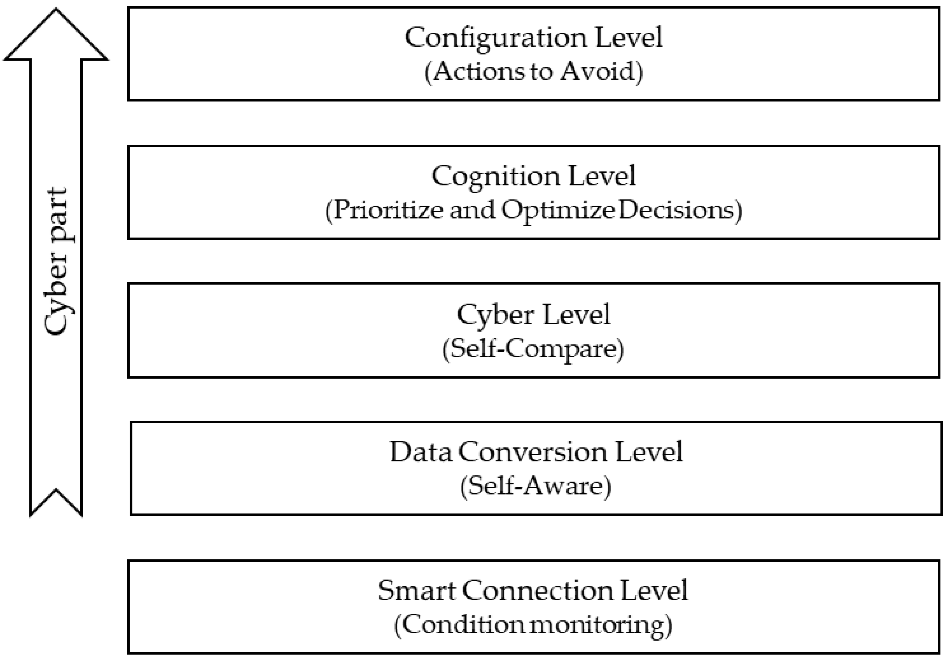
In the case of production systems, the increasingly wide range of products and the minimization of lead times have become even more crucial. These requirements lead to complex production systems operating in rapidly changing environments. The cyber-physical production system (CPPS), which uses data from production and logistics processes, can assist in planning, supervising, and managing production systems. Based on the availability of physical-manufacturing-process data and the flow of information, Lee et al. [10] proposed the 5C architecture (Figure 1) to provide a viable and practical guideline for implementing a CPS.
However, making decisions related to the design and management of the production system based on the information of the digital factory is a difficult task because there may be differences between the physical system and the digital twin (DT) that maps it. The differences primarily emerge because information about certain events that occur during a real process is not available or sufficiently accurate, or physics are not sufficiently considered during model creation. For example, consider a simple process in which a conveyor belt moves a workpiece between two machining positions. Based on the signals from the sensors placed in the dedicated positions, there is information about whether the piece is at the sensor and whether the belt is moving or stationary. Therefore, only in the digital twin monitoring the data of the PLC (programmable logic controller) deviations and blind spots can occur. These can be reduced by increasing the complexity of the model and/or by increasing the sensor level. However, all these solutions significantly increase costs, so the main goal is to find a solution that, in addition to existing sensorization and modeling simplifications, can reduce the differences between real and simulated processes in the digital-production system [1,2].
This paper presents an IIoT solution that serves as a complement to the digital twin and can be optionally deployed without disturbing the production system monitored. It is a crucial part of DTs, since it allows users to visualize the state of real-world systems more clearly without being physically present. One of the purposes of DTs is to provide an accurate visual representation of a system’s state. One feature of this kind of DT in a large production setting would be the quick diagnosis of a fault site. It is simple for maintenance teams to proactively identify the physical location of a problem, such as a workpiece becoming stuck or a sensor error. With the support of DT technologies, this specific technology is quickly advancing toward application in maintenance systems for augmented reality.
2. Literature Review
The authors prepared a brief international literature review on digital twins based on influential publications. Naturally, this summary could not cover the literature in detail. However, the key findings in the literature are summarized in the following paragraphs.
A literature review on DES and DT integration identified trends and challenges in this area, focusing on logistics processes [11]. Simulation environments capable of receiving and processing data from IoT devices in real time can form the basis of CPSs. In the near future, if ‘sensing shop-floor data’ become available, these real-time connected simulations could greatly increase the efficiency of manufacturing and logistics systems [11].
In their literature review, Lu et al. [7] envision the transformation of the manufacturing landscape as a potential effect of digital-twin-driven smart solutions. They found about 500 articles written between 2016 and 2020, based on which they identified a clear trend in the adoption of digital twins adoption. According to Lu et al., the necessary conditions to create a proper digital twin are a standardized information model, high-performance data processing, and a combination of industrial communication technologies [7].
Because the factory’s virtual replica (simulation) is actively linked to the factory floor this kind of DT is effective for factories. Moreover, the DT can monitor the factory, identify issues or less-than-ideal behavior, re-optimize the factory virtually (in the simulation), and then, after receiving approval, implement these changes back into the actual factory via connected control systems. All of this can be performed in decision-critical times [12,13].
Common industrial architectures have been extended in which the digital twin can be used to create a supervisory digital twin using real-time information from the physical system [14,15]. The addition proposed in the DES environment provides valuable information from the supervisory digital twin through a feedback loop, thus realizing the digital-twin process.
Sakr et al. [16] discuss digital equivalence as the primary goal of creating a digital twin, and simulations are an integral part of this process. However, DTs offer applications far beyond those of traditional simulations with the help of IIoT technologies, implementing various real-time synchronization solutions. A building aspect and an integrated use of digital twins in a DES environment is presented. The developed method is demonstrated through a semiconductor-production process. The proposed solution extends the use of DES-based digital twins in the CPPS environment [16].
Cai et al. [17] created a DT by implementing a sensor-data-integration and information-fusion approach to simulate machine tools in a safe, cost-effective, and efficient approach. They set the goal of achieving as accurate a representation of the physical-tool-wear process as possible. Their proposed technique, which can be used as a building block for a cyber-physical manufacturing system, was demonstrated on a three-axis milling machine. With the addition of a sensor, the specific characteristics of the machine were extracted. The data collected will significantly facilitate the monitoring of equipment and the prediction of possible faults [17].
Digital twins are becoming increasingly popular, even in application areas such as fault diagnosis, supervision, and optimization [18,19]. Another central element, as this article suggests, is the existence of online simulations and the improvement of their synchronization, which is also one of the critical challenges, as simulations themselves may not be entirely accurate due to their inherent simplifications and the age and wear of the systems represented. A state-synchronization methodology based on dynamic optimization is presented. It demonstrates and confirms the real-time applicability of the methodology in several scenarios [18].
In previous studies, digital twins and cyber-physical systems were described as crucial for managing manufacturing companies [20,21]. A digital model can improve performance and make manufacturing more efficient if it can correctly represent its physical counterparts at any time. These articles focus on the automatic generation of models in DES environments, which can significantly shorten the development phase and allow even short-term decision support in manufacturing. The authors of these articles created a laboratory-scale model with six different stations, on which they tested their proposed methodology [20,21].
A proof-of-concept for the use of the main components of I4.0 (DT and CPS) for process optimization and production-data analysis was presented [12]. Integrating a commercially available camera (Intel RealSense), which is very popular in research, into an automation system creates a connected system that updates the simulation in real time during execution, creating a DT. The implemented system provides a low-cost, scalable method for identifying and tracking the progress of products through the production line [12].
Digital twins for an experimental assembly process were created by Zidek et al. [22]. This involved the assembly of a 3D-printer extruder, which consists of several different components. During the implementation, accurate positioning was achieved using ultra-high frequency (UHF) tags and IoT tools. The process was created entirely in 3D, and the DTs’ simulation environment was Plant Simulation [22].
3. Test Environment
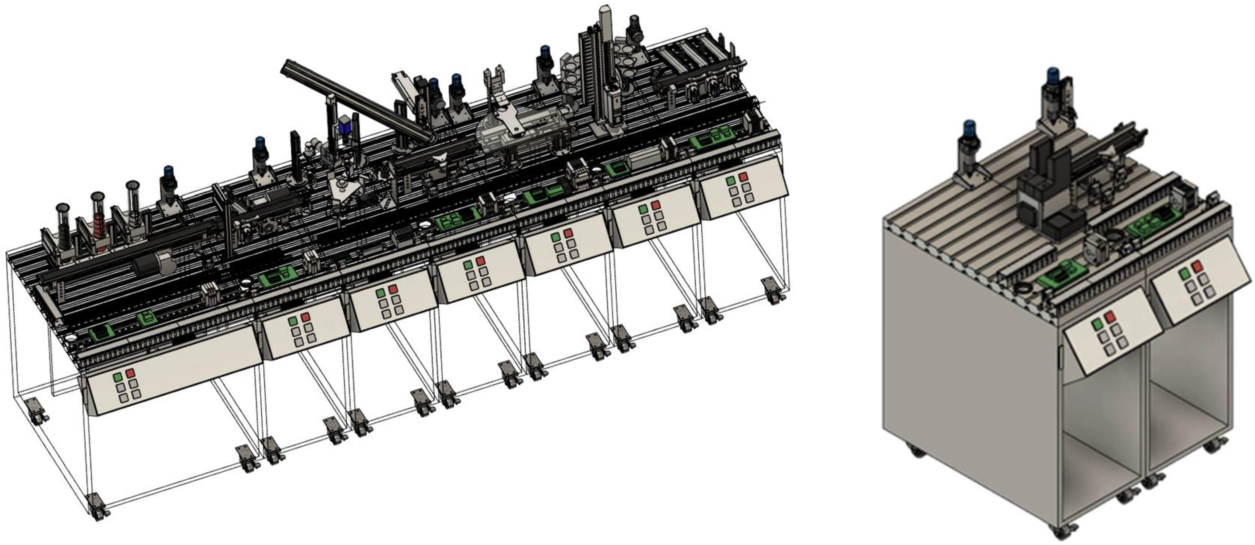
The test environment is based on the FESTO Didactic production line at the Industry 4.0 research laboratory of Széchenyi István University. The production line consists of several linked stations, built in a modular way, realizing a linear material flow. Each modular cell is equipped with its own PLC (S7-300 PLC), so it can operate independently. The production line covers the main workflows found in the industry: feeding, transfer, sorting, rotary table, assembly, storage, and robotic palletizing (see Figure 2). Regarding sensors, the focus is also on solutions used in industry, with inductive, capacitive, and color sensors on the production line. This sample system is not part of the manufacturer (FESTO)’s Cyber-Physical Factory product group, but has undergone specific developments over the years, to the point where it can now meet the main requirements [23,24,25,26] of I4.0 from both a sensing and a communication point of view. Therefore, this transformation process from a legacy system to an I4.0-capable system is not part of this article.
The production line was not entirely applicable for developing and testing the new DES (discrete-event simulation)-based DT framework. The line is designed for a small cylindrical workpieces, but a new workpiece was needed for the experiments; this workpiece was the authors’ smart IIoT (Industrial Internet of Things) device. Therefore, taking advantage of the line’s modularity, a station was selected that could be adapted to the required enclosure size, on which the desired experiments could be carried out in a reproducible way.
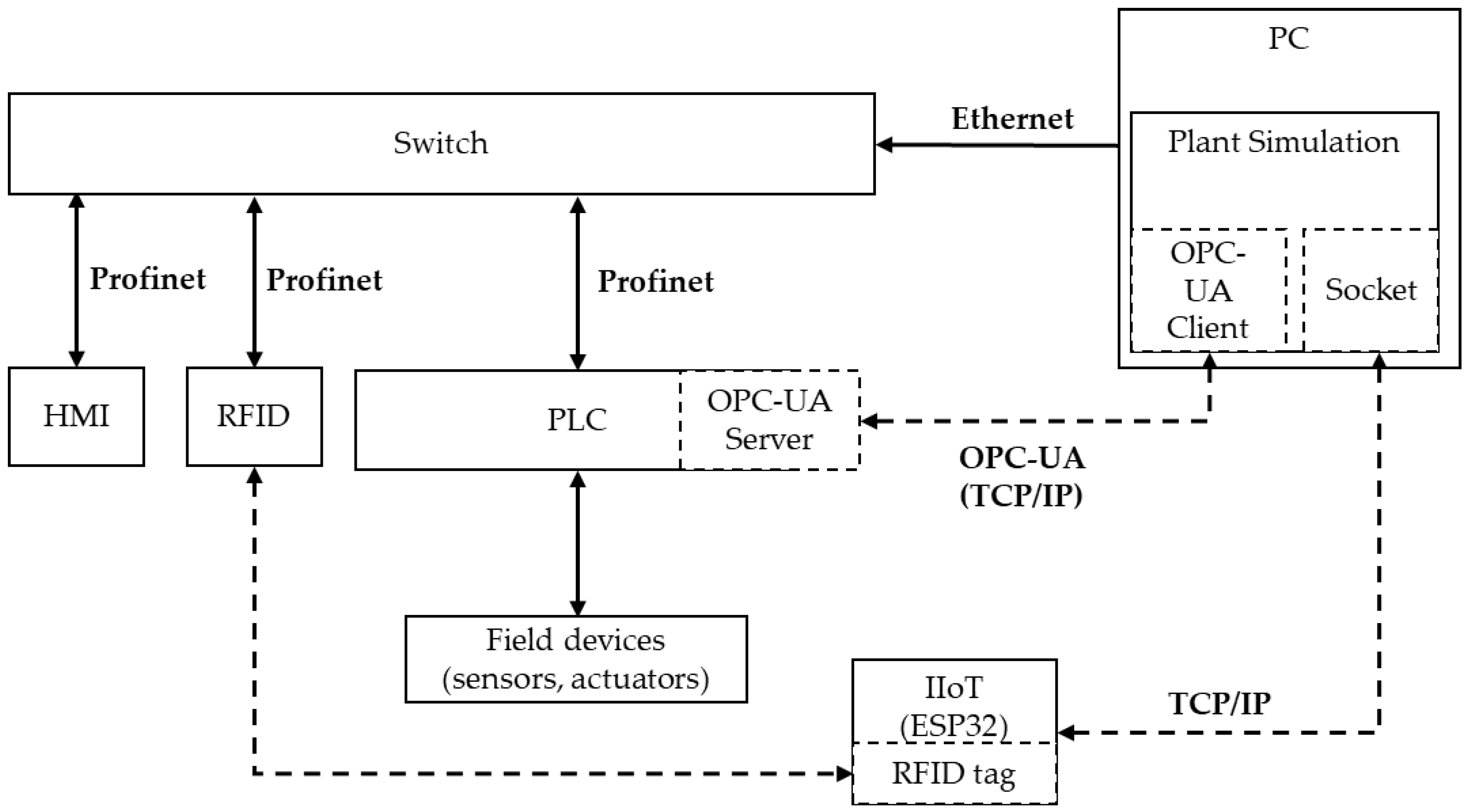
During the development of the test environment, the authors aimed to make it as close to a real industrial environment as possible, so modern and widely used industrial tools were applied for the PLC implementing the control and for the actuators and sensors. The created testbed (Figure 2) is an automatic feeding and a material-flow-transfer process. It contains a conveyor belt, three optical sensors (FESTO SOEG-L-Q30-PAS-2L Fiberoptic), and an actuator (stopper). The cell is controlled by an industrial PLC (Siemens S7-1200), to which a Rievtech HMI (human-machine interface) (RTS7070WE) and a Siemens SIMATIC RF180C RFID (radio-frequency identification) reader/writer integrated into the feeder are connected via PROFINET (process field network).
The physical system is connected to a Lenovo L580 (i5-8350U, 8GB DDR4-2400) laptop via Ethernet. The digital layer of the CPPS was created in the Siemens Tecnomatix Plant Simulation (v2101) software environment. The system architecture of the test environment is illustrated in Figure 3. The applied DES environment allows a high modeling level. In this type of modeling of manufacturing processes, the material flow and the movements induced by each discrete event are the relevant factors. The software includes the necessary interface (OPC-UA) to establish modern real-time/near-real-time network connectivity [27]. The OPC-UA and MQTT are the most widely used communication protocols in industrial automation and IoT, according to Profanter et al., who regularly use them in their studies on Industry 4.0 [28,29]. The Open Platform Communications Unified Architecture (OPC UA), a service-oriented machine-to-machine communication protocol mainly utilized in industrial automation, is described in the IEC 62541 standard. The scenario, including monitoring and control, is the most likely OPC UA application scenario. The OPC-UA is used to establish connections between a production process and a visualization system to monitor the state of the production process and other relevant information. Its other primary role is to provide a cross-platform communication protocol and an information model to describe transferred data [28,30]. The digital twin can communicate bi-directionally with the PLC via the OPC-UA information-modeling environment. The information model was created and configured using the Siemens OPC UA Modeling Editor (SiOME) software and contains the input and output parameters describing the physical system’s processes. The list of specific parameters is shown in Table 1. The OPC-UA server runs on the PLC (in-built), and the client runs in the Plant Simulation environment. Changes in the values of the monitored signals act as triggers in the simulation environment: as soon as the PLC publishes a signal change, it triggers a reaction in the digital model. The coordinated operation’s first step is to establish and maintain the connection. A 10-Hz PLC serves as the maintenance clocked variable; this is necessary because in longer time intervals without signal changes, e.g., in standby mode, the connection would otherwise be lost, and the data exchange between the two layers would stop. Due to its event-driven characteristic, the system is susceptible to signal failures, so if communication is interrupted or a signal is dropped, an immediate loss of synchronization occurs, and the digital model is likely to be incorrect. The failure of the digital twin does not affect the operation of the real system; rather, it only acts as a supplement, so potential communication failures do not cause downtime.
In the simulation software, the triggers for each event were connected after creating an ‘as-is’ model of the physical system, thus establishing the connection between the physical and digital layers. Plant Simulation continuously reads data in real time from the PLC via the OPC-UA. The DES model can display RFID information (Product ID), the number and position of products currently in the order system at a given time based on the presence sensor and RFID sensor signals, when a product is in these discrete positions, and the lead time from the production process to the test station.
During the testing process, the workpieces were identified before they were placed on the belt based on the information stored on the RFID tags. Once the reading was complete, the dispenser pushed the piece onto the belt, and the motor that drove the belt was started simultaneously. The workpiece on the belt stopped at the first detection point, and after a short waiting time, it started again. The process ended when the last detection point on the belt was reached. An actuator in the middle of the belt allowed the workpiece to be stopped so that the belt itself could remain in motion, but the piece being carried could not. This feature was necessary to provide a controlled, reproducible, and verifiable solution to improve the digital-twin synchronization and the tracking of the material flow.
An M5Stack Core2 microcontroller provided the additional inputs required for the part tracking via a software socket to Plant Simulation. The M5Stack Core 2 is an ESP32-based microcontroller with a built-in six-axis IMU (three acc.s and three gyros) (MPU6886), Bluetooth, Wi-Fi, capacitive touch screen, and built-in lithium battery (500 mA). The Core2 module is programmed in the ArduinoIDE programming environment, and it sends acceleration and gyroscopic data measured on X, Y, and Z axes to Plant Simulation via Socket object. Sockets also have a TCP/IP-based point-to-point connection, allowing online data exchange. The gyroscope and accelerometer were measured and set to the most sensitive mode, ±250 dps (degree per sec) for the gyroscope and ±2× g (where g is the gravitational acceleration, i.e., approx. 9.81 m/s2) for the accelerometer. Due to the sensitivity, the sampling was very dense, which caused difficulties in sending data to the PC, as the communication latency was excessively high to obtain valuable measurement points from the test. Therefore, the microcontroller was utilized to perform the calculations, in which the time factor is crucial. One of these events was the start of a workpiece on a tape, in which the acceleration was so fast that the communication delay would have made it undetectable if it had been processed on the PC afterward. Therefore, the device was used to map the workpiece motion between the sensing points in the DT as accurately as possible.
In a digital-twin environment, it is easier to implement various external data-collection devices and process the data. At the same time, the system that controls the production system can run without causing any disruption during development.
Thus, this method also ensures that the two systems are not necessarily dependent on each other, so it is possible to operate the production process without the digital twin and the feedback and intervention systems based on extended comprehensive data collection. The developed IIoT device sends a stream of data describing the movement of the workpiece at regular intervals. The dataset includes acceleration and angular-displacement data in the X, Y, and Z directions, the pitch and roll angles, and the sensor’s temperature.
4. Results and Discussion
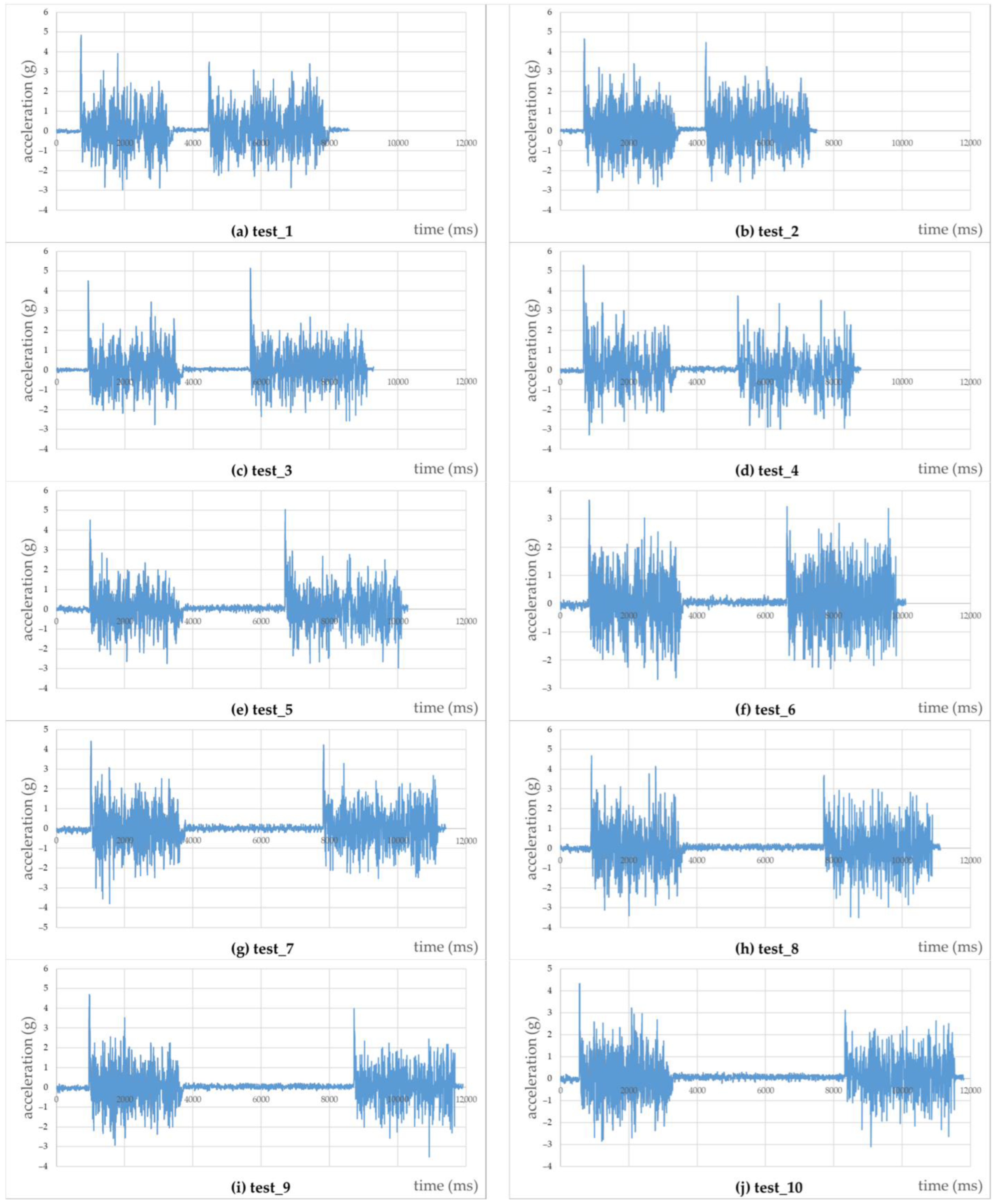
During the system’s operation, the DES is in online communication with the PLC managing the physical system and is continuously informed of the events detected and controlled by the PLC through the OPC-UA information model. Through the data exchange implemented, the simulation model can represent the processes of the physical system as a kind of digital shadow. However, even in the case of a simple material-flow process, discrepancies can easily arise, and the physical and digital layers are never the same, as different simplifications are needed in the model-building process. In addition to simplifications, another critical event that can interrupt the synchronicity between the two layers, even significant mismatches, is the occurrence of a faulty, unexpected state in the physical system. In the testbed system reported in this study, the authors induced an unexpected event utilizing an actuator that interrupted the continuity of the process. The PLC controlled the stopper, and the value of the corresponding output was also available in the simulation, but it was used only to check and validate the effectiveness of the authors’ method. Using the random generator of Plant Simulation, a stop signal was sent from the digital layer to the physical layer at intervals of 1–5 s (Figure 4, from (a) to (j); each pair, e.g., (a) and (b) means different tests, but under the same circumstances).
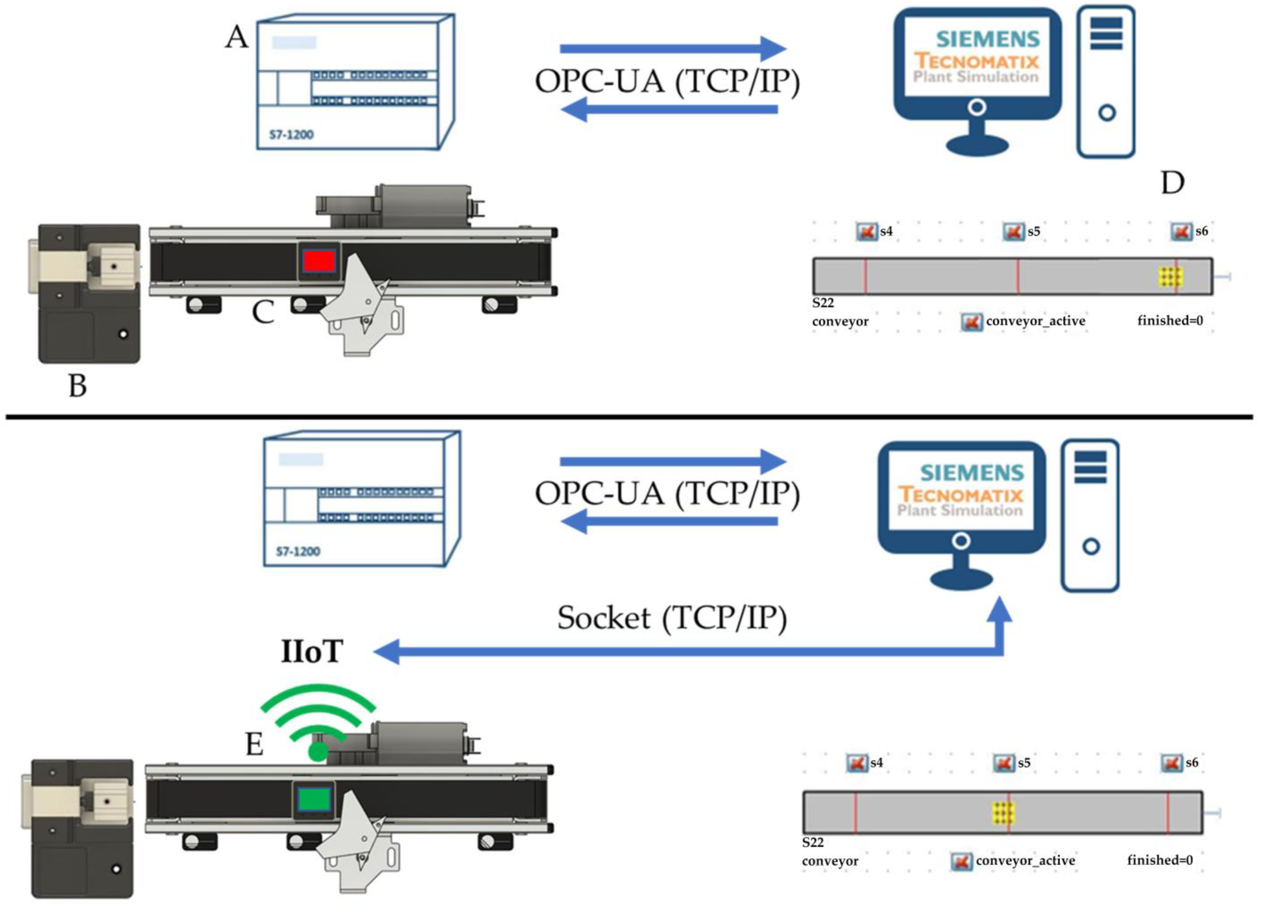
In response to a physical obstacle, the workpiece was stuck in the middle of the belt, while in the simulation model, the workpiece remained in motion without disturbance, as the model controller had no information about this. Figure 5 shows how the real and digital processes lost synchrony, impairing the visualization, which can be an essential consideration if it is necessary to monitor the real system remotely. The authors attempted to solve this problem by integrating a smart device into the system, which was also connected online to the simulation.
Through the communication links established, the DT created in the DES environment can pinpoint the position of the workpiece by monitoring the following relationships. The raw data from the IMU sensor is illustrated in the upper diagram in Figure 6, which clearly shows two distinct acceleration features for different states, with the lower amplitude sections representing the stationary position. In contrast, the sections with acceleration values that are orders of magnitude higher represent the movement of the workpiece on the conveyor. The incoming raw acceleration and gyroscope-angle data were processed in Plant Simulation. In the simulation environment, an algorithm was used to determine the scatter of the IIoT-tool acceleration data during an initialization phase before the start of the feeding process. The value is used as a reference value below. The results were increased by a safety factor (the standard deviation of the data during the initialization multiplied by 1.2) determined by experience. Finally, the calculated value was applied as a threshold for calculating the continuous moving standard deviation (in a window of ten measurements).
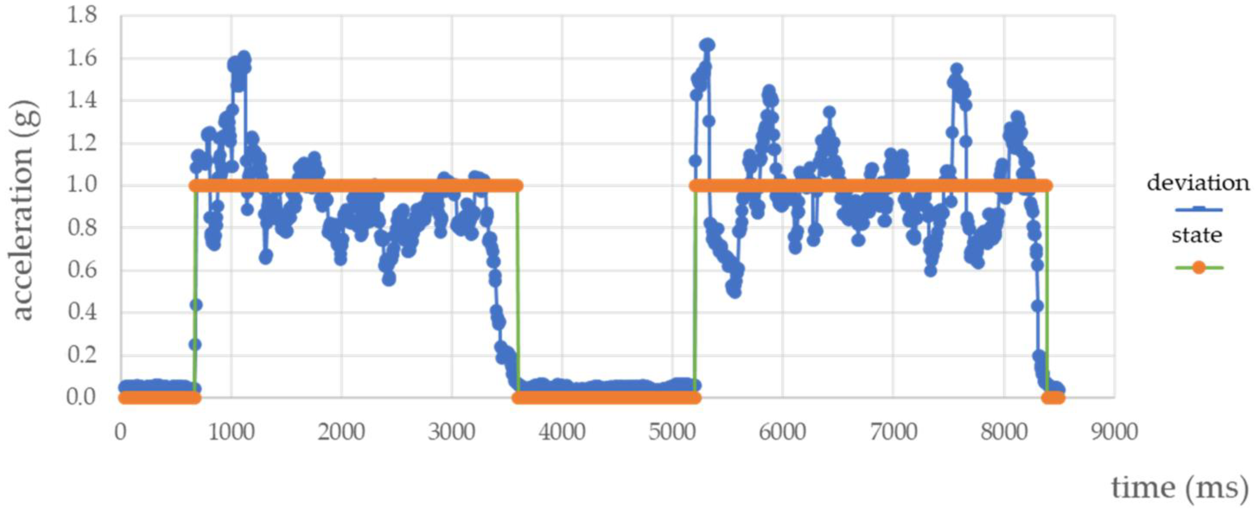
Figure 7 shows the state defined by the algorithm, with the state “0 “representing stationary and “1” representing moving. These state values were compared with the data describing the event from the PLC. If the line was in motion according to the PLC signals, the line was started in the digital space, but the IMU data were also retrieved in parallel. If the MEMS (microelectromechanical systems) sensor data also confirmed the f movement, the workpiece continued to move in the simulation; otherwise, the system generated an error message for the user at the HMI (human–machine interface) and in the simulation space as a pop-up message, and it stopped the operation of the conveyor with the PLC. In this way, errors are detected immediately, and unnecessary operations are avoided. Using this method in the simulation environment has the added benefit that the initial RFID piece identification in the digital space makes it possible to track which device each data string belongs to continuously, so users can always detect exactly which piece is stuck and where, and even which data string deviates from the usual, and by which device it is recorded. However, this pattern recognition is currently limited for comparing the time spent in each state.
Table 2 illustrates the accuracy of the developed method, which uses accelerometer data, to determine the time the workpiece spends in the stopped position. The elements of the table are as follows. The outage time (PLC) refers to the reference time (the current value of the variable parameter set in the PLC code) during which the actuator forms a barrier in front of the workpiece, preventing it from moving. In the experiments, this was the physical event about which the digital layer had no information, so a possible jam or anomaly was reconstructed. The outage time (digital twin) refers to the time of the anomaly detected in the Plant Simulation environment based on the IIoT-device data (Figure 7). The difference refers to the difference between the PLC (reference) and the calculated value. The accuracy refers to the percentage accuracy calculated from the difference. It shows how accurately the digital twin can represent an artificially created (controlled and verifiable) event in the physical system.
Based on the results obtained, it can be said that for the test environment created as the basis of the investigations, the proposed digital twin can better represent the material flow processes of the real system, as well as making it possible to fill the information gap, or ‘black box,’ between two discrete sensing points in the automation system under investigation. The magnitude of the outage time induced does not affect the detectability of the outage time by the proposed method. The accuracy of the method is most significantly affected by the noise of the low-cost IMU data used; hence, it can be observed in the data that not only a negative difference is possible, so even more than the jamming time of the physical product can be measured. The obtained accuracy proved to be sufficient in such a way that only a minimal difference between the digital twin and the physical system was observed in terms of the visualization of the material flow.
Comparing the results with a relevant paper, Ward et al. [12] used the OPC-UA to establish an information link between the digital twin (Plant Simulation) and the physical system (PLC), but used cameras to track the pallets and to provide a better visual representation. The images captured by the Intel RealSense cameras were processed using deep-neural-network techniques. As a result, Ward et al.’s proposed method is more accurate but more hardware- and computation-intensive. In addition, cameras are costlier than the IIoT device we propose. However, regarding scalability, it should also be mentioned that each pallet needs to have an IoT device attached to it in the proposed solution, so the number of pallets can reduce this advantage or even make it more expensive than a solution with cameras. Furthermore, if cameras are applied, their placement and the necessary illumination must be taken into consideration; depending on the environment, different blind spots and overlapping gaps can be created, making it difficult to detect the workpieces.
5. Conclusions
The sensing capabilities of the system under investigation greatly influence the DES-based digital twins’ robustness and accuracy. Under normal operating conditions, good results can be achieved without the detailed modeling of the physical processes, but disturbances caused by unexpected events are challenging to model. In the authors’ interactivity solution, the greater degree of freedom offered by the digital environment in terms of the connectivity that can be built was exploited, and it was possible to integrate additional devices into the system, which provided valuable information for a more accurate representation of real processes, thus supporting the visual overview and remote monitoring and decision making. In this paper, the authors presented an affordable IIoT-device-based sensor-data and -information fusion model to create a material-flow-synchronized DT solution. The tracking device used was an ESP32-based microcontroller with a built-in IMU; the sensor-based acceleration data were tested in combination with the existing model. In addition, the vibration data of the moving workpiece were collected and measured to generate a state-identification method. By applying this method, the synchronization of the physical system and the DT created in an online discrete-event-driven environment can be improved. Furthermore, the benefits of the proposed architecture do not interfere with the material-flow-control process, but only support it with additional information. Hence, the architecture increases the accuracy and visual representation of DTs, and it expands the usability of current DES for DTs within cyber-physical production systems.
Author Contributions
Conceptualization, G.D.M. and S.F.; methodology, G.D.M. and S.F.; software, G.D.M.; validation, G.D.M.; formal analysis, G.D.M. and S.F.; investigation, G.D.M. and S.F.; resources, G.D.M. and S.F.; data curation, G.D.M.; writing—original draft preparation, G.D.M. and S.F.; writing—review and editing, G.D.M. and S.F.; visualization, G.D.M.; supervision, S.F.; project administration, G.D.M. and S.F.; funding acquisition, G.D.M. and S.F. All authors have read and agreed to the published version of the manuscript.
Funding
This research received no external funding.
Acknowledgments
This paper was prepared by the research team, SZE-RAIL.
Conflicts of Interest
The authors declare no conflict of interest.
Abbreviations
| CPPS | Cyber-Physical Production System |
| CPS | Cyber-Physical System |
| DES | Discrete-Event Simulation |
| DT | Digital Twin |
| HMI | Human–Machine Interface |
| I4.0 | Industry 4.0 |
| ID | Identification |
| IIoT | Industrial Internet of Things |
| IMU | Inertial Measurement Unit |
| IoT | Internet of Things |
| LED | Light-Emitting Diode |
| MEMS | Micro-Electro-Mechanical Systems |
| MQTT | MQ Telemetry Transport |
| OPC-UA | OPC Unified Architecture |
| PLC | Programmable logic Controller |
| Profinet | Process Field Network |
| PS | Tecnomatix Plant Simulation |
| RFID | Radio Frequency Identification |
| SiOME | Siemens OPC UA Modeling Editor |
| UHF | Ultra-High Frequency |
| Wi-Fi | Wireless Fidelity |
References
- Monostori, L. Cyber-Physical Production Systems: Roots, Expectations and R&D Challenges. Procedia CIRP 2014, 17, 9–13. [Google Scholar] [CrossRef]
- Monostori, L.; Kádár, B.; Bauernhansl, T.; Kondoh, S.; Kumara, S.; Reinhart, G.; Sauer, O.; Schuh, G.; Sihn, W.; Ueda, K. Cyber-Physical Systems in Manufacturing. CIRP Ann. 2016, 65, 621–641. [Google Scholar] [CrossRef]
- Monostori, L.; Erdős, G.; Kádár, B.; Kis, T.; Kovács, A.; Pfeiffer, A.; Váncza, J. Digital Enterprise Solution for Integrated Production Planning and Control. Comput. Ind. 2010, 61, 112–126. [Google Scholar] [CrossRef] [Green Version]
- Tao, F.; Zhang, M. Digital Twin Shop-Floor: A New Shop-Floor Paradigm Towards Smart Manufacturing. IEEE Access 2017, 5, 20418–20427. [Google Scholar] [CrossRef]
- Ladj, A.; Wang, Z.; Meski, O.; Belkadi, F.; Ritou, M.; Da Cunha, C. A Knowledge-Based Digital Shadow for Machining Industry in a Digital Twin Perspective. J. Manuf. Syst. 2021, 58, 168–179. [Google Scholar] [CrossRef]
- Lu, Y.; Ju, F. Smart Manufacturing Systems Based on Cyber-Physical Manufacturing Services (CPMS). IFAC-PapersOnLine 2017, 50, 15883–15889. [Google Scholar] [CrossRef]
- Lu, Y.; Liu, C.; Wang, K.I.-K.; Huang, H.; Xu, X. Digital Twin-Driven Smart Manufacturing: Connotation, Reference Model, Applications and Research Issues. Robot. Comput.-Integr. Manuf. 2020, 61, 101837. [Google Scholar] [CrossRef]
- Tipary, B.; Erdős, G. Generic Development Methodology for Flexible Robotic Pick-and-Place Workcells Based on Digital Twin. Robot. Comput.-Integr. Manuf. 2021, 71, 102140. [Google Scholar] [CrossRef]
- Vieira, A.A.C.; Dias, L.M.S.; Santos, M.Y.; Pereira, G.A.B.; Oliveira, J.A. Setting an Industry 4.0 Research and Development Agenda for Simulation—A Literature Review. Int. J. Simul. Model. 2018, 17, 377–390. [Google Scholar] [CrossRef]
- Lee, J.; Bagheri, B.; Kao, H.-A. A Cyber-Physical Systems Architecture for Industry 4.0-Based Manufacturing Systems. Manuf. Lett. 2015, 3, 18–23. [Google Scholar] [CrossRef]
- Agalianos, K.; Ponis, S.T.; Aretoulaki, E.; Plakas, G.; Efthymiou, O. Discrete Event Simulation and Digital Twins: Review and Challenges for Logistics. Procedia Manuf. 2020, 51, 1636–1641. [Google Scholar] [CrossRef]
- Ward, R.; Soulatiantork, P.; Finneran, S.; Hughes, R.; Tiwari, A. Real-Time Vision-Based Multiple Object Tracking of a Production Process: Industrial Digital Twin Case Study. Proc. Inst. Mech. Eng. Part B J. Eng. Manuf. 2021, 235, 1861–1872. [Google Scholar] [CrossRef]
- Kritzinger, W.; Karner, M.; Traar, G.; Henjes, J.; Sihn, W. Digital Twin in Manufacturing: A Categorical Literature Review and Classification. IFAC-PapersOnLine 2018, 51, 1016–1022. [Google Scholar] [CrossRef]
- Eyre, J.M.; Dodd, T.J.; Freeman, C.; Lanyon-Hogg, R.; Lockwood, A.J.; Scott, R.W. Demonstration of an Industrial Framework for an Implementation of a Process Digital Twin. In Proceedings of the ASME 2018 International Mechanical Engineering Congress and Exposition, Pittsburgh, PA, USA, 9–15 November 2018; Volume 2: Advanced Manufacturing. American Society of Mechanical Engineers: Pittsburgh, PA, USA, 2018; p. V002T02A070. [Google Scholar]
- Alejandro Huerta-Torruco, V.; Hernández-Uribe, Ó.; Adriana Cárdenas-Robledo, L.; Amir Rodríguez-Olivares, N. Effectiveness of Virtual Reality in Discrete Event Simulation Models for Manufacturing Systems. Comput. Ind. Eng. 2022, 168, 108079. [Google Scholar] [CrossRef]
- Sakr, A.H.; Aboelhassan, A.; Yacout, S.; Bassetto, S. Building Discrete-Event Simulation for Digital Twin Applications in Production Systems. In Proceedings of the 2021 26th IEEE International Conference on Emerging Technologies and Factory Automation (ETFA), Vasteras, Sweden, 7–10 September 2021; IEEE: Piscataway, NJ, USA, 2021; pp. 01–08. [Google Scholar]
- Cai, Y.; Starly, B.; Cohen, P.; Lee, Y.-S. Sensor Data and Information Fusion to Construct Digital-Twins Virtual Machine Tools for Cyber-Physical Manufacturing. Procedia Manuf. 2017, 10, 1031–1042. [Google Scholar] [CrossRef]
- Zipper, H. Real-Time-Capable Synchronization of Digital Twins. IFAC-PapersOnLine 2021, 54, 147–152. [Google Scholar] [CrossRef]
- Rezig, S.; Ghorbel, C.; Achour, Z.; Rezg, N. PLC-Based Implementation of Supervisory Control for Flexible Manufacturing Systems Using Theory of Regions. IJAAC 2019, 13, 619. [Google Scholar] [CrossRef]
- Lugaresi, G.; Matta, A. Automated Manufacturing System Discovery and Digital Twin Generation. J. Manuf. Syst. 2021, 59, 51–66. [Google Scholar] [CrossRef]
- Lugaresi, G.; Matta, A. Automated Digital Twins Generation for Manufacturing Systems: A Case Study. IFAC-PapersOnLine 2021, 54, 749–754. [Google Scholar] [CrossRef]
- Židek, K.; Piteľ, J.; Adámek, M.; Lazorík, P.; Hošovský, A. Digital Twin of Experimental Smart Manufacturing Assembly System for Industry 4.0 Concept. Sustainability 2020, 12, 3658. [Google Scholar] [CrossRef]
- Lasi, H.; Fettke, P.; Kemper, H.-G.; Feld, T.; Hoffmann, M. Industry 4.0. Bus. Inf. Syst. Eng. 2014, 6, 239–242. [Google Scholar] [CrossRef]
- Hofmann, E.; Rüsch, M. Industry 4.0 and the Current Status as Well as Future Prospects on Logistics. Comput. Ind. 2017, 89, 23–34. [Google Scholar] [CrossRef]
- Oztemel, E.; Gursev, S. Literature Review of Industry 4.0 and Related Technologies. J. Intell. Manuf. 2020, 31, 127–182. [Google Scholar] [CrossRef]
- Dafflon, B.; Moalla, N.; Ouzrout, Y. The Challenges, Approaches, and Used Techniques of CPS for Manufacturing in Industry 4.0: A Literature Review. Int. J. Adv. Manuf. Technol. 2021, 113, 2395–2412. [Google Scholar] [CrossRef]
- Lelli, F.; Maron, G.; Orlando, S. Client Side Estimation of a Remote Service Execution. In Proceedings of the 2007 15th International Symposium on Modeling, Analysis, and Simulation of Computer and Telecommunication Systems, Istanbul, Turkey, 24–26 October 2007; IEEE: Piscataway, NJ, USA, 2007; pp. 295–302. [Google Scholar]
- Profanter, S.; Tekat, A.; Dorofeev, K.; Rickert, M.; Knoll, A. OPC UA versus ROS, DDS, and MQTT: Performance Evaluation of Industry 4.0 Protocols. In Proceedings of the 2019 IEEE International Conference on Industrial Technology (ICIT), Melbourne, Australia, 13–15 February 2019; IEEE: Piscataway, NJ, USA, 2019; pp. 955–962. [Google Scholar]
- Liu, C.; Vengayil, H.; Lu, Y.; Xu, X. A Cyber-Physical Machine Tools Platform Using OPC UA and MTConnect. J. Manuf. Syst. 2019, 51, 61–74. [Google Scholar] [CrossRef]
- Schleipen, M.; Gilani, S.-S.; Bischoff, T.; Pfrommer, J. OPC UA & Industrie 4.0-Enabling Technology with High Diversity and Variability. Procedia CIRP 2016, 57, 315–320. [Google Scholar] [CrossRef]
Figure 1.
CPPS 5C architecture, reformatted after [10].
Figure 1.
CPPS 5C architecture, reformatted after [10].

Figure 2.
FESTO Didactic line (left) and the created testbed (right).

Figure 3.
The architecture of the testbed.

Figure 4.
Raw acceleration data from the IIoT device. A stop signal was sent from the digital layer to the physical layer at intervals of 1000–5000 milliseconds (from (a–j); each pair, e.g., (a,b) means different tests but under the same circumstances, i.e., (a,b) 1000 ms, (c,d) 2000 ms, (e,f) 3000 ms, (g,h) 4000 ms, and (i,j) 5000 ms).

Figure 5.
System architecture (A—PLC, B—feeder, C—conveyor, D—digital twin, E—smart workpiece).

Figure 6.
Anomaly detection (raw acceleration data, event from IoT, event from PLC).

Figure 7.
State calculation from deviation data.


Table 1.
OPC-UA data table.
| Identifier | Data Type | Alias | Changed-Value Control | Availability |
|---|---|---|---|---|
| “10 Hz” | Boolean | 10 Hz | init | always |
| “PS_connected” | Boolean | PS_connected | init | always |
| “feeder_out” | Boolean | feeder_out | control | always |
| “feeder_in” | Boolean | feeder_in | control | always |
| “RFID_detect” | Boolean | RFID_detect | control | always |
| “RFID_read” | Integer | RFID_read | control | when detect |
| “feeder_drive” | Boolean | feeder_drive | control | always |
| “feeder_forward” | Boolean | feeder_forward | control | always |
| “feeder_backward” | Boolean | feeder_backward | control | always |
| “belt_SensorStartPos” | Boolean | belt_SensorStartPos | control | always |
| “belt_SensorStopPos” | Boolean | belt_SensorStopPos | measure | always |
| “belt_SensorEndPos” | Boolean | belt_SensorEndPos | control | always |
| “belt_Stopper” | Boolean | belt_Stopper | measure | always |
| “belt_drive” | Boolean | belt_drive | control | always |
Table 2.
Measurement data for determining the stoppage time of the workpiece.
| Test ID | Outage Time (PLC) (ms) | Outage Time (Digital Twin) (ms) | Difference (ms) | Accuracy (%) 1 |
|---|---|---|---|---|
| test_1 | 1000 | 1043 | 43 | 0.043 |
| test_2 | 1000 | 895 | 105 | 0.105 |
| test_3 | 2000 | 1963 | 37 | 0.019 |
| test_4 | 2000 | 1838 | 162 | 0.081 |
| test_5 | 3000 | 2999 | 1 | 0.000 |
| test_6 | 3000 | 3032 | 32 | 0.011 |
| test_7 | 4000 | 4028 | 28 | 0.007 |
| test_8 | 4000 | 4164 | 164 | 0.041 |
| test_9 | 5000 | 5037 | 37 | 0.007 |
| test_10 | 5000 | 5067 | 67 | 0.013 |
| Average | 67.6 | 0.033 |
1 The values were calculated as the ratio of difference to ‘Outage time (PLC)’.
Disclaimer/Publisher’s Note: The statements, opinions and data contained in all publications are solely those of the individual author(s) and contributor(s) and not of MDPI and/or the editor(s). MDPI and/or the editor(s) disclaim responsibility for any injury to people or property resulting from any ideas, methods, instructions or products referred to in the content. |
© 2023 by the authors. Licensee MDPI, Basel, Switzerland. This article is an open access article distributed under the terms and conditions of the Creative Commons Attribution (CC BY) license (https://creativecommons.org/licenses/by/4.0/).
Share and Cite
MDPI and ACS Style
Monek, G.D.; Fischer, S. IIoT-Supported Manufacturing-Material-Flow Tracking in a DES-Based Digital-Twin Environment. Infrastructures 2023, 8, 75. https://doi.org/10.3390/infrastructures8040075
AMA Style
Monek GD, Fischer S. IIoT-Supported Manufacturing-Material-Flow Tracking in a DES-Based Digital-Twin Environment. Infrastructures. 2023; 8(4):75. https://doi.org/10.3390/infrastructures8040075
Chicago/Turabian StyleMonek, Gergő Dávid, and Szabolcs Fischer. 2023. "IIoT-Supported Manufacturing-Material-Flow Tracking in a DES-Based Digital-Twin Environment" Infrastructures 8, no. 4: 75. https://doi.org/10.3390/infrastructures8040075