Article

Enhanced Road Safety with Photoluminescent Pedestrian Crossings in Urban Contexts

by
Tomás de J. Mateo Sanguino
*,
Manuel Joaquín Redondo González
,
Jose Miguel Davila Martin
and
José Manuel Lozano Domínguez
Escuela Técnica Superior de Ingeniería, Universidad de Huelva, Av. de las Artes, s/n, 21007 Huelva, Spain
*
Author to whom correspondence should be addressed.
Infrastructures 2024, 9(3), 60; https://doi.org/10.3390/infrastructures9030060
Submission received: 8 February 2024 / Revised: 7 March 2024 / Accepted: 12 March 2024 / Published: 15 March 2024
(This article belongs to the Special Issue Road Systems and Engineering)

Abstract

:
The safety of roads in urban areas is a major concern for governments, demanding innovative solutions to enhance pedestrian safety. This paper introduces a novel approach to crosswalks by integrating resin with photoluminescent additives, offering a significant boost to road safety. A thorough methodology was employed to assess its effectiveness, covering mechanical, lighting, and vibroacoustic aspects, alongside a photogrammetric analysis of real-world experiments. The material exhibited noteworthy mechanical properties, displaying consistent tensile strength, load capacity, and strain values with a remarkable Shore A hardness. After 20 min, luminance values peaked at 68 mcd/m2, surpassing standard vehicle headlights at 100 m. Additionally, vibroacoustic analysis highlighted a noticeable relationship between vehicle speed and sound bandwidth, indicating the system’s potential to alert pedestrians. Tests revealed that the proposed system significantly decreased the average vehicle speed by 36.96% compared to conventional crosswalks, with a 27.80% reduction when drivers yielded to pedestrians. Furthermore, a survey involving 35 participants, focusing on the knowledge of road safety regulations, behavior, signage, and visibility, found positive results regarding accident reduction. The estimations indicate potential decreases of 26.26% in injuries and 35.4% in fatalities due to improved road conditions, 26.58% in injuries and 53.16% in fatalities resulting from reduced average speeds, and 52.56% in injuries and 79.91% in fatalities through enhanced road education. This underscores the multifaceted impact of the system on urban road safety.

1. Introduction

Traffic accidents involving pedestrians are a significant road safety problem. According to authorities, there were 10,461 traffic accidents in Spain during 2021, the country where this work is focused [1]. Of the total, 20% resulted in deaths, 48% involved people aged 65 or older, 63% were male, 65% occurred due to vehicle collisions, and 43% happened at night without artificial lighting on the road. Among the most common causes are the errors and distractions of drivers (8.25%), the lack of civic education (7.87%), poor road conditions (6.80%), and traffic signaling (6.58%). The distance at which drivers start to brake is critical in the accident severity and its prevention. So, improving drivers’ perceptions of pedestrians is a key goal to decrease fatalities and injury severities [2].
State-of-the-art solutions aimed at reducing accidents can be classified into active systems in vehicles and roads, both with significantly different limitations. Within the first group, advanced driver-assistance systems (ADASs) based on cameras and sensors are being introduced by manufacturers in mid-range vehicles [3,4]. Nevertheless, the acquisition of ADASs is still limited due to their high cost and the fact that they do not reach all users. Although ADASs are being deployed in high-end or mid-end vehicles, they are not deployed in low-end vehicles. The latter are mostly utilized by commercial companies (e.g., delivery agencies, carpentry, service sector, etc.) and do not include motorcycles, buses, trucks, and emergency vehicles (e.g., ambulances). Yet, another limitation is that ADASs are semiautonomous and not infallible. They currently have a maximum vehicle autonomy level of 4 out of 5, resulting in several deaths and injuries throughout the world. Another limitation is the old average age of automobiles [5]. Unless ADASs are incorporated by their owners, old cars will never carry them. This is unfeasible due to the hardware and software requirements, typically requiring a front RADAR, eight video cameras, 12 ultrasound sensors, a navigation map, a motherboard, and WiFi/5G connection [6]. For all the above, these systems only belong to car owners and are not permanently available on public roads.
Regarding road systems, there are different concepts in terms of size, price, type of installation, and availability. The most important ones go from basic road markers with illuminated canopies positioned above crosswalks to speed bumpers equipped with passive lighting, traffic lights activated either manually or by sensors, active lighting tiles, crosswalks featuring lighting indications, speed limit detection, or an active sensor barrier. A further review on road systems is available in [7,8]. The drawbacks of road systems in the literature include the following:
-
The absence of an established correlation between the improvement of accident rates and the visibility of road markings. This deficiency in relational knowledge is attributed to a scarcity of studies, with the exception of those conducted by national authorities (e.g., the General Directorate of Traffic) or research projects such as COST 331, IMPROVER, and RAINVISION [9,10,11].
-
Most solutions consist of patents not yet commercially available.
-
The acquisition of infrastructures by administrations mainly based on economic criteria (i.e., not always the safest).
-
Existing solutions generally require power lines and civil works for their installation (i.e., they are dependent, vulnerable to surges and costly).
For these reasons, classic speed bumpers, elevated concrete crosswalks, and the signaling of pedestrian crossings with passive reflectors or luminous canopies are still the most widely used and seen solutions in cities today. A thorough review on these approaches can be found in [12].
This work focuses on a set of road systems with the aim of reducing pedestrian accidents with vehicles through the application of the photoluminescence phenomenon. While electroluminescence occurs because of an electric current passing through a material only when the source is active (i.e., it requires electricity), photoluminescence consists of a natural or artificial radiation that illuminates a substance that returns its own light beyond the activation time of the source [13]. It has recently started to be used as an additive pigment combined with plastic, metallic, ceramic, or binder materials for the beautification of architectural elements in urban infrastructures [14]. For instance, Ambient Glow Technology (MN, Hamburg, New York, USA) registered the AGT™ Glow Stone brand for the decoration of concrete-based surfaces in toilets, gardens, and play areas.
Photoluminescence has been used for road marking to a lesser extent. The motivations to apply it have been the reduction in costs due to road lighting [15] and the integration of safer and more efficient urban services for certain groups of users (e.g., cyclists). For instance, the Texas Transportation Institute (TTI) and Texas University (Austin, TX, USA) successfully completed, in 2016, a demonstrative green bike lane with photoluminescent paint to increase mobility, security, and connectivity. Previously, the company Pro-Teq Surfacing (Cambridge, UK) developed a procedure based on three layers of polyurethane, photoluminescent spray coating, and polyaspartic sealing surfaces for asphalt, concrete, or wood applied on a 150 m2 pedestrian path called Starpath [16]. With a similar purpose, Studio Roosegaarde (Oss, The Netherlands) transformed a highway to delimit its continuous longitudinal marks with a mixture of photoluminescent powder and road paint [17]. Nonetheless, the utilization of photoluminescent substances in road signage has been underexplored [18]. As far as the authors know, there is no prior research in the current state of the art specifically applied to pedestrian crosswalks.
The solution proposed in this manuscript falls within the field of road safety in terms of transport, telecommunications, and other infrastructures, with inorganic chemistry being the essential technology that facilitates it. The classification according to the UNESCO nomenclature [19] includes codes 3327 (Transportation Systems Technology), 3329 (Urban Planning) and 3303 (Chemical Engineering and Technology). The goal of this research is to influence behavior of road users as a strategy to sustain the goal of ‘zero victims’ in line with the policy pursued by countries such as Sweden and Finland or the European Union itself [20]. This is also supported by the DGT— the Spanish acronym for the General Directorate of Traffic—through several initiatives that include the improvement of urban mobility, advanced technologies at the service of people, and smart and safe cities [21].
Studies have proven that more severe traffic calming measures provide greater speed reductions and therefore fewer accidents [22]. In correlation, the research hypothesis of this work is to demonstrate whether improving the perception of pedestrian crossings could help enhance driver behavior to reduce speed and consequently the rate of accidents (i.e., it is so important to see as to be seen). The current manuscript aims to advance beyond prior works [23], introducing a novel crosswalk approach based on innovative signaling. Accordingly, the contributions of this work are the following:
-
Use mixtures of resins and aggregates cold-injected on silicon molds to manufacture road tiles in a novel way not previously addressed in the state of the art;
-
Carry out a holistic experimentation to validate the mechanical, optical, and functional properties of the system;
-
Assess the feasibility of such a system to influence the attitude of users in a way that improves road safety for pedestrians.
To this end, this manuscript is structured as follows: Section 2 describes the proposed pedestrian crossing, along with the materials and methods used in the manufacture. Section 3 discusses the mechanical, optical, and functional properties of the system. Section 4 presents the experimentation carried out with the crosswalk. Section 5 provides a detailed discussion of the results. Finally, the manuscript presents the conclusions and future works.

2. System Description

This section is structured into several parts, starting with a general overview of the novel crosswalk. It delves into specific features like photoluminescence, reflectivity, durability, acoustic, anti-sliding, removability, and sustainability. Then, the manuscript provides detailed insights into the design, materials, and manufacturing processes, including the composition of the crosswalk parts, pigments, and coatings. The section also includes a description of the manufacturing method, with details of the surface treatment and the mechanical tests performed.

2.1. General Description

This paper introduces an innovative crosswalk design utilizing new materials and configurations to create road markings based on topology, length, and quantity (Figure 1). The tiles aim to replace traditional crosswalks with durable elements, utilizing photoluminescence for sustainable and safer illumination in low- or no-light conditions. Extensive studies, as detailed in [24], have demonstrated its benefits for road safety. The proposed solution extends its applicability to various horizontal signage types, including discontinuous transverse markings, arrows, inscriptions, curbs/islets marking, and other road markings. Compared to conventional methods involving acrylic paint, two-component paint, or cobblestone-based solutions, the proposed signage offers several technical advantages:
-
It reduces municipal maintenance costs by eliminating the need for periodic repainting.
-
Its installation requires only adherent fastening elements or mechanical anchoring, enabling its reuse without civil works.
-
It enhances visibility in low-light conditions, thereby improving perception.
-
It operates independently of electrical lighting sources, eliminating energy dependence which is common in active road marking systems.
The pedestrian crosswalk, defined by reversible tiles featuring two identical faces, maintains a maximum height of 15 mm across all points once integrated into the public thoroughfare. The variation in elevation between the various pieces within the crosswalk assembly complies with the restriction outlined in the regulation, ensuring that the leading edge does not exceed 5 mm under any circumstance [25]. The assembly comprises two types of pieces: square tiles measuring 500 × 500 mm and ramps measuring 500 × 250 mm. Both consist of male/female dovetail-type elements that protrude/enter, facilitating the cohesion of the diverse tiles and ramps constituting the ensemble. These elements include both the white and black colors demarcating the crosswalk. Figure 2 illustrates the design of the upper face of a tile, which mirrors the identical pattern on its lower face, as well as the design of the upper face of the ramp, featuring a flat lower surface.
Corrugated strips have been incorporated into the tile-type modules. These strips exhibit an amplitude of 15 mm and a ridge spacing of 100 mm. Each strip is 15 mm wide and stands 5 mm above the base on which it is positioned. Furthermore, both the tile-type and ramp-type modules feature a button-type texture, with a height of 1 mm and a diameter of 8 mm, spaced at a center-to-center distance of 15 mm.
The solution involves a photoluminescent substance with a whitish appearance in daylight, emitting passive light in partial or total darkness without requiring a power source. This ensures sustainability and energy independence compared to active road signage systems. The proposed photoluminescent blue color can be varied for different light effects (e.g., white, green, purple, or orange). The material is water-resistant, and light intensity can be adjusted within a 20–50% range of the base material. The illumination quality, rated on a scale of six values (A, B, C, D, E, S), corresponds to level 2 per DIN 67,510 specifications [26], indicating the easy recognition of photoluminescent signals in areas under constant light.
The proposed material incorporates glass microspheres to enhance the visibility of road markings at night by reflecting light from vehicle headlights [27]. This combination with the photoluminescent substrate amplifies reflective effects, particularly in low-contrast pavements or over longer distances, setting it apart from conventional solutions. The improvement is especially pronounced in wet conditions, where retroreflection typically decreases by 15–40% [28]. The glass microspheres used have specific characteristics, including a silicic sodium–calcium crystal composition, sphericity exceeding 70%, bulk density between 1.55 and 1.65, refractive index between 1.5 and 1.55, and a diameter range of 60–850 μm, applied at a rate of 500 g/m2.
The system’s body utilizes plastic materials combined with additives as a strategy to extend the system’s lifespan. This approach aims to gradually enhance the desired effects as the road system materials undergo wear. Specifically, polyol-isocyanate resins resistant to solar exposure and hot washing up to 100 °C are employed. The white components are colored with RAL 9016 (B-118 reference per UNE 48,103 standard), while RAL 9017 black pieces are positioned at ground level to facilitate pedestrian passage [29]. Both lower and upper sides share identical construction features, enabling the rotation of pieces in case of wear to effectively double their lifespan without requiring replacements.
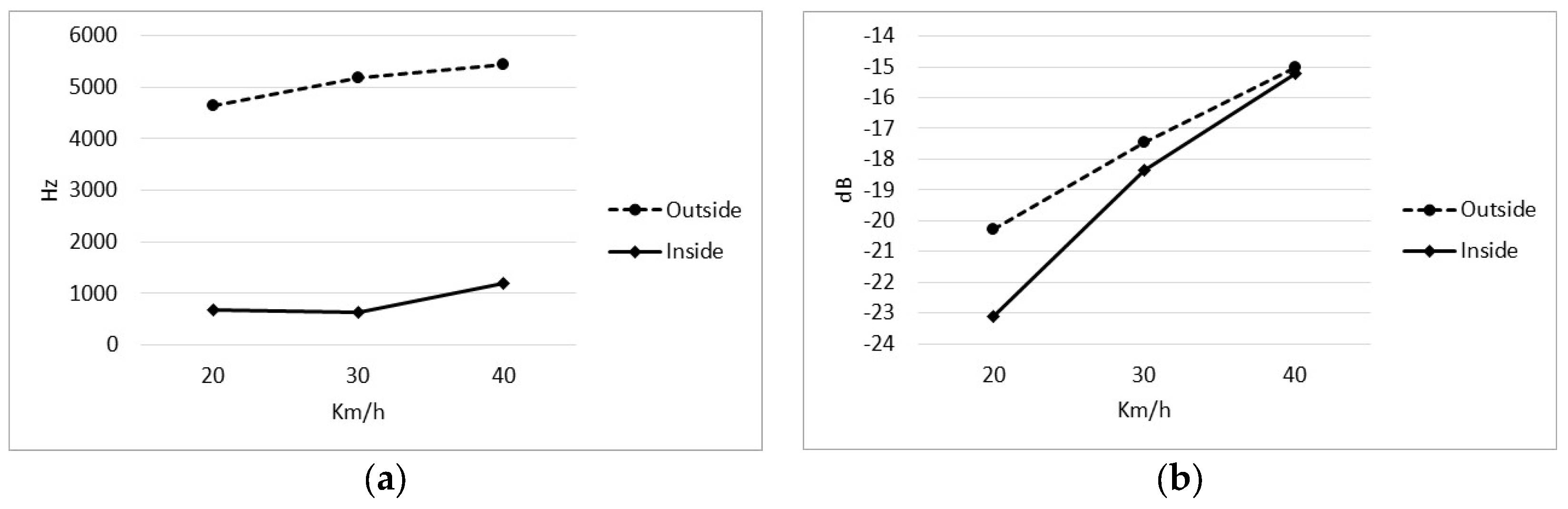
The system components feature a surface texture designed to generate mechanical and sound effects during vehicle operation. The primary goal is to alert drivers to adjust their speed according to road limits, supported by research indicating that sound and vibration impact can reduce accident occurrences [28]. This textured surface serves as a warning element for drivers, with specific dimensions and distances calibrated to activate when speeds surpass predefined thresholds based on the road type (e.g., 20 km/h, 30 km/h, or 50 km/h). The proposed button-type texture is intended to transmit vibrations through vehicle tires, increasing noise. This function is particularly beneficial for alerting pedestrians to the presence of electric vehicles and guiding visually impaired individuals. Notably, this approach surpasses other solutions, such as side markings on highways, which require refreshing the texture by adding new film thicknesses during road signage repainting.
This system has an anti-slip property which is achieved by combining two elements [30]. Firstly, the base material includes an anti-slip additive with angular corundum or Al2O3 particles (non-carcinogenic, non-toxic), sized between FEPA 20 and 36 (1190–425 μm). Secondly, the components are designed with a dual-effect anti-sliding texture. The macro texture consists of drainage channels for efficient water removal, improving the crosswalk’s performance in humid conditions. Additionally, the micro texture, with specific patterns, enhances responsiveness, preventing skidding for both pedestrians and vehicles (e.g., bicycles or scooters).
The pieces are affixed to the roadway using anchor bolts, with the option of considering chemical adherent fixing. Adherent elements may include temperature-hardening bituminous binders like bitumen, asphalt, or tar. However, for the case study, mechanical fixation is preferred, allowing easy removal and replacement by road workers without specific training, particularly useful during road resurfacing. Anti-vandalism fasteners with a steel bolt insertion are employed to prevent unauthorized removal or elevation due to long-term traffic vibrations. The height of the crosswalk parts adheres to current local traffic regulations to ensure vehicle integrity and occupant safety [25,28].
Traditional crosswalks, painted with white acrylic water-based paint, incur costs ranging from EUR 60 to 150 per crosswalk with 5–12 bands. The use of white polyurethane paint raises the cost to EUR 135–200, and employing granite pavers further increases it to EUR 950–2200. In contrast, the estimated cost of a photoluminescent crosswalk is about EUR 767–1841, presenting a middle-ground and financially viable solution. Moreover, conventional streetlamps, illuminating a crosswalk for 2 years, consume 2920 KWh of energy, resulting in a carbon footprint of 1080.40–405.14 Kg of CO2 emissions. Switching to LED lighting reduces the power consumption to 1094.96 KWh, leading to a monetary saving of EUR 6.29–16.77 based on the European Trading Scheme’s annual average price of CO2 emission rights [31]. This saving is attributed to the inherent self-illumination of the proposed photoluminescent crosswalk.

2.2. Materials and Methods

The tiles and ramps of the photoluminescent crosswalk are constructed using a thermosetting polyurethane resin polymer as the base material. The polyurethane resin is derived from two components: Polyol G0181RPC P-SL 120 000 and Isocyanate G0181RPC I-SL000 221. This transparent resin is specifically designed for vacuum casting, ensuring optimal performance. This product is mercury-free and meets the compliance standards set by European directives on the restriction of hazardous substances (RoHS), namely 2002/96/EC [32], 2000/53/EC [33], 2000/11/EC [34], 2011/65/EU [35], and 2017/2012/EU [36]. Additionally, the resin exhibits very high UV stability, and its composition allows for easy polishing and coloring. For instance, its transparency enables efficient blending with photoluminescent powder and pigments. Table 1 provides an overview of the physical properties of the components, including the color, aspect, viscosity, and density at 25 °C. Complementarily, Table 2 outlines the mechanical and thermal properties of the polymer, with the average values obtained through measurements on specimens subjected to post-curing conditions (2 h at 70 °C + 16 h at 100 °C + 24 h at room temperature) in accordance with the manufacturer’s specifications.
The white-colored tiles and ramps are integrated with photoluminescent powder, with the specific type utilized being MHB-5B, procured from Zhejiang Minhui L&T Co., Ltd (Jinhua, China). After exposure to sunlight for 10 to 30 min, this photoluminescent powder exhibits a residual glow that persists for more than 12 h. It is non-radioactive, non-toxic, highly weather-resistant, chemically stable, and boasts a shelf life of 15 years. The chemical composition of the photoluminescent powder is Sr4Al14O25: Eu+2, Dy+3, a rare earth-doped strontium aluminate. Its appearance is light white under daylight conditions and transitions to a bluish hue under low-light conditions. Table 3 details the characteristics and properties of the utilized photoluminescent powder. It not only conforms to the US standards specified in ASTM F963-16 (Consumer Safety Standard Specification for Toy Safety) [46] with respect to the total lead (test method CPSC-CH-E1003-09.1) [47] and soluble heavy metal (ASTM F963-16, Clause 8.3), but it is also registered in compliance with the EU REACH standard under REACH Regulation (EC) No 1907/2006 [48].
White tiles and ramps, incorporating white pigment 501 (WCP0501-0.1 by Castro Composites, Pontevedra, Spain), exhibit a medium viscosity paste color concentrate designed for the pigmentation of polyester or vinyl ester resins. This concentrate, with a viscosity, at 25 °C, of 12.5 dPa.s and an acid number of 25 mg KOH/g, is also suitable for gel coats and top coats with a similar composition. The produced white tiles and ramps, according to the RGB color model obtained with the GIMP application, exhibit values of 231, 235, and 238. This corresponds to RAL 9003 (as per https://hextoral.com/rgb-to-ral/, accessed on 13 March 2024). In this context, a difference of Δ = 4.5541 with RAL 9016 as required in traffic white colors was ascertained, signifying a 5.13% variance. Regarding the black-colored tiles and ramps, the coloration is accomplished using CASTRO Composite’s black pigment, specifically identified as DTH9002D-0.03. This concentrated dye, formulated for exterior applications and compatible with both solvent- and water-based products, has a density of 1.05 g/cm3 ± 0.001 and a non-volatile content of 30% ± 8%. Also, according to data from the GIMP application, the black tiles and ramps obtained RGB values of 38, 37, and 45, which corresponds to RAL 5008 (according to https://hextoral.com/rgb-to-ral/, accessed on 13 March 2024). It gives a difference of Δ = 6.8499 with RAL 9017 required in traffic black colors, assuming a 7.72% difference. To calculate the percentage difference between black and white colors compared to those used in traffic paint, it has been considered that the total difference between RAL 9016 and RAL 9017 is Δ = 88.7364.
As another component, a varnish from Montana Colors based on solvent-based thermoplastic acrylic resins was used, whose main characteristics are very fast drying, good hardening, excellent adhesion, high gloss, durability, easy application and repainting, good elasticity, outstanding water resistance, no yellowing and good UV performance (see Table 4). Finally, glass beads made of silica-sodium-calcareous glass were used as the reflective material (see Table 5).
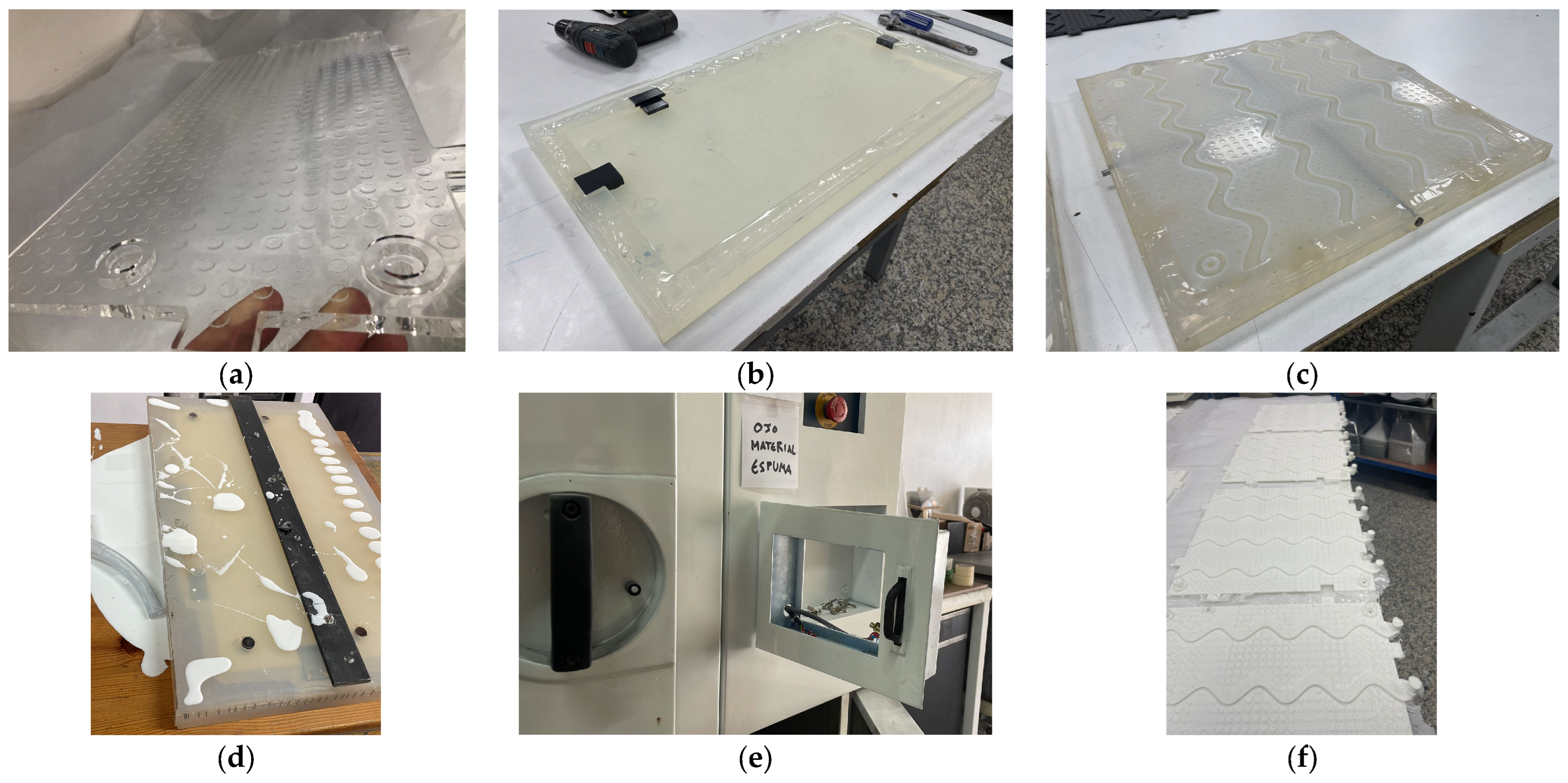
To mold the resin used, two methods can typically be used: (1) the vacuum casting machine process and (2) the hand casting process. In this instance, the selected procedure was the former, utilizing a vacuum casting machine. Prior to the resin casting, it was imperative to fabricate silicone molds from master molds to produce the two different parts (i.e., tiles and ramps). Once the silicone molds were prepared, the resin was cast following the manufacturer’s procedure, which entailed the following steps: (1) preheating the polyaddition molds to 70 °C, (2) weighing the isocyanate portion in the upper glass, ensuring the inclusion of the residual product, (3) weighing the polyol portion into the mixing vessel, (4) subjecting the mixture to a 10 min vacuum, (5) pouring the isocyanate portion into the mixing vessel, (6) stirring until the mixture achieved complete clarity for at least 2 min at 25 °C, (7) pouring the mixture into the silicone mold, (8) placing the mold in an oven at 70 °C for approximately 120 min, contingent upon the thickness of the piece, and (9) cooling the mold with compressed air before demolding the parts. Finally, the pieces were extracted from the mold, and the burrs resulting from excess resin that accumulated in the joint areas between the mold and the part during the injection process were eliminated to obtain a clean and imperfection-free piece through cutting, sanding, and polishing techniques. Figure 3 illustrates the complete manufacturing process of tiles and ramps, where the same silicone mold was used to produce different tongue-and-groove joints using incoming and outgoing inserts. Further specifics, including the mixture proportion by weight and the mixing and demolding times, are provided in Table 6.
All black and white tiles and ramps were subjected to a four-layer surface treatment. Three coats of varnish and a coat of glass beads were applied. Initially, a coat of varnish (i.e., layer 1) was administered to the surfaces. Subsequently, and while still in a wet state, glass beads (i.e., layer 2) were evenly distributed at an approximate rate of 500 g/m2. Following the complete drying and fixation of the glass beads from the first varnish layer, two additional varnish coats were sequentially applied (i.e., layer 3 and layer 4), adhering to the manufacturer’s prescribed repainting intervals between each application.
Due to the lack of knowledge about applications in this field similar to the proposal, it became imperative to manufacture a series of samples encompassing varying material percentages (i.e., photoluminescent powder, glass beads, and different pigments). The objective was to achieve an equilibrium between durability and the desired photoluminescent properties. Initially, it became apparent that polyurethane-based mixtures did not meet the requisite criteria, ultimately leading to the utilization of a polyol-isocyanate mixture. Specifically, the polyurethane resins PU212 and PU28LE from the manufacturer Axson were the materials mainly considered. PU212, boasting a density of 1.14 g/cm3, showcased commendable hardness, flexural modulus, and strength, albeit with a slightly inferior tensile strength compared to polyol-isocyanate’s 65 MPa. PU212 was also noted for its translucency, which adds to its aesthetic appeal in certain applications where mixing with other color pigments is required. However, PU212 exhibited a Shore D hardness of 80, while polyol-isocyanate and PU28LE both had a Shore D hardness of 85. Conversely, PU28LE demonstrated a higher tensile strength of 75 MPa and an impressive flexural modulus of 2800 MPa, surpassing PU212 in these aspects. However, both PU212 and PU28LE exhibited lower mechanical strength and impact resistance in comparison to polyol-isocyanate. Despite this drawback, PU28LE stood out with its excellent thermal resistance and compliance with regulatory standards. However, PU28LE’s more whitish appearance made it more challenging to blend with other color pigments compared to polyol-isocyanate, which integrated better with various pigments. According to the tests, the final white modules consisted of a composition comprising 87.48% polyol-isocyanate resin, 9.84% photoluminescent powder, and 2.68% white pigment. In contrast, the black modules were formulated with 97.03% polyol-isocyanate resin and 2.97% black pigment. For reference, Figure 4 shows an example of different samples made with various mixtures of the materials tested.

3. Mechanical Analysis

The experimental procedures conducted in this study involved three distinct mechanical tests. Firstly, stain resistance was evaluated according to the IT-LB-0038 standard [57] from Labiker, encompassing both traces and films, with one and four trials, respectively. Secondly, tensile properties were analyzed following the IT-LB-0041 standard [57], utilizing a CODEIN 20 kN multi-test machine with precision exceeding 1.00%. Samples, prepared by carving, underwent testing at 20 °C and 50% humidity, with a test speed of 10 mm/min. Five specimens of specific dimensions (width 10.0 mm, thickness ranging from 5.5 to 5.7 mm, cross-sectional area ranging from 55.0 to 57.0 mm2, reference length L0 96 mm) were employed. Lastly, Shore A hardness was determined using a durometer, following the IT-LB-0041 standard, with four measurements conducted. The meticulous adherence to standard protocols, coupled with the use of precise equipment and procedures, ensures the reliability and reproducibility of the obtained experimental results.

3.1. Mechanical Characterization

The stain resistance test found compelling insights into the performance of the resin tiles. Notably, the pieces exhibited noteworthy resistance to the green staining agent, with complete removal achieved using water at room temperature. For staining agents such as diesel, synthetic oil, silicone, and tire rubber, the tiles demonstrated a moderate level of resistance, effectively cleaned with a mild agent. This performance underscores the robust stain resistance of the proposed material, positioning it favorably for road applications where resilience against diverse staining agents is essential.
The results of the mechanical tests served to reveal the properties of the material under various loading conditions. The maximum load, indicative of the maximum force sustained before fracture, exhibited values ranging between 1110.8 N and 1369.4 N. The tensile strength (σM) varied within the range of 20.2 MPa to 24. 9 MPa, which reflects the material’s resistance to tensile forces. The strain at maximum tensile strength (εM) ranged between 1.2% and 1.4%, denoting the relative extension of the material before reaching its maximum strength. Regarding the breaking load, the results fluctuated between 343.1 N and 403.2 N, while the tensile strength at the point of break (σB) varied between 360.1 MPa and 387.7 MPa. These values underline the material’s ability to resist forces even at the point of fracture. The strain at the point of tensile failure (εB) was between 6.1% and 7.3%, indicating the maximum extension that the material undergoes just before experiencing complete failure. The corresponding results are presented in Figure 5, while the average values for the solution tested are shown in Table 7.
A remarkable Shore A hardness value, supported by a moderate standard deviation value (i.e., 95.5 ± 1.5), indicates acceptable uniformity in the material. These findings suggest that the proposed material exhibits noteworthy mechanical properties, with consistency values across different tests.

3.2. Photoluminescent Characterization

The photoluminescence degree of the tiles was measured using a BM-100 luminance meter [58]. This is a handy-type instrument for high-brightness photoluminescent safety signs complying with the JIS Z 9096:2012 norm [59]. The measurement method was conducted according to the UNE 23035-1 standard specified for photoluminescent signage in fire safety, which is also applied in other scenarios such as night signaling for bicycle lanes [60]. The methodology described in the standard specifies that the luminance measurement is carried out on the finished product. According to this, the stimulation was carried out with a lamp whose radiation distribution corresponded to normal light at an illuminance of 1000 lux on the measurement object for 5 min. The illuminated area was circular with a diameter greater than 50 mm, and the distance between the measurement object and the photometer was 50 mm. Measurements were taken in different points (i.e., dot and wave areas) to average out the variability inherent to the manual construction process of the tiles (e.g., gravity deposition of additives or particle crowding). This was conducted for various resins at different intervals both in lab and real operational conditions. The photoluminescence of the latter was measured after 12 h of receiving natural sunlight (Figure 6).
The results described in Table 8 found significant differences in photoluminescence intensity between the different resins, with PU212 showing lower values in general. In addition, the photoluminescence performance in real operational conditions always exceeded the laboratory test results, constituting a promising outcome. We selected the P/I resin with 9.84% photoluminescent powder, which exhibited a consistent balance between higher photoluminescence and a lower additive ratio in various scenarios. This material was classified in Category A according to the UNE 23035-4:2003 standard [60], reaching maximum values of 55 mcd/m2 and 68 mcd/m2 after 20 min of exposure with artificial and natural light, respectively. As a reference, the luminance perceived due to the long headlights of a vehicle at 100 m above the pavement is about 30 mcd/m2. This clearly indicates the potential effectiveness of the material in practical applications where exposure to natural sunlight plays an important role in improving safety.

3.3. Vibrational and Acoustic Characterization

The vibroacoustic properties of the crosswalk were characterized to validate the surface texture described in Section 2.1, which serves both to alert drivers that they are driving over a crosswalk and to warn pedestrians about the presence of vehicles. The characterization was carried out on an urban road on which the crosswalk was installed and that previously had a conventional pedestrian crossing (see the location of the scenario under study in Section 4).
Ihe process involved collecting audio and vibration data inside a vehicle, as well as audio information around the crosswalk. The vehicle used was a 3-year-old passenger car with adaptive suspension, while the device used to carry out the measurements was an Aquaris V model from the manufacturer BQ. The smartphone utilized the Matlab® mobile version, which allows data to be collected from the in-built sensors in the mobile device. Then, the measurements were stored in a CSV file and subjected to analysis in the desktop version of Matlab® (2023) To take measurements inside the car, the mobile device was fixed to the steering wheel of the vehicle. The restraint system used allowed measurements to be made without interference while driving the vehicle and without risk to the driver. To take measurements outside the car, the device was placed on the sidewalk one meter from the border and aligned with the center of the crosswalk.
The test conditions consisted in driving the vehicle over the crosswalk at a constant speed with reference speeds set at 20, 30, and 40 km/h. No internal or external interferences existed (i.e., windows closed, radio off, and ventilation disconnected). Ten repetitions were carried out for each of the established speeds; the signals obtained inside the vehicle were audio and vibration in the vertical axis (i.e., Z axis), while only audio was collected outside the vehicle (i.e., 90 data series in total). Specifically, audio signals were collected through the device’s microphone with a sampling rate of 44,100 Hz and vibration signals through the device’s accelerometer with a sampling rate of 100 Hz. The vibration signal processing consisted in filtering the data of the vehicle when it was traveling on the crosswalk (i.e., the initial and final movements were eliminated), normalizing the samples with the min–max technique and extracting the characteristics of each one. The sound samples did not require a normalization process since they were normalized by the device when the data were taken. Once the characteristics of each set of ten signals were extracted, the means and standard deviations were calculated.
Regarding the audio signal processing, we found a growing trend that relates vehicle speed and sound bandwidth produced by the crosswalk. The sound bandwidth both inside and outside the vehicle followed this trend, with sound having a greater bandwidth outside the vehicle than inside (Figure 7a and Table 9). This phenomenon could occur because both the interior materials and the vehicle construction are designed to isolate passengers from external sounds. This finding is relevant for understanding how vehicles can affect the perception of environmental sound and could influence the safety of road users. Complementarily, the signal power was measured to determine the hearing level of the crosswalk. Likewise, the results showed that this grew as the speed increased (Figure 7b and Table 9). These tests conclude that the system produces a greater sound at higher speeds, which could be relevant in terms of road safety as it could alert pedestrians to the presence of drivers.
Regarding the processing of the vibration signal, the results found that the bandwidth generated by the vehicle passing over the crosswalk remained stable at 46 Hz regardless of the speed (Figure 8a and Table 10). This stability could be relevant in terms of comfort and safety for the vehicle’s occupants. Regarding intensity, we found the lowest vibration when driving at 30 km/h (Figure 8b).

4. Experimentation

The tests were conducted in a real scenario situated on the University of Huelva’s campus in Huelva, Spain (37.273202 N, −6.923660 W). This campus, known as “El Carmen”, represents the main academic location within the region. The city has about 150,000 inhabitants, which provides an urban environment for the campus. The University of Huelva hosts more than 12,000 students and 1500 personnel, which influences the dynamics of surrounding traffic. Public transportation options, including bus routes, facilitate easy access to the campus, while two major avenues ensure efficient commuting. On-campus parking facilities cater to the needs of both faculty and students. Adjacent commercial areas offer additional amenities, contributing to the overall convenience and accessibility of the campus environment. The educational building closest to the experimentation site directly accommodates 2150 persons—between students and staff—where there are different administrative units (e.g., classrooms, offices, laboratories).
The location was chosen considering that it has a long, flat, steady stretch of road with a high influx of both vehicles and people on the crosswalk. Specifically, the road section has a length of 270 m, a maximum inclination of 1° and a speed limit of 30 km/h located at the confluence of a parking area and a passageway for people. The proposed system was tested on a 4.5 m × 5.5 m crosswalk and monitored in real traffic situations for 15 days during July 2023. For this purpose, the road was segmented into three track sections S1, S2, and S3 that were 37, 12, and 23 m in length, respectively (Figure 9).

4.1. Improvement of Road Safety

A photogrammetric analysis was conducted to process 1.5 GB of data with 180 video sequences taken over a conventional crosswalk. The profile study on 244 targets found 166 cars, 60 buses, 19 pedestrians, six transport vehicles, four motorcycles, and a car giving way to a person. The analysis of the drivers found that the average speeds in the three sections were similar and higher than the road speed limit (Table 11). Motorcycles, transport vehicles, cars, and buses were the ones with the highest speed in that order. This indicates that the presence of a conventional pedestrian crossing does not have a significant effect on the vehicle speed under normal conditions (i.e., no pedestrians present). Nevertheless, a low value found in S2 for the car giving way to a pedestrian suggests that the crosswalk was respected, and precautions were taken for pedestrian safety by abruptly reducing the speed to half when approaching this crosswalk. Despite that, we found an uncivil attitude in eight drivers for driving the wrong way. These results could indicate the need for additional safety measures at pedestrian crossings or increased vigilance to ensure that drivers comply with road regulations at pedestrian crossings.
A second photogrammetric analysis was conducted to process 1.86 GB of data with 174 video sequences taken over the proposed crosswalk (Table 12). The study found 244 targets with a comparable profile (i.e., 165 cars, 60 buses, 10 pedestrians, five transport vehicles, three motorcycles, and a car giving way to a person). The analysis of the drivers found a significant difference between the average speed of the vehicles in sections S1, S2, and S3 and that of the car giving way. In addition, the average speed variation in the vehicles was significantly lower than the speed variation for a car giving way to a person, comparing ΔS1-S2 and ΔS2-S3. This shows that drivers are slower and tend to slow down the speed more when faced with obstacles or situations where safety is a concern. Nevertheless, we found an uncivil attitude in 10 of the drivers where 9 of them sidestepped the proposed system and 1 drove the wrong way. This suggests that while the new crosswalk may have contributed to a reduction in average speeds, drivers may have engaged in new risky behavior.
An analysis of driver behavior comparing the conventional and the proposed crosswalks yielded the following conclusions. In the proposed crosswalk, the average vehicle speeds were observed to be consistently lower when contrasted with the conventional crosswalk, as illustrated in Figure 10. Notably, within the conventional crosswalk, the highest recorded speed occurred in section S3 (38.22 km/h), followed by S1 (35.70 km/h) and S2 (35.56 km/h). Conversely, in the proposed crosswalk, the highest speed was registered in section S1 (30.09 km/h), followed by S3 (26.40 km/h) and S2 (22.62 km/h). In both conventional and novel crosswalks, a deceleration of vehicle speeds was apparent as they approached section S2. Nonetheless, it is of significance to highlight that the novel crosswalk demonstrates comparatively greater percentage variances in speed between sections S1 and S2 (−24.28%) and between sections S2 and S3 (15.71%). This observation suggests that the novel approach may have effectively achieved a more substantial reduction in vehicle speeds as drivers approach the crosswalk, thereby potentially enhancing pedestrian safety and traffic flow efficiency. Particularly noteworthy is the reduction of 46.37% in speed from S1 to S2 in the “Car giving way” category at the proposed crosswalk, which, in comparison to a reduction of 54.82% at the conventional crosswalk, underscores the efficacy of the speed reduction measures with the potential for mitigating abrupt speed changes. Consequently, the proposed crosswalk presents an attractive option for improving overall road safety and driver comfort in the presence of pedestrians. This study is relatively limited by the small size of some samples, and future research endeavors will aim to expand the dataset to yield stronger conclusions. However, the current findings serve as a valuable reference point for initial insights.

4.2. Survey on Safety Perception

Obtaining the perception and experience of users is essential to assess the benefits of the proposed system about enhancing road safety. With this aim, a statistical study was completed considering the feedback of pedestrians and drivers. The survey included a total of 35 volunteers with the following profile: 74.29% men (48.07 ± 10.95 years) and 25.71% women (45.25 ± 9.19 years). Of them, 21 had the role of driver, five had the role of pedestrian and nine had a mixed role. The degree of familiarity that users had regarding the proposed crosswalk was ascertained through their collective utilization of it, amounting to a total of 319 instances, with an average frequency of 11.81 times per individual. To this end, a list of 28 questions was administered considering aspects on road safety education, road maintenance, risk perception, road attitude, motivation/interest, usability/practicality, and viability of the solution (Table 13). The questionnaire was evaluated on a Likert scale (1 = strongly disagreed, 5 = strongly agreed).
In relation to road safety education, users have moderate perceptions about knowledge of road safety rules and compliance with the rules by pedestrians and drivers (Q1–Q3). However, participants tend to have a more positive perception about their own compliance with traffic rules compared to their perception about others (Q4). In relation to road maintenance, subjects have a positive opinion about the signaling of pedestrian crossings in general (Q5) and specifically about the proposed system (Q6), but they are more critical about the visibility regarding obstacles (Q7) and are especially dissatisfied with the lighting of the pedestrian crossing (Q8). Regarding the perception of risk, the results suggest that participants tend to use the pedestrian crossing with moderate frequency (Q9), perceive it as not very dangerous (Q10), but believe that additional signage is needed to improve its safety (Q11). Additionally, the pedestrian crossing is generally perceived as safe, although some people may have concerns in this regard (Q12). Regarding the road attitude, participants have a responsible behavior when crossing the crosswalk in terms of following a straight line (Q13) and securing themselves properly about cars/pedestrians before crossing (Q14), thus avoiding crossing immediately (Q15). However, some attitudes such as the use of devices (e.g., headphones or smartphones) when crossing are less safe (Q16). This behavior may be due to the fact that participants believe that drivers usually stop and wait when crossing a pedestrian crossing (Q17). In relation to the capacity that the proposed system has to promote the motivation and interest of users, the results indicate that volunteers have a positive perception regarding how the system in question affects motivation/interest (Q18), as well as respectful use and road awareness (Q19). These aspects suggest that the system can be effective in promoting positive attitudes and behaviors in relation to road safety. Considering usability and practicality, volunteers have a positive perception regarding the appearance and security of the system (Q20–Q21). Likewise, participants have a high perception regarding sound (Q22) and system surface (Q23). Overall, it seems that the system is perceived as adequate in terms of usability and practicality. Finally, regarding the results and feasibility of the proposed crosswalk, users believe that the system has some impact on aspects such as reducing the approach speed of vehicles (Q24), stopping distance (Q25) and pedestrian crossing regulation (Q26). In this sense, participants believe that the proposed system is viable to be implemented in a real urban environment (Q27). Accordingly, the general assessment on its ability to reduce accidents is considered positive.
A two-sample Welch’s t-test was applied to the opinion survey to analyze significant differences between user profiles. Welch’s t-test is recommended when the groups analyzed have substantially different standard deviations, the sample sizes are unequal, or the sample size is less than or equal to 10 values [61]. On the one hand, the analysis found no significant differences between men and women (i.e., p > 0.05 for all questions). This implies that there is not enough statistical evidence to conclude that there might be gender differences regarding the aspects studied. Nonetheless, the analysis found p = 0.06 in Q24. This suggests that there is a small probability (6%) that men perceived more strongly that the approaching speed of the vehicles was lower with the proposed system than women (3.96 vs. 2.75). The different perception of the approaching speed of vehicles could be due to different factors such as amount of experience behind the wheel, greater safety in traffic situations, sensory ability to evaluate speed, as well as differences in attention and distraction. On the other hand, the analysis found no significant differences on how drivers, pedestrians, and mixed roles perceived road safety education, road maintenance, risk perception, road attitude, motivation/interest, usability/practicality, and viability of the solution (i.e., p > 0.05 for all questions). In conclusion, the Welch’s t-test analysis found that the three groups had similar perceptions on road safety. For further details, Figure 11 shows the users’ opinion about the system under study.

5. Discussion

5.1. Discussion on Physical Properties of the Crosswalk

In relation to the mechanical characterization, the results suggest that the designed material reached good mechanical properties, with reasonably high tensile strength, load, and strain values supported by a considerable Shore A hardness. For pedestrian crossing applications, these balanced values are essential to ensure both reliability and walking comfort.
Regarding the photoluminescent properties, several key conclusions can be drawn. Firstly, the measurement methodology adhered to the established safety standards, ensuring the reliability of the results. Secondly, significant variations in photoluminescent intensity were observed among different resins, with P/I exhibiting higher values in general. Notably, the performance of photoluminescence under real operational conditions exceeded that observed in controlled laboratory settings, demonstrating its practical effectiveness. The selection of a resin with 9.84% photoluminescent powder, referred to as P/I resin, revealed a consistent balance between higher photoluminescence and a lower additive ratio, classifying it as a Category A tile according to UNE standards. These tiles achieved a remarkable luminance of 68 mcd/m2 after 20 min, surpassing the perceived luminance of vehicle headlights at a significant distance. These findings underscore the potential of photoluminescent materials to enhance safety in low-light conditions, benefitting pedestrians and drivers alike.
The experimental analysis conducted on a vehicle passing over a crosswalk revealed significant correlations between vehicle speed and various audio and vibration parameters. Notably, as the vehicle speed increases, both the sound bandwidth and signal power produced by the crosswalk also increase, suggesting improved audibility for pedestrians facing faster-moving vehicles. Additionally, the clear distinction between the sound bandwidth inside and outside the vehicle underscores the importance of considering vehicle design and road infrastructure to optimize acoustic environments for safety. On the vibration front, the stable 46 Hz bandwidth, unaffected by speed variations, implies consistent road surface interactions that contribute to a predictable and safe environment. The finding observed when it comes to minimizing vibrations at 30 km/h has an impact on vehicle comfort, which indirectly influences road safety by reducing passenger distraction. On the one hand, this could be due to the pattern of dots and waves designed on the surface of the pedestrian crossing. On the other hand, it could be due to the adaptive suspension system of the vehicle used. These findings can be useful in understanding how vehicles interact with their environment and can contribute to road safety and occupant comfort.

5.2. Discussion on Enhancing Road Safety

The proposed system aims to reduce accident rates in three lines of action: (a) state of the road as a cause, (b) driver as a cause, and (c) pedestrian as a cause. Regarding the state of the road, making crosswalks visible at night would prevent 26.26% of injuries and 35.4% of deaths according to official statistics [62]. It would also prevent 9.68% of injuries and 14.28% of deaths by improving the lack of visibility due to climatic causes, whose advantage is greater in high-contrast situations (e.g., at night, sunrise, and sunset). Regarding drivers as a cause of accident, there is a reduction of 2% in accidents with injuries and 4% in fatal collisions for every 1% decrease in average speed according to the Nilsson model [63]. Applying this model, we estimate that the speed reduction achieved with the proposed crosswalk in S2 would avoid 26.58% of injuries and 53.16% of deaths compared to conventional pedestrian crossings. Regarding pedestrians as a cause, road re-education promoted by using an innovative crosswalk would prevent 2.44% of injuries and 9.38% of deaths due to incorrect use of the crosswalk. The security provided would prevent 52.56% of injuries and 79.91% of deaths of people over 55 years of age, as well as avoiding the abuse of vulnerable people (i.e., 7.39% blind and 5.67% deaf of the population).

6. Conclusions and Future Works

Pedestrian-involved traffic accidents represent a significant challenge for road safety, with Spain alone recording 10,461 incidents during 2021, highlighting various limitations in current solutions. These include deficiencies in active vehicle and road systems, such as a lack of understanding regarding the impact of road markings on accident rates, the absence of commercial solutions, the reliance on power lines, limited accessibility of driver-assistance systems, and insufficient studies on photoluminescent substances applied to road signage, particularly in pedestrian crosswalks. To bridge this gap, the proposed solution focuses on road systems, employing photoluminescent materials to enhance visibility at pedestrian crossings, ultimately aiming to prevent a substantial portion of injuries and deaths, aligning with the zero-victims objective pursued by countries like Sweden and Finland and the EU.
The proposed crosswalk seeks to replace traditional ones with durable elements emitting a sustainable and safe light under low- or no-illumination conditions. This material incorporates photoluminescent substances, glass microspheres, and durable resins, featuring acoustic and vibratory elements to alert drivers, anti-sliding properties, and easy maintenance removal. The sustainability of the photoluminescent pedestrian crossing also contributes to energy savings and potential CO2 emissions reduction. Its design comprises reversible tiles and ramps, with photoluminescent powder integrated into white tiles that glow for over 12 h.
Comprehensive tests were conducted to verify the compound material’s mechanical properties, demonstrating consistent tensile strength (20.2 MPa to 24.9 MPa), a maximum load (1110.8 N to 1369.4 N), strain (1.2% to 1.4%), and a remarkable Shore A hardness value (95.5 ± 1.5). Photoluminescence testing and vibroacoustic analysis confirmed the chosen material’s effectiveness for visibility and awareness, with luminance values reaching 68 mcd/m2 after 20 min and a notable correlation observed between increasing vehicle speed and sound bandwidth. Field tests in real scenarios exhibited lower average speeds compared to conventional crosswalks, achieving a significant reduction of 36.96% in S2 (35.98 km/h vs. 22.69 km/h) and 27.80% when drivers yielded to pedestrians (32.55 km/h vs. 21.56 km/h). A statistical study involving 35 volunteers assessed user perceptions, revealing moderate road safety knowledge, positive attitudes toward the proposed system’s impact on speed reduction, and generally favorable views of its viability for implementation in a real urban context.
The proposed system adopts a multifaceted approach to reducing accident rates, targeting road conditions, drivers, and pedestrian-related factors. Estimates suggest that improved pedestrian crossing visibility at night could prevent 26.26% of injuries and 35.4% of deaths, with climate improvements preventing 9.68% of injuries and 14.28% of deaths. Speed reductions with the proposed crosswalk could potentially avoid 26.58% of injuries and 53.16% of deaths compared to conventional crossings. Road re-education through the crosswalk would prevent 2.44% of injuries and 9.38% of deaths due to incorrect crosswalk usage. Additionally, the system’s security features could prevent 52.56% of injuries and 79.91% of deaths for individuals over 55 years old, while protecting vulnerable populations (7.39% blind and 5.67% deaf).
Future efforts should focus on optimizing and refining the proposed crosswalk to ensure widespread effectiveness and sustainability. Further research could involve broader field tests to validate the system’s impact in diverse urban settings, traffic, and weather conditions. The integration of emerging technologies, such as smart sensors and real-time data analytics, can enhance the system’s adaptability and responsiveness to dynamic traffic scenarios. Additionally, exploring the feasibility of implementing the photoluminescent crosswalk on a larger scale and assessing its integration with other smart city initiatives would be beneficial. Continuous vigilance is necessary to address any uncivil behavior observed during field tests and explore additional safety measures to reinforce pedestrian protection. Collaboration with urban planners, traffic engineers, and local authorities is crucial to facilitate the seamless integration of the proposed system into the existing infrastructure, promoting a holistic approach to improving overall road safety outcomes.

Author Contributions

Conceptualization, T.d.J.M.S.; methodology, T.d.J.M.S., J.M.L.D., M.J.R.G. and J.M.D.M.; software, J.M.D.M. and J.M.L.D.; validation, T.d.J.M.S.; formal analysis, T.d.J.M.S., J.M.D.M. and J.M.L.D.; investigation, T.d.J.M.S.; resources, T.d.J.M.S.; writing—original draft preparation, T.d.J.M.S., M.J.R.G., J.M.D.M. and J.M.L.D.; writing—review and editing, T.d.J.M.S.; visualization, T.d.J.M.S. and J.M.D.M.; supervision, T.d.J.M.S.; project administration, T.d.J.M.S. All authors have read and agreed to the published version of the manuscript.

Funding

This research was funded by the General Secretariat of Universities, Research, and Technology within the scope of the Andalusian Research, Development, and Innovation Plan (PAIDI 2020) and the European Regional Development Fund, grant number PY20_00113.

Data Availability Statement

Data are contained within the article.

Acknowledgments

We would like to express our very great appreciation to J.M. Corralejo Mora for his valuable and constructive work that helped to improve this research.

Conflicts of Interest

The authors declare no conflicts of interest.

References

  1. General Directorate of Traffic. The Main Figures of Pedestrian Accident Rates—Spain 2021 (Las Principales Cifras de la Sinies-Tralidad de los Peatones—España 2021); Technical Report; General Directorate of Traffic: Madrid, Spain, 2021; pp. 1–52. [Google Scholar]
  2. Martínez-Ruiz, V.; Valenzuela-Martínez, M.; Lardelli-Claret, P.; Molina-Soberanes, D.; Moreno-Roldán, E.; Jiménez-Mejías, E. Factors related to the risk of pedestrian fatality after a crash in Spain, 1993–2013. J. Transp. Health 2019, 12, 279–289. [Google Scholar] [CrossRef]
  3. Suzuki, S.; Raksincharoensak, P.; Shimizu, I.; Nagai, M.; Adomat, R. Sensor fusion-based pedestrian collision warning system with crosswalk detection. In Proceedings of the 2011 IEEE Intelligent Vehicles Symposium, Baden-Baden, Germany, 5–9 June 2011; pp. 355–360. [Google Scholar]
  4. Olmeda, D.; Premebida, C.; Nunes, U.; Armingol, J.M.; de la Escalera, A. Pedestrian detection in far infrared images. Integr. Comput. Eng. 2013, 20, 347–360. [Google Scholar] [CrossRef]
  5. Ayuso, M.; Sánchez, R.; Santolino, M. Longevity of Drivers and Age of Vehicles: Impact on the Accidents’ Severity. An. Del Inst. Actuar. Españoles Época 2019, 25, 33–53. [Google Scholar]
  6. Jovanović, M.; Sanguino, T.d.J.M.; Damjanović, M.; Đukanović, M.; Thomopoulos, N. Driving Sustainability: Carbon Footprint, 3D Printing, and Legislation concerning Electric and Autonomous Vehicles. Sensors 2023, 23, 9104. [Google Scholar] [CrossRef] [PubMed]
  7. Domínguez, J.M.L.; Sanguino, T.d.J.M. Design, Modelling, and Implementation of a Fuzzy Controller for an Intelligent Road Signaling System. Complexity 2018, 2018, 1849527. [Google Scholar] [CrossRef]
  8. Domínguez, J.M.L.; González, M.J.R.; Martin, J.M.D.; Sanguino, T.d.J.M. Using Sensor Fusion and Machine Learning to Distinguish Pedestrians in Artificial Intelligence-Enhanced Crosswalks. Electronics 2023, 12, 4718. [Google Scholar] [CrossRef]
  9. COST 331; Requirements for Horizontal Road Marking. Final Report of the Action. European Commission: Brussel, Belgium, 1999; 153p.
  10. Impact Assessment of Road Safety Measures for Vehicles and Road Equipment. Final Report (TREN-04-ST-S07.37022), Har-monisation of Road Signs and Road Markings on the TERN from a Safety Point of View. 2006. Available online: https://www.bast.de/DE/Publikationen/Fachveroeffentlichungen/Fahrzeugtechnik/Unterseiten/F-improver-subproject-4.pdf (accessed on 14 March 2024).
  11. Diamandouros, K.; Gatscha, M. Rainvision: The Impact of Road Markings on Driver Behaviour—Wet Night Visibility. Transp. Res. Procedia 2016, 14, 4344–4353. [Google Scholar] [CrossRef]
  12. Mateo Sanguino, T.J.; Lozano Dominguez, J.M. Photoluminescent Horizontal Road Marking; World Intellectual Property Organization: Geneva, Switzerland, 2018; pp. 1–20. [Google Scholar]
  13. Nicola ArmaroliHenk, J. BolinkHenk J. Bolink. Photoluminescent Materials and Electroluminescent Devices; Springer Science and Business Media LLC: Dordrecht, The Netherlands, 2017; ISBN 9783030005894. [Google Scholar]
  14. Martínez, A.H.; López-Montero, T.; Miró, R.; Puig, R. Photoluminescent Applications for Urban Pavements. Sustainability 2023, 15, 15078. [Google Scholar] [CrossRef]
  15. Chiatti, C.; Fabiani, C.; Cotana, F.; Pisello, A.L. Exploring the potential of photoluminescence for urban passive cooling and lighting applications: A new approach towards materials’ optimization. Energy 2021, 231, 120815. [Google Scholar] [CrossRef]
  16. Brownell, B. Illuminating Pathways with the Sun and Stars. Architect Magazine. Technical Report. Available online: https://www.architectmagazine.com/technology/illuminating-pathways-with-the-sun-and-stars_o (accessed on 29 February 2024).
  17. Clark, L. Glow-in-the-Dark Roads Make Debut in Netherlands. Ars Technica. Technical Report. Available online: https://arstechnica.com/information-technology/2014/04/glow-in-the-dark-roads-make-debut-in-netherlands/ (accessed on 29 February 2024).
  18. Lin, H.; Chen, F.; Zhang, H. Active luminous road markings: A comprehensive review of technologies, materials, and challenges. Constr. Build. Mater. 2023, 363, 129811. [Google Scholar] [CrossRef]
  19. UNESCO Institute for Statistics. International Standard Classification of Education (ISCED); UNESCO: Montreal, QC, USA, 2006. [Google Scholar]
  20. General Directorate of Traffic. International Road Safety Policies Relevant to the 2021–2030 Ten-Year Period; National Road Safety Observatory: General Directorate of Traffic: Madrid, Spain, 2020. [Google Scholar]
  21. Iribas, P. EU Basics: The Role of the Transport Adviser (Nociones Básicas de la UE: El Papel del Consejero de Transporte). European Policies in Urban Mobility (Políticas Europeas en Movilidad Urbana). 2014. Available online: https://www.slideserve.com/dima/nociones-b-sicas-de-la-ue-el-papel-del-consejero-de-transporte-powerpoint-ppt-presentation (accessed on 27 February 2024).
  22. Infante Francés, M.; Mateo Sanguino, T.J. Method for Characterizing Obstacles on the Road to Evaluate their Impact on Pollution. DYNA 2022, 97, 392–397. [Google Scholar] [CrossRef] [PubMed]
  23. Mateo Sanguino, T.J.; Dávila Martín, J.M.; Redondo González, M.J.; Lozano Domínguez, J.M.; Corralejo Mora, J.M. Manufac-turing and characterization of intelligent pedestrian crossings to improve road safety. DYNA 2023, 98, 341–345. [Google Scholar] [CrossRef] [PubMed]
  24. Jiménez Negrete, J.D.; Ruiz Parra, P.C. Analysis of the Behavior of Photoluminescent Materials Applied in Horizontal Signage (Análisis del Comportamiento de Materiales Fotoluminiscentes Aplicados en la Señalización Horizontal). Encuentro Interna-Cional Educ. En Ing. 2016, 1–11. Available online: http://hdl.handle.net/11396/5112 (accessed on 27 February 2024).
  25. Ministry of Development. Technical Instruction for the Installation of Speed Bumps and Transversal Warning Bands on Roads of the State’s Highway Network (Instrucción Técnica para la Instalación de Reductores de Velocidad y Bandas Transversales de Alerta en Carreteras de la Red de Carreteras del Estado); Technical Report (Orden FOM/3053/2008); Ministry of Development: Madrid, Spain, 2010.
  26. Deutsches Institut für Normung (DIN). Phosphorescent Pigments and Products—Part 1: Measurement and Marking at the Producer; Technical Report (DIN 67510-1); Deutsches Institut für Normung: Berlin, Germany, 2020. [Google Scholar]
  27. Chen, J.; Li, R.; Zhang, Y.; Wu, Y.; He, H. Study on the Reflective Principle and Long-Term Skid Resistance of a Sustainable Hydrophobic Hot-Melt Marking Paint. Sustainability 2023, 15, 9950. [Google Scholar] [CrossRef]
  28. Ministry of Development. Guide for the Project and Execution of Horizontal Signage Works (Guía para el Proyecto y Ejecución de Obras de Señalización Horizontal); Technical Report; Ministry of Development: Madrid, Spain, 2012; pp. 1–111.
  29. UNE 48103:2014; Paints and Varnishes. Standardized Colours. Technical Report; Spanish Association for Standardization: Madrid, Spain, 2014.
  30. Burghardt, T.E.; Köck, B.; Pashkevich, A.; Fasching, A. Skid resistance of road markings: Literature review and field test results. Roads Bridges 2023, 22, 141–165. [Google Scholar]
  31. Dechezleprêtre, A.; Nachtigall, D.; Venmans, F. The joint impact of the European Union emissions trading system on carbon emissions and economic performance. J. Environ. Econ. Manag. 2023, 118, 102758. [Google Scholar] [CrossRef]
  32. 2002/96/EC; Directive 2002/96/EC of the European Parliament and of the Council. European Parliament; Official Journal of the European Union: Luxembourg, 2003; Volume 37, pp. 24–39.
  33. 2000/53/EC; Directive 2000/53/EC of the European Parliament and of the Council. European Parliament; Official Journal of the European Union: Luxembourg, 2000; Volume 269, pp. 34–43.
  34. 2000/11/EC; Twenty-Fifth Commission Directive 2000/11/EC. European Parliament; Official Journal of the European Union: Luxembourg, 2000; Volume 65, pp. 22–25.
  35. 2011/65/EU; Directive 2011/65/EU of the European Parliament and of the Council. European Parliament; Official Journal of the European Union: Luxembourg, 2011; Volume 174, pp. 88–110.
  36. (EU) 2017/2102; Directive (EU) 2017/2102 of the European Parliament and of the Council. European Parliament; Official Journal of the European Union: Luxembourg, 2017; Volume 305, pp. 8–11.
  37. Gebruiker, R. Ametek Brookfield Viscometers/Rheometers. Brookfield_Viscosity_Catalogue_2019. pp. 1–50. Available online: https://www.viscosite.fr/PDFS/Brookfield_viscosity_catalogue_2019.pdf (accessed on 14 March 2024).
  38. UNE-EN ISO 868:2003; Plastic- and Ebon-Te- Determination of Indentation Hardness by Means of a Durometer (Shore Hardness). Technical Report; Spanish Association for Standardization: Madrid, Spain, 2003.
  39. ISO 6721-10:2015; Plastics Determination of Dynamic Mechanical Properties Part 10: Complex Shear Viscosity Using a Parallel-plate Oscillatory Rheometer. Technical Report; International Organization for Standardization: Geneva, Switzerland, 2015.
  40. ISO 75-2:2013; Plastics—Determination of Temperature of Deflection under Load—Part 2: Plastics and Ebonite. Technical Report; International Organization for Standardization: Geneva, Switzerland, 2013.
  41. UNE-EN ISO 178:2–11; Plast–Cs—Determination of Flexural Properties. Technical Report; Spanish Association for Standardization: Madrid, Spain, 2011.
  42. UNE-EN ISO 527-1:2–12; Plast–Cs—Determination of Tensi–E Propert–Es—Part 1: General Principles. Technical Report; Spanish Association for Standardization: Madrid, Spain, 2012.
  43. ISO 179-1:2010; Plastics Determination of Charpy Impact Properties Part 1: Non-Instrumented Impact Test. Technical Report; International Organization for Standardization: Geneva, Switzerland, 2010.
  44. ISO 2211:1973; Liquid Chemical Products Measurement of Colour in Hazen Units (Platinum-Cobalt Scale). Technical Report; International Organization for Standardization: Geneva, Switzerland, 1973.
  45. ISO 489:1999; Plastics Determination of Refractive Index. Technical Report; International Organization for Standardization: Geneva, Switzerland, 1999.
  46. ASTM F963-16; Standard Consumer Safety Specification for Toy Safety. ASTM International: West Conshohocken, PA, USA, 2017. Available online: https://www.astm.org/f0963-16.html (accessed on 14 March 2024).
  47. Test Method: CPSC-CH-E1003-09.1; Standard Operating Procedure for Determining Lead (Pb) in Paint and Other Similar Surface Coatings. Consumer Product Safety Commission: Bethesda, MD, USA, 2011. Available online: https://www.cpsc.gov/s3fs-public/pdfs/blk_pdf_cpsc-ch-e1003-09_1.pdf (accessed on 14 March 2024).
  48. (EC) No 1907/2006; Regulation (EC) No 1907/2006 of the European Parliament and of the Council. Official Journal of the European Union: Luxembourg, 2006; Volume 396/1.
  49. ASTM D523-14(2018); Standard Test Method for Specular Gloss. ASTM International: West Conshohocken, PA, USA, 2018. Available online: https://www.astm.org/standards/d523 (accessed on 14 March 2024).
  50. ISO 2813:2014; Paints and Varnishes. Determination of Gloss Value at 20°, 60° and 85°. Technical Report; International Organization for Standardization: Geneva, Switzerland, 2019.
  51. ASTM D1640/D1640M-14; Standard Test Methods for Drying, Curing, or Film Formation of Organic Coatings. ASTM International: West Conshohocken, PA, USA, 2022.
  52. ISO 9117-3:2010; Paints and Varnishes Drying Tests Part 3: Surface-Drying Test Using Ballotini. Technical Report; International Organization for Standardization: Geneva, Switzerland, 2023.
  53. ASTM D823-18; Standard Practices for Producing Films of Uniform Thickness of Paint, Coatings and Related Products on Test Panels. ASTM International: West Conshohocken, PA, USA, 2023. Available online: https://www.astm.org/d0823-18.html (accessed on 14 March 2024).
  54. ISO 2808:2019; Paints and Varnishes Determination of Film Thickness. Technical Report; International Organization for Standardization: Geneva, Switzerland, 2019.
  55. D3359-22; Standard Test Methods for Rating Adhesion by Tape Test. ASTM International: West Conshohocken, PA, USA, 2023.
  56. ISO 2409:2020; Paints and Varnishes Cross-Cut Test. Technical Report; International Organization for Standardization: Geneva, Switzerland, 2020.
  57. Reoyo Tomás, F. CE Marking for Construction Materials (Marcado CE Para Materiales de Construcción). Labiker: 2018. Available online: http://labiker.es/files/9115/2414/2069/MARCADO_CE.pdf (accessed on 14 March 2024).
  58. Topcon Technohouse Corporation. Luminance Meter BM-Easy and Handy Luminance Meter for High Luminance Photo-Luminescent Safety Sign; Technical Report; JSA (Japanese Standards Association): Tokyo, Japan, 2014. [Google Scholar]
  59. JIS Z 9096; Safety Sign and Guidance Line of Phosphorescent Type on Floor. JSA (Japanese Standards Association): Tokyo, Japan, 2012.
  60. UNE 23035-1:2003; Equipement for Fire Protection. Longtime Afterglowing Signs. Part 1: Measurement and Marking. Technical Report; Spanish Association for Standardization: Madrid, Spain, 2003.
  61. McDonald, J.H. Handbook of Biological Statistics, 3rd ed.; Sparky House Publishing: Baltimore, MD, USA, 2014; pp. 127–131. [Google Scholar]
  62. Menéndez, J.M. Speed, 20 questions and answers (Velocidad, 20 preguntas y respuestas). Tráfico Y Segur. Vial 2015, 230, 18–23. [Google Scholar]
  63. Nilsson, G. Traffic Safety Dimensions and the Power Model to Describe the Effect of Speed on Safety; Bulletin 221; Lund Institute of Technology: Lund, Sweden, 2004. [Google Scholar]
Figure 1. Crosswalk overview.
Infrastructures 09 00060 g001
Figure 2. Representation of the parts integrating the crosswalk: (a) tile and (b) ramp.
Infrastructures 09 00060 g002
Figure 3. System manufacturing process: (a) master mold of a ramp; (b) silicone mold of a ramp; (c) silicone mold of a tile; (d) mixture poured into a silicone Id; (e) vacuum oven; and (f) resulting mixture extracted from the mold.
Infrastructures 09 00060 g003
Figure 4. Samples made with various mixtures of materials. From left to right: translucent PU212 resin, PU212 resin with 36% photoluminescent powder, opaque PU3490 resin, PU212 resin with 1% black tint, and PU212 with 27% white acrylic paint and 36% photoluminescent powder.
Infrastructures 09 00060 g004
Figure 5. Tensile strength versus strain for the proposed material.
Infrastructures 09 00060 g005
Figure 6. Appearance: (a) black tile, (b) white tile during the day, (c) white tile with no light.
Infrastructures 09 00060 g006
Figure 7. Sound profile: (a) bandwidth as a function of speed and (b) signal power as a function of speed.
Infrastructures 09 00060 g007
Figure 8. Vibration profile: (a) bandwidth as a function of speed and (b) signal power as a function of speed.
Infrastructures 09 00060 g008
Figure 9. Location of the scenario under study.
Infrastructures 09 00060 g009
Figure 10. Traffic profile in the crosswalks under study: (a) average speed, (b) car giving way.
Infrastructures 09 00060 g010
Figure 11. Users’ opinion about the system evaluated (a) road users by role; (b) road users by gender.
Infrastructures 09 00060 g011
Table 1. Physical properties of the polyol-isocyanate resin.
ParameterG0181RPC P-SL 120 000G0181RPC I-SL000 221
AspectLiquid transparentLiquid transparent
ColorColorlessColorless
Brookfield viscosity LVT (mPa·s) according to MO-051 [37]450450
Density at 25 °C according to MO-032 [37]1.081.10
Table 2. Mechanical and thermal properties of the polyol-isocyanate resin.
ParameterTest MethodValue
Hardness/Shore D1ISO 868 [38]85
Glass transition temperature (°C)ISO 6721-10: 2015 [39]91
Heat deflection temperature (°C)ISO 75-2: 2013 [40]84
Flexural modulus of elasticity (MPa)ISO 178: 2011 [41]2200
Maximal flexural strength (MPa)ISO 178: 201188
Tensile modulus of elasticity (MPa)ISO 527-1: 2012 [42]2350
Elongation at maximal tensile strength (%)ISO 527-1: 20126.5
Maximal tensile strength (MPa)ISO 527-1: 201265
Charpy impact strength (kJ·m2)ISO 179-1/1eUb: 2010 [43]84
Hazen coloration—50 mm in thicknessISO 2211: 1973 [44]<30
Refractive index at 20 °CISO 489: 1999 [45]1.51
QUV-B accelerated ageing (ΔE after 1000 h) <3
Table 3. Properties of the photoluminescent powder.
ParameterValue
Excitation wavelength (nm)240–440
Emission wavelength (nm)490
Density (g/cm3)3.4
pH10–12
Grain size (μm)65–85
Glow intensity (mcd/m2) after 10 min (1)700
Glow intensity (mcd/m2) after 60 min (1)120
Brightness time (hours)>12 1
1 Luminance test conditions with a standard D65 light source at a luminous flux density of 1000 LX for 10 min of excitation.
Table 4. Physical characteristics of the varnish coating.
ParameterValue
Binder typeThermoplastic acrylic
ColorTransparent
Brightness 60° (ASTM D-523 ISO 2813) [49,50]>80% bright; 15–35% satin; <10% matt
Touch-drying (ASTM D-1640 ISO 1517) [51,52]10′
Total drying (ASTM D-1640 ISO 1517)12 h
Dry layer thickness (ASTM D-823 ISO 2808) [53,54]15 µ/layer
Adherence (ASTM D-3359 ISO 2409) [55,56]4 B
Theoretical yield (continuous painting)5 m2/L
DiluentButyl acetate
Product life>5 years
RepaintingAfter 10′
Resistance of paint to heat150 °C
Conditions of applicationMinimum ambient temperature of 8 °C, surface temperature from 5 °C to 50 °C, maximum humidity of 85% R.H.P.
Table 5. Characteristics of glass beads.
ParameterValue
SphericityHigher than 70%
Bulk density (g/cm3)1.55–1.65
Refractive index1.5–1.55
Diameter (μm)37–45
Resistant toWater, solvents, weak acids, and bases
Table 6. Mixture proportions and demolding times.
ParameterG0181RPC P
SL 120 000
G0181RPC I
SL 000 221
Mix
G0181RPC P
Mixing ratio in weight56100
Mixing time at 25 °C (s) 120
Pot-life on 160 g at 25 °C (min), test method MO-062 [37] 9
Demolding time at 70 °C (min), test method MO-116 [37] 120
Table 7. Average values for the proposed material.
ParameterValue
Maximum load (N)1268.4
Tensile strength σM (MPa)22.8
Strain at maximum tensile strength εM (%)1.3
Breaking load (N)375.5
Tensile strength at the breaking point σB (MPa)6.8
Strain at the breaking point due to tension εB (%)1.4
Table 8. Photoluminescent characterization.
SampleResinPowder (%)20 min (mcd/m2)60 min (mcd/m2)90 min (mcd/m2)Scenario
1PU28LE18.153.17 ± 16.0923.83 ± 9.2017.5 ± 7.15Lab
1PU28LE18.1111.00 ± 24.9348.4 ± 13.3935.6 ± 10.06Street
2P/I9.8455.00 ± 31.1129.5 ± 16.2622.5 ± 12.02Lab
2P/I9.8468.00 ± 3.5627.5 ± 3.0020.0 ± 2.94Street
3P/I6.7736.75 ± 6.1818.00 ± 6.4812.25 ± 2.06Lab
3P/I6.7738.00 ± 6.9318.00 ± 7.9410.33 ± 1.15Street
4PU28LE627.5 ± 3.5412.00 ± 2.838.50 ± 2.12Lab
4PU28LE651.00 ± 2.8321.00 ± 7.0716.00 ± 5.66Street
5PU21268.00 ± 0.003.00 ± 0.002.00 + 0.00Lab
5PU21268.33 ± 8.383.33 ± 4.042.33 ± 3.21Street
6PU28LE3.0919.00 ± 4.247.5 ± 2.125.5 ± 0.71Lab
6PU28LE3.0931.00 ± 2.8313.5 ± 0.719.5 ± 0.71Street
Table 9. Characteristic values of the sound generated by the crosswalk inside and outside the vehicle.
LocationSpeed (Km/h)Bandwidth (Hz)Signal Power (dB)
Inside20681.43 ± 49.23−23.17 ± 1.34
30633.75 ± 38.05−18.36 ± 0.29
401194.59 ± 129.87−15.26 ± 0.72
Outside204650.47 ± 900.55−20.27 ± 1.29
305180.92 ± 878.67−17.44 ± 0.48
405443.79 ± 617.28−15.02 ± 0.51
Table 10. Characteristic values of the vibration generated by the crosswalk inside the vehicle.
LocationSpeed (Km/h)Bandwidth (Hz)Signal Power (db)
Inside2043.77 ± 1.218.45 ± 0.34
3045.56 ± 2.072.82 ± 0.85
4046.07 ± 0.748.68 ± 0.98
Table 11. Average speed of and speed variation in the vehicles over the conventional crosswalk.
TargetS1 (km/h)S2 (km/h)S3 (km/h)ΔS1–S2 (%)ΔS2–S3 (%)
Car35.70 ± 6.3835.56 ± 6.9938.22 ± 8.29−0.407.50
Bus34.09 ± 3.6535.60 ± 4.5439.24 ± 5.434.4510.22
Cargo41.48 ± 5.1443.01 ± 5.5648.20 ± 7.743.6912.05
Motorcycle52.84 ± 19.3652.96 ± 19.1754.01 ± 18.510.241.98
Car giving way32.73 ± 0.014.79 ± 0.032.55 ± 0.0−54.82120.17
Average35.72 ± 6.6735.98 ± 7.3039.00 ± 8.250.738.41
Table 12. Average speed of and speed variation in the vehicles over the proposed crosswalk.
TargetS1 (km/h)S2 (km/h)S3 (km/h)ΔS1–S2 (%)ΔS2–S3 (%)
Car30.09 ± 5.3122.62 ± 6.2926.40 ± 7.13−24.8316.71
Bus29.55 ± 2.8122.49 ± 6.3225.48 ± 7.29−23.9013.31
Cargo32.52 ± 10.4728.67 ± 13.4632.78 ± 15.01−11.8314.35
Motorcycle25.71 ± 0.1419.29 ± 0.4921.02 ± 0.45−24.988.96
Car giving way19.94 ± 0.010.69 ± 0.021.56 ± 0.0−46.37101.65
Average29.96 ± 5.0722.69 ± 6.6126.25 ± 7.49−24.2815.71
Table 13. Evaluation questionnaire on the perception that users have in the improvement of road safety by the proposed system.
QRequested Features and CapabilitiesPedestrianDriverMixed Role
1Do you know the road safety regulations regarding pedestrians?3.2 ± 1.303.34 ± 1.013.7 ± 1.42
2To what extent do you think pedestrians obey traffic rules?3.0 ± 1.002.76 ± 0.833.0 ± 1.15
3To what extent do you think drivers comply with traffic rules?2.8 ± 0.843.10 ± 0.673.6 ± 0.97
4To what extent do you think you comply with traffic regulations?3.8 ± 0.843.86 ± 0.584.2 ± 0.42
5Evaluate in general the signaling state of the pedestrian crossings3.6 ± 1.342.93 ± 1.073.5 ± 0.97
6Specifically assess the signage status of this pedestrian crossing3.8 ± 1.104.10 ± 0.864.2 ± 0.79
7Assess the degree of visibility of the pedestrian crossing regarding obstacles4.0 ± 1.224.10 ± 0.904.2 ± 0.79
8Assess the degree of illumination of the pedestrian crossing regarding light3.6 ± 0.893.89 ± 0.633.4 ± 1.07
9How often have you used this crosswalk before?3.4 ± 1.142.00 ± 1.133.2 ± 1.14
10Assess the degree of danger of this pedestrian crossing2.6 ± 1.522.17 ± 1.141.8 ± 0.63
11Do you consider a traffic light or additional signaling element necessary?3.0 ± 1.582.10 ± 1.451.5 ± 1.08
12Rate the degree of safety you perceive when using the pedestrian crossing3.6 ± 0.893.62 ± 0.944.4 ± 0.52
13Generally, I cross the entire crosswalk by traversing in a straight line4.2 ± 0.843.90 ± 1.113.7 ± 1.34
14When facing the crosswalk, I make sure that no cars/pedestrians are coming and I cross4.8 ± 0.454.48 ± 0.694.6 ± 0.52
15When facing the crosswalk, I cross immediately since the pedestrian has priority2.4 ± 0.551.72 ± 0.881.7 ± 1.25
16I cross listening to music with headphones/driving my Smartphone2.2 ± 1.641.34 ± 0.812.0 ± 1.33
17Drivers stop and wait when I cross the crosswalk3.8 ± 0.843.38 ± 0.904.0 ± 0.67
18The use of this system promotes motivation and road interest3.8 ± 0.843.39 ± 0.993.9 ± 0.57
19This system encourages respectful use and road awareness4.2 ± 0.843.55 ± 1.124.1 ± 0.57
20The appearance of the system is adequate4.2 ± 1.303.86 ± 0.994.1 ± 0.88
21The security provided by the system is appropriate4.0 ± 1.223.79 ± 1.014.1 ± 0.32
22The sound provided by the system is adequate3.6 ± 0.553.52 ± 1.063.3 ± 1.25
23The system surface/floor is appropriate3.8 ± 0.843.66 ± 0.903.2 ± 1.03
24The approach speed of vehicles is less than without the system3.8 ± 1.303.11 ± 1.424.2 ± 0.63
25The stopping distance of the vehicles is greater than without the system3.6 ± 0.553.23 ± 1.213.6 ± 0.97
26The system allows the regulation/useful signaling of pedestrian crossings3.8 ± 0.453.62 ± 0.944.2 ± 0.79
27The system is viable for its implementation in a real urban context3.8 ± 0.453.54 ± 1.213.8 ± 1.14
28General assessment of the system in terms of accident reduction3.8 ± 1.103.52 ± 1.124.1 ± 0.57
Disclaimer/Publisher’s Note: The statements, opinions and data contained in all publications are solely those of the individual author(s) and contributor(s) and not of MDPI and/or the editor(s). MDPI and/or the editor(s) disclaim responsibility for any injury to people or property resulting from any ideas, methods, instructions or products referred to in the content.

