Article

Corrosion of Steel Rebars in Construction Materials with Reinforced Pervious Concrete

by
Rosendo Lerma Villa
1,
José Luis Reyes Araiza
1,*,
José de Jesús Pérez Bueno
2,*,
Alejandro Manzano-Ramírez
3 and
Maria Luisa Mendoza López
4
1
Facultad de Ingeniería, Universidad Autónoma de Querétaro, Cerro de las Campanas s/n C.P. 76010, Cto. Universitario, Centro Universitario, Santiago de Querétaro 76010, Querétaro, Mexico
2
Centro de Investigación y Desarrollo Tecnológico en Electroquímica, S.C., Parque Tecnológico Sanfandila, Pedro Escobedo 76703, Querétaro, Mexico
3
Centro de Investigación y de Estudio Avanzados del IPN, Unidad Querétaro, Libramiento Norponiente #2000, Fracc. Real de Juriquilla. C.P., Santiago de Querétaro 76230, Querétaro, Mexico
4
Tecnológico Nacional de México, Instituto Tecnológico de Querétaro, Av. Tecnológico s/n Esq. M. Escobedo Col. Centro C.P., Santiago de Querétaro 76000, Querétaro, Mexico
*
Authors to whom correspondence should be addressed.
Infrastructures 2024, 9(4), 68; https://doi.org/10.3390/infrastructures9040068
Submission received: 21 February 2024 / Revised: 20 March 2024 / Accepted: 26 March 2024 / Published: 1 April 2024

Abstract

:
Pervious concrete has great potential for use in many practical applications as a part of urban facilities that can add value through water harvesting and mitigating severe damage from floods. The construction and agricultural industries can take direct advantage of pervious concrete’s characteristics when water is a key factor included in projects as part of the useful life of a facility. Pervious concrete also has applications in vertical constructions, fountains, and pedestrian crossings. This work evidences that pervious concrete’s corrosion current increases with increasing aggregate size. Also, corrosion is a factor to consider only when steel pieces are immersed, aggravated by the presence of chlorine, but it drains water and does not retain moisture. Steel-reinforced pervious concrete was studied, and the grain size of the inert material and the corrosion process parameters were investigated. The electrochemical frequency modulation technique is proposed as a suitable test for a fast, reproducible assessment which, without damaging reinforced cement structures, particularly pervious concrete, indicates a trend of increasing corrosion current density as the size of the aggregate increases or density diminishes.

1. Introduction

The term pervious concrete describes a hardened material with interconnected pores composed of Portland cement, coarse aggregates, water, few to no fine aggregates, and additives [1,2]. Pervious or porous concrete is 15% to 35% in void content, with interconnected pores varying in size from 2 to 8 mm and compressive strength in the range from 5 N/mm (5 MPa or 725.189 psi) to 30 N/mm (4351.13 psi), which is M5–M30-grade concrete [3]. Its drainage speed depends on the size of the aggregate and the density of the mixture, but it is generally between 81 and 730 L/min/m2 [4].
The water/cement and aggregate/cement ratios are the most critical variables affecting the mechanical properties of pervious concrete. A high amount of cement produces a higher resistance in pervious concrete, but this affects the permeability of the concrete because it decreases the percentage of interconnected voids. The aggregates in pervious concrete can be natural coarse aggregates (NCAs), manufactured fine aggregates (MFAs), and artificial coarse aggregates (ACAs). Alternatively, fine aggregates and fibers can be added. Usually, research focuses on knowing the relationship between the size, type, and proportion of aggregates and the characteristics of pervious concrete. Certainly, increasing the air vacancy ratio of pervious concrete reduces its compressive strength regardless of the material or particle size [5]. For example, increasing the vacancy ratio by about 10–30% could decrease the compressive strength by about 40–60%.
There are numerous studies incorporating waste materials, such as industrial and agricultural wastes, glass granule powder or silica fume [6], municipal solid incinerator bottom ash [7,8], rubber [7], copper or steel slag [9], ground granulated blast furnace slag (GGBFS) [8], artificial aggregates, and various by-products, into pervious concrete. Many recycled construction aggregates, such as bricks and concrete [6], have been incorporated into pervious concretes, and others include basalt, limestone, travertine, and pumice aggregates [9,10].
Recycled aggregate concrete (RAC) can use construction and demolition (C & D) wastes [11]. The substitution of natural aggregates with recycled aggregates (RAs) increases sustainability for recycled aggregate pervious concrete (RAPC or PRAC) by reducing the concrete’s carbon footprint and promoting a circular economy with the aim of mitigating climate change [12]. There are challenges to overcoming the RA-limiting characteristics of PRAC applications, such as size, irregular particles, and paste adhesion limits. Ma et al. [13] proposed a carbonation treatment process for RAs using CO2, variations in the slurry/aggregate ratio, and a two-step method for carbonation strengthening. Nonetheless, improved mechanical characteristics were obtained in RAPC mixtures when the slurry/aggregate ratio increased, but this decreased the permeability performance. The added carbonation step improved the splitting tensile strength while maintaining the material’s compactability and permeability. Notably, almost 58% of the carbon emissions from the production process were utilized rather than adding CO2 to the process.
In pervious concrete, it is advisable to use partial Portland cement substitutions for pozzolanic materials, such as fly ash and silica fume [8], which comply with ASTM C618-22 [14] and C1240-20 [15] standards, respectively [16].
The incorporation of low-cost materials into pervious concrete for improving mechanical performance is also extended to natural or synthetic fibers, such as high-strength glass fibers [17,18], carbon fibers, cured carbon composite fibers, date palm leaf fibers [19], palm oil kernel shell fibers [20], cellulose fibers, natural kenaf fibers, steel fibers [18], copper-coated fibers, amorphous metallic fibers, hemp fibers, seashell fibers [20], polypropylene fibers [9], polyolefin fibers, polyester fibers, polyethylene fibers, ferro-green, green-net fibers, polyvinyl alcohol fibers, polyvinyl chloride fibers, recycled rubber fibers, waste plastic fibers, Kevlar fibers, polyacrylonitrile fibers, waste cloth strip barchip fibers, basalt fibers, etc. [21] Steel and polypropylene fiber inclusion increases abrasion and permeability performance, respectively [9]. Also, fiber addition can improve the mechanical characteristics of RAPC [5]. Fiber variables include the fiber type, length, aspect ratio, and volume fraction. These impact pervious concrete properties, such as compressive strength, flexural strength, splitting tensile strength, thermal conductivity, and void content or permeability [2,21].
In recent years, the use of pervious concrete has been increasing in the concrete industry due to higher social consciousness regarding environmental protection. One of its significant effects on the natural water cycle in urban constructions and land communication routes is blocking the infiltration of runoff water, which is further aggravated by the high extraction rate to cover the immediate needs of nearby or distant populations. Moreover, rainfall in urban areas with extensive land cover causes sudden accumulations, ponding or flooding, and strong currents that cause accidental deaths. Pervious concrete represents a single inexpensive solution to some expensive multivariable problems. Additionally, in some instances, compared to conventional pavement, pervious concrete presents a lower cost for its manufacture and application. In some cases, pervious concrete can even substitute the construction of storm drains [22,23,24].
Few studies have been conducted on the behavior of reinforcing steel in permeable concrete, which is a driving force for working on this issue because reinforced permeable concrete is an option as a construction material in terms of costs and environmental care.
There are reports of pervious concrete with additional intended properties such as heavy metal absorption [20,25]. Chen et al. [26] and He et al. [27] used red mud geopolymer-based pervious concretes to study heavy metal removal from water with adsorptions of Pb, Cd, Cu, and Cr of about 40–85% and about 30–50%, respectively.
Geopolymers have been used in pervious concrete preparation and are an alternative binder material to Portland cement [28,29]. Zhou et al. [30] used an alkaline activator at 40%, a mass ratio of 1:5 between the geopolymer binder material and a coarse aggregate, and a mass ratio of 0.35 between the alkali activator solute (sodium hydroxide and sodium silicate) and metakaolin. They observed a trend in the compressive strength and splitting tensile strength that first increased and posteriorly decreased by increasing the modulus of the alkali activator. Also, the pervious concrete decreased in strength with a higher concentration of alkali activator and ratio of a polymer binder to crude aggregate.
Phase change materials have been incorporated into pervious concrete for thermal energy storage, transference, and dry cooling applications [31]. Yan et al. [32] studied the heat transfer performance of micro- and macro-encapsulated calcium chloride hexahydrate in a dry air cooling system with thermal capacity increases from 20.0 to 49.2 kWh/m3 in charging and from 20.3 to 43.6 kWh/m3 in discharging.
The electrochemical frequency modulation (EFM) technique has the capability to provide a fast, reproducible, damage-free analysis in the field, providing insight into the corrosion current, the corrosion potential, and the corrosion rate. Nonetheless, only about 1138 articles related to this electrochemical technique (SCOPUS), about 15 related to reinforced concrete, and none related to pervious concrete [33,34,35] were found. In this work, we propose that the EFM technique is feasible for the fast and accurate assessment of corrosion behavior, which is required in practical studies of reinforced concrete. Our EFM results were corroborated by Tafel curves.
In this work, based on the above and to provide durability and efficiency to reinforced pervious concrete (herein named RPC), the sizes of the coarse aggregate were varied to determine the smallest granulometry that should be used to avoid retaining moisture and thus reduce the corrosion process in reinforcing steel.

2. Experimental

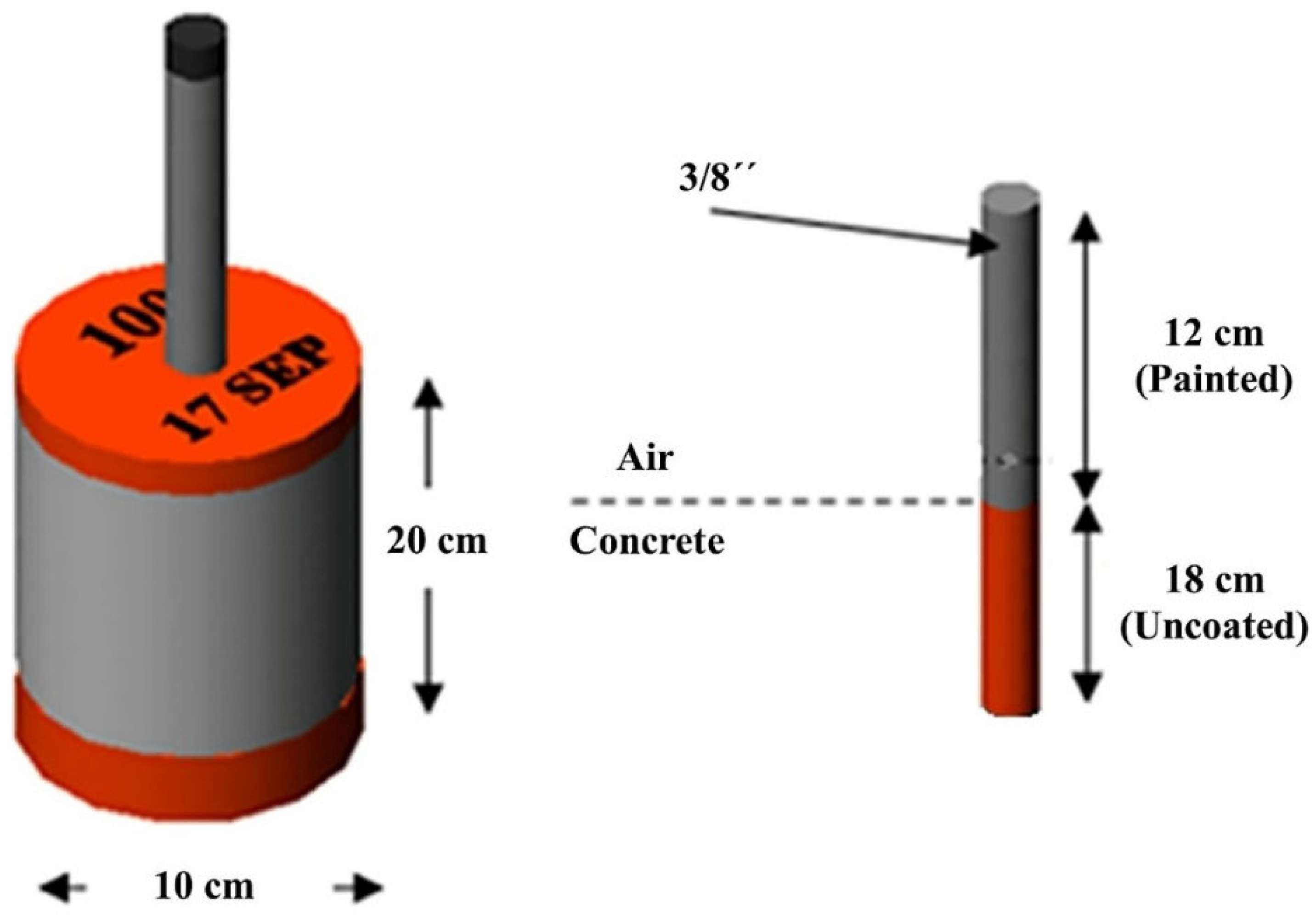
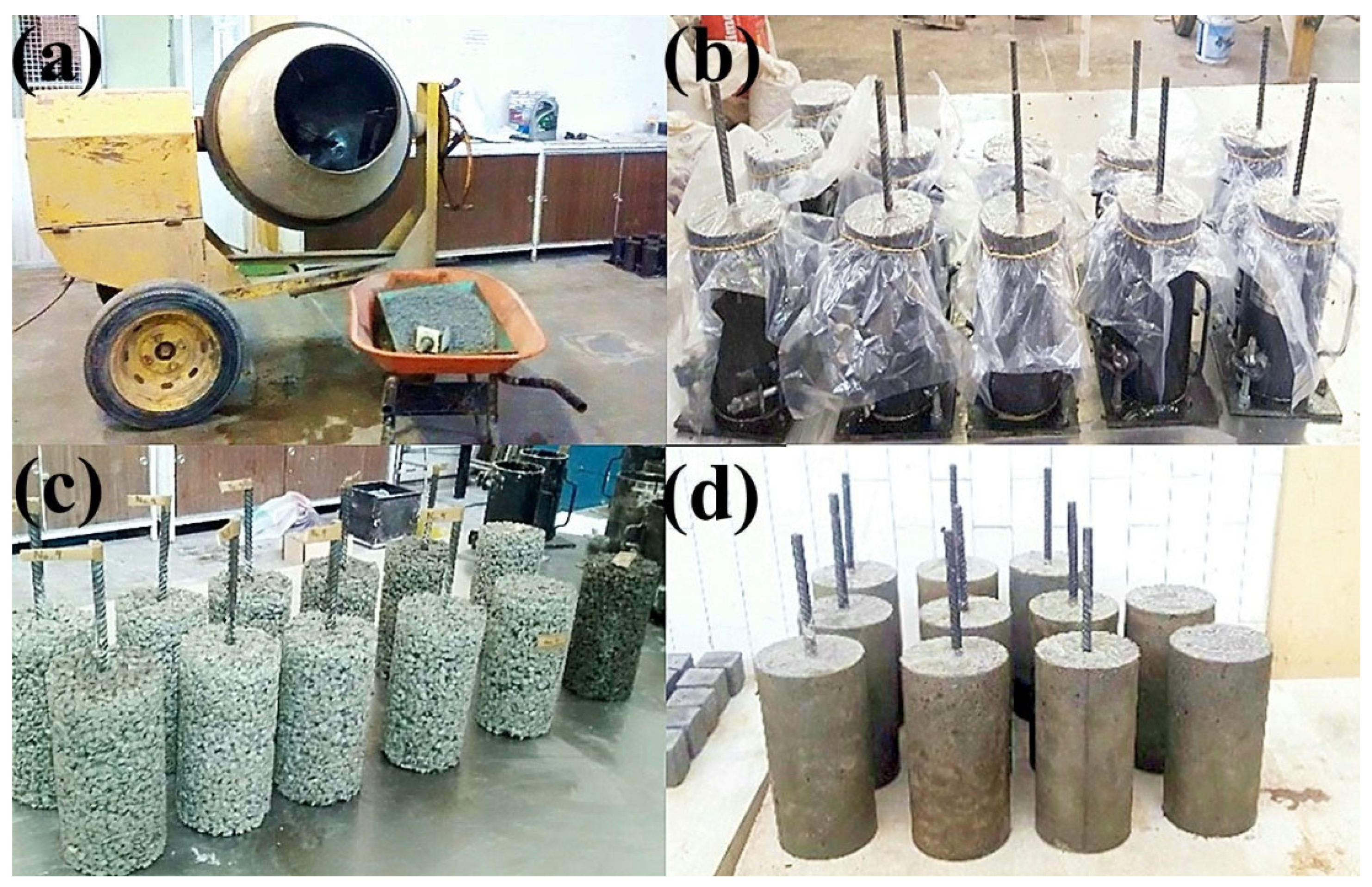
2.1. Design and Elaboration of Concrete Specimens

The cement used to make the mixture was Type I composite Portland cement, produced according to ASTM C150-07 [36]. For the production of specimens, a thick aggregate was used with granulometries of No. 4 (4.75 mm), No. 3/8″ (9.525 mm), No. 1/2″ (12.7 mm), No. 5/8″ (15.875 mm), and No. 3/4″ (19.05 mm). The conventional concrete absorbed 2.41% and had a compacted dry density of 2360 kg/m3, as specified in the ASTM C33/C33M-18 standard [37].
The mixing water for the concrete complied with ASTM C1602/C1602M-22 [38]. As specified in ASTM C494/C494M [39], a fluidizing water-reducing SIKA brand (SikaCem 40b) additive was used for mixtures of permeable concrete with aggregates with various granulometries.
The materials were used to manufacture conventional concrete, and a fine aggregate was added. Specimens were prepared according to the ASTM C 33 standard [37]. A fine aggregate with a fineness modulus of 2.68, a mass density of 2.645 kg/m3, and absorption of 4.1% was used.
A sand graduation in which one or two particle sizes predominate was avoided, resulting in a high vacuum content and requiring a higher amount of cement–sand paste to produce a workable mixture. Maximum workability was achieved when the separate sizes of sand formed a smooth curve within the granulometric limits. Figure 1 shows the materials used to make conventional concrete.
The elaboration of samples for electrochemical tests consisted of seven groups of cylindrical specimens (six groups of permeable concrete and one of conventional concrete). The cylinders were 10 cm in diameter with a height of 20 cm. The rod was No. 3 (3/8″), with a length of 30 cm and with 18 cm embedded in the concrete. The steel was protected using epoxy paint in the concrete–steel interface zone. Figure 2 shows the geometry of the specimens, of which six groups of permeable concrete (No.4, 1/4″, 3/8″, 1/2″, 5/8″, and 3/4″) were used for permeability tests.
Permeable concrete with six different aggregate sizes and conventional concrete specimens with 3/4″ crushed gravel were manufactured. Table 1 shows the corresponding dosages.

2.2. Preparation of Cylindrical Specimens of Permeable Concrete

The specimens were prepared in accordance with the ASTM C31/C31M-23 standard [40], which outlines the procedures needed to prepare and cure cylindrical concrete specimens. The molds were filled into three layers of an equal volume. Enough concrete was added in the last layer so that the mold was full after compaction. For the compaction of permeable concrete, each layer was compacted with 25 rod penetrations which were distributed in a spiral shape ending in the center [40].
The permeable and conventional concrete mixtures were made according to the NMX-C-159-ONNCCE-2016 standard [41]. The concrete was prepared in a tilting drum concrete mixer (Figure 3a) which was previously moistened. The coarse aggregate and about half of the water were placed inside and left to stir at about 20 rpm for 1 min. Then, cement, sand, additive, and the rest of the water were placed inside, leaving the mixture to stir at about 20 rpm for 3 min. Subsequently, it was left to stand for 3 min and covered with a bag to prevent water evaporation. Then, the revolver was turned back on for 2 min to better integrate the materials.
The specimens were removed from the molds between 18 h and 24 h after molding (Figure 3b). They were labeled using nomenclature based on their characteristics for identification. The specimens were placed in a curing room, where they remained for 28 days [41], Figure 3c,d. The compressive strength was tested in a 30-ton “Tinius Olsen” universal machine.

2.3. Permeability Test

Permeability tests were performed to ensure that the manufactured permeable concrete specimens complied with the determined permeability coefficient in the 0.2 to 0.54 cm/s range. Figure 4 shows the variable-load permeameter used to determine the permeability coefficient according to the ACI 522 standard [16].

2.4. Electrochemical Tests

Corrosion tests were carried out as a reference for comparison after the preparation of the specimens by immersing them in a prepared solution of 5% sodium chloride to accelerate the corrosion process in the reinforcing steel (Figure 5a). The exposure of the specimens consisted of a cycle in which the specimens were immersed for three days in the aggressive medium and remained outside for the next four days. The process was repeated during the research period to study the steel’s behavior against the action of chloride [42].
This research aimed to obtain the corrosion rate through two electrochemical tests: Tafel curves and electrochemical frequency modulation (EFM). The electrochemical tests were conducted using a three-electrode electrochemical cell configuration and a potentiostat–galvanostat Gamry Reference 3000. The specimens exposed to the aggressive medium were studied and analyzed for 41 days to determine the behavior of the corrosion kinetics of the reinforcing steel.
To carry out the Tafel curve technique, a potential range of −200 mV to +200 mV was used as a parameter, with a scanning speed of 10 mV/min (Figure 5b). The electrochemical frequency modulation technique used a frequency A of 2 Hz, a frequency B of 5 Hz, an amplitude of 10 mV, and 4 cycles as parameters (Figure 5c). A steel rod in the specimen was used as the working electrode, a graphite bar was used as the counter electrode, and a Calomel electrode was used as a reference. Figure 5b,c show the electrochemical cell components used to conduct the tests.

3. Results and Discussion

Figure 6a shows the five types of pervious concrete specimens with different aggregate sizes and the two reference cylinders of conventional concrete in a row. Figure 6b directly compares the pervious (No. 4) and conventional concrete specimens. Figure 6c presents a detailed view of the steel rebar embedded in pervious concrete with a part uncovered by the concrete coarse aggregate. These images show a single half-piece of each type of specimen after the corrosion tests. It is possible to observe the conditions of the rebars, which were completely covered by corrosion residue in the form of red rust on the pervious concrete specimens. Comparatively, under the same corrosion test conditions, between the end of the concrete and the painted segment, only a small part on top of the conventional concrete specimens showed corrosion products.

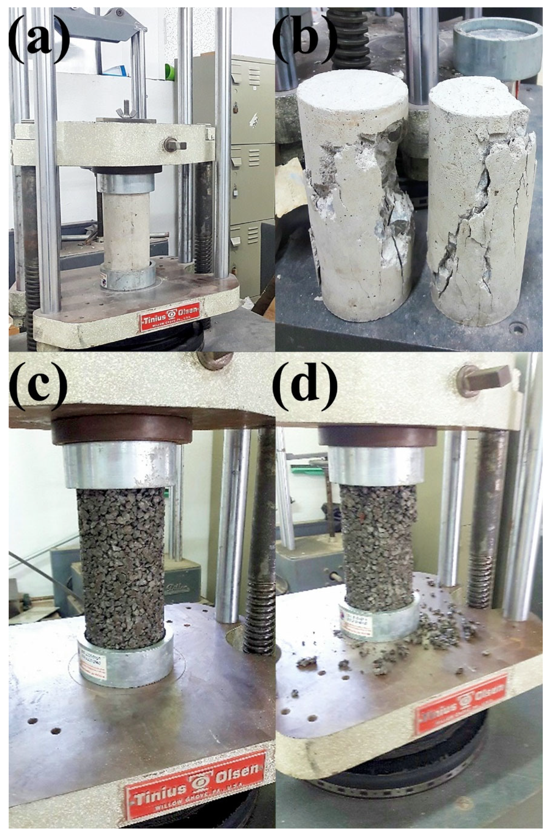
3.1. Simple Compressive Strength Tests

Simple compressive strength tests were performed to corroborate that the specified strength was met. Figure 7a–d shows the tested specimens. Table 2 shows the results obtained for two tests for each aggregate size. These were in accordance with other published works that indicate that compression strength is more related to voids and the binding material used [1,43,44]. The compressive strength values show that all the specimens were within the range of 65–82 kg/cm2, between M5- and M10-grade concrete. The conventional concrete used as a reference had a compressive strength of 180.3 kg/cm2, which was in the middle between M15- and M20-grade concrete. So, the results show that the obtained values were within the specified range. The tendency in the permeable concrete specimens was that the smaller the aggregate used, the higher the strength of the cylinder.

3.2. Permeability Coefficient Tests

Permeability tests were carried out using a variable-load permeameter to determine whether the permeable concrete specimens were within the range to be considered permeable. Table 3 shows the permeability coefficient values obtained in the test for two tests for each aggregate size. Each of the samples was tested at two different water level heights. The permeability coefficient of pervious concrete should be in the range of 0.2 to 0.54 cm/s. Therefore, when analyzing the values obtained, it can be noted that all specimens are within this range according to the ACI 522 [16]. The permeability of the specimen increases as the size of the inert aggregate increases, which is related to the structure formed in each specimen depending on the aggregate size.

3.3. Corrosion Currents of Steel Rebars in Pervious Concrete vs. Density

The density of each specimen analyzed was determined (Table 4). These values were compared with the corrosion values to observe the correlation between the concrete density and the behavior of the concrete with respect to steel corrosion.
Table 4 shows the weight and density of each of the cylindrical specimens. The volumes were measured by immersing the specimens in water. Concrete density is usually about 2400 kg/m3. The increase in the density of the pervious concrete, considering that the voids were not included, was attributed to the coarse aggregates, which were denser.
Table 4 also shows the icorr associated with variations in aggregate size measured using both techniques: electrochemical frequency modulation and Tafel curves. It is noticeable that corrosion increased as the aggregate size increased using both techniques. Also, icorr diminished as the concrete density decreased.

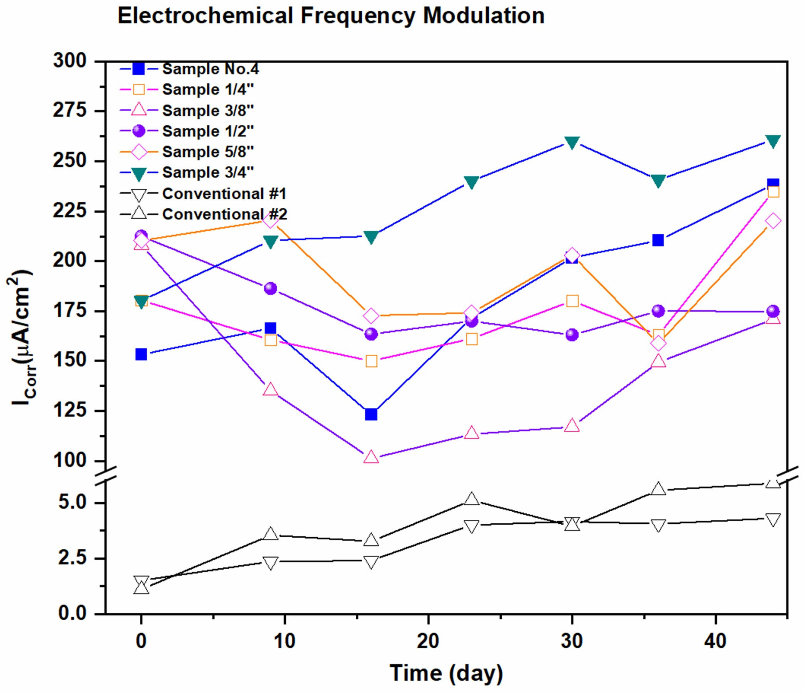
3.4. Electrochemical Frequency Modulation Tests for Corrosion Current Density icorr

EFM can offer a quick, repeatable, damage-free analysis that provides information on the corrosion potential, corrosion rate, and corrosion current. In this work, we verify the corrosion behavior of steel-reinforced concrete using EFM and Tafel curves. In the same way, conventional reinforced concrete specimens were evaluated.
Figure 8 shows the behavior of each of the reinforced permeable concrete samples in terms of corrosion density over time using the EFM technique. The specimens were analyzed weekly for 50 days. The corrosion current densities were much lower in reference specimens compared to permeable concrete specimens. So, the corrosion rate is higher. Also, the corrosion values increase from the first day of the analysis to the last day.
The conventional concrete specimens showed a corrosion current density two orders of magnitude lower than the previous ones. This fact is ascribed to the highly alkaline environment that passivates the rebars and differences in permeability.
When comparing this behavior between pervious concrete specimens with different aggregate sizes, it is observed that with larger aggregates, the corrosion current densities increased. The results of the electrochemical frequency modulation technique indicated an increase in the corrosion density of the reinforcing steel as the size of the inert aggregate increased. The specimen that presented lower corrosion density values was the one manufactured with the addition of the 3/4″ aggregate (the highest aggregate size), and the one that showed the highest corrosion values was No. 4 (the lowest aggregate size).

3.5. Tafel Curves Tests for Corrosion Current Density icorr

Figure 9 shows the corrosion density values of the permeable concrete specimens analyzed using the Tafel curve technique, comparing them against the granulometry used to manufacture each specimen. The specimens were analyzed weekly for 50 days.
The trend is similar, considering the differences between the two techniques, EFM and Tafel curves. The corrosion values increase from the first day of analysis to the last day. So, the results of the Tafel curve technique indicate a trend of the corrosion density of the reinforcing steel increasing as the inert aggregate size increases. On average, the corrosion density values were increasing. The specimens containing a coarse aggregate of 3/4″ had the highest values of icorr, and those containing the No.4 aggregate had the lowest values.
Table 5 shows the polarization resistance, measured using EFM and Tafel curves. As the time with active corrosion increases, the oxides generated on the steel rebars increase in surface coverage and thickness. This caused a slight reduction in the EFM measurements but a bigger change in the Tafel curves, which have longer measurement times. The references with conventional concrete significantly reduced the polarization resistances attributed to high internal alkalinity in the specimens that accelerated corrosion on the rebar surface.

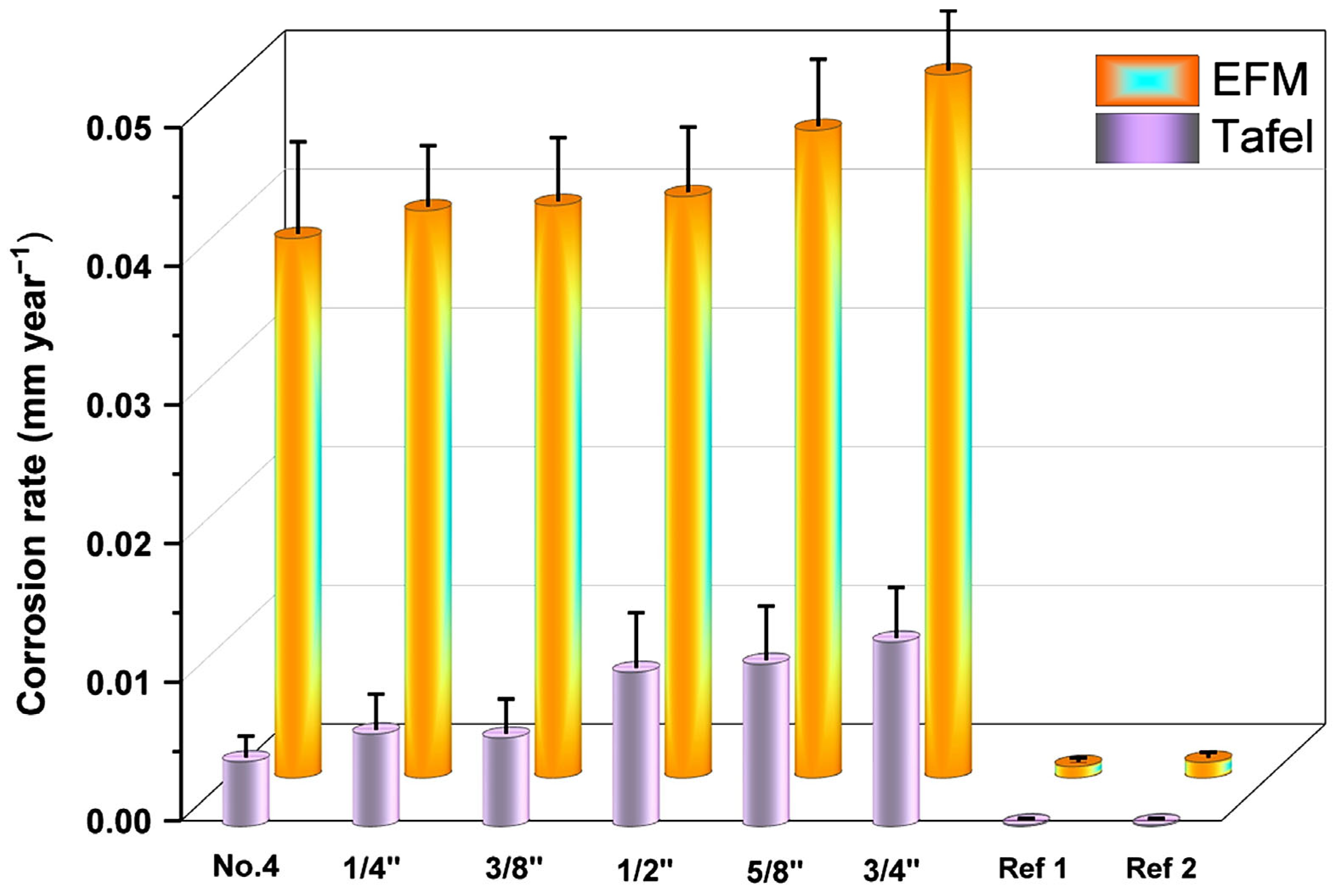
3.6. Corrosion Rates Analyzed by EFM and Tafel Curves

Figure 10 shows the corrosion rates of the reinforcing steel embedded in permeable concrete and conventional concrete. EFM and Tafel curve electrochemical techniques were used to evaluate the behavior.
The two techniques provide the same results in terms of corrosion rate. The corrosion rate increases in direct proportion to the aggregate size. The conventional concrete specimens presented corrosion rates well below those of the permeable concrete.
Considering that the corrosion rate of a steel rebar in seawater is about <0.1–1 mm year−1<, the results shown in Figure 10 are between one or two orders of magnitude lower. Contact with the surrounding material could reduce the exposed area of steel rebars in pervious concrete. The values shown in Figure 10 consider the Faraday formula, carbon steel density (0.00784 g/mm3), a 200 mm length, and a diameter of about 9.525 mm (3/8″). The standard deviation considers changes in the monitoring period.

4. Conclusions

Reinforced pervious concrete (RPC) specimens were prepared with five natural coarse aggregate granulometries.
  • The compressive strength values showed that all the specimens were within the range of 65–82 kg/cm2, between the M5 and M10 grades of concrete.
  • The physical aspects, such as moisture retention and how electrochemical tests are carried out when electrode communication is affected by the size of the coarse aggregate, were analyzed.
  • The permeability coefficients were between 0.31 and 0.52 cm/s, satisfying the ACI 522 standard.
  • The permeability of the specimen increases as the size of the inert aggregate increases, which is related to the structure formed in each specimen depending on the aggregate size.
  • It was observed that on average, the specimens of reinforced permeable concrete had higher corrosion rates, measured using the electrochemical techniques Tafel curves and electrochemical frequency modulation (EFM), than the specimens of conventional concrete that showed moderate corrosion.
  • The trend was an increase in corrosion density that was directly proportional to the increase in aggregate size. The specimen that presented lower values of corrosion density was the one manufactured with the addition of No. 4, and the one that showed the highest corrosion values was the specimen containing the 3/4″ aggregate.
  • The electrochemical frequency modulation (EFM) technique served not only to validate the Tafel test results and vice versa but to propose it as a viable alternative in corrosion studies for reinforced concrete and particularly for pervious concrete. This is the only work using such a technique with pervious concrete and one of the few using it for reinforced concrete.
There are no previous studies using reinforced pervious concrete (here, referred to by us as RFC) because it is not common to use it in such rigid structures. Nonetheless, whether alone or next to reinforced concrete, corrosion is an issue to investigate in this porous medium.

Author Contributions

Conceptualization, J.L.R.A. and J.d.J.P.B.; methodology, R.L.V., J.L.R.A., J.d.J.P.B., A.M.-R. and M.L.M.L.; validation, R.L.V., J.L.R.A., J.d.J.P.B. and A.M.-R.; formal analysis, R.L.V., J.L.R.A., J.d.J.P.B. and A.M.-R.; investigation, R.L.V., J.L.R.A., J.d.J.P.B. and A.M.-R.; resources, J.L.R.A. and J.d.J.P.B.; data curation, R.L.V., J.L.R.A. and J.d.J.P.B.; writing—original draft preparation, R.L.V., J.L.R.A., J.d.J.P.B., A.M.-R. and M.L.M.L.; writing—review and editing, R.L.V., J.L.R.A., J.d.J.P.B., A.M.-R. and M.L.M.L.; visualization, R.L.V., J.L.R.A., J.d.J.P.B. and A.M.-R.; supervision, R.L.V., J.L.R.A., J.d.J.P.B. and A.M.-R.; project administration, J.L.R.A. and J.d.J.P.B.; funding acquisition, J.L.R.A. and J.d.J.P.B. All authors have read and agreed to the published version of the manuscript.

Funding

This research was funded by the National Council of Humanities, Science, and Technology CONAHCYT (México) through the Basic and/or Frontier Science Grant, grant no. 320114; the National Laboratory of Graphenic Materials, and the LANIAUTO are greatly appreciated. The authors appreciate support from the “Fondo Sectorial CONACYT-SENER Sustentabilidad Energética” through Grant 207450, and the “Centro Mexicano de Innovación en Energía Solar (CeMIESol)” as part of strategic project No. P62, “Prototype hybrid system of a supercritical CO2 expander with flat polycarbonate mirrors on automated heliostats”. Further, the authors thank The World Bank and SENER, who supported this work through grant No. 002/2017-PRODETES-PLATA.

Data Availability Statement

Data are contained within the article.

Acknowledgments

The authors thank CIDETEQ’s staff members for supporting the processes necessary for the projects and laboratory activities.

Conflicts of Interest

The authors declare no conflicts of interest.

References

  1. Ibrahim, A.; Mahmoud, E.; Yamin, M.; Patibandla, V.C. Experimental Study on Portland Cement Pervious Concrete Mechanical and Hydrological Properties. Constr. Build. Mater. 2014, 50, 524–529. [Google Scholar] [CrossRef]
  2. Toghroli, A.; Mehrabi, P.; Shariati, M.; Trung, N.T.; Jahandari, S.; Rasekh, H. Evaluating the Use of Recycled Concrete Aggregate and Pozzolanic Additives in Fiber-Reinforced Pervious Concrete with Industrial and Recycled Fibers. Constr. Build. Mater. 2020, 252, 118997. [Google Scholar] [CrossRef]
  3. Deepak, M.S.; Ramalingam, J.; Deepthi, B.R. M20–Grade Pervious Concrete Using Industrial Waste and Artificial Aggregates in Proportions. Mater. Today Proc. 2023. [Google Scholar] [CrossRef]
  4. Ćosić, K.; Korat, L.; Ducman, V.; Netinger, I. Influence of Aggregate Type and Size on Properties of Pervious Concrete. Constr. Build. Mater. 2015, 78, 69–76. [Google Scholar] [CrossRef]
  5. Sangthongtong, A.; Semvimol, N.; Rungratanaubon, T.; Duangmal, K.; Joyklad, P. Mechanical Properties of Pervious Recycled Aggregate Concrete Reinforced with Sackcloth Fibers (SF). Infrastructures 2023, 8, 38. [Google Scholar] [CrossRef]
  6. Brasileiro, K.P.; de Oliveira Nahime, B.; Lima, E.C.; Alves, M.M.; Ferreira, W.P.; dos Santos, I.S.; Bezerra Filho, C.P.; dos Reis, I.C. Influence of Recycled Aggregates and Silica Fume on the Performance of Pervious Concrete. J. Build. Eng. 2024, 82, 108347. [Google Scholar] [CrossRef]
  7. Nasser Eddine, Z.; Barraj, F.; Khatib, J.; Elkordi, A. From Waste to Resource: Utilizing Municipal Solid Waste Incineration Bottom Ash and Recycled Rubber in Pervious Concrete Pavement. Innov. Infrastruct. Solut. 2023, 8, 319. [Google Scholar] [CrossRef]
  8. Xie, H.-Z.; Li, L.G.; Ng, P.-L.; Liu, F. Effects of Solid Waste Reutilization on Performance of Pervious Concrete: A Review. Sustainability 2023, 15, 6105. [Google Scholar] [CrossRef]
  9. Furkan Ozel, B.; Sakallı, Ş.; Şahin, Y. The Effects of Aggregate and Fiber Characteristics on the Properties of Pervious Concrete. Constr. Build. Mater. 2022, 356, 129294. [Google Scholar] [CrossRef]
  10. Soto, F.R.C.; Bueno, J.d.J.P.; Mendoza López, M.L.; Chavela, M.H.; Ramos, M.E.P.; Manzano-Ramírez, A. Hydrothermal Evaluation of Vernacular Housing: Comparing Case Studies of Waste PET Bottles, Stone, and Adobe Houses. Buildings 2022, 12, 1162. [Google Scholar] [CrossRef]
  11. Chen, W.; Jin, R. Recycled Concrete for Nonstructural Applications. In Recycled Concrete; Elsevier: Amsterdam, The Netherlands, 2023; pp. 233–263. [Google Scholar]
  12. Chen, S.; Gao, Y.; Liang, C.; Raphael, D.; Shao, X. Research Progress on Pervious Recycled Aggregate Concrete. Bull. Chin. Ceram. Soc. 2020, 39, 150–156. [Google Scholar]
  13. Ma, Y.; You, Q.; Li, J.; Lu, C.; Yin, J.; Li, H.; Meng, W.; Liu, Z.; Wang, Y.; Gao, X.; et al. Study on the Use of CO2 to Strengthen Recycled Aggregates and Pervious Concrete. Constr. Build. Mater. 2024, 418, 135372. [Google Scholar] [CrossRef]
  14. ASTM C618-22; Standard Specification for Coal Fly Ash and Raw or Calcined Natural Pozzolan for Use in Concrete. ASTM: West Conshohocken, PA, USA, 2022.
  15. ASTM C1240-20; Standard Specification for Silica Fume Used in Cementitious Mixtures. ASTM: West Conshohocken, PA, USA, 2020.
  16. ACI PRC-522-23; Pervious Concrete—Report. American Concrete Institute Committee: Farmington Hills, MI, USA, 2023.
  17. Lee, M.-G.; Wang, Y.-C.; Wang, W.-C.; Hsieh, Y.-C. Abrasion and Maintenance of High-Strength Fiber-Reinforced Pervious Concrete. Buildings 2024, 14, 127. [Google Scholar] [CrossRef]
  18. Lee, M.-G.; Wang, W.-C.; Wang, Y.-C.; Hsieh, Y.-C.; Lin, Y.-C. Mechanical Properties of High-Strength Pervious Concrete with Steel Fiber or Glass Fiber. Buildings 2022, 12, 620. [Google Scholar] [CrossRef]
  19. Tamimi, A.; Tabsh, S.W.; El-Emam, M. Pervious Concrete Made with Recycled Coarse Aggregate and Reinforced with Date Palm Leaves Fibers. Materials 2023, 16, 7496. [Google Scholar] [CrossRef] [PubMed]
  20. Khankhaje, E.; Kim, T.; Jang, H.; Kim, C.-S.; Kim, J.; Rafieizonooz, M. Dataset on the Assessment of Pervious Concrete Containing Palm Oil Kernel Shell and Seashell in Heavy Metal Removal from Stormwater. Data Brief 2023, 50, 109570. [Google Scholar] [CrossRef]
  21. Li, J.; Xia, J.; Di Sarno, L.; Gong, G. Fiber Utilization in Pervious Concrete: Review on Manufacture and Properties. Constr. Build. Mater. 2023, 406, 133372. [Google Scholar] [CrossRef]
  22. Mohan, A.; Tom, A.; Sony, A.M.; Susan, R.; Nallanathel, M.; Dhanam, D.J. Partial Replacement of Cement with Cementitous Material in Permeable Concrete. Indian J. Environ. Prot. 2020, 40, 979–984. [Google Scholar]
  23. Arocho-Irizarry, M.; Segarra, R.; Diaz, V.M.; Hwang, S. Eco-Friendly Pervious Concrete Infrastructure for Stormwater Management and Bicycle Parking: A Case Study. Urban Water J. 2018, 15, 713–721. [Google Scholar] [CrossRef]
  24. Barbaccia, T.G. Fast, Dirty Water. Better Roads 2011, 81, 28–29. [Google Scholar]
  25. Khankhaje, E.; Kim, T.; Jang, H.; Rafieizonooz, M. Laboratory Evaluation of Heavy Metal Removal from Stormwater Runoff by Pervious Concrete Pavement Containing Seashell and Oil Palm Kernel Shell. Constr. Build. Mater. 2023, 400, 132648. [Google Scholar] [CrossRef]
  26. Chen, X.; Guo, Y.; Ding, S.; Zhang, H.; Xia, F.; Wang, J.; Zhou, M. Utilization of Red Mud in Geopolymer-Based Pervious Concrete with Function of Adsorption of Heavy Metal Ions. J. Clean. Prod. 2019, 207, 789–800. [Google Scholar] [CrossRef]
  27. He, N.; Zhang, L.; Zhuang, X.; Huang, H.; Yuan, Z. Preparation and Performance of Geopolymer Pervious Concrete in Red Mud Slag Base. In Advances in Frontier Research on Engineering Structures, Proceedings of the 7th International Conference on Civil Architecture and Structural Engineering (ICCASE 2023), Guangzhou, China, 14–16 April 2023; IOS Press: Amsterdam, The Netherlands, 2023. [Google Scholar]
  28. Gasca-Tirado, J.R.; Rubio-Ávalos, J.C.; Muñiz-Villarreal, M.S.; Manzano-Ramírez, A.; Reyes-Araiza, J.L.; Sampieri-Bulbarela, S.; Villaseñor-Mora, C.; Pérez-Bueno, J.J.; Apatiga, L.M.; Amigó Borrás, V. Effect of Porosity on the Absorbed, Reemitted and Transmitted Light by a Geopolymer Metakaolin Base. Mater. Lett. 2011, 65, 880–883. [Google Scholar] [CrossRef]
  29. Guzmán-Carrillo, H.R.; Gasca-Tirado, J.R.; López-Romero, J.M.; Apátiga-Castro Luis, M.; Rivera-Muñoz Eric, M.; Pineda-Piñón, J.; Pérez-Bueno, J.J.; Feregrino-Montes, C.; López-Naranjo, E.J.; Manzano-Ramírez, A. Encapsulation of Toxic Heavy Metals from Waste CRT Using Calcined Kaolin Base-Geopolymer. Mater. Chem. Phys. 2021, 257, 123745. [Google Scholar] [CrossRef]
  30. Zhou, G.; Luo, Y.; Xue, G. Study on Mechanical Properties of Metakaolin Based Geopolymer Pervious Concrete. E3S Web Conf. 2023, 439, 02006. [Google Scholar] [CrossRef]
  31. Reyez-Araiza, J.L.; Pineda-Piñón, J.; López-Romero, J.M.; Gasca-Tirado, J.R.; Arroyo Contreras, M.; Jáuregui Correa, J.C.; Apátiga-Castro, L.M.; Rivera-Muñoz, E.M.; Velazquez-Castillo, R.R.; Pérez Bueno, J.d.J.; et al. Thermal Energy Storage by the Encapsulation of Phase Change Materials in Building Elements—A Review. Materials 2021, 14, 1420. [Google Scholar] [CrossRef] [PubMed]
  32. Yan, L.; Yaghmour, E.; Scott, D.; Abu Qamar, M.I.; Fox, J.; Naito, C.; Neti, S.; Romero, C.E.; Sarunac, N.; Suleiman, M. Experimental Investigation of the Thermal Performance of Pervious Concrete Integrated with Phase Change Material for Dry Cooling Applications. Appl. Therm. Eng. 2024, 236, 121749. [Google Scholar] [CrossRef]
  33. Xu, C.; Yue, Z.; Jin, W. Research on Reinforcement Corrosion in Concrete by Using Electrochemical Frequency Modulation Technology. J. Chin. Soc. Corros. Prot. 2013, 33, 136–140. [Google Scholar]
  34. Aperador, W.; Ruiz, E.; Bautista-Ruiz, J. Corrosion Study of a Carbon Steel Immersed in Concrete Alternative by Electrochemical Frequency Modulation. Int. J. Chem. Sci. 2015, 13, 1137–1148. [Google Scholar]
  35. Zhang, X.; Loveday, D.; Krebs, A. Application of Electrochemical Techniques in the Corrosion Process of Rebar in the Concrete (I). NACE-Int. Corros. Conf. Ser. 2015, 2015, 113704. [Google Scholar]
  36. ASTM C150-07; Standard Specification for Portland Cement. ASTM: West Conshohocken, PA, USA, 2007.
  37. ASTM C33/C33M-18; Standard Specification for Concrete Aggregates. ASTM: West Conshohocken, PA, USA, 2018.
  38. ASTM C1602/C1602M-22; Standard Specification for Mixing Water Used in the Production of Hydraulic Cement Concrete. ASTM: West Conshohocken, PA, USA, 2022.
  39. ASTM C494/C494M-17; Standard Specification for Chemical Admixtures for Concrete. ASTM: West Conshohocken, PA, USA, 2017.
  40. ASTM C31/C31M-23; Standard Practice for Making and Curing Concrete Test Specimens in the Field. ASTM: West Conshohocken, PA, USA, 2023.
  41. Organismo Nacional de Normalización y Certificación de la Construcción y Edificación, S.C. NMX-C-159-ONNCCE-2016 Building Industry–Concrete–Making and Curing Test Specimens; ONNCCE: Mexico City, Mexico, 2016. [Google Scholar]
  42. Tittarelli, F.; Moriconi, G. The Effect of Silane-Based Hydrophobic Admixture on Corrosion of Reinforcing Steel in Concrete. Cem. Concr. Res. 2008, 38, 1354–1357. [Google Scholar] [CrossRef]
  43. Chandrappa, A.K.; Biligiri, K.P. Pervious Concrete as a Sustainable Pavement Material–Research Findings and Future Prospects: A State-of-the-Art Review. Constr. Build. Mater. 2016, 111, 262–274. [Google Scholar] [CrossRef]
  44. Lee, M.-G.; Wang, Y.-C.; Wang, W.-C.; Chien, H.-J.; Cheng, L.-C. Experimental Study on the Mechanical Properties of Reinforced Pervious Concrete. Buildings 2023, 13, 2880. [Google Scholar] [CrossRef]
Figure 1. The materials used for manufacturing concrete of the types (a) conventional and (b) pervious.
Infrastructures 09 00068 g001
Figure 2. Geometry of the specimen.
Infrastructures 09 00068 g002
Figure 3. (a) Concrete mixer, (b) concrete cylinder specimens during setting, and (c) pervious and (d) conventional concrete specimens after curing for 28 days.
Infrastructures 09 00068 g003
Figure 4. Variable-load permeameter.
Infrastructures 09 00068 g004
Figure 5. (a) Aqueous solution of NaCl 5 wt%. (b) Specimens of conventional and pervious concrete immersed in a saline solution. (c) Conventional and (d) pervious concrete cylinder test specimens immersed in saline solution. The configuration of the (1) working, (2) counter, and (3) reference electrodes.
Infrastructures 09 00068 g005
Figure 6. Condition of specimens cut in halves with reinforcing steel rods after corrosion tests. (a) From left to right, No.4, 1/4″, 3/8″, 1/2″, 5/8″, and 3/4″. (b) Specimens No. 4 and Ref. 1 for comparison. (c) Zoom-in of void leaving the rebar naked that was frequent in pervious concrete specimens.
Infrastructures 09 00068 g006
Figure 7. Images of cylindrical test tubes before and after tests with conventional concrete (a,b), and pervious concrete (c,d), respectively.
Infrastructures 09 00068 g007
Figure 8. Specimens of permeable concrete were tested using the electrochemical frequency modulation technique. Two references using conventional concrete are shown.
Infrastructures 09 00068 g008
Figure 9. Specimens of permeable concrete were tested using the Tafel curve technique. Two references using conventional concrete are shown.
Infrastructures 09 00068 g009
Figure 10. Corrosion rates obtained using EFM and Tafel curves.
Infrastructures 09 00068 g010
Table 1. Materials used to prepare conventional and pervious concretes.
Concrete TypeMaximum Aggregate SizeCement
(kg/m3)
Coarse Aggregate
(kg/m3)
Fine Aggregate
(kg/m3)
Water
(kg/m3)
Additive
(kg)
Conventional¾″3491095698224
PerviousNo. 43501638 1221.4
1/4″3451648 1201.38
3/8″3421653 1191.36
1/2″3341667 1171.33
5/8″3291676 1151.31
3/4″3231686 1131.29
Table 2. Simple compressive strength of the evaluated specimens.
AggregateCompressive Strength
[kg/cm2][N/mm2]Standard Deviation
No. 482.18.050.35
1/4″74.87.347.50
3/8″72.57.114.10
1/2″75.07.351.20
5/8″69.66.832.62
3/4″65.56.421.56
Ref. 1180.317.683.18
Table 3. Permeability coefficients of specimens.
AggregateHeight 1Height 2K Average (cm/s)
No. 40.320.310.31
1/4″0.360.350.36
3/8″0.380.400.39
1/2″0.360.360.36
5/8″0.490.510.50
3/4″0.500.540.52
Table 4. The weight and density of the cylindrical specimens. Final icorr vs. aggregate size, measured using EFM and Tafel curves.
Aggregate SizeEFM Icorr Final [μA/cm2]Tafel Icorr Final [μA/cm2]Weight
[kg]
Density
[kg/m3]
Moisture Content
[%]
Volume
[L]
Volume
[m3]
No.4238.4524.022.912694.441.751.080.0011
1/4″234.9845.292.882691.591.701.070.0011
3/8″170.923.842.802692.311.591.040.0010
1/2″174.8857.212.712683.171.551.010.0010
5/8″220.1345.12.702673.271.471.010.0010
3/4″260.7768.392.6726701.471.00.0010
Ref. 14.30.573.5423602.411.50.0015
Ref. 25.870.523.652354.842.151.550.0016
Table 5. Polarization resistance (Ω/cm2) was measured using EFM and Tafel curves.
AggregateEFMTafel
Rp InitialRp FinalRp InitialRp Final
No. 42.571.3093.2910.82
1/4″1.851.241047.58
3/8″1.821.2284.417.92
1/2″1.591.2141.954.55
5/8″1.511.0821.524.32
3/4″1.220.99712.793.80
Ref. 1173.3360.476500456.14
Ref. 2236.3644.298666.67448.26
Disclaimer/Publisher’s Note: The statements, opinions and data contained in all publications are solely those of the individual author(s) and contributor(s) and not of MDPI and/or the editor(s). MDPI and/or the editor(s) disclaim responsibility for any injury to people or property resulting from any ideas, methods, instructions or products referred to in the content.

