EMuS Muon Facility and Its Application in the Study of Magnetism
by
 ,
,
Jingyu Tang
1,2,3,* ,
,
Xiaojie Ni
4,
Xiaoyan Ma
5,
Huiqian Luo
5,
Yu Bao
1,2,
Ye Yuan
1,
Yuan Chen
1,
Yukai Chen
1,2,
Fanshui Deng
4,
Jingyu Dong
4,
Zhilong Hou
1,3,
Chunming Hu
1,2,
Hantao Jing
1,2,
Hao Liang
3,
Qili Mu
1,2,
Changjun Ning
1,2,
Ziwen Pan
4,
Yingpeng Song
1,6,
Jian Tang
7,
Nikos Vassilopoulos
1,
Haibo Wang
4,
Zongtai Xie
1,3,
Bangjiao Ye
4,
Guoqing Zhang
1,
Yingge Zhang
4,
Guang Zhao
1,
Wei Zhao
1,
Luping Zhou
1,5,
Donghui Zhu
1,2,
Zian Zhu
1,3 and
Miaoqing Zhuang
3add
Show full author list
1
Institute of High Energy Physics, Chinese Academy of Sciences, Beijing 100049, China
2
Dongguan Neutron Science Center, Dongguan 523803, China
3
University of Chinese Academy of Sciences, Beijing 100049, China
4
State Key Laboratory of Particle Detection and Electronics, University of Science and Technology of China, Hefei 230026, China
5
Beijing National Laboratory for Condensed Matter Physics, Institute of Physics, Chinese Academy of Sciences, Beijing 100190, China
6
National Synchrotron Radiation Laboratory, University of Science and Technology of China, Hefei 230029, China
7
School of Physics, Sun Yat-Sen University, Guangzhou 510275, China
*
Author to whom correspondence should be addressed.
Quantum Beam Sci. 2018, 2(4), 23; https://doi.org/10.3390/qubs2040023
Submission received: 20 July 2018
/
Revised: 20 August 2018
/
Accepted: 31 October 2018
/
Published: 7 November 2018
(This article belongs to the Special Issue Magnetic Materials and Magnetism)
Abstract
:A muon facility—EMuS (Experimental Muon Source)—at China Spallation Neutron Source (CSNS) has been studied since 2007. CSNS, which is designed to deliver a proton beam power of 100 kW at Phase-I, and will serve multidisciplinary research based on neutron scattering techniques, has just completed construction, and is ready to open to general users from September 2018. As an additional platform to CSNS, EMuS aims to provide different muon beams for multiple applications, among which, magnetism study by μSR techniques is a core part. By using innovative designs, such as a long target in conical shape situating in superconducting capture solenoids and forward collection method, EMuS can provide very intense muon beams with a proton beam of 5 kW and 1.6 GeV, from surface muons, decay muons, and high momentum muons to slow muons. In this article, the design aspects of EMuS, including general design, target station, muon beamlines, and μSR spectrometer, as well as prospects for applications on magnetism studies, will be reviewed.
1. Introduction
μSR is the abbreviation of muon spin relaxation, rotation, and resonance [1,2]. Since more than thirty years, μSR techniques have been employed as a powerful tool for condensed matter physics, especially on the study of magnetism, which has shown significant advantages over other kinds of techniques. With the development of new muon sources and advanced μSR spectrometers, they can play an even more important role in the future of magnetism studies. Due to the sensitivity of the muon to small magnetic field and the capability of probing both static and dynamic local field distribution, muons have been widely used in studying magnetic systems [3], including magnetically ordered systems, spin-glass system, frustrated spin systems, colossal magnetoresistance, low-dimensional systems, heavy fermion systems, superconductors, and others.
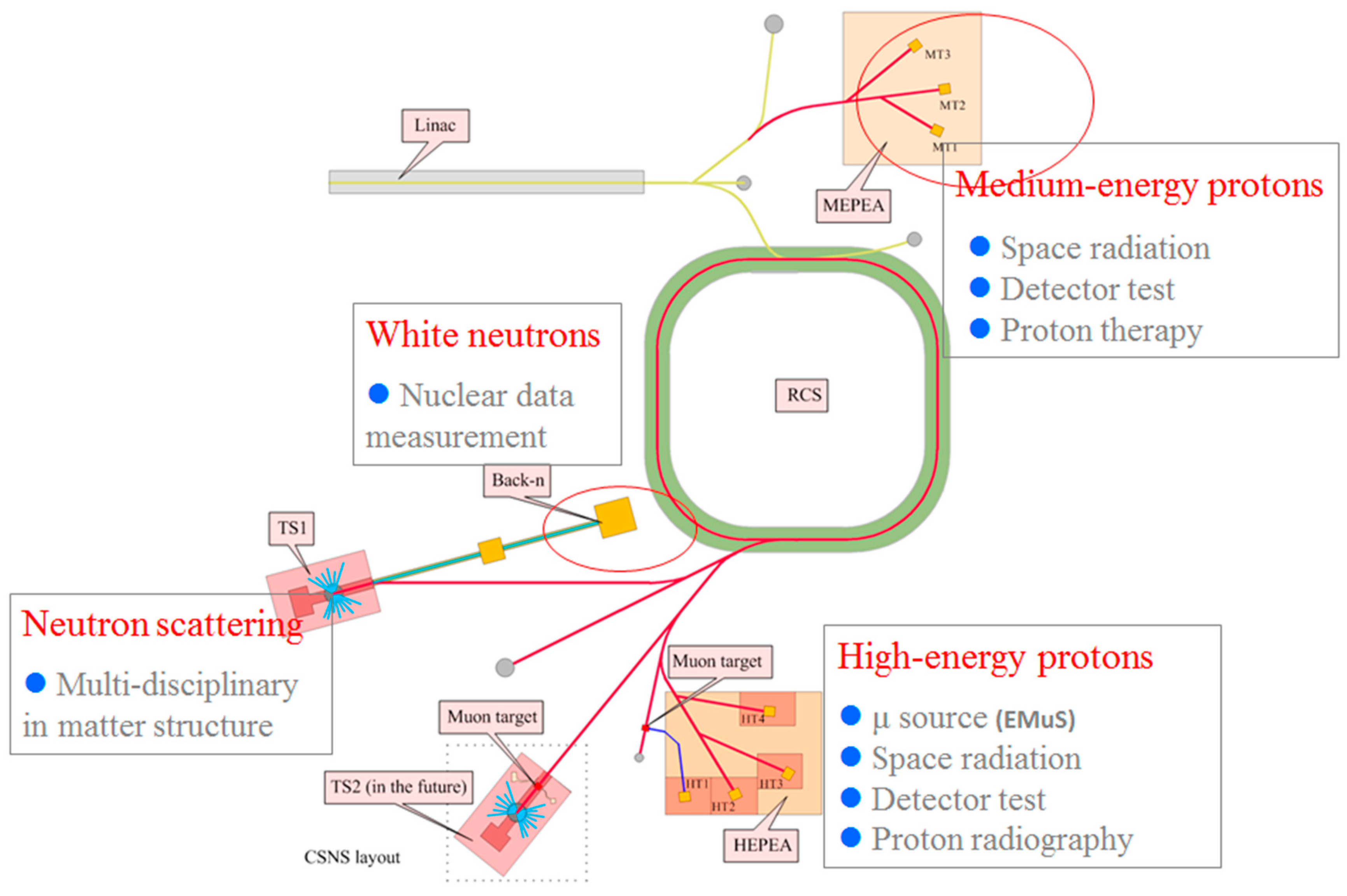
All the existing muon facilities (PSI/SμS [4], TRIUMF/CMMS [5], ISIS muon source [6] and J-PARC/MUSE [7]) are in the process of, or have plans to, upgrading the muon production and μSR spectrometers. A new muon facility RCNP/MuSIC is trying to develop μSR applications [8]. There are also proposals or projects to build new μSR facilities, such as EMuS (Experimental Muon Source) at China Spallation Neutron Source (CSNS) [9,10,11], and muon sources at ROAN [12] and Spallation Neutron Source (SNS). EMuS was proposed to be an extended platform at CSNS for muon science, see Figure 1, which will be a stand-alone facility and uses about 5% of the total proton beam power or 5 kW. μSR applications are certainly the core of the planned facility. Since 2007, preliminary design and R&D efforts have been carried out. With the recent completion of the CSNS project in March 2018, the construction of the EMuS facility becomes more realistic now. In this article, the design scheme of the EMuS facility, planned μSR spectrometers, and prospects in magnetism study will be presented.
2. EMuS Muon Beam Facility
2.1. General Design
The present planning is to build two muon facilities at CSNS, and the first one is a stand-alone facility or EMuS that will be built in the near future, whilst the second one will be related to the second target station (TS2) that hosts a spallation target and a muon target in tandem, but is planned on a longer term. EMuS is located in the so-called high-energy proton experimental area (HEPEA), where it hosts both muon beam applications and weak intensity proton applications, see Figure 2. For muon beam applications, the proton beam is split from the beam transport line (RTBT) directing to the spallation neutron target (TS1) and guided to the RTBT2 and HEPEA by a group of kickers that deflects one of the two bunches for every ten proton pulses. The CSNS accelerator facility provides a proton beam of 1.6 GeV in kinetic energy, and 100 kW in beam power with a repetition rate of 25 Hz at Phase-I, which is upgradable to 500 kW at Phase-II. The time structure of a proton pulse is that each bunch has a length of about 50 ns FWHM, and they are separated by 410 ns. In this way, the proton beam that drives the muon target has a nominal beam power of 5 kW, pulse length of 50 ns, and repetition rate of 2.5 Hz.
The scientific goals at EMuS include μSR applications using both surface and decay muons, particle and nuclear physics using both muon beam and neutrino beam, muon imaging using high-momentum muons, etc. This dictates that EMuS will work at different modes to provide different muon beams: a surface muon beam, a medium-momentum decay muon beam, and a high-momentum pion/muon beam. A slow or ultra-slow muon beam, via a muon moderator, will be added in the future by modifying the beam distribution system. To obtain as high as possible a muon intensity, EMuS adopts a target station design with a long graphite target coupled with a high-field capture superconducting solenoid. The optimization of the target station design favors a relatively lower magnetic field of about 1 T for surface muons, and higher field of 5 T for decay and high-momentum muons. Another major design feature is to extract muons or pions in the forward direction, which means that one has to separate the extracted muons or pions from the spent protons. All these will make the target station design much more complicated than in other designs.
The muon beam will be first transported to the so-called muon experimental area by a trunk beamline based on superconducting solenoids and a superferric dipole. Then, it is directed either to the surface muon beam area where three μSR spectrometers are planned, or to the decay muon beam area where other three types of spectrometers are planned. There are also other considerations: adding a thin target just in the front of the main muon target with a surface muon beam extracted in the vertical direction; adding a muon moderation section in the middle of the trunk beamline to provide slow muons.
2.2. Proton Beamline and Beam Dump
After the beam collimation that limits the acceptance from 350 πmm-mrad in RTBT to 150 πmm-mrad in the beamline to HEPEA, the proton beam is focused on the muon target with a small spot of about 5 mm in rms. A small proton beam spot is helpful for the collection of pions or muons. In order to separate the muon beam from the spent proton beam, an impinging angle of about 16 degrees to the target is used, which also means the tilt angle to the capture solenoids. As the proton beam is bent in the strong magnetic fields of the capture solenoids, a pair of steering magnets in front of the target is used to align the proton beam to the target in both the horizontal and vertical directions. The beam dump is designed to stand for 5 kW, but the calculated power deposition after bombarding the target is about 3.5 kW. However, since the magnetic field of the main capture solenoid is quite different for the surface muon mode and decay muon mode, the beam path of the spent protons is also quite different in the two working modes. This makes the dump design more complicated.
2.3. Muon Target Station
EMuS uses a long graphite target that situates in a high-field capture superconducting solenoid, and collects the muon or pion beam in the forward direction. The studies show that the capture field as high as possible is good for collecting decay muons, but a relatively lower field is preferred for collecting surface muons with high polarization. Other major factors influencing the target station design are the technical challenges and high cost of the high-field large aperture superconducting solenoids and the inner radiation shielding. The optimized design adopts 5 T for decay muon beams and 1 T for surface muon beam. It is also found that a conical target shape is also helpful in increasing the surface muon polarization and reducing the radiation heat in the target station. The present design uses a target of 300 mm in length, 45 mm in base radius. As in other solenoid-based muon capture system, it is important to have a field taper that gradually changes the peak magnetic field at the target location to a lower field in the beamline and converts transverse momentum into longitudinal momentum. At EMuS, three auxiliary capture solenoids with increasing apertures, but lower fields along the beam path, are used for the adiabatic matching, as shown in Figure 3.
The target and capture solenoids are being designed with an emphasis on μSR applications based on surface muons. With the muon capture method by solenoids, many so-called cloud muons, that are from the pions decayed in flight but at the proximity of the target, are also captured and transported together with surface muons. Even though the cloud muons have the same momentum as the surface muon, their polarizations are almost arbitrary. Therefore, the total beam polarization is significantly lower than a pure surface muon beam that has a polarization close to 100%. Thus, the figure of merit for the design is to have higher IP2 but with a constraint on the polarization P being larger than 50%, where I stands for muon beam intensity. A compromise between intensity and emittance is also considered, as those muons with a very large emittance contour are difficult to be focused into a small sample spot as required by most μSR experiments, e.g., φ30 mm in FWHM. However, a large-emittance high-intensity beam is considered useful for making slow muons that will be developed in the future.
Although heavy shielding with Tungsten material is inserted inside the solenoids, aluminum-based superconductors, similar to that used at COMET [13], should be used to resist the high-radiation dose rate in the target station.
2.4. Muon Transport Beamlines
After the field taper, two matching solenoids and one superferric-type dipole magnet are used to match the muon/pion beam and bend it by 30 degrees into the straight muon/pion beamline. Medium-momentum decay muons with high polarization and high-momentum muons are from the pions with a selected momentum bite that decay in the straight beamline section. To obtain high polarization for μSR applications, the medium-momentum decay muons are from backward pion decays. The high-momentum muons for applications, such as muon imaging, are from forward pion decays, and polarization is not required here. As the beam emittance is as large as 10–100 πmm-rad depending on different working modes, the focusing in the trunk beamline is based on superconducting solenoids. Periodic focusing is used for the most part of the straight section, but solenoids near the dipoles should have the ability to provide matchings. The momentum covering range for the trunk beamline is from 25 to 450 MeV/c. Figure 4 shows one design of the magnetic field pattern for transporting decay muons. In fact, the beamline transports a mixed beam of pions and muons, and pions continue to decay into muons along the beamline. It is feasible to employ the neutrinos from the pion decays in the straight section for low-energy neutrino cross-section measurements.
The branch beamlines to the surface muon spectrometers and the decay muon spectrometers are still under design, and each area will include as many as three spectrometers. For the beamlines to the surface muon spectrometers, both superconducting magnets and room-temperature magnets are under consideration; for the beamlines to the decay muon spectrometers, only superconducting magnets are under consideration. Table 1 summarizes the EMuS muon beam parameters in the trunk beamline, which are based on the Monte-Carlo simulations with G4beamline. We plan to use spatial splitting method by electrostatic fields to deliver surface muon beam to three μSR spectrometers simultaneously. A beam collimation will be used to provide usual beam spots of about 30 mm in FWHM at the samples, thus, a muon rate of 105 per second is expected for μSR applications. The high-intensity large-emittance surface muon beam in the trunk beamline is considered useful for future slow muon production. For decay muons, the situation will be similar for μSR applications, but higher intensity with larger emittance could be useful for other applications.
3. μSR Spectrometers
μSR is a technology to study the micro-mechanism and magnetism of condensed matter by measuring the time spectrum of the muon depolarization in a sample. It can be used in any form of material and under many experimental conditions, such as high temperature, high pressure, extremely low temperature, high external electromagnetic fields, light irradiation, radiofrequency field, and other conditions. For different experiments, different spectrometer types are needed. The most commonly used μSR methods are TF (transverse field) μSR, LF (longitudinal field) μSR, ZF (zero field) μSR, RF (radio frequency) μSR, and LE (low energy) μSR. They also depend on muon beam types, either a DC beam such as at PSI/SμS and TRIUMF/CMMS, or a pulsed beam such as at ISIS and J-PARC/MUSE. Recently, the LE-μSR technique by using moderated slow or ultra-slow muons is a hotspot worldwide, and has very powerful applications in surface physics. For pulsed muon beams, as beam intensity goes higher and higher, the count rate limitation from the conventional detection technique based on plastic scintillators and photomultipliers (PMT) becomes a serious problem. Very large detector arrays, e.g., a few thousands of detector units, especially those based on SiPM (silicon photomultiplier) detectors become very attractive [14,15].
At EMuS, different μSR spectrometers are planned, but will be built up gradually. To facilitate μSR experiments with high magnetic field, the muon bunch chopping method, as used at ISIS/HiFi spectrometer, might be considered [16]. A μSR spectrometer prototype based on PMTs is under development. At the same time, the design of a full-scale super μSR spectrometer, based on the SiPM technique, is also under way. Both spectrometers are presented here.
3.1. μSR Spectrometer Prototype for EMuS
A μSR spectrometer usually includes parts: a detector array, a sample chamber, and an external magnetic field system, electronics and data acquisition system, control system, running monitoring software, and data processing software. The detector array can detect the positrons emitted by the muons decayed in a sample. The sample chamber and external magnetic field system can provide different sample conditions and the required magnetic field.
As shown in Figure 5, the spectrometer prototype has an array of 128 channels (front and rear, each 64 channels), and each channel consists of a plastic scintillator, light guide, and a PMT. In the integrated design, it includes the following parts: beam pipe, sample chamber (sample holder, cryostat), detector system (scintillators, degraders, light guides, PMTs), and magnetic coils (longitudinal field, 0–300 Gauss).
After detailed simulations, we have completed the integrated design and determined the parameters of key parts that are shown in the Figure 5. Some modules of the prototype are being tested at the ISIS muon source in collaboration.
3.2. Design of a Super-μSR Spectrometer
As mentioned earlier, although a high-intensity pulsed muon source has the advantage of detection efficiency, the count rate is limited by the detector system based on PMT. It can be solved by increasing the detector units and reducing the solid angle of a single detector. However, conventional PMT has a large size, and is expensive and very sensitive to magnetic fields. The recently developed SiPM detector has the property being very efficient in detection, compact, and cheap, thus, is considered a good candidate for future large array μSR spectrometers. It is insensitive to magnetic fields, and can be used under strong magnetic field (~10 Tesla). PSI and J-PARC have already developed new μSR spectrometers based on SiPM [14,15].
At EMuS, the situation for the data pileup is even more challenging than in other pulsed muon sources, because it is driven by a proton beam of a quite low repetition rate of 2.5 Hz, and the peak muon flux is very high, due to the thick target situating in the high-field superconducting capture solenoid. In this case, a SiPM-based spectrometer is very attractive. Having much more detector units with SiPM technology, compared with most μSR spectrometers, will almost recover the disadvantage of the low repetition rate at EMuS. Furthermore, a much stricter energy degrader, to throw away low-energy positrons, is planned to increase the “asymmetry” parameter that is the key in μSR experiments. The present design of the so-called super-μSR spectrometer aims to have 2560 channels with a symmetrical double loop structure with 40 detector modules, see Figure 6. Each module consists of 64 plastic scintillators and 64 SiPMs, an ASIC-type integrated circuit and an FPGA development board. The magnetic field system consists of two sets of Helmholtz coils: a set of three-dimensional magnetic coils that mainly provides zero-field compensation to counteract the influence of the geomagnetic field, and a set of two-dimensional magnetic field coils that provides a longitudinal field of 0.5 T, and a transverse field of 0.03 T for measurements. The sample chamber uses a dilution refrigerator. The electronic system is different from traditional μSR spectrometers. The signals from the front-end go through the ASIC integrated circuit, and are treated in the FPGA board, then, the data is transferred to the Data Acquisition (DAQ) computer.
4. Prospects in Magnetism Study at EMuS
4.1. Comparison between μSR and Other Probes for Magnetism
The magnetism of materials mostly originates from the spin–spin interaction in the system that yields static magnetic orders under long-ranged spin correlation or dynamic magnetic excitations in the form of coherent spin waves or incoherent spin fluctuations. In order to study the magnetism in bulk materials, one should use a probe sensitive to the spin interaction or the local magnetic field; such probes can be neutrons, photons, electrons, muons, etc. For example, neutron scattering, where the spin-1/2 magnetic moment of neutron interacts with the electron spins, is an ideal tool to study both magnetic order and excitations from 0 to 1 eV under different resolutions. The recently developed resonant inelastic X-ray scattering (RIXS) is also a very powerful probe on high-energy spin excitations. μSR is a very important technique to study the magnetism for its sensitivity to the internal magnetic field and spin orders. In principle, μSR is similar to nuclear magnetic resonance (NMR) and electron spin resonance (ESR) [1]. While NMR uses nuclear moment to probe the local magnetic field and is highly selective on nucleus, μSR uses muon as an implanted guest in host materials, which breaks the limits on some specific materials in NMR research.
Figure 7 shows time windows for these typical experimental probes on magnetism, μSR covers time range from 1 ns to 10 ms (104 to 1012 Hz), which is between neutron scattering and NMR with overlapping. Since μSR is very sensitive to small magnetic moments as low as only 0.01 μB, and such tiny moments are nearly invisible in neutron powder diffraction or even neutron scattering on large-sized single crystals, it is a complementary tool to neutron scattering to study the existence of static magnetic moments. Although μSR is not able to give the detailed magnetic structure, due to its absence of momentum resolution, it can independently measure both the magnetic volume fraction and ordered moment, making it a unique and ideal real-space probe to investigate local magnetic fields in materials [17].
In the following sections, using recent topical examples of measurements made at other muon sources, we will show some potential μSR applications on magnetism at EMuS.
4.2. μSR Study on Magnetically Ordered Materials
Zero-field μSR (ZF-μSR) is an ideal technique to study the magnetic order in a material, since the magnitude of its oscillating signal is very sensitive to the directions of local fields. Specifically, ZF-μSR can distinguish the disordered spin distribution, short-range spin glass order, long-range spin density wave, as well as other magnetic textures, by giving the information about magnetic phase transition temperature, and ordered moment and volume.
The key of a μSR experiment is to analyze the time spectra of the muon-spin polarization by a correct relaxation function, and then to analyze the related parameters upon changing temperature or magnetic fields, to study the changes of the magnetic properties. Although different relaxation functions are used in particular experimental setups and samples as a basis, they include an exponential decay term, a Gaussian term, and a constant term, amongst others [17]. In Figure 8, the melanothallite, Cu2OCl2 is shown as an example, and the ZF-μSR spectra shows a clear muon spin precession signal below 65 K, which reflects a phase transition to a long-range magnetic order. The relaxation function is
where A1 and A2 refer to the asymmetry of muons stopped in the sample, σ and λ are relaxation rates, f is the muon spin precession frequency, is the initial phase, and AB is a constant background. Below 70 K, these parameters, A1, A2, σ, and f, experience a sudden change, which indicates the onset of magnetic order [18].
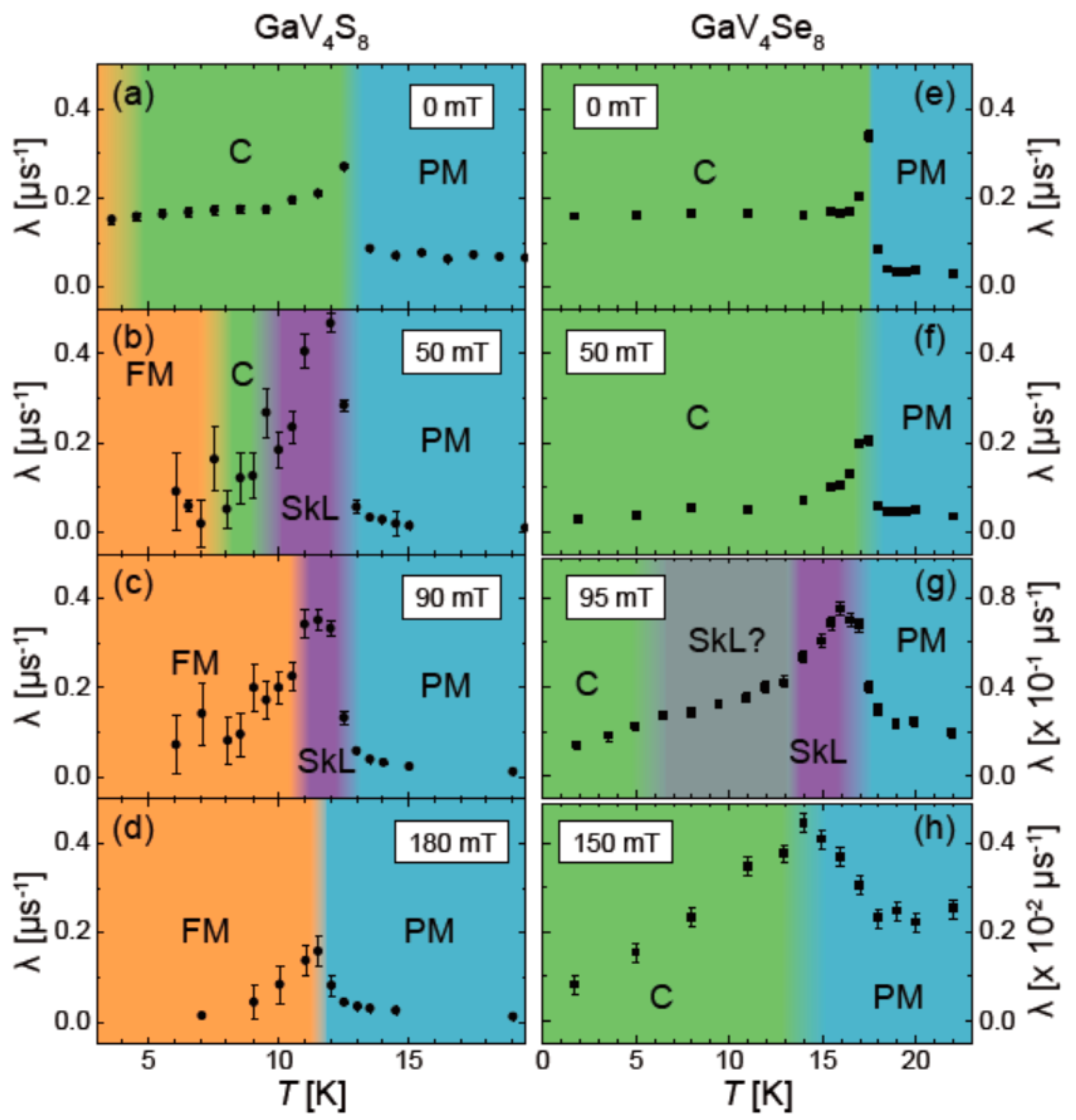
Other novel magnetic systems can be studied by μSR with different relaxation functions. For example, a spin density wave will give a sinusoidal modulation of the internal field and a Bessel function is used to fit the muon spin relaxation spectra [19,20]. μSR can be also used to identify skyrmions with a vortex-like spin pattern and special topological properties that comes from a helical state, which has been observed in many systems, such as MnSi, FeSi, and Fe1-xCox, etc. Another μSR study on GaV4S8-ySey system shows that GaV4Se8 and GaV4S8 have distinct magnetic ground states, where the latter one has an anomalous temperature-dependence of the local magnetic field, but both exhibit skyrmion-lattice phase in a 1–2 K-wide temperature range between 10 and 15 K (see Figure 9) [21]. Furthermore, transverse field μSR (TF-μSR) measurements of the skyrmion-lattice phase in Cu2OSeO3 also indicate that μSR can be utilized as a method for identifying these fascinating materials [22].
4.3. μSR Study on Quantum Spin Liquid Materials
In recent years, the search for quantum spin liquid (QSL) materials has attracted significant attention, due to their potential application in quantum information technologies, and the possible relevance to high-Tc superconductivity. The characteristic of spin liquid materials is that their spins are highly entangled, and remain disordered even down to zero temperature. μSR is an irreplaceable tool to search for such QSL states in a time window, which is nicely complementary to neutron and other probes (see Figure 7), and the best probe to clarify whether it is a short-ranged spin glass state or not. With μSR results, there are three possible lines of evidence for the existence of a spin liquid: (1) the ZF signals change continuously without showing spin precession at all temperatures even down to the mK range; (2) ZF-μSR shows a relaxation plateau feature at low temperature from a weak slowing down of the spin fluctuation, rather than the continuously increasing in a spin glass system; (3) the stretching exponent, β, gradually drops to a small value from high temperature to the base temperature. i.e., for QSL materials β is always above 1/2, but for a spin glass system, β is expected to drop to 1/3 at the spin freezing temperature [23,24]. Figure 10 shows YbMgGaO4 that supports the formation of a gapless U(1) QSL ground state in this triangular antiferromagnet [25]. Very recently, μSR is used to identify many newly discovered QSL candidates, e.g., a spin-1/2 material Cu3Zn(OH)6FBr with a gapped Z2 QSL state [26], the non-magnetically ordered system 6HB-Ba3NiSb2O9 [27], a possible antiferromagnetic liquid ground state in Ce2Sn2O7 [28].
4.4. μSR Studies on Superconducting Materials
Another important application of μSR at EMuS is the measurement of magnetic penetration depth (λ) on superconducting materials, which represents the superfluid density in the superconducting state. In type-II superconductors, the superconducting vortices usually are arranged in a triangular or square lattice under high magnetic field, where the distance between vortex cores is determined by the field: d~B−1/2. The first step is to extract the relationship between muon spin depolarization rate σ and the temperature at different magnetic-field distributions in the superconductor. Considering the broadening both from the randomly sampled field distribution of the vortex lattice and the randomly oriented nuclear magnetic moment in the sample, the effect of nuclear dipolar field σN is added to the σ, then we have
Here, σSC is the superconducting part of the Gaussian depolarization rate, which can be converted into the in-plane magnetic penetration depth λab via [29,30,31]:
where γμ/2π = 135.5 MHz/T is the muon gyromagnetic ratio, and Ф0 = 2.068 × 10⁻¹⁵ Wb is the magnetic flux quantum. By combining Equations (2) and (3), we can obtain the temperature dependence of the inverse-squared penetration depth . For highly anisotropic layered superconductors, such as the cuprate superconductors, λ is mainly determined by the in-plane penetration depth λab [32].
The magnetic penetration depth λ can give very important information about the pairing symmetry, since λ−2 is directly proportional to the superfluid density. For example, the temperature dependence of in the iron selenide superconductor FeSe0.85 (Tc ≈ 8.3 K) was found to be inconsistent with an isotropic s-wave symmetry of the superconducting gap [33]. TF and ZF-μSR experiments on the non-centrosymmetric compound, La7Ir3, have confirmed that time-reversal symmetry is broken in the superconducting state, since a spontaneous static or quasistatic magnetization has been clearly observed below Tc ≈ 8.3 K (Figure 11), thus, La7Ir3 is an unconventional superconductor with a dominant s-wave component [34].
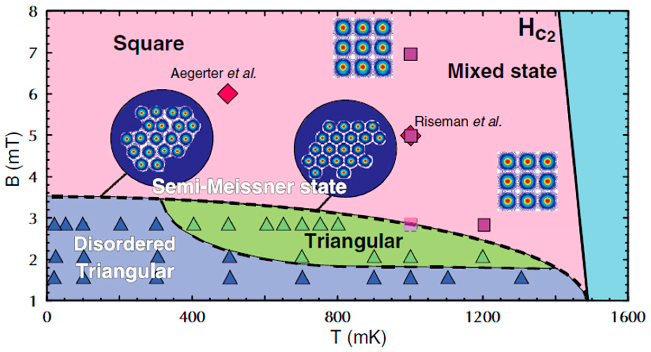
Since μSR is sensitive to the field induced by vortex, it can be easily used to distinguish the vortex lattice in the superconducting state. As shown in Figure 12, a phase-separated semi-Meissner state at low field and temperature was observed in Sr2RuO4, which is consistent with the nucleation of vortex clusters in type-1.5 scenarios, arising from the multiband nature of the superconductivity [35]. The analysis on the penetration depth of Sr2RuO4 suggests that it may be a p-wave superconductor, distinct from many other superconducting compounds.
5. Summary
A muon source facility at China Spallation Neutron Source has been studied, aiming to provide high-intensity muon beams for different applications, among them, the material magnetism studies with μSR techniques are the core part. The facility design features typical μSR spectrometers and prototyping, and several highly interesting directions in magnetism study are reviewed in this article. With the foreseen time schedule to build the facility in the next few years, and the high-standard design features, EMuS will provide an excellent facility for Chinese researchers and international users as well. In order to match the limited construction budget, we might obtain, in 2019, as the first step of the EMuS staging plan, a simplified version with a free target, and sideway collection to provide only surface muons to one μSR spectrometer is also under development. If everything goes well, we will have the first muon beam in China in 2022.
Author Contributions
J.T. (Jingyu Tang): leader of the EMuS study team, and coordinated the paper writing. X.N.: contributed to the muSR spectrometer writing. X.M. and H.L. (Huiqian Luo): contributed to the writing of μSR applications in magnetism. Y.Y.: coordinating the physics design. Y.B. and Y.Y.: contributed to the writing of the facility description. The team members at IHEP mainly contributed to the physics design, target station, conventional facilities: the team members at USTC mainly contributed to the design and prototyping of μSR spectrometers.
Funding
This research was funded jointly by National Natural Science Foundation of China (Grant numbers: 11527811, 11575217, 11235012, 11335009, 11611130165, 11674372), CAS Hundreds of Talents Program (Yu Bao), and the Youth Innovation Promotion Association of CAS (Huiqian Luo).
Acknowledgments
This work is jointly supported by the authors would like to thank some international experts for very useful discussions and technical support, especially I. Watanabe from RIKEN, A. Hillier, N. Rhodes and P. Biswas from ISIS, S. Mihara from KEK/J-PARC.
Conflicts of Interest
The authors declare no conflict of interest.
References
- Schenck, A. Muon Spin Rotation Spectroscopy; Adam Hilger: Bristol, UK, 1985. [Google Scholar]
- Yaouanc, A.; Dalmas de Réotier, P. Muon Spin Rotation, Relaxation and Resonance: Applications to Condensed Matter; Oxford University Press: Oxford, UK, 2011. [Google Scholar]
- de Réotier, P.D.; Yaouanc, A. Muon spin rotation and relaxation in magnetic materials. J. Phys. Condens. Matter 1997, 9, 9113–9166. [Google Scholar] [CrossRef] [Green Version]
- PSI-LMU: Laboratory for Muon Spin Spectroscopy. Available online: https://www.psi.ch/lmu/ (accessed on 1 November 2018).
- TIUMF Centre for Molecular and Materials Science. Available online: http://cmms.triumf.ca/ (accessed on 1 November 2018).
- ISIS Muons. Available online: https://www.isis.stfc.ac.uk/Pages/Muons.aspx (accessed on 1 November 2018).
- J-PARC/MUSE. Available online: http://www.j-parc.jp/MatLife/en/index.html (accessed on 1 November 2018).
- RCNP-MuSIC. Available online: http://www.rcnp.osaka-u.ac.jp/RCNPhome/music/ (accessed on 1 November 2018).
- Tang, J.Y.; Fu, S.N.; Wei, J. Characteristics and potential applications of the proton beams at the CSNS. J. Korean Phys. Soc. 2008, 52, 710–713. [Google Scholar] [CrossRef]
- Jing, H.T.; Meng, C.; Tang, J.Y.; Ye, B.J.; Sun, J.L. Production target and muon collection studies for an experimental muon source at CSNS. Nucl. Instrum. Meth. A 2012, 684, 109–116. [Google Scholar] [CrossRef]
- Xiao, R.; Liu, Y.-F.; Xu, W.-Z.; Ni, X.-J.; Pan, Z.-W.; Ye, B.-J. A new muon-pion collection and transport system design using superconducting solenoids based on CSNS. Chin. Phys. C 2016, 40, 057004. [Google Scholar] [CrossRef] [Green Version]
- Won, E. A proposal muon facility in RAON/Korea. In Proceedings of the International Symposium Science Explored by Ultra Slow Muon (USM2013), Matsue, Japan, 9–12 August 2013; p. 010110. [Google Scholar]
- Akhmetshin, R.; Akuma, K.; Aoki, M.; Appleby, R.B.; Arimoto, Y.; Begaturia, Y.; Bertsche, W.; Bondar, A.; Bryman, D.; Chiladze, B.; et al. COMET Phase-1 Technical Design Report; KEK Report 2015-1. 2015. Available online: http://comet.kek.jp/Documents.html (accessed on 1 November 2018).
- Stoykov, A.; Scheuermann, R.; Sedlak, K.; Shiroka, T.; Zhuk, V. First experience with G-APDs in instrumentation. Nucl. Instrum. Methods Phys. Res. Sect. A Accel. Spectrom. Detect. Assoc. Equip. 2009, 610, 374–377. [Google Scholar] [CrossRef]
- Higemoto, W.; Kadono, R.; Kawamura, N.; Koda, A.; Kojima, K.M.; Makimura, S.; Matoba, S.; Miyake, Y.; Shimomura, K.; Strasser, P. Materials and life science experimental facility at the Japan proton accelerator research complex IV: The Muon facility. Quantum Beam Sci. 2017, 1, 11. [Google Scholar] [CrossRef]
- Salman, Z.; Baker, P.J.; Blundell, S.J.; Cottrell, S.P.; Giblin, S.R.; Hillier, A.D.; Holsman, B.H.; King, P.J.C.; Lancaster, T.; Lord, J.S.; et al. HiFi-A new high field muon spectrometer at ISIS. Phys. B Condens. Matter 2009, 404, 978–981. [Google Scholar] [CrossRef]
- Blundell, S.J. Spin-polarized muons in condensed matter physics. Contemp. Phys. 1999, 40, 175–192. [Google Scholar] [CrossRef] [Green Version]
- Kawashima, K.; Okabe, H.; Suzuki, K.; Kuroiwa, S.; Akimitsu, J.; Sato, K.H.; Koda, A.; Kadono, R. Antiferromagnetic ordering in Cu2OCl2 studied by the muon spin rotation/relaxation technique. J. Phys. Condens. Matter 2007, 19, 145275. [Google Scholar] [CrossRef]
- Major, J.; Mundy, J.; Schmolz, M.; Seeger, A.; Doring, K.P. Zero-field muon spin rotation in monocrystalline chromium. Hyp. Int. 1986, 31, 259. [Google Scholar] [CrossRef]
- Amato, A. Heavy-fermion systems studied by μSR technique. Rev. Mod. Phys. 1997, 69, 1119–1179. [Google Scholar] [CrossRef]
- Müller, H.; Kockelmann, W.; Johrendt, D. The magnetic structure and electronic ground states of mott insulators GeV4S8 and GaV4S8. Chem. Matter 2006, 18, 2174–2180. [Google Scholar] [CrossRef]
- Lancaster, T.; Williams, R.C.; Thomas, I.O.; Xiao, F.L.; Pratt, F.L.; Blundell, S.J.; Loudon, J.C.; Hesjedal, T.; Clarck, S.J.; Hatton, P.D.; et al. Transverse field muon-spin rotation signature of the skyrmion-lattice phase in Cu2OSeO3. Phys. Rev. B 2015, 91, 224408. [Google Scholar] [CrossRef]
- Ogielski, A.T. Dynamics of three-dimensional Ising spin glasses in thermal equilibrium. Phys. Rev. B 1985, 32, 7384. [Google Scholar] [CrossRef]
- Brown, P.; Smith, G.N.; Hernández, E.P.; James, C.; Eastoe, J.; Nunes, W.C.; Settens, C.M.; Hatton, T.A.; Baker, P.J. Magnetic surfactants as molecular based-magnets with spin glass-like properties. J. Phys. Condens. Matter 2016, 28, 176002. [Google Scholar] [CrossRef] [PubMed] [Green Version]
- Li, Y.; Adroja, D.; Biswas, P.K.; Baker, P.J.; Zhang, Q.; Liu, J.; Tsirlin, A.A.; Gegenwart, P.; Zhang, Q. Muon spin relaxation evidence for the U(1) quantum spin-liquid ground state in the triangular antiferromagnet YbMgGaO4. Phys. Rev. Lett. 2016, 117, 097201. [Google Scholar] [CrossRef] [PubMed]
- Wei, Y.; Feng, Z.; Lohstroh, W.; Dela Cruz, C.; Yi, F.; Ding, Z.F.; Zhang, J.; Tan, C.; Shu, L.; Wang, Y.-C.; et al. Evidence for a Z2 topological ordered quantum spin liquid in a kagome-lattice antiferromagnet. arXiv, 2017; arXiv:1710.02991. [Google Scholar]
- Quilliam, J.A.; Bert, F.; Manseau, C.; Darie, C.; Guillot/Deudon, C.; Payen, C.; Baines, C.; Amato, A.; Mendels, P. Gapless quantum spin liquid ground state in the spin-1 antiferromagnet 6HB-Ba3NiSb2O9. Phys. Rev. B 2016, 93, 214432. [Google Scholar] [CrossRef]
- Sibille, R.; Lhotel, E.; Pomjakushin, V.; Baines, C.; Fennell, T.; Kenzelmann, M. Candidate quantum spin liquid in the Ce3+ pyrochlore stannate Ce2Sn2O7. Phys. Rev. Lett. 2015, 115, 097202. [Google Scholar] [CrossRef] [PubMed]
- Khasanov, R.; Guguchia, Z. Probing the multi gap behavior within ‘11’ and ‘122’ families of iron based superconductors: The muon-spin rotation studies. Supercond. Sci. Technol. 2015, 28, 034003. [Google Scholar] [CrossRef]
- Fesenko, V.I.; Gorbunov, V.N.; Smilga, V.P. Analytical properties of muon polarization spectra in type-II superconductors and experimental data interpretation for mono- and polycrystalline HTSCs. Phys. C Supercond. 1991, 176, 551–558. [Google Scholar] [CrossRef]
- Brandt, E.H. Flux distribution and penetration depth measured by muon spin rotation in high-Tc superconductors. Phys. Rev. B 1988, 37, 2349–2352. [Google Scholar] [CrossRef]
- Zimmermann, P.; Keller, H.; Lee, S.L.; Savić, I.M.; Warden, M.; Zech, D.; Cubitt, R.; Forgan, E.M.; Kaldis, E.; Karpinski, J.; et al. Muon-spin-rotation studies of the temperature dependence of the magnetic penetration depth in the YBa2Cu3Ox family and related compounds. Phys. Rev. B 1995, 52, 541–552. [Google Scholar] [CrossRef]
- Khasanov, R.; Conder, K.; Pomjakushina, E.; Amato, A.; Baines, C.; Bukowski, Z.; Karpinski, J.; Katrych, S.; Klauss, H.-H.; Luetkens, H.; et al. Evidence of nodeless superconductivity in FeSe0.85 from a muon-spin-rotation study of the in-plane magnetic penetration depth. Phys. Rev. B 2008, 78, 220510. [Google Scholar] [CrossRef]
- Barker, J.A.T.; Singh, D.; Thamizhavel, A.; Hiller, A.D.; Lees, M.R.; Balakrishnan, G.; Paul, D.M.; Singh, R.P. Unconventional superconductivity in La7Ir3 revealed by muon spin relaxation: Introducing a new family of noncentrosymmetric superconductor that breaks time-reversal symmetry. Phys. Rev. Lett. 2015, 115, 267001. [Google Scholar] [CrossRef] [PubMed]
- Ray, S.J.; Gibbs, A.S.; Bending, S.J.; Curran, P.J.; Babaev, E.; Baines, C.; Mackenzie, A.P.; Lee, S.L. Muon-spin rotation measurements of the vortex state in Sr2RuO4: Type-1.5 superconductivity, vortex clustering, and a crossover from a triangular to a square vortex lattice. Phys. Rev. B 2014, 89, 094504. [Google Scholar] [CrossRef]
Figure 1.
Schematic for multiple application platforms at China Spallation Neutron Source (CSNS).

Figure 2.
Layout schematic for the high-energy proton experimental area.

Figure 3.
Schematic for the Experimental Muon Source (EMuS) target station.

Figure 4.
One magnetic field pattern along the trunk beamline for decay muons. Z = 0 corresponds to the entrance of the capture solenoid, and the target center is at the peak field of 5 T. The rectangular shape field drops in the red curve are bending magnets.
Figure 4.
One magnetic field pattern along the trunk beamline for decay muons. Z = 0 corresponds to the entrance of the capture solenoid, and the target center is at the peak field of 5 T. The rectangular shape field drops in the red curve are bending magnets.

Figure 5.
Schematic diagram for the integrated design of the μSR spectrometer prototype.

Figure 6.
Design concept for a super-μSR spectrometer.

Figure 7.
Time windows for several experimental probes on magnetism.

Figure 8.
Temperature dependence of fit parameters from ZF-μSR of Cu2OCl2 [18].
Figure 8.
Temperature dependence of fit parameters from ZF-μSR of Cu2OCl2 [18].

Figure 9.
Results of fitting zero field (ZF) and longitudinal field (LF) data for GaV4Se8 (a–d for different field levels) and GaV4S8 (e–h for different field levels) [21].
Figure 9.
Results of fitting zero field (ZF) and longitudinal field (LF) data for GaV4Se8 (a–d for different field levels) and GaV4S8 (e–h for different field levels) [21].

Figure 10.
Temperature dependence of the muon spin relaxation rates from zero field measurements and from the bulk static susceptibilities measured in an applied field of 0.01 T for YbMgGaO4 [25].
Figure 10.
Temperature dependence of the muon spin relaxation rates from zero field measurements and from the bulk static susceptibilities measured in an applied field of 0.01 T for YbMgGaO4 [25].

Figure 11.
(a) Temperature dependence of the TF-μSR spin-depolarization rate for La7Ir3 in different fields; (b) field dependence of the muon spin-depolarization rate at different temperatures; (c) temperature dependence of the inverse magnetic penetration depth squared [34].
Figure 11.
(a) Temperature dependence of the TF-μSR spin-depolarization rate for La7Ir3 in different fields; (b) field dependence of the muon spin-depolarization rate at different temperatures; (c) temperature dependence of the inverse magnetic penetration depth squared [34].

Figure 12.
A vortex phase diagram of Sr2RuO4 [35].
Figure 12.
A vortex phase diagram of Sr2RuO4 [35].


Table 1.
Summary of the EMuS muon beam parameters.
| Surface Muon | Decay Muon (High Polarization) | Decay Muon (High Momentum) | |
|---|---|---|---|
| Momentum (MeV/c) | 28 | 130 | 450 |
| Intensity (1 × 10⁶/s) | 43 | 100 | 50 |
| Polarization (%) | −77 | 68 | −30 |
| Δp/p (±%) | 12 | 9 | 10 |
| Emittance (πmm-rad) | 30 | 30 | 30 |
© 2018 by the authors. Licensee MDPI, Basel, Switzerland. This article is an open access article distributed under the terms and conditions of the Creative Commons Attribution (CC BY) license (http://creativecommons.org/licenses/by/4.0/).
Share and Cite
MDPI and ACS Style
Tang, J.; Ni, X.; Ma, X.; Luo, H.; Bao, Y.; Yuan, Y.; Chen, Y.; Chen, Y.; Deng, F.; Dong, J.; et al. EMuS Muon Facility and Its Application in the Study of Magnetism. Quantum Beam Sci. 2018, 2, 23. https://doi.org/10.3390/qubs2040023
AMA Style
Tang J, Ni X, Ma X, Luo H, Bao Y, Yuan Y, Chen Y, Chen Y, Deng F, Dong J, et al. EMuS Muon Facility and Its Application in the Study of Magnetism. Quantum Beam Science. 2018; 2(4):23. https://doi.org/10.3390/qubs2040023
Chicago/Turabian StyleTang, Jingyu, Xiaojie Ni, Xiaoyan Ma, Huiqian Luo, Yu Bao, Ye Yuan, Yuan Chen, Yukai Chen, Fanshui Deng, Jingyu Dong, and et al. 2018. "EMuS Muon Facility and Its Application in the Study of Magnetism" Quantum Beam Science 2, no. 4: 23. https://doi.org/10.3390/qubs2040023