
Effect of Process Parameters on Laser Powder Bed Fusion of Al-Sn Miscibility Gap Alloy


Department of Mechanical Engineering, Politecnico di Milano, Via La Masa 1, 20156 Milan, Italy
*
Authors to whom correspondence should be addressed.
Quantum Beam Sci. 2022, 6(2), 17; https://doi.org/10.3390/qubs6020017
Submission received: 28 March 2022
/
Revised: 20 April 2022
/
Accepted: 22 April 2022
/
Published: 25 April 2022
(This article belongs to the Special Issue Laser Assisted Manufacturing)
Abstract
:Al-Sn binary system is a miscibility gap alloy consisting of an Al-rich phase and a Sn-rich phase. This system is traditionally applied in bearings and more recently found application as form-stable phase change material (PCM) exploiting solid-liquid phase transition of Sn. A careful choice of production process is required to avoid macro-segregation of the two phases, which have different densities and melting temperatures. In the present study, the additive manufacturing process known as laser powder bed fusion (LPBF) was applied to an Al-Sn alloy with 20% volume of Sn, as a rapid solidification process. The effect of process parameters on microstructure and hardness was evaluated. Moreover, feasibility and stability with thermal cycles of a lattice structure of the same alloy were experimentally investigated. An Al-Sn lattice structure could be used as container for a lower melting organic PCM (e.g., a paraffin or a fatty acid), providing high thermal diffusivity thanks to the metallic network and a “safety system” reducing thermal diffusivity if the system temperature overcomes Sn melting temperature. Even if focused on Al-Sn to be applied in thermal management systems, the study offers a contribution in view of the optimization of manufacturing processes locally involving high solidification rates and reheat cycles in other miscibility gap alloys (e.g., Fe-Cu) with similar thermal or structural applications.
1. Introduction
Al-Sn binary systems are miscibility gap alloys (MGAs), i.e., they consist of two phases which are immiscible in solid state. In more detail, the two phases are almost pure Al and pure Sn. Thanks to their anti-wear performance, these alloys have been widely used in bearings [1]. More recently, they were studied as form-stable phase change materials (PCMs), specifically composite materials in which the Sn-rich active phase undergoing a solid/liquid transition is mixed to a high-melting Al-rich phase [2,3]. The latter can provide structural properties as well as modify thermal and other characteristics of the material. PCMs can be used in thermal energy applications since they can store the latent heat associated to an endothermic transition (e.g., melting) and release it when the transition is reversed (e.g., solidification). Furthermore, the material can be used to limit the maximum temperature of the system, at least within certain heat input limits.
Simple casting of molten MGAs results in both micro-segregation of the lower melting phase at grain boundaries of the high-melting one, and in macro-segregation of the low-melting phase in the last solidifying regions [4]. Contrarily, powder metallurgy and rapid solidification processes can result in a more homogeneous and finer phase distribution. Powder metallurgy has been applied either for Al-Sn based bearing materials by Zhu et al. [1,5,6,7] and for metallic Al-Sn based PCMs by Confalonieri et al. [3,8,9] and Sugo et al. [2]. With these kind of techniques, the homogeneous and fine phase distribution is provided through compaction and sintering of homogeneous powder blends, which are not, or only partially, melted, thus preventing macro-segregation of low-melting phase. On the other hand, rapid solidification methods involve complete melting of base material in form of powders or homogeneous ingots. The following solidification with high cooling rate entraps low-melting phase in the network created by primary nucleation of high-melting one. Several techniques are reported in literature to obtain fast solidification of Al-Sn based alloys, like laser alloying (Zhai et al. [4], Makhatha et al. [10]), high-velocity oxyfuel (Marrocco et al. [11]), and melt spinning (Lucchetta et al. [12], Kim and Cantor [13], Zhang W. et al. [14], and Zhang Z. et al. [15]). Confalonieri and Gariboldi [16] studied the possibility of using laser powder bed fusion (LPBF) as rapid solidification process in which a blend of Al and Sn powders is locally melted through a pulse laser. In laser-based powder bed systems, a powder layer is first applied on a building platform, then a laser melts it locally according to the input 3D model, and finally the platform is lowered; the cycle is repeated until the part is fully built, embedded in the powder bed [17]. Confalonieri and Gariboldi [16] observed that the extremely fine microstructure obtained for Al-Sn alloy with LPBF was similar to the finest microstructures obtained from compressed ball-milled powders [8,9]. This microstructure can provide high hardness and wear resistance [1], as well as interesting thermal properties. In more detail, a fine distribution of Al-Sn phases results in a relatively fast thermal storage followed by a more gradual heat release in a wide range of temperatures, thus reducing thermal stresses during cooling [3,9]. The advantage of using LPBF is, therefore, the possibility to couple a suitable microstructure for conventional Al-Sn based MGA applications in bearings or as PCMs, with the design freedom typical of an additive manufacturing technique compared to the limitations of powder metallurgy involving compression and sintering.
The present paper aims to study the effect of LPBF process parameters on the properties of Al-Sn alloy with Al/Sn ratio equal to 80/20, in view of its application in thermal storage and thermal management devices. Differently from typical LPBF applications, the classical target of reducing discontinuities like pores and cracks is flanked by the need to control phase distribution and to have a microstructurally stable material over several thermal cycles. Once the relationship between parameters and microstructure is established, the material designer can select the proper parameters according to the features required by the specific application. The results of this study can also be helpful to produce other MGAs through LPBF. For example, Fe-Cu based MGAs are investigated for their higher thermal conductivity with respect to steels and high strength [18,19], as well as for the possibility of using them as PCMs [2].
In addition to simple parallelepiped samples, a 3D lattice structure was produced to prove the feasibility to print a complex structure. The microstructure of the materials was investigated by electron microscopy. Material hardness was measured by Vickers tests. The thermal stability was evaluated by experimenting possible operating conditions for PCMs.
Lattice structures could be used as a container for a low-melting PCM [20,21]. This kind of hybrid system contains two PCM systems: a low-melting one, such as paraffin (melting temperature range: 6–108 °C [22]) or fatty acids (with melting temperature in a slightly narrow melting range), which stores latent heat in the temperature range of interest; and a high-melting one (e.g., Al-Sn), which enhances thermal diffusivity to the overall system thanks to the metallic network [23] and also can act as “safety system” by reducing thermal diffusivity upon its phase transition if the system temperature increases too much. The presence of the low-melting PCM, with high wettability on Al alloys could also avoid the formation of Sn particles at the material surface.
2. Materials and Methods
Commercially pure Al (ECKA Granules Germany GmbH, Fürth, Germany) and pure Sn (STAGNO 106, Metalpolveri S.r.l., Gussago (BS), Italy) powders were mixed to obtain a blend with 20% volume of Sn, corresponding to about 40% in mass. Both powders had high purity (>99.7% mass). Al powder had grain size lower than 45 µm, while Sn powder contained also coarser particles (>106 μm: 0.1%, >45 μm: 15–45%, <45 μm: 55–85%). SEM micrographs of powders are shown in Figure 1. Before the mixing processes, powders were sieved separately with a −63 µm mesh, to remove coarse particles and agglomerates. Then, they were blended in a tumbler mixer (Adler T-0) with about 1/3 of empty space in the jar, for 1 h at 20 rpm at room temperature.
LPBF process was carried out using a pulsed laser Renishaw (Wotton-under-Edge, United Kingdom) AM 250 system equipped with a Reduced Build Volume apparatus (powder bed 90 mm × 90 mm). Using a pulsed laser, powders are melted by discrete and partially overlapped laser spots, which are exposed to the radiation for a given time (exposure time) [24]. The process was carried out in protective Ar atmosphere to reduce contamination from oxygen (oxygen content < 1000 ppm). A meander scanning strategy was applied and the scanning direction was rotated by 67° after each layer completion. The selected process parameters were in the range of typical values for Al alloys [24]. Layer thickness (25 µm), laser power (200 W), and exposure time (160 µs) were the same for all the samples. On the other hand, different values for hatch distances (dh), i.e., the distance between the parallel adjacent scanned tracks, and point distance (dp), i.e., distance between two neighbor points exposed to the pulsed laser, were selected, as reported in Table 1.
Volumetric energy density (also referred as specific energy, and expressed in J/mm3) can be evaluated according to Equation (1), by approximating the scanning speed (v) as the ratio between point distance (dp) and exposure time (texp):
where P is the laser power, dh is the hatch distance, and l is the layer thickness. Calculated values for each set of parameters are in Table 1. Two batches of samples were produced (A-I1, L-N); powders for the second batch were dried in a desiccator with silica for about 24 h before LPBF.
Specimens are parallelepipeds, with size 8 × 8 × 4 mm3 for batch 1 (A-I1) and 10 × 8 × 4 mm3 for batch 2 (L-N). Furthermore, a longer sample (40 × 9 × 5 mm3), called I2, that was cut in smaller pieces for testing, and two lattice structures (with geometry shown in Figure 2 and produced with combination of parameters I) were added to the specimens of batch 2.
Characterization of parallelepiped samples consisted of the analysis of microstructure and hardness. Samples were sectioned, mounted, and ground with abrasive papers followed by polishing with diamond suspensions down to 1 µm. For microstructural characterization, both Optical Microscopy (OM, Eclipse LV150NL, Nikon, Tokyo, Japan) and Scanning Electron Microscopy (SEM, EVO 50, Zeiss, Jena, Germany) were used to evaluate materials features at different scale levels. Micrographs were analyzed using ImageJ software [25], measuring area fraction of pores, pore features, and crack density. In more detail, analyzed pore features are [26,27,28]:
- Equivalent diameter (∅eq), i.e., calculated diameter of a circle with the same area as the pore;
- Circularity, i.e., 4·π·area/perimeter2, which tends to 1 if the particle is round and smooth, and tends to 0 if it has irregular surface and/or elongated shape;
- Solidity, i.e., ratio between pore area and the minimum convex area that can cover the pore, which tends towards 1 if the pore has a convex shape, and tends towards zero if the boundary is irregular.
Crack density (dcracks) is the average distance between cracks measured on a section parallel to building direction at low magnification.
Vickers microhardness tests were done on samples built on the diagonal of process parameter matrix shown in Table 1 (A, E, I, N). HV was measured along the sample direction parallel to the building direction, using a Future-tech FM-700 microhardness tester with a load of 4.91 N and a dwell time of 15 s. The test was repeated at least five times per sample choosing indentation points randomly on the sample surface to obtain an average value of hardness.
Analysis of lattice structures focused on evaluation of their behavior during thermal cycling reproducing operative conditions. Therefore, one of the lattice structures underwent 100 thermal cycles between 180 °C and 280 °C at a heating/cooling rate of ~27 °C/min, in protective Ar atmosphere to avoid oxidation of molten Sn. Photographs were taken before and after thermal cycles to observe possible changes.
3. Results
3.1. Low Magnification Analysis
Specimens printed with the two jobs are shown in Figure 3. The upper surface can have accumulated material at corners of the parallelepipeds, as pointed out by arrows for sample A in Figure 3. The accumulated material form peaks that are taller and wider as the VED increases, especially in samples from A to E. On the other hand, the samples with the lowest VED have an almost flat upper surface.
Optical micrographs of samples with the related process parameters are shown in Figure 4. At this relatively low magnification, Al and Sn phases are too fine to be distinguished; thus, specimens appear as consisting of a homogeneous grey metallic matrix with black areas corresponding to discontinuities, i.e., pores or cracks.
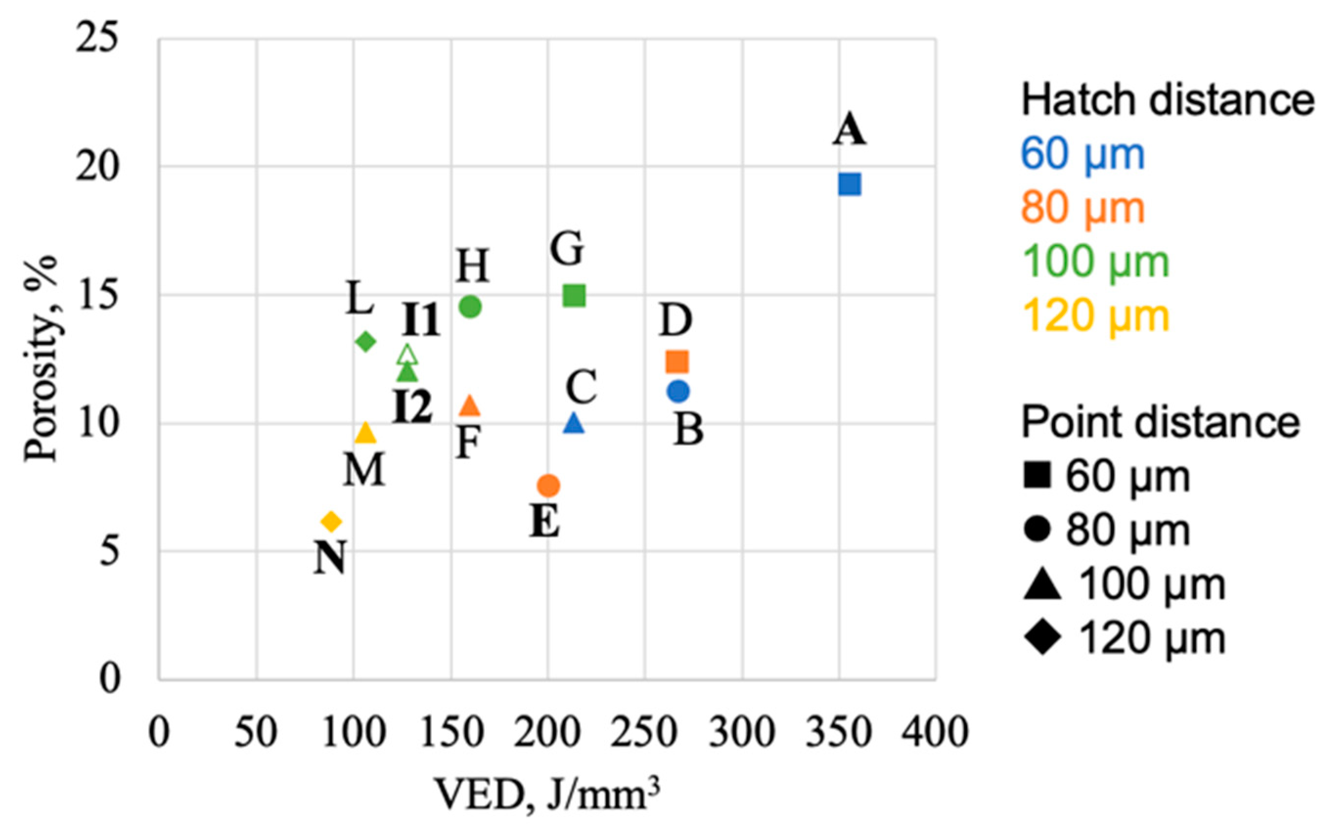
The average area fraction of pores (later on simply referred as porosity) as measured on OM micrographs ranges between 6% and 19%, with the highest value for the highest calculated VED (A) and the lowest ones for the lowest VED (N) and the central condition (E) (Figure 4 and Figure 5). The other specimens have porosity between 9% and 15%, but, as shown in Figure 5, there is not a clear trend, neither considering the calculated VED variation nor single parameter (hatch or point distance) variation. Average values of circularity and solidity equal to about 0.7 and 0.8, respectively (Figure 4), show that pores tend to have a spherical shape with smooth surface. Considering pore size, the average equivalent diameter is between 30 µm and 50 µm for all samples (Figure 4).
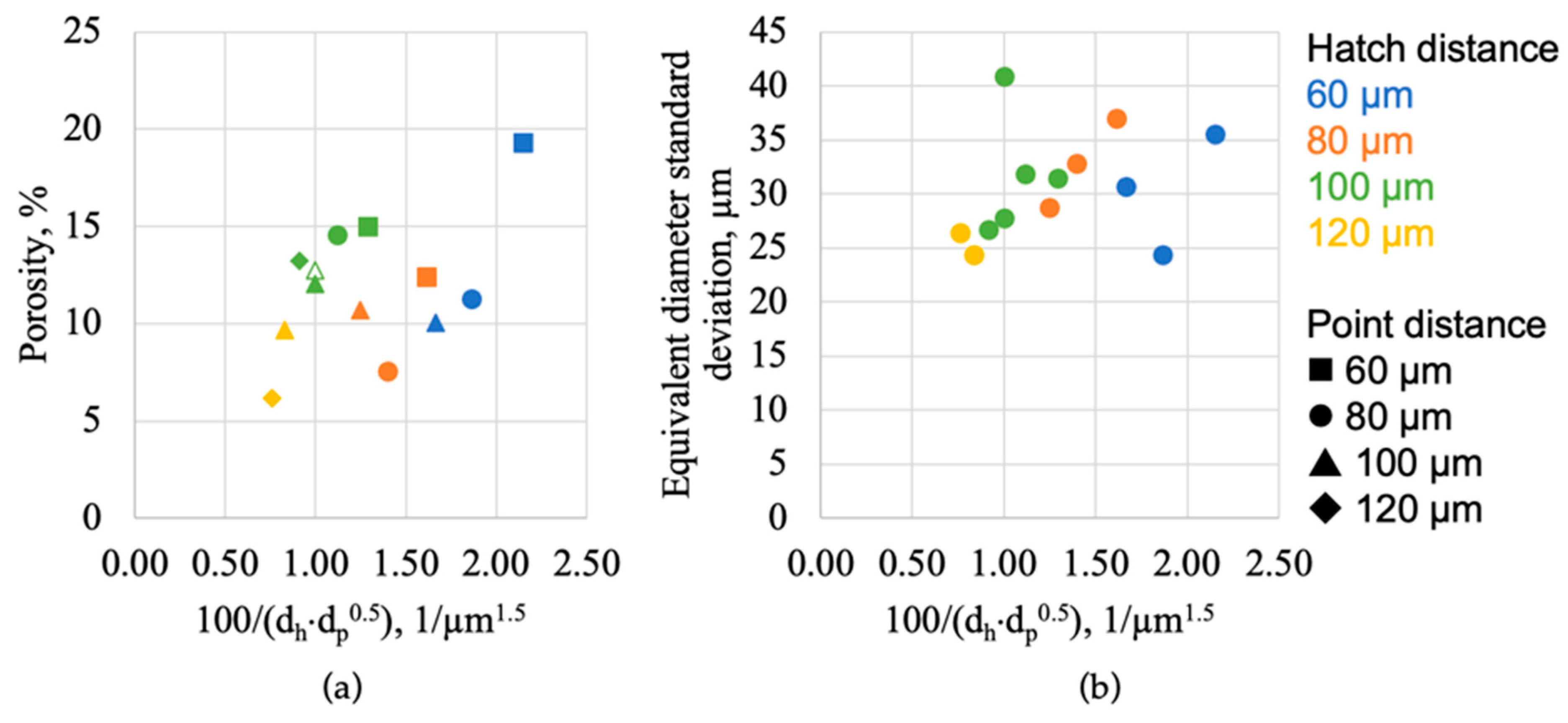
The most significant differences between specimens can be found in pore size distribution (Figure 6) and pore location in the plane parallel to build direction (Figure 4). In all the samples, most of pores (40–50%) have equivalent diameter lower than 50 µm and the percentage of pores per size decreases as equivalent diameter reduces (Figure 6a). As shown in Figure 6b, the standard deviation of equivalent diameter generally reduces with VED. The high standard deviation of specimen I1, here represented with open symbol, is related to the presence of interconnected big pores, considered as a single one by ImageJ software during particles analysis. Figure 6b suggests that high energy samples have a wider pore size range, between ~10 µm and ~100 µm, with respect to low energy ones, generally with bigger pores concentrated near the external surface and in correspondence with the upper surface peaks mentioned above (Figure 4). By reducing the VED, the standard deviation of equivalent diameter reduces as well, i.e., pore size distribution becomes narrower, and the arrangement of pores in the sample tends to be more homogeneous. Such features, that were observed on longitudinal sections of the specimens, have also been confirmed by analyses of transversal sections of samples. For sake of comparison, see OM image of samples A, E, I1, and N in Figure 7.
Vertical cracks (Figure 4) are generally parallel to the building direction, while cracks in sections perpendicular to building direction (Figure 7) tend to form a continuous network. In both sections, sample A (i.e., the one produced with the highest VED) displays few small cracks, concentrated especially in the region close to the building platform. On the other hand, the number of cracks increases as VED reduces. Considering crack position, they tend to concentrate in the middle of the sample at high energies, while they are more spread within the sample and interconnected in transverse direction at low energies. The minimum average distances between vertical cracks are 461 µm for sample D, while for the other samples this value ranges between 565 µm and 1232 µm or even higher. The range is compatible with the crack network distribution observed on transversal sections.
3.2. SEM Analysis
SEM micrographs of samples on diagonal of parameter matrix are shown in Figure 8, with increasing VED from A to N sample. Sn (bright contrast) and Al phases (dark contrast) can be distinguished in the SEM micrographs. The horizontal bands are formed by the grains grown between consequent layers in the production process; at low energies, Sn-rich zones are observed in these bands, highlighting the shape of molten pools. By decreasing energy, a finer structure is observed. The size of the Sn particles dispersed in Al phase is between ~2 µm and ~100 nm in sample A. In sample N, fine Sn films are formed along with Sn particles. The film is ~100 nm thick and the small particles are ~100 nm in size.
In all the samples, round-shape Sn particles with diameter of ~15 µm are observed (e.g., see sample N in Figure 8 and samples I and E in Figure 9). These particles seldomly show inner porosities (Figure 9b). Focusing on cracks (Figure 9), it is possible to notice that they can be partially or fully filled with Sn.
3.3. Vickers Microhardness
Results of Vickers microhardness measurements for samples on diagonal of parameters matrix are shown in Figure 10. Samples from the first batch (A, E, and I1) have hardness values of about 30 HV, while values for second-batch samples (I2 and N) are slightly above 40 HV.
3.4. Lattice Structures
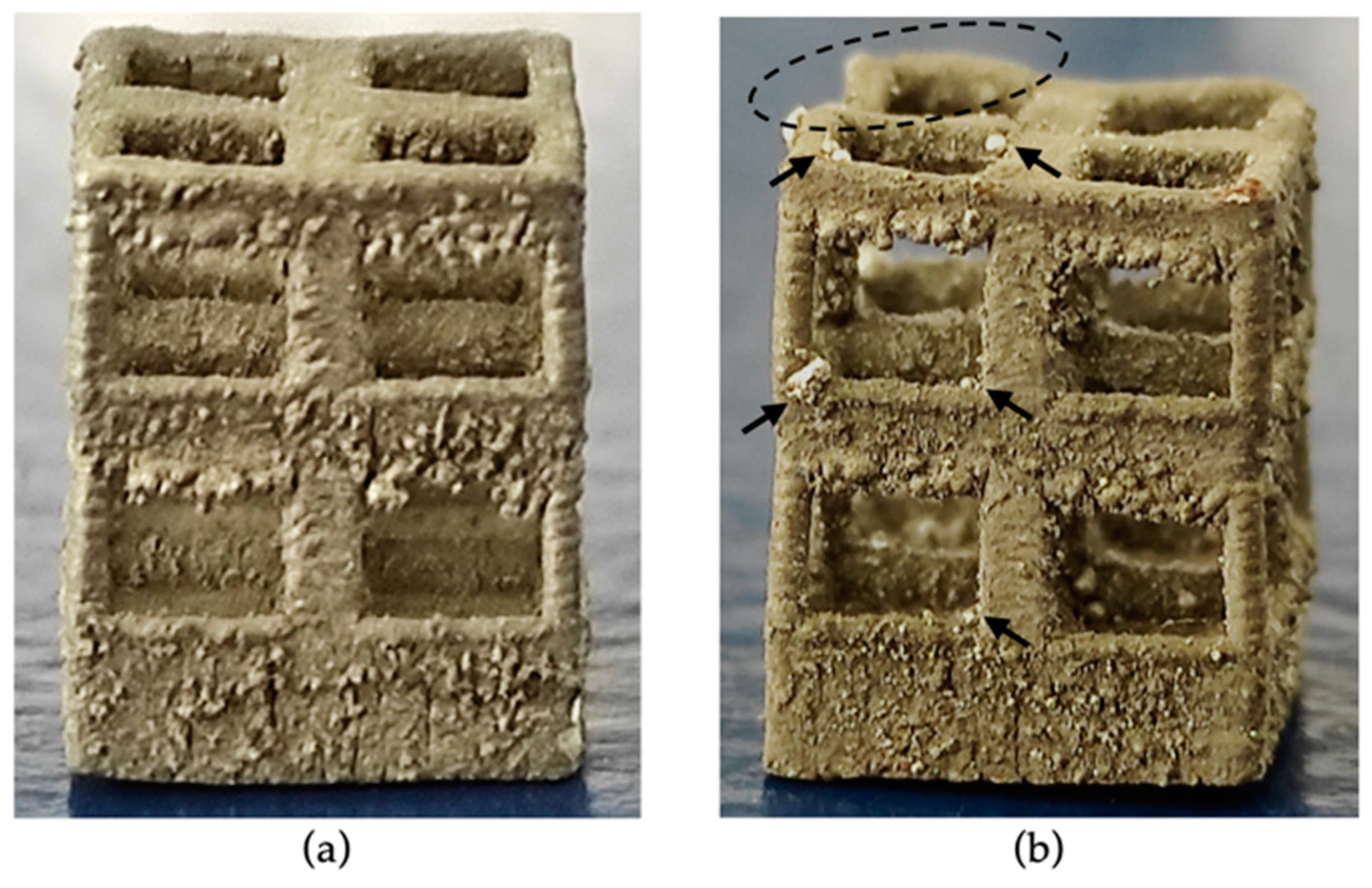
Lattice structures were produced using parameters I, i.e., hatch distance and point distance of 100 µm, correspondingly to those of sample I2. In as-built conditions (Figure 11a), the obtained structure does not show evident deformations or discrepancies with the CAD model. Poor surface quality is observed in the down-skin of horizontal trusses. After 100 thermal cycles between 180 °C and 280 °C, only a minimal deformation is observed in one of the upper corners (dashed ellipse in Figure 11b). Furthermore, Sn droplets (pointed out with arrows in Figure 11b) appear seldomly on surfaces.
SEM micrographs of the as-built lattice surface (Figure 12a) show the absence of surface cracks in vertical trusses, which are 0.5 mm or 1 mm wide. On the other hand, vertical cracks appear on horizontal trusses, which are 7 mm long. The distance between cracks ranges from 250 µm to 700 µm, with an average value of ~400 µm. The lowest average distances between longitudinal cracks can be found in the most highly constrained regions, i.e., at lattice nodes where 1 mm thick trusses converge, and at the bottom part of the lattice, in direct contact with the bulk Al substrate. After thermal cycling, lattice surface shows relatively coarse Sn droplets with diameter of hundreds of microns (Figure 12b), as well as small droplets with diameter below 50 µm and thread-like Sn whiskers (Figure 12c).
4. Discussion
4.1. Effect of Process Parameters on Microstructure
Various process parameters affected microstructural features, as phase distribution, discontinuities (pores and cracks) and topology of the upper surface. The main physical principle that lies behind them is that the energy input (here considered in terms of VED) during LPBF affects the local thermal history of the material. The laser scanning induces fast melting and solidification of the material and the formation of steep thermal gradients affecting also the already printed material, with a complex set of consequences on the microstructure of MGA. As observed in a previous work by Confalonieri and Gariboldi [16], Al-20%vol Sn alloy produced through LPBF has an extremely fine microstructure thanks to the high cooling rate of the molten pool. This small size of microstructural features is comparable with those observed for the same alloy produced through ball milling, compression and sintering [3,8,9]. In addition, a similar microstructure was obtained with LPBF by Zafari and Xia [19] for MGA Fe-20%vol Cu. During cooling, due to the immiscibility of the two phases, Al grains solidify first, while Sn is segregated at grain boundaries reducing primary grain growth [19]. If, due to high energy input, the cooling rate is relatively slow and extensive remelting occurs during deposition of upper layers, Al cells are relatively coarse and the structure appears generally homogeneous, see samples A and E in Figure 8. As VED decreases, the microstructure becomes finer with Al cells elongated in vertical cooling direction with Sn at boundaries; at the same, Sn agglomerates form especially at the bottom of the melting pool, “trapped” during the fast solidification, as previously discussed by the authors in [16]. Thus, low VED results in less homogeneous microstructure. With this phase distribution, which was not significantly modified by the upper layer deposition, the former molten pools can be more easily appreciated. These various types of microstructures can affect thermal diffusivity of the system, leading to an isotropic or anisotropic behavior accordingly [16].
Porosity changes significantly in each sample in terms of quantity, size, and location. The investigated values of hatch distance and point distance do not have a clear effect on porosity, which, in any case, seems to be more affected by the overall VED. To further analyze the correlation between process parameters and porosity, an alternative description of energy density values suggested by Ferro et al. [29] was applied (Equation (2)).
This expression includes thermal transport phenomena (α = powder thermal diffusivity, β = absorption coefficient, ϕ = spot size diameter). It relates the VED to the inverse of the product between hatch distance and the square root of point distance, while in Equation (1) the inverse proportionality of VED is with the product between hatch distance and the point distance. Accordingly, considering that C parameter is the same for all the samples, porosity and standard deviation of equivalent diameter are plot as function of (dh × dp0.5)−1 in Figure 13. Despite the change in VED dependency on hatch and point distance, the plots show the same trends observed in Figure 5 and Figure 6b, i.e., the point series does not follow a clear law. The complexity in relating process parameters to microstructural features can be ascribed to the peculiar features that characterize an MGA. In more detail, it should be considered that heat transfer phenomena, especially at low temperature, are significantly affected by the phase transition of low-melting phase and thermal properties cannot be considered constant with temperature, thus heat transport cannot be easily modelled.
In the investigated MGAs the formation of pores can be ascribed to two main causes: presence of gases in the molten pool and Sn particles detachment during specimen preparation (artifact). The presence of gas in the molten pool, which gives rise to spherical-shape pores, can be related to several causes [30]. First, shielding gas (Ar in the present case) can be trapped in the molten pool due to turbulence, which is more likely to occur at high VED. At the same time, turbulence in the molten pool is known to concurrently lead to the formation of peaks on upper surface of specimens [30]. In addition, moisture initially adsorbed by the powders can also be responsible for porosity [31]. Comparing samples I1 and I2, produced with the same parameters in the two batches, it is possible to observe that the one produced with dried powders (I2) smaller average pore size has a slightly lower amount of porosity (almost 1% less). The last gas-related cause for porosity is the evaporation of Sn due to the higher absorptivity of Sn with respect to Al and the high energies involved to melt Al, since it is necessary to break the Al oxide layer and to compensate the high laser reflectivity [32,33]. Despite the specific cause for pore formation, pore size tends to reduce with VED, since gas expansion is lower as temperature decreases and turbulence of molten pool is lower as well.
Gas pores tend to form closer to the external regions of the sample and to be bigger as VED increases. In facts, the outer regions of the samples are the hottest, because (i) they are affected by slower cooling rates, due to the fact that the surrounding unmolten powder has lower thermal diffusivity than the compacted material, and (ii) the laser direction is inverted following the meander scanning strategy, resulting in close consecutive laser pulses. This phenomenon is clearly more emphasized as VED increases together with more turbulence in the molten pool. On the other hand, lower VED values result in lower temperatures and, consequently, lower porosity, that is spread more homogeneously throughout the analyzed sections.
Vertical cracks are mainly caused by thermal stresses related to solidification shrinkage [18]. Sn has a solidification temperature much lower than Al, which means that solid and liquid coexist in a wide temperature range, thus promoting hot cracking. High VED, causing slower cooling rates and less severe thermal gradients, reduces cracks, especially in the inner part of samples that is more constrained. Moreover, as previously mentioned, the outer areas of high-VED specimens are hotter than the core, so cracks tend to concentrate in the middle of the sample, whereas cracks are distributed throughout the section in low-VED samples.
Hardness of the alloy can be considered as constant for samples produced in the same job. The difference between the hardness of samples of the two batches (+25% in batch 2 samples), can be reasonably ascribed to the effect of moisture. Dried powder (batch 2) shows less and smaller pores and higher hardness. Within samples of the same batch, considering that coarse discontinuities (e.g., cracks and big pores) were avoided during HV measurements, microstructural differences are probably too small to affect significantly hardness. Comparing the obtained values with earlier studies, hardness values obtained for the first batch (~30 HV) are close to values for cast and press-and-sintered Al-Sn alloys with the same nominal composition [1,34]. Hardness of samples from the second batch (~40 HV) are close to those of samples produced by ball-milled powder that are pressed-and-sintered [3,9].
Summarizing, according to microstructural analysis, the effects of process parameters are the following:
- Excessively high energy density increases pore size and results in accumulation of materials on the top surface corners;
- Most of the parameter sets lead to coarse porosity located at the outer surface, especially in high VED conditions. As energy decreases porosity is more homogeneously distributed in the sample;
- High energy results in coarse and homogeneous phase distribution;
- Low VED samples are more affected by hot-cracking.
Therefore, the best conditions, i.e., minimum number of pores and cracks are in the middle-right of the parameter matrix (see Table 1), are for parameter sets E, C, F, and I, since these process parameter sets have intermediate VED, balancing the effects of high and low VED.
4.2. Lattice Structures
Lattice structures were obtained by LPBF and proved to keep their shape almost unchanged after 100 thermal cycles across the solid/liquid transition of the Sn phase. Cracks were observed on as-built lattice surfaces only on horizontal trusses and not on vertical ones. Vertical beams are thin enough to avoid detrimentally high thermal stresses and, so, to prevent vertical crack formation. On the other hand, horizontal segments, show cracks with spacing comparable with that of bulk sample produced with the same process parameter combination (I2). This means that the designer can act both on process parameters and part geometry to reduce or avoid hot cracks.
After thermal cycling, Sn leaked out from the lattice surface. As previously seen for ball-milled and compressed samples [8,9], a fine microstructure without coarse interconnected particles, can help to reduce the risk of significant Sn losses. Nevertheless, the significance of this phenomenon depends on the service condition of the material. Indeed, a feature of interest can be the number of times the transition is activated in component life, i.e., only once (e.g., for safety device) or cyclically, leading to the functional fatigue of the material. Another feature to be considered is the environment where the Al-Sn component works, since Sn leakage could or could not damage other structures in the system.
5. Conclusions
The present work analyzed the effect of LPBF process parameters on Al-20%vol Sn alloy properties. Process parameters affect phase distribution, presence of discontinuities, and geometrical features of samples, while they did not change hardness significantly. To optimize each of these features, an intermediate VED with low hatch distance appears to give the best results, reducing the risk of pore and crack formation.
Furthermore, a lattice structure was successfully produced and proved to be relatively stable even after thermal cycling across Sn melting temperature. Such kind of metal PCM structure could potentially replace homogeneous Al-alloy lattice, providing a “safety function” to the part if temperature increases excessively. It could be inserted for instance in a more complex thermal storage device where a low melting organic PCM (e.g., a paraffin or a fatty acid) fills the Al-Sn alloy lattice, providing also mechanical strength and thermal conductivity.
Considerations on LPBF of Al-Sn alloy and thermal cycling of lattice structures could be extended to other miscibility gap alloys.
Author Contributions
Conceptualization, E.G.; data curation, C.C.; formal analysis, C.C.; investigation, C.C. and R.C.; resources, E.G.; visualization, C.C.; writing—original draft, C.C.; writing—review & editing, C.C., R.C., and E.G. All authors have read and agreed to the published version of the manuscript.
Funding
This research received no external funding.
Institutional Review Board Statement
Not applicable.
Informed Consent Statement
Not applicable.
Data Availability Statement
The raw data required to reproduce these findings cannot be shared at this time as the data also form part of an ongoing study. The processed data required to reproduce these findings cannot be shared at this time as the data also form part of an ongoing study.
Acknowledgments
The Italian Ministry of Education, University and Research is acknowledged for the support through the Project “Department of Excellence LIS4.0−Lightweight and Smart Structures for Industry 4.0.
Conflicts of Interest
The authors declare no conflict of interest.
References
- Liu, X.; Zeng, M.; Ma, Y.; Zhu, M. Promoting the high load-carrying capability of Al–20wt%Sn bearing alloys through creating nanocomposite structure by mechanical alloying. Wear 2012, 294–295, 387–394. [Google Scholar] [CrossRef]
- Sugo, H.; Kisi, E.; Cuskelly, D. Miscibility gap alloys with inverse microstructures and high thermal conductivity for high energy density thermal storage applications. Appl. Therm. Eng. 2013, 51, 1345–1350. [Google Scholar] [CrossRef]
- Confalonieri, C.; Perrin, M.; Gariboldi, E. Combined powder metallurgy routes to improve thermal and mechanical response of Al−Sn composite phase change materials. Trans. Nonferrous Met. Soc. China 2020, 30, 3226–3239. [Google Scholar] [CrossRef]
- Zhai, W.; Hu, L.; Geng, D.; Wei, B. Thermodynamic properties and microstructure evolution of ternary Al–10%Cu–x%Sn immiscible alloys. J. Alloys Compd. 2015, 627, 402–409. [Google Scholar] [CrossRef]
- Liu, X.; Zeng, M.; Ma, Y.; Zhu, M. Wear behavior of Al–Sn alloys with different distribution of Sn dispersoids manipulated by mechanical alloying and sintering. Wear 2008, 265, 1857–1863. [Google Scholar] [CrossRef]
- Lu, Z.; Zeng, M.; Gao, Y.; Zhu, M. Significant improvement of wear properties by creating micro/nano dual-scale structure in Al–Sn alloys. Wear 2012, 296, 469–478. [Google Scholar] [CrossRef]
- Liu, X.; Zeng, M.; Ma, Y.; Zhu, M. Melting behavior and the correlation of Sn distribution on hardness in a nanostructured Al–Sn alloy. Mater. Sci. Eng. A 2009, 506, 1–7. [Google Scholar] [CrossRef]
- Confalonieri, C.; Grimaldi, A.T.; Gariboldi, E. Ball-milled Al–Sn alloy as composite Phase Change Material. Mater. Today Energy 2020, 17, 100456. [Google Scholar] [CrossRef]
- Confalonieri, C.; Bassani, P.; Gariboldi, E. Microstructural and thermal response evolution of metallic form-stable phase change materials produced from ball-milled powders. J. Therm. Anal. 2020, 142, 85–96. [Google Scholar] [CrossRef]
- Makhatha, M.E.; Fatoba, O.S.; Akinlabi, E.T. Effects of rapid solidification on the microstructure and surface analyses of laser-deposited Al-Sn coatings on AISI 1015 steel. Int. J. Adv. Manuf. Technol. 2018, 94, 773–787. [Google Scholar] [CrossRef]
- Marrocco, T.; Driver, L.C.; Harris, S.J.; McCartney, D.G.; Mc Cartney, G. Microstructure and Properties of Thermally Sprayed Al-Sn-Based Alloys for Plain Bearing Applications. J. Therm. Spray Technol. 2006, 15, 634–639. [Google Scholar] [CrossRef]
- Lucchetta, M.C.; Saporiti, F.; Audebert, F. Improvement of surface properties of an Al–Sn–Cu plain bearing alloy produced by rapid solidification. J. Alloys Compd. 2019, 805, 709–717. [Google Scholar] [CrossRef]
- Kim, W.T.; Cantor, B. Solidification of tin droplets embedded in an aluminium matrix. J. Mater. Sci. 1991, 26, 2868–2878. [Google Scholar] [CrossRef]
- Zhang, W.; Zhao, B.; Zhai, Q.; Gao, Y. Application of Fast Scanning Calorimetry in the Rapid Solidification of Tin Particles Embedded in Al Matrix. In TMS2013 Supplemental Proceedings; Wiley: Hoboken, NJ, USA, 2013; pp. 477–484. [Google Scholar]
- Zhang, Z.; Wang, Y.; Bian, X.; Wang, W. Orientation of nanocrystals in rapidly solidified Al-based alloys and its correlation to the compound-forming tendency of alloys. J. Cryst. Growth 2005, 281, 646–653. [Google Scholar] [CrossRef]
- Confalonieri, C.; Gariboldi, E. Al-Sn Miscibility Gap Alloy produced by Power Bed Laser Melting for application as Phase Change Material. J. Alloys Compd. 2021, 881, 160596. [Google Scholar] [CrossRef]
- DebRoy, T.; Wei, H.; Zuback, J.; Mukherjee, T.; Elmer, J.; Milewski, J.; Beese, A.; Wilson-Heid, A.; De, A.; Zhang, W. Additive manufacturing of metallic components – Process, structure and properties. Prog. Mater. Sci. 2018, 92, 112–224. [Google Scholar] [CrossRef]
- Kim, W.R.; Bang, G.B.; Park, J.H.; Lee, T.W.; Lee, B.-S.; Yang, S.-M.; Kim, G.-H.; Lee, K.; Kim, H.G. Microstructural study on a Fe-10Cu alloy fabricated by selective laser melting for defect-free process optimization based on the energy density. J. Mater. Res. Technol. 2020, 9, 12834–12839. [Google Scholar] [CrossRef]
- Zafari, A.; Xia, K. Nano/ultrafine grained immiscible Fe-Cu alloy with ultrahigh strength produced by selective laser melting. Mater. Res. Lett. 2021, 9, 247–254. [Google Scholar] [CrossRef]
- Hubert, R.; Matar, O.B.; Foncin, J.; Coquet, P.; Tan, D.; Li, H.; Teo, E.H.T.; Merlet, T.; Pernod, P. An effective thermal conductivity model for architected phase change material enhancer: Theoretical and experimental investigations. Int. J. Heat Mass Transf. 2021, 176, 121364. [Google Scholar] [CrossRef]
- Li, Z.; Gariboldi, E. On the use of effective thermophysical properties to predict the melting process of composite phase change materials with coarse structures. Int. J. Heat Mass Transf. 2021, 180, 121765. [Google Scholar] [CrossRef]
- Vakhshouri, A.R. Paraffin as Phase Change Material. In Paraffin—An Overview; IntechOpen: London, UK, 2020. [Google Scholar]
- Li, Z.; Gariboldi, E. Modelling the conditions for natural convection onset in open-cell porous Al/paraffin composite phase change materials: Effects of temperature, paraffin type and metallic structure geometry. Int. J. Heat Mass Transf. 2021, 173, 121279. [Google Scholar] [CrossRef]
- Casati, R.; Vedani, M. Aging Response of an A357 Al Alloy Processed by Selective Laser Melting. Adv. Eng. Mater. 2019, 21, 1800406. [Google Scholar] [CrossRef]
- Rasband, W.S. ImageJ. 2018. Available online: https://imagej.net/Welcome (accessed on 20 March 2022).
- Ferreira, T.; Rasband, W. ImageJ User Guide. 2012. Available online: https://imagej.nih.gov/ij/docs/guide/146.html (accessed on 25 November 2019).
- Takashimizu, Y.; Iiyoshi, M. New parameter of roundness R: Circularity corrected by aspect ratio. Prog. Earth Planet. Sci. 2016, 3, 2. [Google Scholar] [CrossRef] [Green Version]
- Russ, J.C. The Image Processing Handbook; CRC Press: Boca Raton, FL, USA, 2006. [Google Scholar]
- Ferro, P.; Meneghello, R.; Savio, G.; Berto, F. A modified volumetric energy density–based approach for porosity assessment in additive manufacturing process design. Int. J. Adv. Manuf. Technol. 2020, 110, 1–11. [Google Scholar] [CrossRef]
- Zhang, J.; Song, B.; Wei, Q.; Bourell, D.; Shi, Y. A review of selective laser melting of aluminum alloys: Processing, microstructure, property and developing trends. J. Mater. Sci. Technol. 2019, 35, 270–284. [Google Scholar] [CrossRef]
- Weingarten, C.; Buchbinder, D.; Pirch, N.; Meiners, W.; Wissenbach, K.; Poprawe, R. Formation and reduction of hydrogen porosity during selective laser melting of AlSi10Mg. J. Mater. Process. Technol. 2015, 221, 112–120. [Google Scholar] [CrossRef]
- Wang, Z.; Ummethala, R.; Singh, N.; Tang, S.; Suryanarayana, C.; Eckert, J.; Prashanth, K.G. Selective Laser Melting of Aluminum and Its Alloys. Materials 2020, 13, 4564. [Google Scholar] [CrossRef]
- Yap, C.Y.; Chua, C.K.; Dong, Z.L. Preliminary investigation on selective laser melting of pure tin. Proc. Int. Conf. Prog. Addit. Manuf. 2016, 1290, 409–414. [Google Scholar]
- Gariboldi, E.; Perrin, M. Metallic Composites as Form-Stable Phase Change Alloys. Mater. Sci. Forum 2018, 941, 1966–1971. [Google Scholar] [CrossRef]
Figure 1.
SEM micrographs of Al (a) and Sn (b) powders.

Figure 2.
Three-dimensional model of lattice structure.
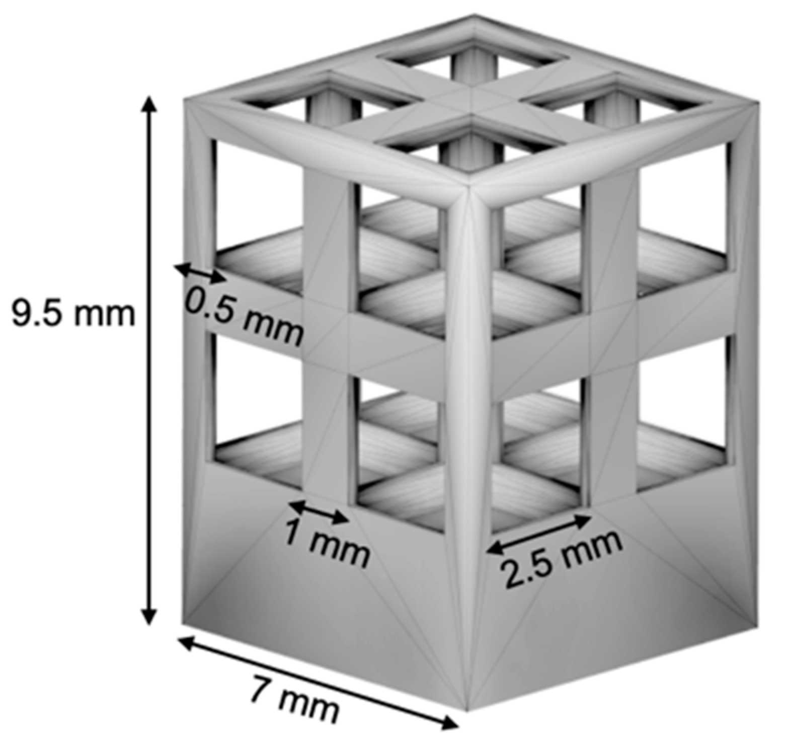
Figure 3.
Photographs of parallelepiped samples before removal from support; arrows indicate accumulated material at corners of upper surface in sample A.
Figure 3.
Photographs of parallelepiped samples before removal from support; arrows indicate accumulated material at corners of upper surface in sample A.

Figure 4.
Optical micrographs, process parameters (hatch distance and point distance) and features of samples (porosity, circularity, solidity, equivalent diameter ∅eq, and crack density dcracks). Shown sections are parallel to building direction (vertical).
Figure 4.
Optical micrographs, process parameters (hatch distance and point distance) and features of samples (porosity, circularity, solidity, equivalent diameter ∅eq, and crack density dcracks). Shown sections are parallel to building direction (vertical).
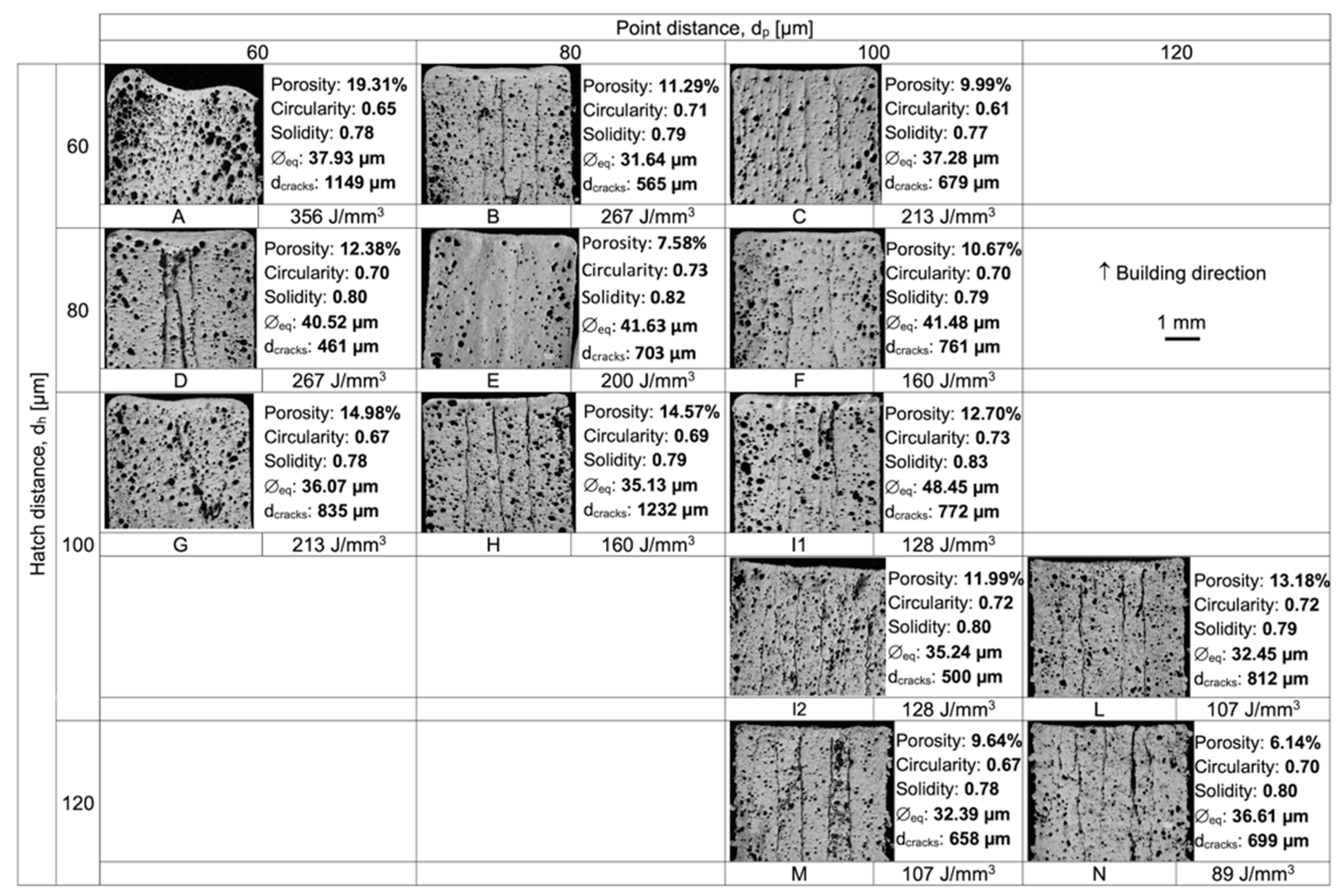
Figure 5.
Porosity for each sample as function of VED.

Figure 6.
Pore size distribution described through: (a) percentage of pores per equivalent diameter (each point corresponds to an equivalent diameter range ± 5 µm), and (b) standard deviation of equivalent diameter as function of VED.
Figure 6.
Pore size distribution described through: (a) percentage of pores per equivalent diameter (each point corresponds to an equivalent diameter range ± 5 µm), and (b) standard deviation of equivalent diameter as function of VED.
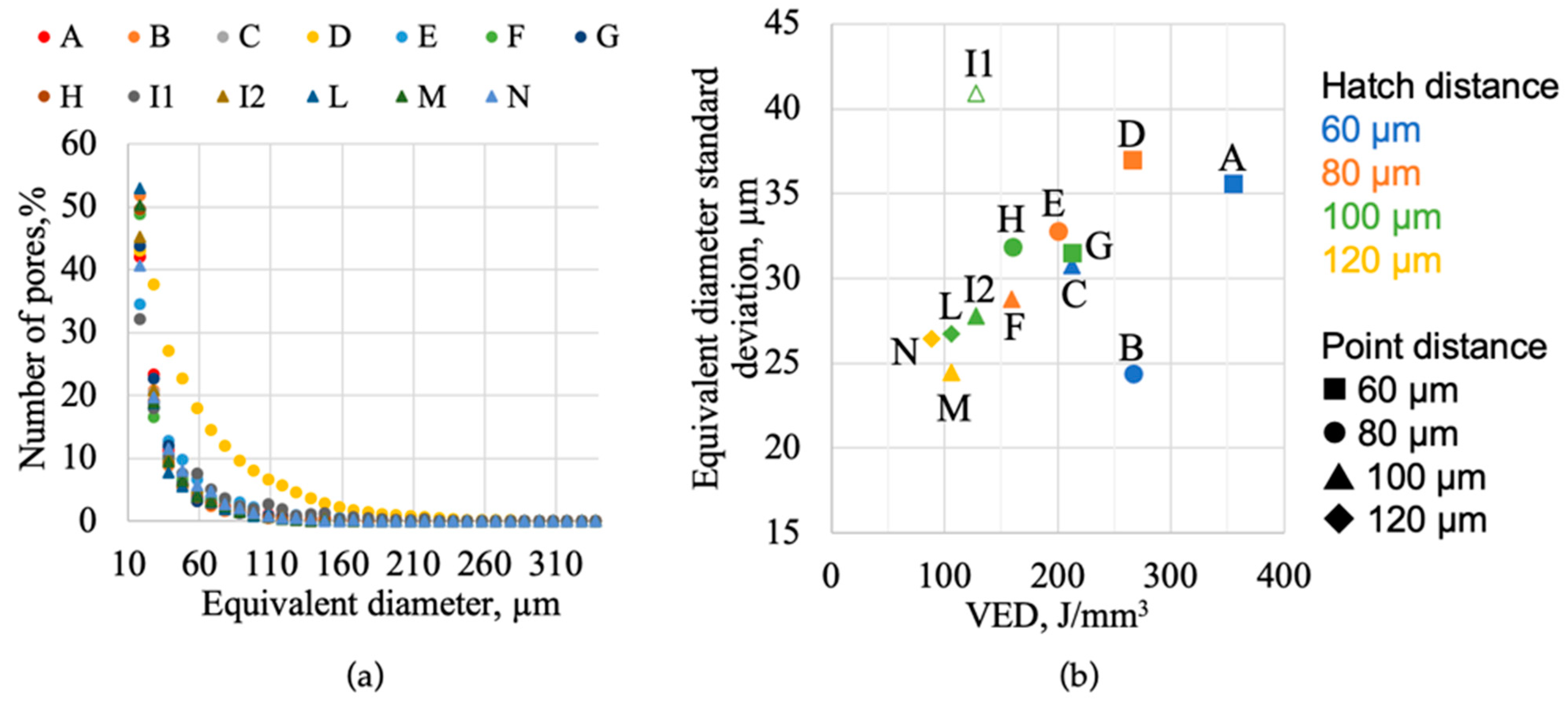
Figure 7.
OM micrograph of samples A, E, I1, and N: section perpendicular to the building direction.
Figure 7.
OM micrograph of samples A, E, I1, and N: section perpendicular to the building direction.
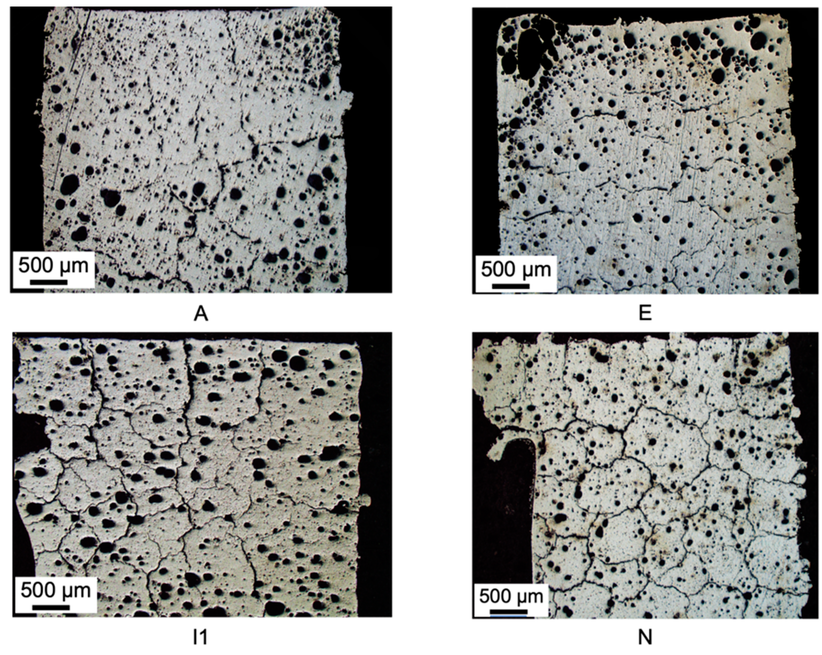
Figure 8.
SEM micrographs (BSE) of samples A, E, I2, and N at 3000× magnification.

Figure 9.
SEM micrographs (BSE) of sample I (a) and sample E (b) showing cracks at different orders of magnitude.
Figure 9.
SEM micrographs (BSE) of sample I (a) and sample E (b) showing cracks at different orders of magnitude.

Figure 10.
Vickers microhardness numbers for samples on the diagonal of parameter matrix (i.e., those with same hatch distance and point distance). Orange series and blue series indicate samples belonging to the first batch and to the second batch, respectively.
Figure 10.
Vickers microhardness numbers for samples on the diagonal of parameter matrix (i.e., those with same hatch distance and point distance). Orange series and blue series indicate samples belonging to the first batch and to the second batch, respectively.
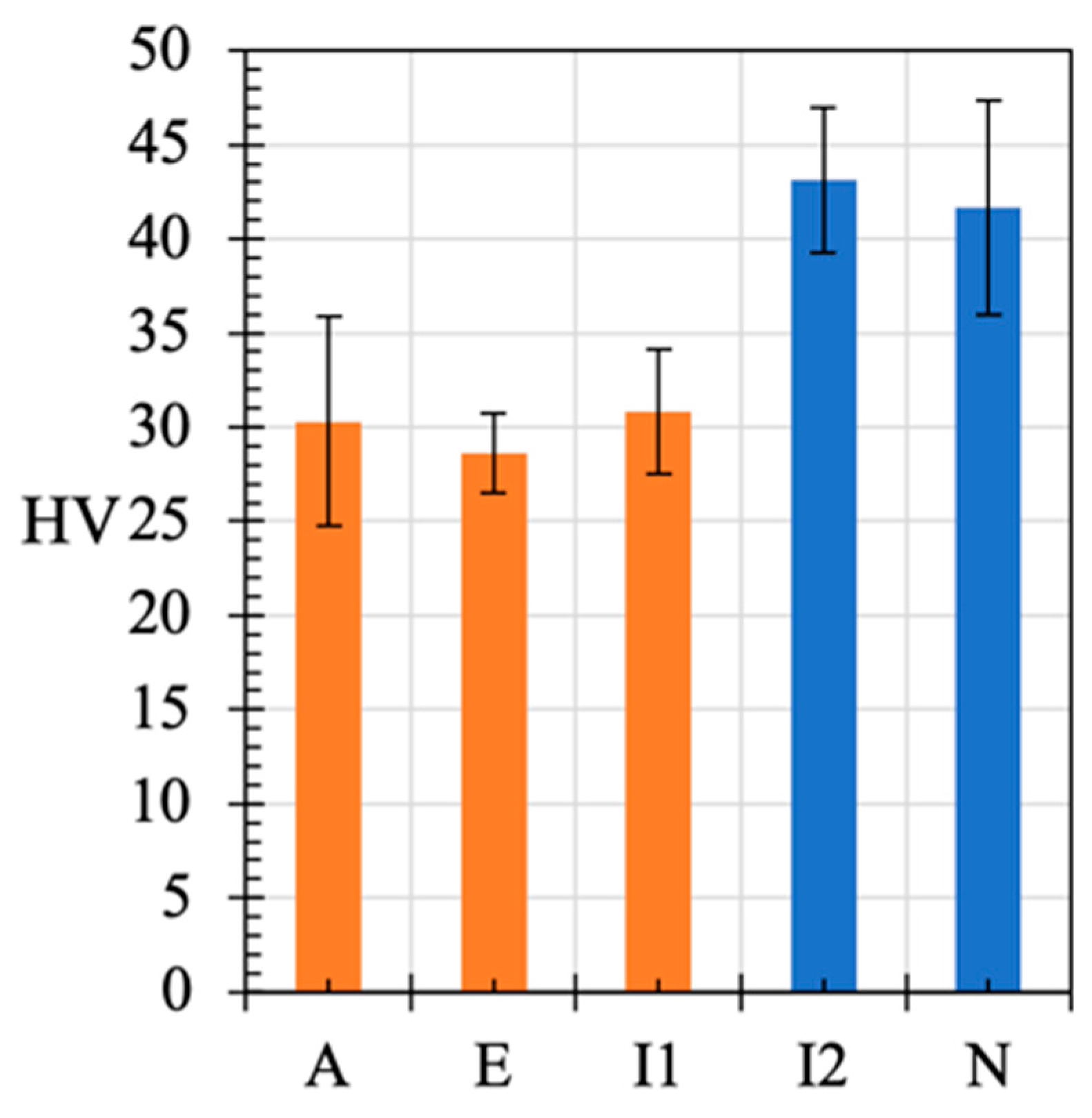
Figure 11.
Photographs of lattice structures in as-produced conditions (a) and after 100 cycles across Sn melting temperature (b). In image (b), the dashed ellipse highlights a deformed region of the lattice, and the arrows point out Sn droplets.
Figure 11.
Photographs of lattice structures in as-produced conditions (a) and after 100 cycles across Sn melting temperature (b). In image (b), the dashed ellipse highlights a deformed region of the lattice, and the arrows point out Sn droplets.

Figure 12.
SEM micrographs (SE) of lattice structure surface before (a) and after (b,c) thermal cycling. The schema shows micrographs position.
Figure 12.
SEM micrographs (SE) of lattice structure surface before (a) and after (b,c) thermal cycling. The schema shows micrographs position.

Figure 13.
Porosity for each sample (a) and standard deviation of equivalent diameter (b) as function of (dh × dp0.5)−1, representing the alternative description of VED according to [29].
Figure 13.
Porosity for each sample (a) and standard deviation of equivalent diameter (b) as function of (dh × dp0.5)−1, representing the alternative description of VED according to [29].

Table 1.
Sample names and VED calculated accordingly to Equation (1).
| Point Distance, dp [µm] | |||||
|---|---|---|---|---|---|
| 60 | 80 | 100 | 120 | ||
| Hatch distance, dh [µm] | 60 | A 356 J/mm3 | B 267 J/mm3 | C 213 J/mm3 | |
| 80 | D 267 J/mm3 | E 200 J/mm3 | F 160 J/mm3 | ||
| 100 | G 213 J/mm3 | H 160 J/mm3 | I 128 J/mm3 | L 107 J/mm3 | |
| 120 | M 107 J/mm3 | N 89 J/mm3 | |||
Publisher’s Note: MDPI stays neutral with regard to jurisdictional claims in published maps and institutional affiliations. |
© 2022 by the authors. Licensee MDPI, Basel, Switzerland. This article is an open access article distributed under the terms and conditions of the Creative Commons Attribution (CC BY) license (https://creativecommons.org/licenses/by/4.0/).
Share and Cite
MDPI and ACS Style
Confalonieri, C.; Casati, R.; Gariboldi, E. Effect of Process Parameters on Laser Powder Bed Fusion of Al-Sn Miscibility Gap Alloy. Quantum Beam Sci. 2022, 6, 17. https://doi.org/10.3390/qubs6020017
AMA Style
Confalonieri C, Casati R, Gariboldi E. Effect of Process Parameters on Laser Powder Bed Fusion of Al-Sn Miscibility Gap Alloy. Quantum Beam Science. 2022; 6(2):17. https://doi.org/10.3390/qubs6020017
Chicago/Turabian StyleConfalonieri, Chiara, Riccardo Casati, and Elisabetta Gariboldi. 2022. "Effect of Process Parameters on Laser Powder Bed Fusion of Al-Sn Miscibility Gap Alloy" Quantum Beam Science 6, no. 2: 17. https://doi.org/10.3390/qubs6020017