
A Survey of Process Monitoring Using Computer-Aided Inspection in Laser-Welded Blanks of Light Metals Based on the Digital Twins Concept

 ,
,  , ,
, ,  and
and 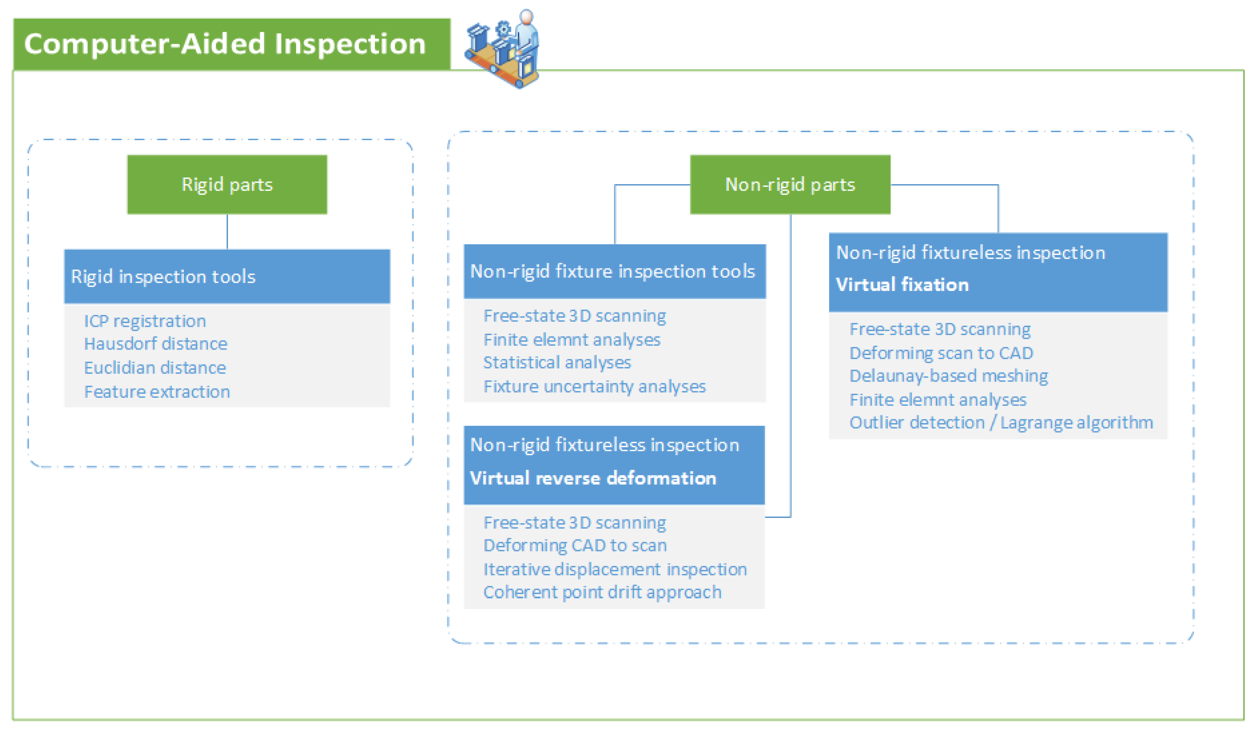
Abstract
:1. Introduction
2. Quality Control Based on 3D Geometrical Inspection
3. Verification and Validation of the Methods in CAI
4. Digital Twins (DT)
5. Summary and Future Scopes
Author Contributions
Funding
Institutional Review Board Statement
Informed Consent Statement
Data Availability Statement
Conflicts of Interest
References
- Katayama, S. Handbook of Laser Welding Technologies; Elsevier: Amsterdam, The Netherlands, 2013. [Google Scholar]
- Zhao, F.; Xu, X.; Xie, S.Q. Computer-Aided Inspection Planning-The state of the art. Comput. Ind. 2009, 60, 453–466. [Google Scholar] [CrossRef]
- Minetola, P.; Iuliano, L.; Calignano, F. A customer oriented methodology for reverse engineering software selection in the computer aided inspection scenario. Comput. Ind. 2015, 67, 54–71. [Google Scholar] [CrossRef]
- Zhang, L.; Chen, X.; Zhou, W.; Cheng, T.; Chen, L.; Guo, Z. Digital Twins for Additive Manufacturing: A State-of-the-Art Review. Appl. Sci. 2020, 10, 8350. [Google Scholar] [CrossRef]
- Gaha, R.; Durupt, A.; Eynard, B. Towards the implementation of the Digital Twin in CMM inspection process: Opportunities, challenges and proposals. Procedia Manuf. 2020, 54, 216–221. [Google Scholar] [CrossRef]
- Papacharalampopoulos, A.; Michail, C.; Stavropoulos, P. Manufacturing Process Control through a Digital Twin: Encoding Issues. In Proceedings of the TESConf 2020—9th International Conference Through-Life Engineering Services, Cranfield, Bedfordshire, UK, 3–4 November 2020. [Google Scholar] [CrossRef]
- Kong, F.; Ma, J.; Carlson, B.; Kovacevic, R. Real-time monitoring of laser welding of galvanized high strength steel in lap joint configuration. Opt. Laser Technol. 2012, 44, 2186–2196. [Google Scholar] [CrossRef]
- Sebestova, H.; Chmelickova, H.; Nozka, L.; Moudry, J. Non-destructive real time monitoring of the laser welding process. J. Mater. Eng. Perform. 2012, 21, 764–769. [Google Scholar] [CrossRef]
- Liu, W.; Liu, S.; Ma, J.; Kovacevic, R. Real-time monitoring of the laser hot-wire welding process. Opt. Laser Technol. 2014, 57, 66–76. [Google Scholar] [CrossRef]
- Harooni, M.; Carlson, B.; Kovacevic, R. Detection of defects in laser welding of AZ31B magnesium alloy in zero-gap lap joint configuration by a real-time spectroscopic analysis. Opt. Lasers Eng. 2014, 56, 54–66. [Google Scholar] [CrossRef]
- Blecher, J.J.; Galbraith, C.M.; Van Vlack, C.; Palmer, T.A.; Fraser, J.M.; Webster, P.J.L.; DebRoy, T. Real time monitoring of laser beam welding keyhole depth by laser interferometry. Sci. Technol. Weld. Join. 2014, 19, 560–564. [Google Scholar] [CrossRef]
- Luo, Z.; Liu, W.; Wang, Z.; Ao, S. Monitoring of laser welding using source localization and tracking processing by microphone array. Int. J. Adv. Manuf. Technol. 2016, 86, 21–28. [Google Scholar] [CrossRef]
- Mirapeix, J.; Vila, E.; Valdiande, J.J.; Riquelme, A.; Garcia, M.; Cobo, A. Real-time detection of the aluminium contribution during laser welding of Usibor1500 tailor-welded blanks. J. Mater. Process. Technol. 2016, 235, 106–113. [Google Scholar] [CrossRef] [Green Version]
- Aminzadeh, A.; Karganroudi, S.S.; Barka, N.; El Ouafi, A. A real-time 3D scanning of aluminum 5052-H32 laser welded blanks; geometrical and welding characterization. Mater. Lett. 2021, 296, 129883. [Google Scholar] [CrossRef]
- Aminzadeh, A.; Karganroudi, S.S.; Barka, N. A novel approach of residual stress prediction in ST-14/ST-44 laser welded blanks; mechanical characterization and experimental validation. Mater. Lett. 2021, 285, 129193. [Google Scholar] [CrossRef]
- Aminzadeh, A.; Nasiri, N.; Barka, N.; Parvizi, A.; Abrinia, K.; Moradi, M.; Sattarpanah Karganroudi, S. Statistical Analysis of Laser-Welded Blanks in Deep Drawing Process: Response Surface Modeling. J. Mater. Eng. Perform. 2022, 31, 2240–2256. [Google Scholar] [CrossRef]
- Aminzadeh, A.; Sattarpanah Karganroudi, S.; Barka, N. Experimental and numerical investigation of forming defects and stress analysis in laser-welded blanks during deep drawing process. Int. J. Adv. Manuf. Technol. 2021, 117, 1193–1207. [Google Scholar] [CrossRef]
- Aminzadeh, A.; Parvizi, A.; Moradi, M. Multi-objective topology optimization of deep drawing dissimilar tailor laser welded blanks; experimental and finite element investigation. Opt. Laser Technol. 2020, 125, 106029. [Google Scholar] [CrossRef]
- Aminzadeh, A.; Parvizi, A.; Safdarian, R.; Rahmatabadi, D. Comparison between laser beam and gas tungsten arc tailored welded blanks via deep drawing. Proc. Inst. Mech. Eng. Part B J. Eng. Manuf. 2020, 235, 673–688. [Google Scholar] [CrossRef]
- Wang, T.; Chen, J.; Gao, X.; Qin, Y. Real-time monitoring for disk laser welding based on feature selection and SVM. Appl. Sci. 2017, 7, 884. [Google Scholar] [CrossRef] [Green Version]
- Wang, T.; Chen, J.; Gao, X.; Li, W. Quality monitoring for laser welding based on high-speed photography and support vector machine. Appl. Sci. 2017, 7, 299. [Google Scholar] [CrossRef] [Green Version]
- De Bono, P.; Allen, C.; D’Angelo, G.; Cisi, A. Investigation of optical sensor approaches for real-time monitoring during fibre laser welding. J. Laser Appl. 2017, 29, 022417. [Google Scholar] [CrossRef] [Green Version]
- Chen, J.; Wang, T.; Gao, X.; Wei, L. Real-time monitoring of high-power disk laser welding based on support vector machine. Comput. Ind. 2018, 94, 75–81. [Google Scholar] [CrossRef]
- Pasinetti, S.; Sansoni, G.; Docchio, F. In-Line Monitoring of Laser Welding Using a Smart Vision System. In Proceedings of the IEEE Metrology for Industry 4.0 and IoT, Brescia, Italy, 16–18 April 2018; pp. 134–139. [Google Scholar] [CrossRef] [Green Version]
- Lei, Z.; Shen, J.; Wang, Q.; Chen, Y. Real-time weld geometry prediction based on multi-information using neural network optimized by PCA and GA during thin-plate laser welding. J. Manuf. Process. 2019, 43, 207–217. [Google Scholar] [CrossRef]
- Zhang, Y.; You, D.; Gao, X.; Katayama, S. Online Monitoring of Welding Status Based on a DBN Model During Laser Welding. Engineering 2019, 5, 671–678. [Google Scholar] [CrossRef]
- Haubold, M.W.; Zäh, M.F. Real-time spatter detection in laser welding with beam oscillation. Procedia CIRP 2019, 79, 159–164. [Google Scholar] [CrossRef]
- Shevchik, S.A.; Le-Quang, T.; Farahani, F.V.; Faivre, N.; Meylan, B.; Zanoli, S.; Wasmer, K. Laser welding quality monitoring via graph support vector machine with data adaptive kernel. IEEE Access 2019, 7, 93108–93122. [Google Scholar] [CrossRef]
- Zhang, Z.; Li, B.; Zhang, W.; Lu, R.; Wada, S.; Zhang, Y. Real-time penetration state monitoring using convolutional neural network for laser welding of tailor rolled blanks. J. Manuf. Syst. 2020, 54, 348–360. [Google Scholar] [CrossRef]
- Gonzalez-Val, C.; Pallas, A.; Panadeiro, V.; Rodriguez, A. A convolutional approach to quality monitoring for laser manufacturing. J. Intell. Manuf. 2020, 31, 789–795. [Google Scholar] [CrossRef] [Green Version]
- Keawprachum, B.; Srisungsitthisunti, P. Real-time process monitoring of laser welding by infrared camera and image processing. Key Eng. Mater. 2020, 856, 160–168. [Google Scholar] [CrossRef]
- Papacharalampopoulos, A.; Stavropoulos, P.; Petrides, D. Towards a digital twin for manufacturing processes: Applicability on on laser laser welding. Procedia CIRP 2019, 88, 110–115. [Google Scholar] [CrossRef]
- Sattarpanah Karganroudi, S. Contribution à L’inspection Automatique des Pièces Flexibles à L’état Libre Sans Gabarit de Conformation; Université du Québec à Trois-Rivières: Trois-Rivières, QC, Canada, 2017. [Google Scholar]
- Sabri, V.; Sattarpanah, S.; Tahan, S.A.; Cuillière, J.C.; François, V.; Pham, X.T. A robust and automated FE-based method for fixtureless dimensional metrology of non-rigid parts using an improved numerical inspection fixture. Int. J. Adv. Manuf. Technol. 2017, 92, 2411–2423. [Google Scholar] [CrossRef]
- Babanezhad, K.; Aidibe, A.; Foucault, G.; Tahan, A.; Bigeon, J. Improved Bi-Criterion flexible registration for fixtureless inspection of compliant parts. Precis. Eng. 2020, 65, 116–129. [Google Scholar] [CrossRef]
- Sattarpanah Karganroudi, S.; Cuillière, J.-C.; François, V.; Tahan, S.-A. “What-if” scenarios towards virtual assembly-state mounting for non-rigid parts inspection using permissible loads. Int. J. Adv. Manuf. Technol. 2018, 97, 353–373. [Google Scholar] [CrossRef]
- Besl, P.J.; McKay, N.D. Method for registration of 3-D shapes. In Sensor Fusion IV: Control Paradigms and Data Structures; SPIE: Bellingham, WA, USA, 1992; Volume 1611, pp. 586–606. [Google Scholar]
- Li, Y.; Gu, P. Free-form surface inspection techniques state of the art review. Comput. Des. 2004, 36, 1395–1417. [Google Scholar] [CrossRef]
- Savio, E.; Chiffre, L.D.; Schmittc, R. Metrology of freeform shaped parts. CIRP Ann. 2007, 56, 810–835. [Google Scholar] [CrossRef]
- Ravishankar, S.; Dutt, H.; Gurumoorthy, B. Automated inspection of aircraft parts using a modified ICP algorithm. Int. J. Adv. Manuf. Technol. 2010, 46, 227–236. [Google Scholar] [CrossRef]
- Henrikson, J. Completeness and total boundedness of the Hausdorff metric. MIT Undergrad. J. Math. 1999, 1, 10. [Google Scholar]
- Masuda, T.; Yokoya, N. A robust method for registration and segmentation of multiple range images. Comput. Vis. Image Underst. 1995, 61, 295–307. [Google Scholar] [CrossRef]
- Rusinkiewicz, S.; Levoy, M. Efficient variants of the ICP algorithm. In Proceedings of the Third International Conference on 3-D Digital Imaging and Modeling, Quebec City, QC, Canada, 28 May–1 June 2001; pp. 145–152. [Google Scholar]
- Greenspan, M.; Godin, G. A nearest neighbor method for efficient ICP. In Proceedings of the Third International Conference on 3-D Digital Imaging and Modeling, Quebec City, QC, Canada, 28 May–1 June 2001; pp. 161–168. [Google Scholar]
- Zhu, L.; Barhak, J.; Srivatsan, V.; Katz, R. Efficient registration for precision inspection of free-form surfaces. Int. J. Adv. Manuf. Technol. 2007, 32, 505–515. [Google Scholar] [CrossRef] [Green Version]
- Sattarpanah Karganroudi, S.; Cuillière, J.-C.; Francois, V.; Tahan, S.-A. Automatic fixtureless inspection of non-rigid parts based on filtering registration points. Int. J. Adv. Manuf. Technol. 2016, 87, 687–712. [Google Scholar] [CrossRef]
- Schwer, L.E. An overview of the PTC 60/V&V 10: Guide for verification and validation in computational solid mechanics. Eng. Comput. 2007, 23, 245–252. [Google Scholar]
- Roy, R.B.; Mishra, D.; Pal, S.K.; Chakravarty, T.; Panda, S.; Chandra, M.G.; Pal, A.; Misra, P.; Chakravarty, D.; Misra, S. Digital twin: Current scenario and a case study on a manufacturing process. Int. J. Adv. Manuf. Technol. 2020, 107, 3691–3714. [Google Scholar] [CrossRef]
- Zheng, Y.; Yang, S.; Cheng, H. An application framework of digital twin and its case study. J. Ambient. Intell. Humaniz. Comput. 2019, 10, 1141–1153. [Google Scholar] [CrossRef]
- Mohan, D.G.; Tomków, J.; Sattarpanah Karganroudi, S. Laser Welding of UNS S33207 Hyper-Duplex Stainless Steel to 6061 Aluminum Alloy Using High Entropy Alloy as a Filler Material. Appl. Sci. 2022, 12, 2849. [Google Scholar] [CrossRef]
- Duriagina, Z.; Holyaka, R.; Tepla, T.; Kulyk, V.; Arras, P.; Eyngorn, E. Identification of Fe3O4 nanoparticles biomedical purpose by magnetometric methods. In Biomaterials in Regenerative Medicine; InTech: Rijeka, Croatia, 2018; p. 448. [Google Scholar] [CrossRef] [Green Version]


Publisher’s Note: MDPI stays neutral with regard to jurisdictional claims in published maps and institutional affiliations. |
© 2022 by the authors. Licensee MDPI, Basel, Switzerland. This article is an open access article distributed under the terms and conditions of the Creative Commons Attribution (CC BY) license (https://creativecommons.org/licenses/by/4.0/).
Share and Cite
Aminzadeh, A.; Sattarpanah Karganroudi, S.; Meiabadi, M.S.; Mohan, D.G.; Ba, K. A Survey of Process Monitoring Using Computer-Aided Inspection in Laser-Welded Blanks of Light Metals Based on the Digital Twins Concept. Quantum Beam Sci. 2022, 6, 19. https://doi.org/10.3390/qubs6020019
Aminzadeh A, Sattarpanah Karganroudi S, Meiabadi MS, Mohan DG, Ba K. A Survey of Process Monitoring Using Computer-Aided Inspection in Laser-Welded Blanks of Light Metals Based on the Digital Twins Concept. Quantum Beam Science. 2022; 6(2):19. https://doi.org/10.3390/qubs6020019
Chicago/Turabian StyleAminzadeh, Ahmad, Sasan Sattarpanah Karganroudi, Mohammad Saleh Meiabadi, Dhanesh G. Mohan, and Kadiata Ba. 2022. "A Survey of Process Monitoring Using Computer-Aided Inspection in Laser-Welded Blanks of Light Metals Based on the Digital Twins Concept" Quantum Beam Science 6, no. 2: 19. https://doi.org/10.3390/qubs6020019