Railway Vehicle Wheel Restoration by Submerged Arc Welding and Its Characterization


1
Advanced Railroad Vehicle Division, Korea Railroad Research Institute, Uiwang-si 16105, Korea
2
Asia-Tech Co., Ltd., Jecheon-si 27159, Korea
*
Author to whom correspondence should be addressed.
Sci 2020, 2(2), 33; https://doi.org/10.3390/sci2020033
Submission received: 11 April 2019
/
Accepted: 12 April 2019
/
Published: 14 May 2020
Abstract
:When a railway vehicle moves on a curved rail, sliding contact occurs between the rail head side and wheel flange, which wears the wheel flange down. The thinned flange needs to be restored above the required minimum thickness for structural safety. In this study, a new process and welding wire for restoring worn-out railway wheels by submerged arc welding was developed. To characterize the properties of the restored wheel, dilatometric analysis of phase transformation, SEM/EDX analyses, hardness measurement, and residual stress measurement using the X-ray diffraction method were performed. Finally, wear tests with full-size wheel/rail specimens were carried out. It was confirmed that the weld metal was composed of bainitic microstructures as intended, and welding defects were not observed. The wear amount of the restored wheel was greater than that of the base material, but it was less than half of the wear depth of the weld-repaired wheel with ferritic–pearlitic microstructures. The developed process seems applicable to industry.
1. Introduction
Railway vehicles move on the rail using frictional force between the rail and the wheel. When a railway vehicle rolls in a straight line, the wheel-rail rolling contact mostly occurs between the wheel tread and rail head top surface. On a curved line, sliding contact also takes place between the wheel flange and rail head side, which wears and thins the wheel flange down. The flange plays an important role in supporting the lateral force transmitted by the centrifugal force of the vehicle. So a certain thickness is necessary for structural safety. When the flange thickness becomes thinner than the specified value, the wheel section profile is restored by machine work, which shaves off much of the rim of the wheel, so the wheel reaches the end of its lifetime after several times of reprofiling. It is estimated that more than a million railway wheels are discarded globally every year due to flange wear. It takes lots of time and money to dispose of worn-out wheels and to manufacture new wheels. Producing new wheels consumes a great deal of energy and emits a lot of carbon dioxide.
For the above reasons and sustainable development, overlay welding has been widely used in industry to extend the lifetime of the worn-out parts, and/or to protect the wear of machine parts such as valve seat ring [1], chisel ploughshare [2], excavator teeth [3,4], pipeline valve [5], crane wheel [6,7], turbine blade [8], railway wheels [9,10], etc. Plasma transfer arc welding, gas metal arc welding, laser beam welding, and submerged arc welding are used for overlay welding [11]. Malinov et al. [6] reconditioned worn crane wheels by welding and obtained weld metal containing austenite reinforced with carbide. The weld metal showed a self-quenching effect by martensitic transformation under service loading. Anan’ev et al. [7] investigated the effect of welding wire on the microstructures and wear resistance of hardfaced crane wheels. Concerning the repair welding of railway vehicle wheels, a lot of study on wheel flange hardfacing has been performed in Ukraine, and hardfaced wheels have been practically used. Gajvoronsky et al. [9] hardfaced a wheel with a composition of 0.625 wt.% C; 0.73 Mn; 0.31 Si; 0.11 V by submerged arc welding. They showed the influence of post weld cooling rate on the microstructures and mechanical properties. When the cooling rate was lowered from 33 °C/s to 11.1 °C/s, martensitic content in the heat affected zone decreased; the volume fraction of ferrite-pearlite component increased; and the bainite content was stabilized. Markisha et al. [10] studied the effect of welding wire composition on microstructure and mechanical properties. Using welding wire with C 0.12 wt.%, Mn 1.0, Si 0.35, Cr 0.67, Ni 0.8, V 0.1, Mo 0.4, a weld metal composed of bainitic and martensitic phases was obtained, and that composition gave the weld metal relatively higher yield strength and fracture toughness.
The two basic requirements of materials for railway wheels and rails are wear resistance and rolling contact fatigue resistance. In general, these properties are incompatible with each other. Conventionally ferritic–pearlitic alloys have been used for railway wheels and rails. Although they have many merits such as low cost, wear resistance, weldability and easy production, etc., it is difficult to further improve their mechanical strength and rolling contact fatigue resistance. One alternative is bainitic steel, which is known to have higher mechanical strength and fracture toughness than ferritic–pearlitic steels. Gianni et al. [12] presented a bainitic railway wheel for heavy haul application, and showed through field tests in a service line that it had a better rolling contact and thermal fatigue resistance than an AAR Class C wheel with ferritic–pearlitic structures.
In this study, the main focus is on the development of a hardfacing process and welding wire for worn wheel flanges using submerged arc welding which gives the weld metal a bainitic micro structure. Characterization of the mechanical properties, microstructural examination, and residual stress measurement, and wear tests, etc. were carried out.
2. Materials and Methods
2.1. Welding Wire and Dilatometric Analysis of Phase Transformation
Overlay-welded wheels have to satisfy basic properties (see EN 13262) such as hardness, mechanical strength, fracture toughness, elongation rate, wear resistance, etc. In addition, it is very important to prevent cracks that may occur during welding or after welding. To solve these problems, a welding wire must first be developed. Several candidate materials have been tried. After various tests for the candidate materials, one was chosen. The material was composed of C 0.06 wt.%, Mn 2.37, Si 1.38, Cr 0.90, Ni 0.53, Ti 0.026, V 0.06 (Table 1). φ2.0 welding wire was produced using the material. In Table 1, the composition of the wheel is from Korean Standard KS R 9221 [13]. The composition of the weld metal were measured in the weld metal fusion zone.
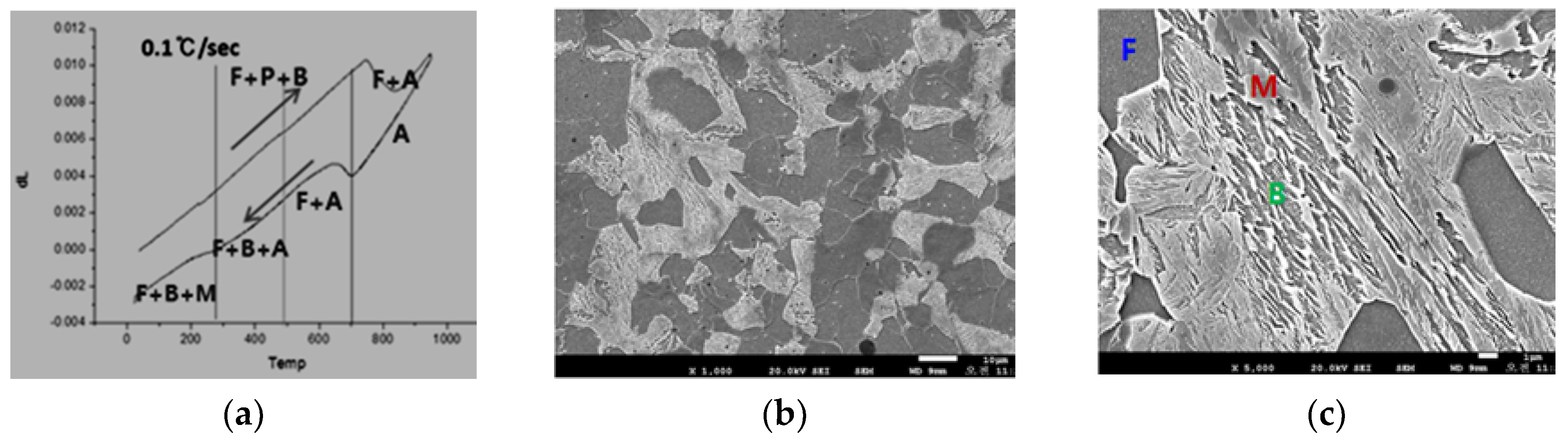
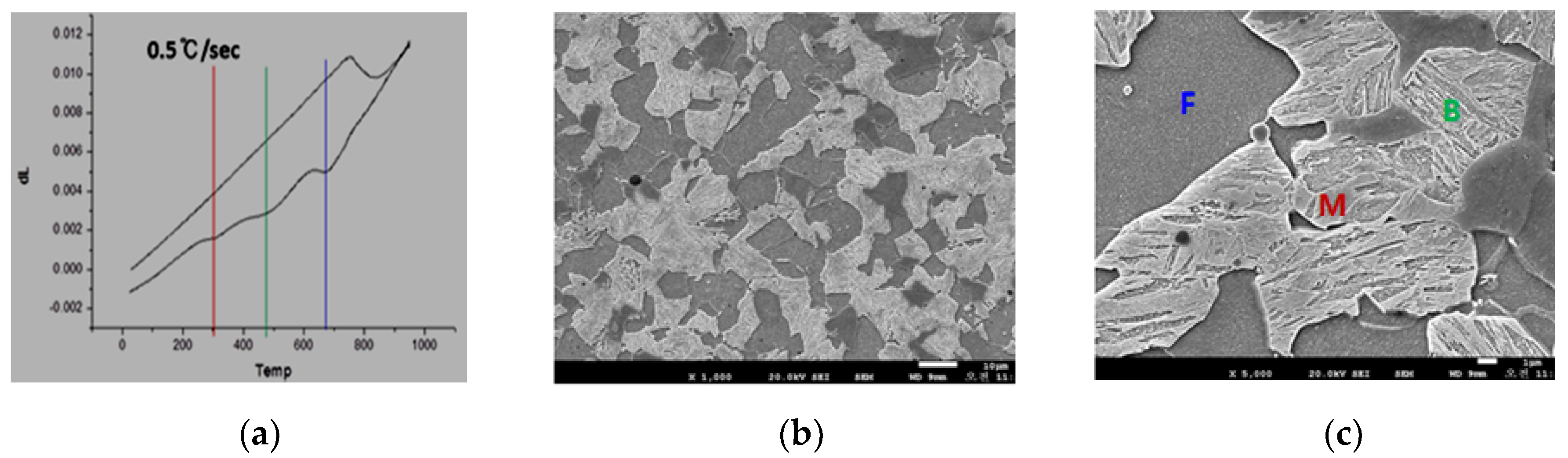
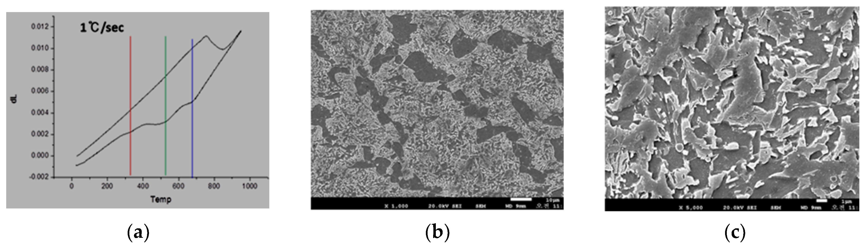
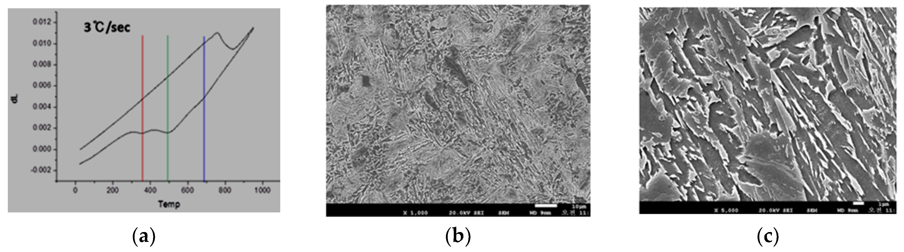
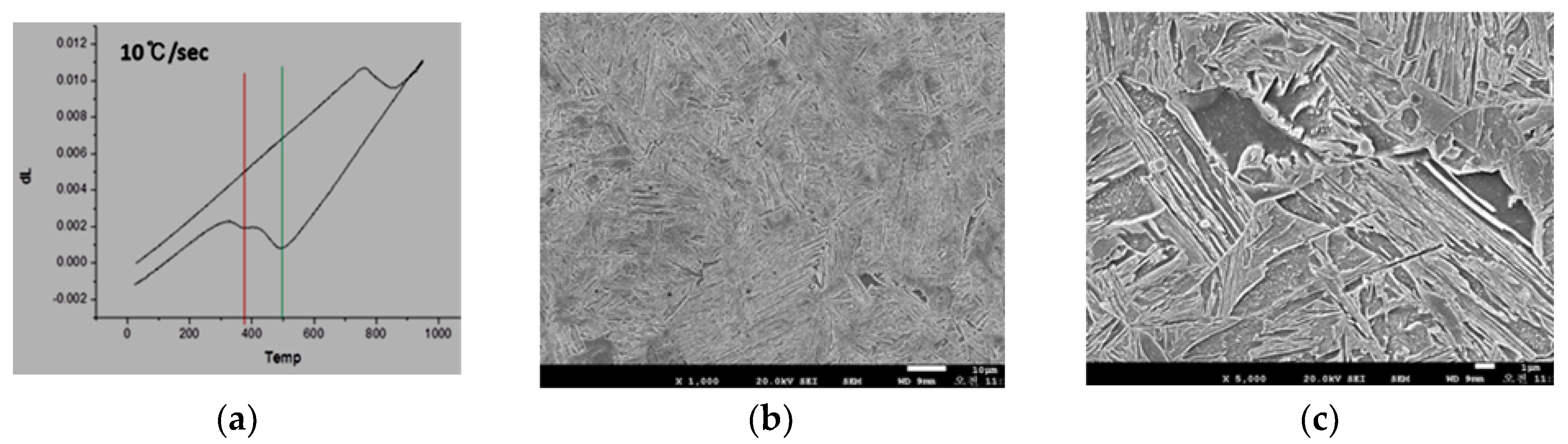
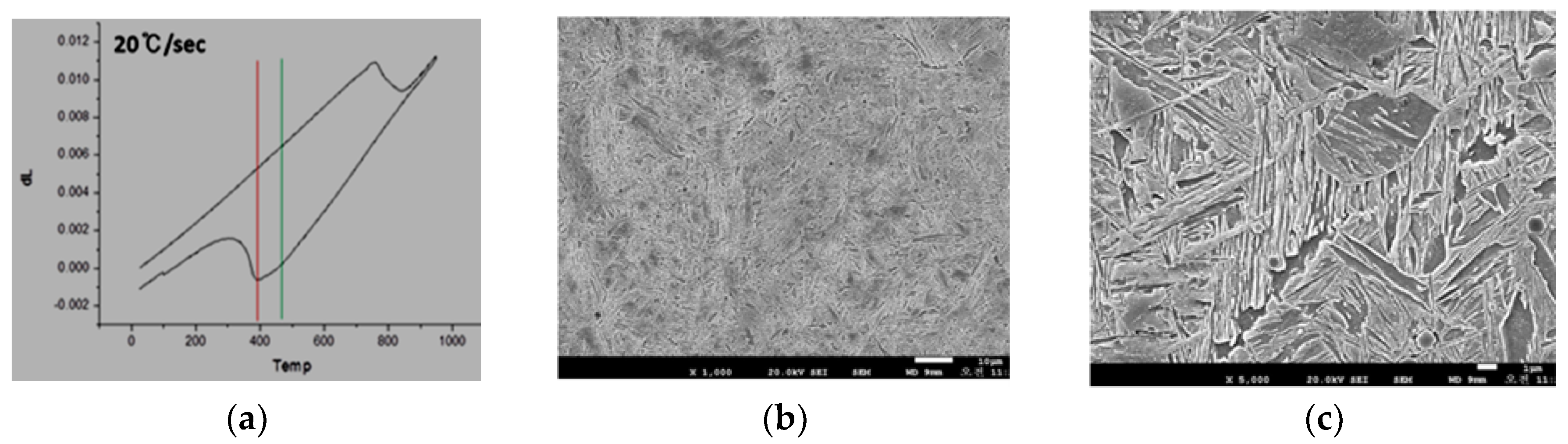
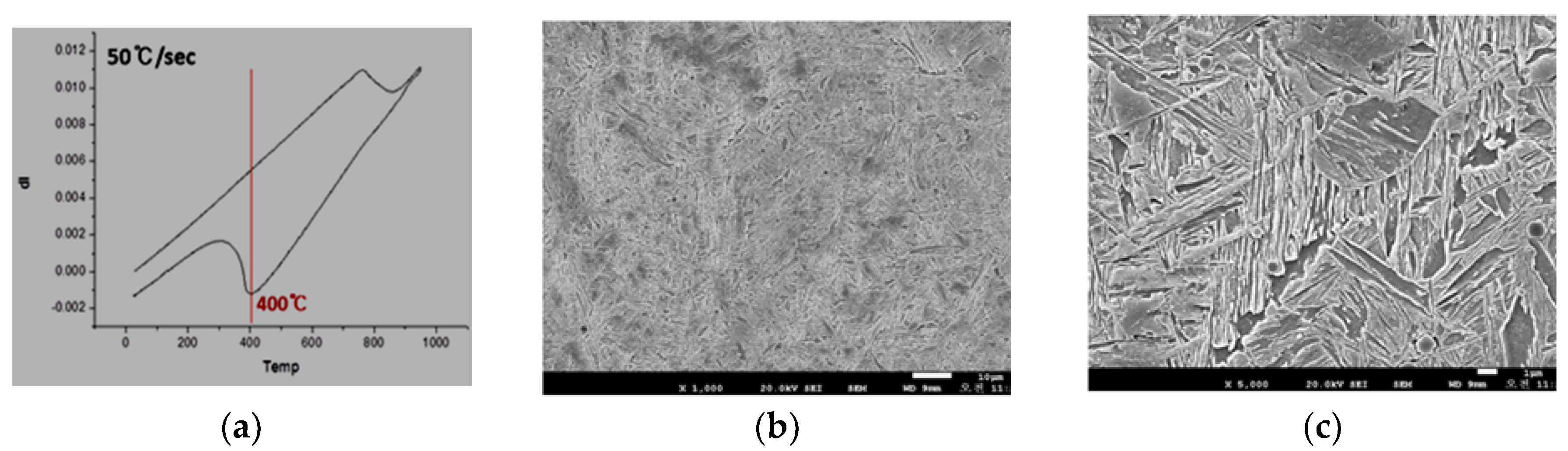
To investigate phase transformation behavior of weld metal under various cooling rates, 0.1~50 °C/s, a dilatometer (Theta, New Castle, DE, USA) measuring the length change of the specimens (φ4, length 10) was used. The length change can be caused by both the thermal expansion and the phase transformation. The latter gives an abrupt length change, so the phase transformation temperature can be found. After heating from 25 °C to 950 °C and cooling to 25 °C, microstructures were observed using scanning electronic microscope (SEM) (JEOL JSM-5900, Peabody, USA. Figure 1 shows the length change at cooling rate 0.1 °C/s, and the microstructures observed at 1000× and 5000× magnification at room temperature. Ferrite (Black) accounted for the majority. The rest was a small amount of martensite and bainite. When the austenitic specimen at 950 °C cooled down, the ferrite started to be generated near 710 °C. The polygonal ferritic grains were quite large in size. When the temperature of the specimen was about 380 °C, the residual austenite was transformed into bainite. At lower temperatures, martensite was obtained. The Vickers hardness was 277 Hv. Figure 2 shows the results at a cooling rate of 0.5 °C/s. It was found that the thermal expansion curve was different from the curve at cooling speed of 0.1 °C/s, and the ferritic and bainitic structures were finer compared to those at 0.1 °C/s. The ferrite and bainite accounted for the majority, and the amount of martensite slightly increased. The Vickers hardness was 298 Hv. Figure 3 shows the results at a cooling rate of 1.0 °C/s. The fraction of ferrite decreased very much, on the other hand, the fraction of the martensite increased significantly. The bainitic structure became even finer, because more nuclei of phase transformation were generated due to rapid cooling rate. The Vickers hardness of the specimen, 331 Hv was larger than the hardness 277 Hv at a cooling rate of 0.1 °C/s. Figure 4 presents the results at cooling rates of 3 °C/s. The specimen was composed of bainite and martensite, and the microstructures were much finer. The Vickers hardness was 362 Hv. Figure 5 is the results at cooling rates of 10 °C/s. The specimen was composed of bainite and martensite, and the microstructures were much finer. The Vickers hardness was 390 Hv. Figure 6 is the results at cooling rates of 20 °C/s. Most was martensitic, and the bainite was a little. At the martensitic transformation temperature, 400 °C, the length of the specimen suddenly decreased. The Vickers hardness was 430 Hv. Figure 7 shows the results at cooling rates of 50 °C/s. The microstructure was almost 100% martensite. At the martensitic transformation temperature, 400 °C the length of the specimen suddenly decreased. The hardness of the specimen was 445 Hv. It was found that the Vickers hardness increased with cooling rates, and to obtain microstructures composed of martensite and bainite, cooling rate must be lower than 3.0 °C/s.
2.2. Restoration Process of Full-Size Worn Wheels
The process of restoring worn-out wheels by submerged arc welding is shown in Figure 8. First, a target wheel was visually inspected to find surface defects. If no severe defects were found, after an acid rinse of the surface, a more accurate defect inspection was carried out using an ultrasound and magnetic particle inspection. The next step was preheating. The wheel was heated to 300 °C at 50 °C/h and maintained at that temperature for one hour. Then the wheel was moved to the welding site. A φ2.0 welding wire with C 0.06 wt.%, Mn 2.37, Si 1.38, Cr 0.90, Ni 0.53, Ti 0.026, V 0.06 was used for the submerged arc welding at temperatures above 160 °C. The hardness of the welding wire was 280–283 HRc. After welding, the wheel was moved to a furnace at 300 °C, then cooled to 260 °C by natural cooling. From 260 to 100 °C the wheel was cooled at a rate of 40 °C/h or less by operating the cooling fan, then taken out from the furnace. To check welding defects, ultrasound testing and magnetic particle testing were performed. Finally the welded wheel was machined into the specified profile. Figure 8c,d shows the samples welded on the flange and on both the tread and the flange, respectively.
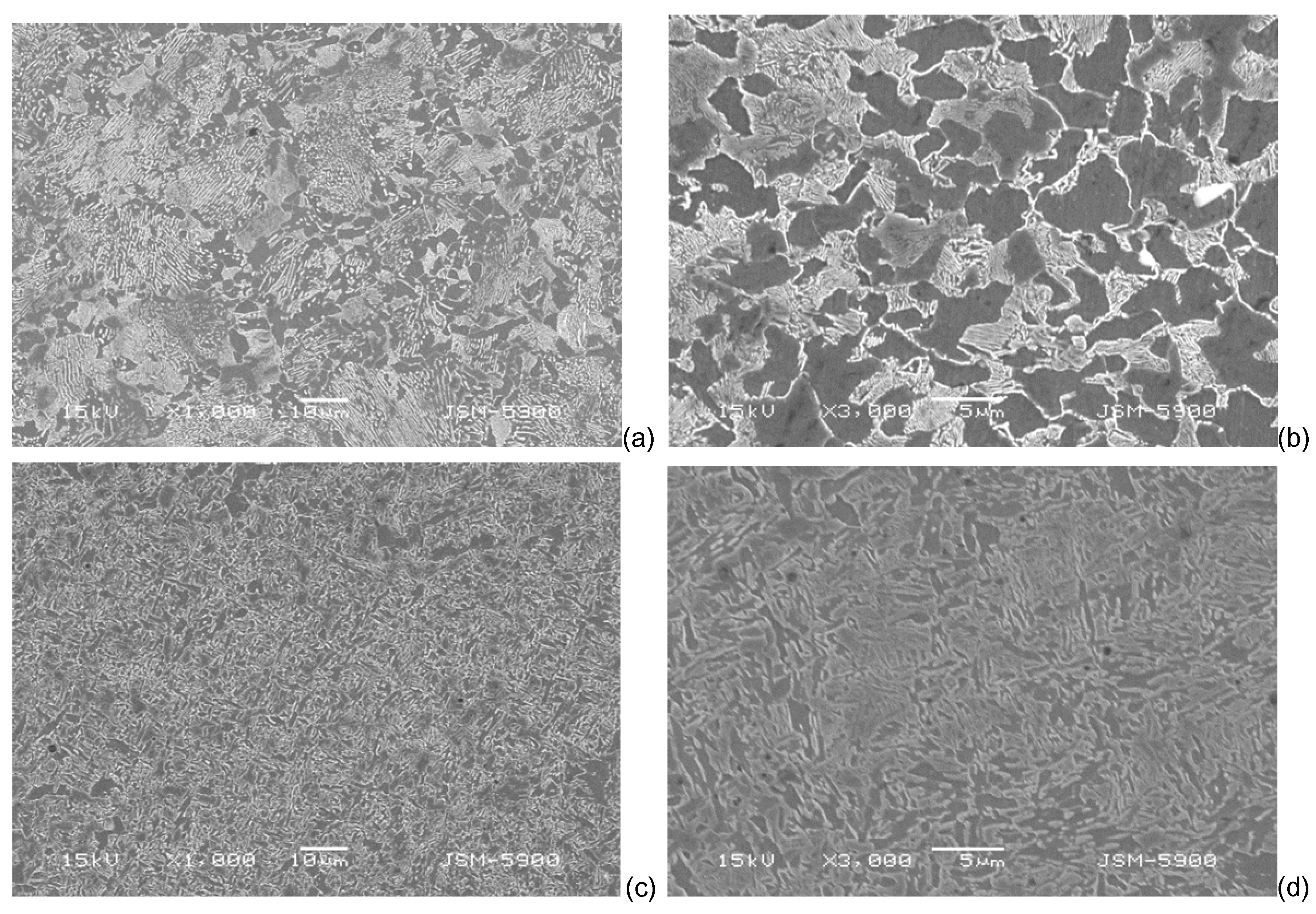
Figure 9 represents the micrographs taken by scanning electronic microscope In the SEM photographs, the black part is ferritic. It was found that the fusion zone was composed of bainitic microstructures (See Figure 7 in [14]), which was expected.
Tensile specimens with a diameter of 8 mm and a length of 90 mm (gauge length 40) were taken from the weld metal of the wheel (Figure 8d). The measured tensile properties are given in Table 2. YS0.2% indicates the 0.2% offset yield stress; UTS, the ultimate tensile stress; , the elongation rate; R.A., the rate of reduction area. The values satisfied the international standard for railway wheels, BS EN 13262+A1:2009-01. Compact tension fracture toughness specimens with a thickness of 30 mm (ASTM E399 standard) were produced from the rim of the welded wheel (Figure 8d). It was confirmed that the specimen satisfied the conditions of linear elastic fracture mechanics according to the ASTM E399 standard. The fracture toughness of the weld metal, was 64.85 MPa at 20 °C, which was a little lower than the minimum value, 70 MPa specified in the EN 13262+A1 standard, Rockwell hardness values measured in the weld metal, HAZ, and base material were 62.5, 57.7, and 51.3 HRA, respectively. The Brinell hardness number in the weld metal was 321 HB. The content of nonmetallic inclusions was determined in two specimens taken from the weld metal according to the ISO 4967:2013(E) method A. In this method, the shapes of inclusions examined at 100x magnification of 0.5 mm2 were compared with the reference inclusion images. A metallurgical microscope (Olympus BX51M, Tokyo, Japan) was used. The index number for each inclusion is shown in Table 3, which satisfies the micrographic cleanness specified in the international standard for railway wheels (BS EN 13262+A1:2009-01).
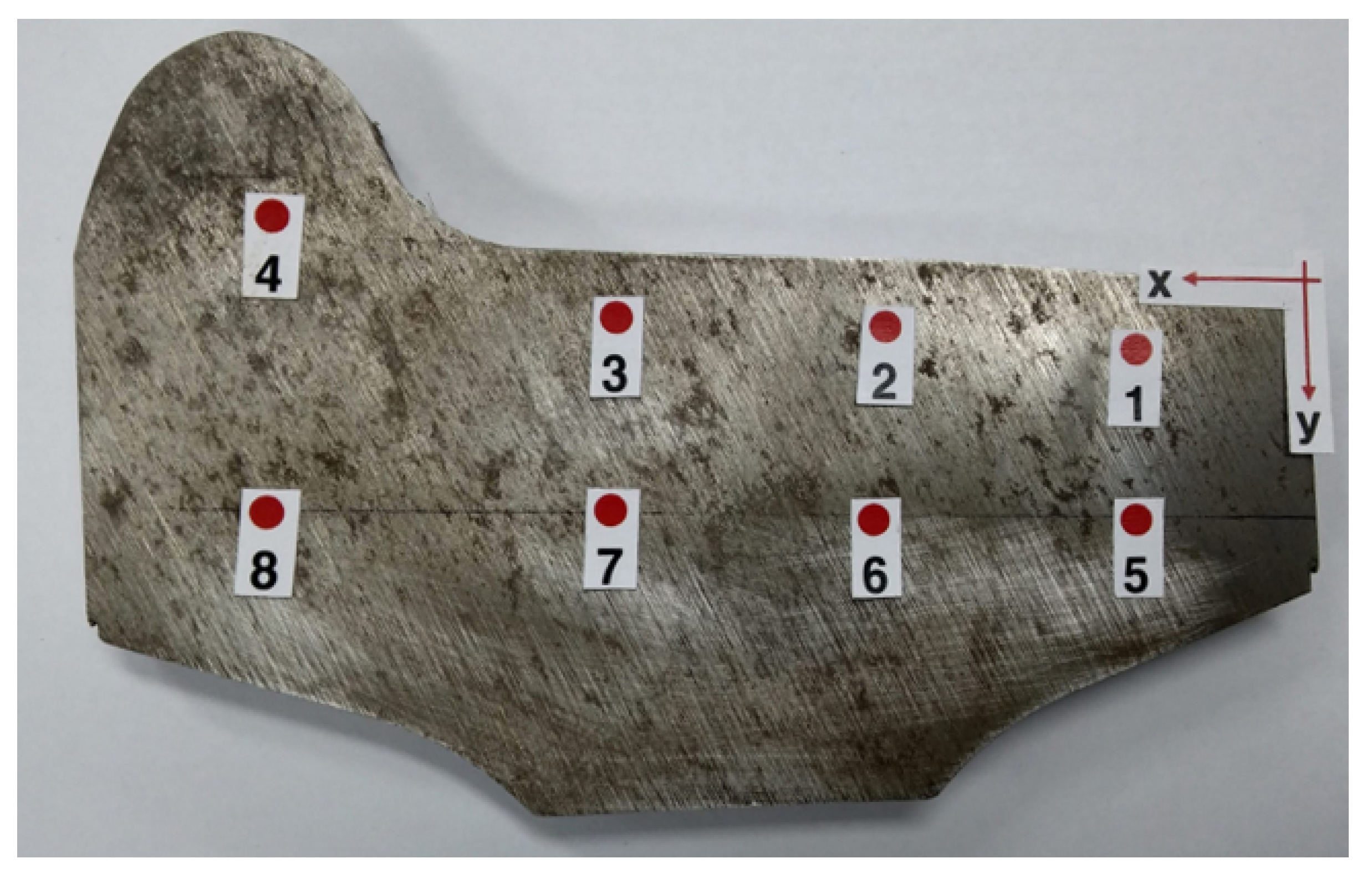
Residual stress is also one of the factors to be examined. There are many residual stress measuring techniques [15] such as Barkhausen noise method, X-ray diffraction method, neutron diffraction method, ultrasonic method, hole drilling technique, ring-core method, deep-hole method, sectioning technique, contour method, etc. Each method has disadvantages and advantages. In this study, residual stresses on the wheel section in the radial direction were measured using the X-ray diffraction residual stress analyzer with Cr tube installed (wave length λ = 2.291 Å) (μ-X360s, Pulstec, Hamamatsu, Japan), which uses the cos α method. This method captures diffracted X-ray beam by a 2 dimensional detector, so measurement is faster and more convenient than the traditional sin2ψ method, which detects diffracted X-ray beam by line detectors. Delbergue et al. [16] and Lee et al. [17] showed that the cos α method provides a better measurement repeatability than the sin2ψ method. Figure 10 and Table 4 show the measuring points and measured residual stresses, σx and σy. The σx values ranged from −21~−256 MPa. The σy values ranged from −256~+86 MPa. Young modulus, 224 GPa, and Poisson ratio, 0.28 were used. According to the experimental results by Neslušan et al. [18], who measured the residual stress in the radial section of a wagon wheel using X-ray diffraction method, the residual stress ranged from −300 to −100 MPa for the wheel subjected to six years of operation. Nejad [19] simulated quenching and annealing process of a railway wheel using finite element method and obtained residual stress. Stress components on the wheel tread were in the range of −60~−330 MPa. Comparing the above three cases, the residual stresses occurring in the overlay welding are not likely to be a problem in application.
3. Results and Discussion
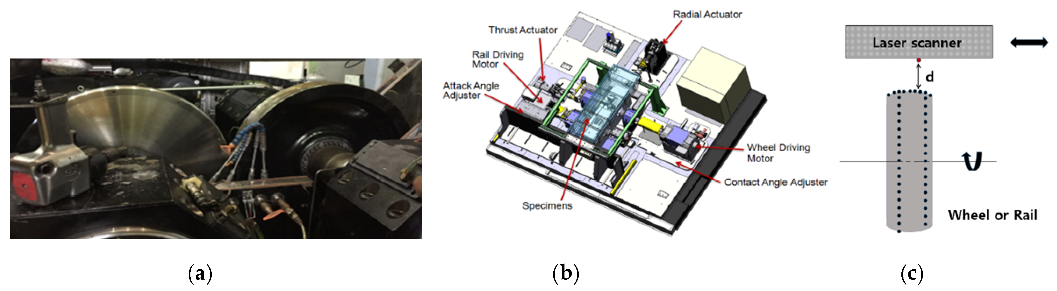
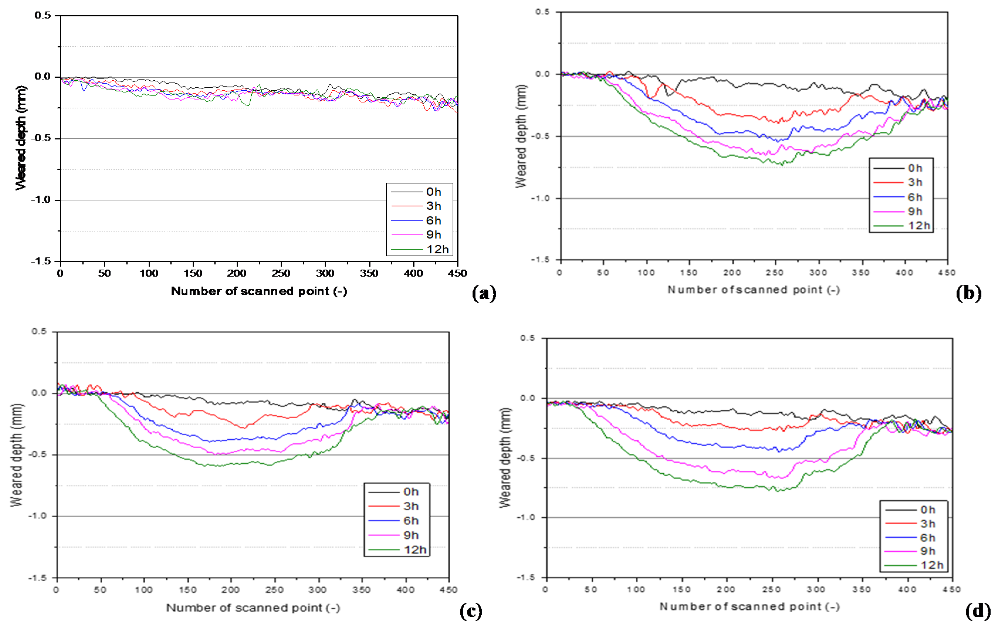
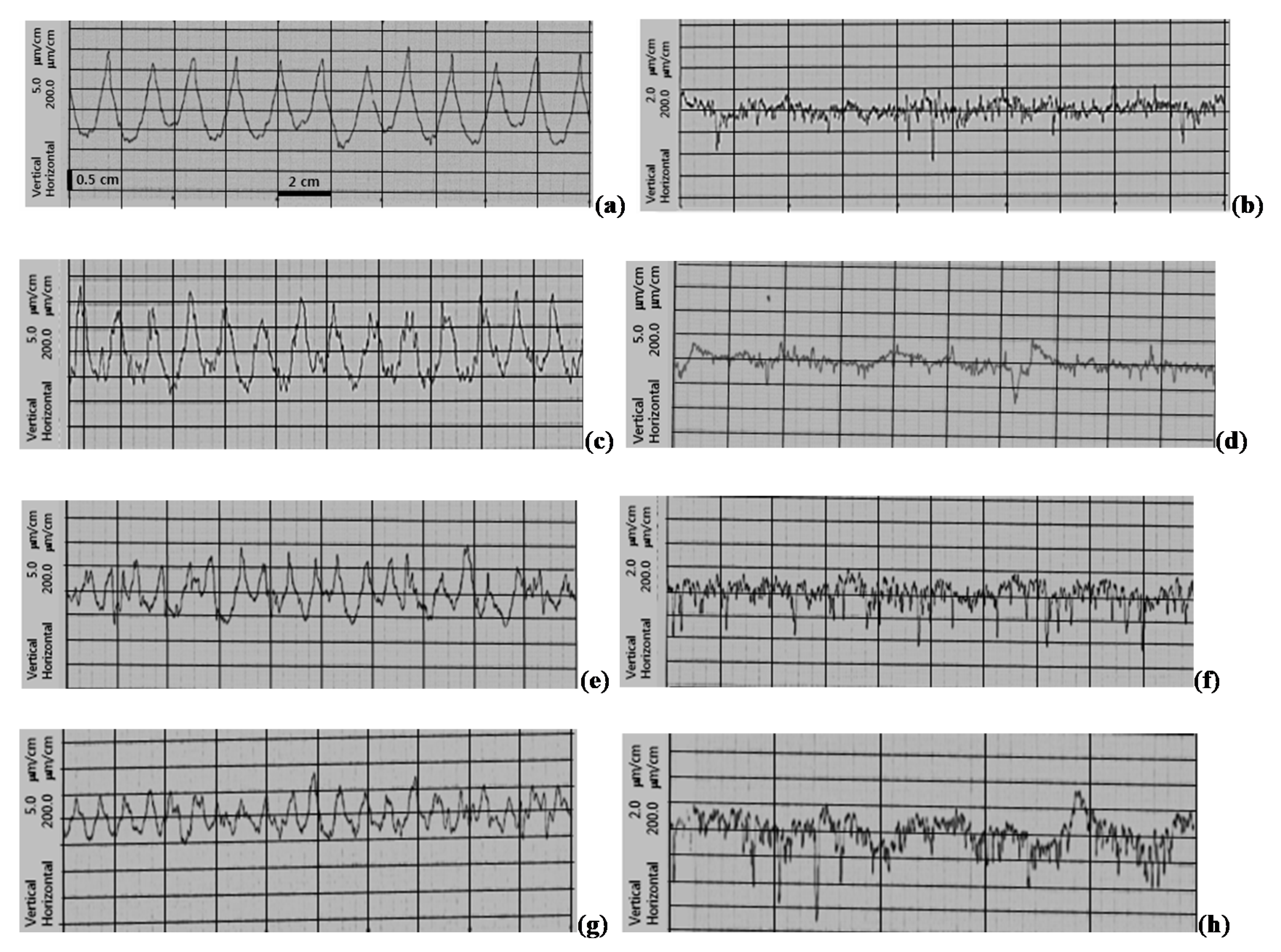
It was confirmed that the process of restoring worn wheels by submerged arc welding produced an expected bainitic alloy, whose mechanical properties seemed to be practically applicable. So as a next step, a full scale wear test was carried out using a wheel/rail rolling wear tester. Figure 11 shows the test equipment. The wheel disc and the rail disc are driven by independent motors, so slip between the two discs can be controlled. The available diameter of the discs is 300–1000 mm. The maximum rotation speed is 2360 rpm. In this study, the two discs had a diameter of 820 mm. the rail disc had a contact width of 21 mm and a radius of curvature 300 mm (convex tread). Four rail discs were made of UIC rail material [20]. Three wheel discs were produced as described in the previous section (Figure 8d) without the flange, and a new wheel disc was prepared from a commercial wheel by machining. The contact width of the wheel disc was 135 mm. The axial loading was applied using a radial actuator. The initial contact stress was 800 MPa according to the Hertz contact theory. The rotating speeds of the rail disc and wheel disc were 505 and 520.2 rpm, respectively (2% slip rate). 4 pairs of wheel/rail discs were tested for 12 h under the above-mentioned conditions. Wear depth was measured using a laser scanner installed above the two wheels at the end of 3, 6, 9, and 12 h from the start of the test. Figure 11c shows the wear depth measurement method. When the test was suspended, the laser scanner measured the vertical distance, d, from the laser point to the 450 points on the wheel tread by moving the scanner horizontally. The measurement continued while rotating the wheel by one degree steps. The average vertical distance of 360 circumferentially-measured values was used to obtain the wheel tread profile in Figure 12. Three repaired wheels showed similar profiles. For the new wheel, the maximum wear depth (the current distance minus the initial distance) was 0.12 mm at the end of 12 h. For the repaired wheels, the maximum wear depth was about 0.65 mm. It was found that the wear depth was less than half of the wear depth of the weld-repaired wheel, which were weld-repaired, but had ferritic–pearlitic microstructures [21]. No defects were detected on the surfaces of the wheel and rail discs. Cracks on the wheel surface occur due to severe deformation, ratchetting, surface defects, and rolling contact fatigue, etc., and may propagate into the wheel. An appropriate level of wear can remove initial surface cracks before they grow to a critical length. Therefore, it is not always good for the wheel material to have great resistance to wear. Optimal wear resistance is needed for railway wheel materials. Figure 13 represents the surface roughness profiles measured (Mitutoyo Surftest SJ-301, Kawasaki, Japan) along the axle direction on the wheel tread. Before the test the surfaces showed regular patterns due to machining. For the new wheel before and after the test, the roughness value changed from 2.4 to 0.24 in Ra (arithmetical mean deviation of roughness) scale. For the repaired wheels, the roughness value changed from 1.73 to 0.46.
4. Conclusions
It was found that the process developed for restoring worn wheels using the submerged arc welding successfully produced an expected bainitic alloy in the weld metal. The composition of the welding wire (C 0.06 wt.%, Mn 2.37, Si 1.38, Cr 0.90, Ni 0.53, Ti 0.026, V 0.06) and post-weld heat treatment played important roles. It was found that the Vickers hardness increased with cooling rates, and to obtain microstructures composed of martensite and bainite, cooling rate must be lower than 3.0 °C/s. The tensile strength was 1074 MPa, elongation rate 23%, and Charpy impact energy 53 J, which satisfied the standard for commercial wheels. The weld metal also satisfied the micrographic cleanness specified in the International standard for railway wheels (BS EN 13262+A1:2009-01). The residual stress measured by the X-ray refraction method ranged from −256 MPa to +86 MPa. The full scale rolling wear test showed that the wear depth of the weld-repaired wheel with bainitic micro structure was much greater than that of the commercial wheel, but it was less than half of the wear depth of the weld-repaired wheel with ferritic–pearlitic microstructures. Considering the compromise between resistance to wear and resistance to rolling contact fatigue crack propagation, the wear resistance of the welding-repaired flange seemed to be appropriate, and the developed process could be very useful in industry and in future research.
Author Contributions
Y.-J.L. contributed to the specimen preparation; residual stress measurement. B.-C.C. contributed to draft preparation; microscopic examination; writing review and editing; wear test. All authors have read and agreed to the published version of the manuscript.
Funding
This research received no external funding.
Acknowledgments
The authors are grateful to the Korea Railroad Research Institute, and the Chungbuk Techno-Park for the financial support of this research.
Conflicts of Interest
The authors declare no conflict of interest.
References
- Selvi, S.; Sankaran, S.; Srivatsavan, P.R. Comparative study of hardfacing of valve seat ring using MMAW process. J. Mater. Process. Technol. 2008, 207, 356–362. [Google Scholar] [CrossRef]
- Bayhan, Y. Reduction of wear via hardfacing of chisel ploughshare. Tribol. Int. 2006, 39, 570–574. [Google Scholar] [CrossRef]
- Fernandez, J.E.; Vijande, R.; Tucho, R.; Rodriguez, J.; Martin, A. Materials selection to excavator teeth in mining industry. Wear 2001, 250, 11–18. [Google Scholar] [CrossRef]
- Singla, S.; Kang, A.S.; Grewal, J.S.; Cheema, G.S. Wear behavior of weld overlay on excavator bucket teeth. Procedia Mater. Sci. 2014, 5, 256–266. [Google Scholar] [CrossRef] [Green Version]
- Eremin, E.N.; Losev, A.S. Wear resistance increase of pipeline valves by overlaying welding flux-cored wire. Procedia Eng. 2015, 113, 435–440. [Google Scholar] [CrossRef] [Green Version]
- Malinov, V.L.; Malonov, L.S.; Golyakevich, A.A.; Orlov, L.N. Improving the endurance of crane wheels using new flux-cored wire Veltek-N285C. J. Weld. Int. 2016, 30, 880–883. [Google Scholar] [CrossRef]
- Anan’ev, S.P.; Korotkov, V.A.; Goloviznin, B.L.; Kozlov, V.V. Improving the technology for hardfacing crane wheels. J. Weld. Int. 2007, 21, 534–537. [Google Scholar] [CrossRef]
- Gorunov, A.I. Complex refurbishment of titanium turbine blades by applying heat-resistant coatings by direct metal deposition. Eng. Fail. Anal. 2018, 86, 115–130. [Google Scholar] [CrossRef]
- Gajvoronsky, A.A.; Poznyakov, V.D.; Sarzhevsky, V.A.; Vasiliev, V.G.; Orlovsky, V.Y. Influence of thermo-deformational cycle of hardfacing on the structure and properties of railway wheels at their reconditioning. Paton Weld Sci. Tech. 2010, 5, 15–18. [Google Scholar]
- Markisha, L.I.; Poznyakov, V.D.; Gajvoronsky, A.A.; Berdinkova, E.N.; Alekseenko, T.A. Structure and properties of railway wheel surface after restoration surfacing and service loadin. Paton Weld. J. 2015, 5–6, 96–100. [Google Scholar] [CrossRef] [Green Version]
- Mendez, P.F.; Barnes, N.; Bell, K.; Borlea, S.D.; Gajapathi, S.S.; Guest, S.D.; Izadi, H.A.; Gol, K.; Wood, G. Welding processes for wear resistant overlays. J. Manuf. Process 2014, 16, 4–25. [Google Scholar] [CrossRef]
- Gianni, A.; Ghidini, A.; Karlsson, T.; Ekberg, A. Bainitic steel grade for solid wheels: Metallurgical, mechanical, and in-service testing. Proc. Inst. Mech. Eng. Part F J. Rail Rapid Transit 2009, 163–171. [Google Scholar] [CrossRef]
- KS R 9221:2008. Wheels for Railway Rolling Stock; Korean Industrial Standards: Seoul, Korea, 2008. [Google Scholar]
- Lee, K.M.; Polycarpou, A.A. Wear of conventional pearlitic and improved bainitic rail steels. Wear 2005, 259, 391–399. [Google Scholar] [CrossRef]
- Rossini, N.S.; Dassisti, M.; Olabi, A.G. Methods of measuring residual stresses in components. Mater. Des. 2012, 35, 572–588. [Google Scholar] [CrossRef] [Green Version]
- Delbergue, D.; Texier, D.; Lévesque, M.; Bocher, P. Comparison of two X-ray residual Stress measurement methods: Sin2 ψ and cos α, through the determination of a martensitic steel X-ray elastic constant. Mater. Res. Proc. 2016, 2, 55–60. [Google Scholar] [CrossRef] [Green Version]
- Lee, S.Y.; Ling, J.; Wang, S.; Ramirez-Rico, J. Precision and accuracy of stress measurement with a portable X-ray machine using an area detector. J. Appl. Crystallogr. 2017, 50, 131–144. [Google Scholar] [CrossRef] [Green Version]
- Neslušan, M.; Minárik, P.; Grenčík, J.; Trojan, K.; Zgútová, K. Non-destructive evaluation of the railway wheel surface damage after longterm operation via Barkhausen noise technique. Wear 2019, 420–421, 195–206. [Google Scholar] [CrossRef]
- Nejad, R.M. Using three-dimensional finite element analysis for simulation of residual stresses in railway wheels. Eng. Fail. Anal. 2014, 45, 449–455. [Google Scholar] [CrossRef]
- UIC 860 Technical Specification for the Supply of Rails, 9th ed.; International Union of Railways: Paris, France, 2008.
- Goo, B.C.; Hwang, S.H.; Choi, S.Y.; Lee, Y.J. Worn-wheel restoration by welding and evaluation of mechanical properties. J. Korean Soc. Railw. 2018, 21, 241–248. [Google Scholar] [CrossRef]
Figure 1.
(a) Length change of the specimen vs. temperature at cooling rate 0.1 °C/s, (b) SEM image ×1000, (c) SEM image ×5000.
Figure 1.
(a) Length change of the specimen vs. temperature at cooling rate 0.1 °C/s, (b) SEM image ×1000, (c) SEM image ×5000.

Figure 2.
(a) Length change of the specimen vs. temperature at cooling rate 0.5 °C/s, (b) SEM image ×1000, (c) SEM image ×5000.
Figure 2.
(a) Length change of the specimen vs. temperature at cooling rate 0.5 °C/s, (b) SEM image ×1000, (c) SEM image ×5000.

Figure 3.
(a) Length change of the specimen vs. temperature at cooling rate 1.0 °C/s, (b) SEM image ×1000, (c) SEM image ×5000.
Figure 3.
(a) Length change of the specimen vs. temperature at cooling rate 1.0 °C/s, (b) SEM image ×1000, (c) SEM image ×5000.

Figure 4.
(a) Length change of the specimen vs. temperature at cooling rate 3.0 °C/s, (b) SEM image ×1000, (c) SEM image ×5000.
Figure 4.
(a) Length change of the specimen vs. temperature at cooling rate 3.0 °C/s, (b) SEM image ×1000, (c) SEM image ×5000.

Figure 5.
(a) Length change of the specimen vs. temperature at cooling rate 10 °C/s, (b) SEM image ×1000, (c) SEM image ×5000.
Figure 5.
(a) Length change of the specimen vs. temperature at cooling rate 10 °C/s, (b) SEM image ×1000, (c) SEM image ×5000.

Figure 6.
(a) Length change of the specimen vs. temperature at cooling rate 20 °C/s, (b) SEM image ×1000, (c) SEM image ×5000.
Figure 6.
(a) Length change of the specimen vs. temperature at cooling rate 20 °C/s, (b) SEM image ×1000, (c) SEM image ×5000.

Figure 7.
(a) Length change of the specimen vs. temperature at cooling rate 50 °C/s, (b) SEM image ×1000, (c) SEM image ×5000.
Figure 7.
(a) Length change of the specimen vs. temperature at cooling rate 50 °C/s, (b) SEM image ×1000, (c) SEM image ×5000.

Figure 8.
(a) Restoration process of worn wheels by submerged arc welding, (b) Semi-automatic welding, (c) Sample welded on the flange, (d) Sample welded on both the tread and the flange.
Figure 8.
(a) Restoration process of worn wheels by submerged arc welding, (b) Semi-automatic welding, (c) Sample welded on the flange, (d) Sample welded on both the tread and the flange.
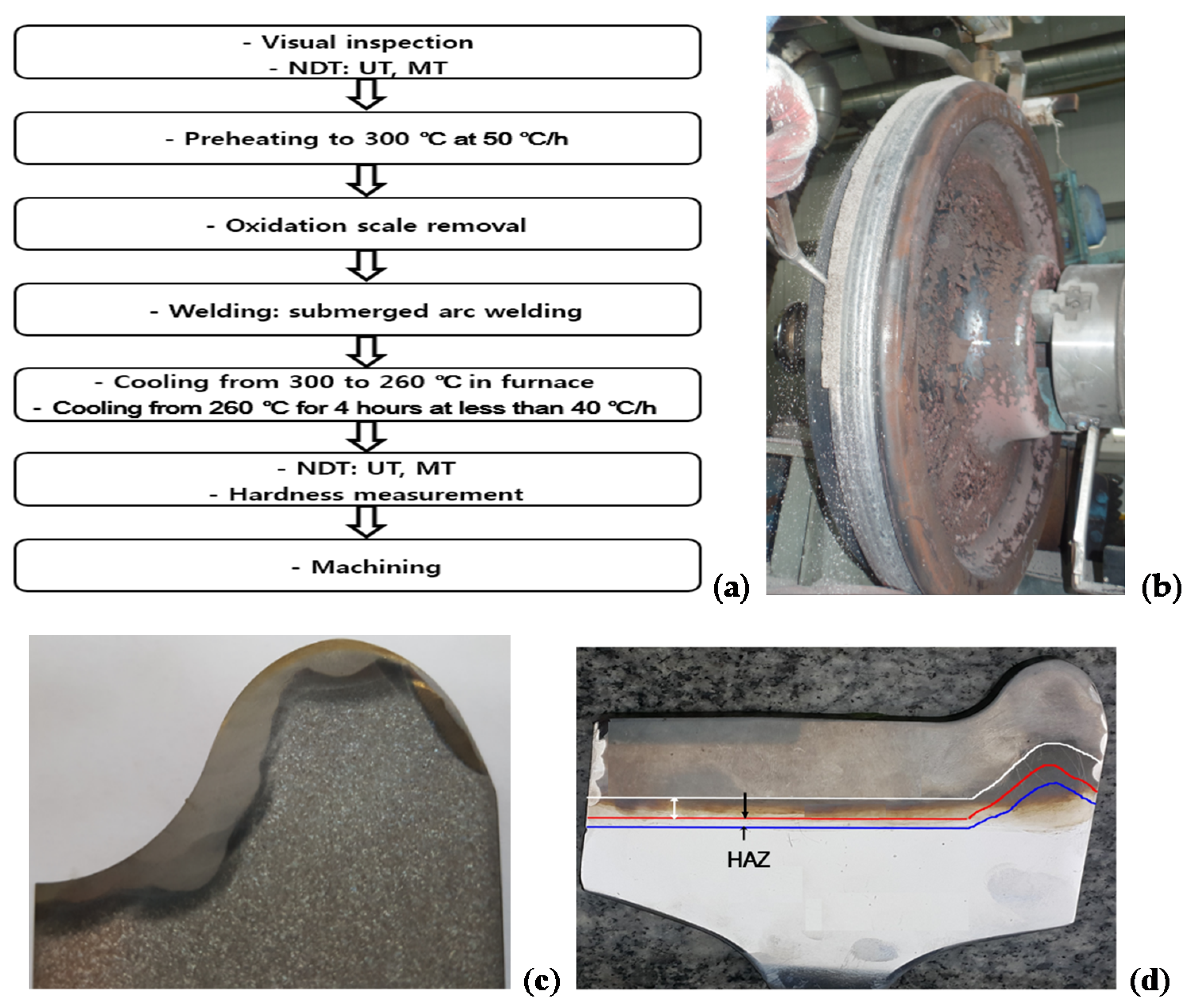
Figure 9.
(a) SEM photographs of the base material, (b) Heat-affected zone (HAZ), (c) Fusion zone (×1000), (d) Fusion zone (×3000).
Figure 9.
(a) SEM photographs of the base material, (b) Heat-affected zone (HAZ), (c) Fusion zone (×1000), (d) Fusion zone (×3000).

Figure 10.
Points to measure residual stress by the X-ray diffraction method.

Figure 11.
(a) Photograph of the rolling contact wear tester, (b) Schema, (c) Wear depth measuring laser scanner.
Figure 11.
(a) Photograph of the rolling contact wear tester, (b) Schema, (c) Wear depth measuring laser scanner.

Figure 12.
(a) Wear depth of the commercial wheel disc, (b) Restored wheel disc #1, (c) Restored wheel disc #2, (d) Restored wheel disc #3.
Figure 12.
(a) Wear depth of the commercial wheel disc, (b) Restored wheel disc #1, (c) Restored wheel disc #2, (d) Restored wheel disc #3.

Figure 13.
(a) Surface roughness before the wear test of the commercial wheel disc, (b) After the test of the commercial wheel disc, (c) Before the test of the restored wheel disc #1, (d) After the test of the restored wheel disc #1, (e) Before the test of the restored wheel disc #2, (f) After the test of the restored wheel disc #2, (g) Before the test of the restored wheel disc #3, (h) After the test of the restored wheel disc #3.


Table 1.
Compositions of the wheel, welding wire and weld metal (wt.%).
| Type | C | Si | Mn | P | S | Cr | Ni | Al | Ti | N | V | Cu |
|---|---|---|---|---|---|---|---|---|---|---|---|---|
| Wheel | 0.67 | 0.15 | 0.7–0.9 | 0.045 | 0.045 | - | - | - | - | - | - | 0.35 |
| Welding wire | 0.06 | 1.38 | 2.37 | - | - | 0.90 | 0.53 | - | 0.026 | - | 0.06 | - |
| Weld metal | 0.185 | 1.05 | 1.88 | 0.016 | 0.011 | 0.706 | 0.442 | 0.018 | 0.036 | 0.0091 | 0.042 | 0.05 |
Table 2.
Tensile properties of the specimen prepared from the weld metal.
| YS0.2% (MPa) | UTS (MPa) | (%) | R.A. (%) | E (MPa) | Tem (°C) |
|---|---|---|---|---|---|
| 821 | 1074 | 23 | 49 | 201542 | 20 |
Table 3.
Index for the nonmetallic inclusion content of the weld metal according to ISO 4967.
| Specimen | Group A | Group B | Group C | Group D | Group DS | ||||
|---|---|---|---|---|---|---|---|---|---|
| Sulfide Type | Aluminate Type | Silicate Type | Globular Oxide Type | Single Globular Type | |||||
| Thin | Thick | Thin | Thick | Thin | Thick | Thin | Thick | - | |
| No. 1 | 0.5 | 0.0 | 0.0 | 0.0 | 0.5 | 0.0 | 1.5 | 0.5 | 1.5 |
| No. 2 | 0.0 | 0.0 | 1.0 | 0.0 | 0.0 | 0.0 | 1.5 | 0.5 | 1.5 |
Table 4.
Residual stresses measured at 8 points shown in Figure 11.
Table 4.
Residual stresses measured at 8 points shown in Figure 11.
| Point | #1 | #2 | #3 | #4 | #5 | #6 | #7 | #8 |
|---|---|---|---|---|---|---|---|---|
| (x, y) | (20, 8) | (50, 8) | 80, 8) | (120, −3) | (20, 30) | (50, 30) | (80, 30) | (120, 30) |
| σx (MPa) | −176 | −209 | −41 | −21 | −256 | −183 | −237 | −107 |
| σy (MPa) | −187 | −225 | +36 | +86 | −256 | −132 | −196 | −35 |
© 2020 by the authors. Licensee MDPI, Basel, Switzerland. This article is an open access article distributed under the terms and conditions of the Creative Commons Attribution (CC BY) license (http://creativecommons.org/licenses/by/4.0/).
Share and Cite
MDPI and ACS Style
Coo, B.-C.; Lee, Y.-J. Railway Vehicle Wheel Restoration by Submerged Arc Welding and Its Characterization. Sci 2020, 2, 33. https://doi.org/10.3390/sci2020033
AMA Style
Coo B-C, Lee Y-J. Railway Vehicle Wheel Restoration by Submerged Arc Welding and Its Characterization. Sci. 2020; 2(2):33. https://doi.org/10.3390/sci2020033
Chicago/Turabian StyleCoo, Byeong-Choo, and Young-Jin Lee. 2020. "Railway Vehicle Wheel Restoration by Submerged Arc Welding and Its Characterization" Sci 2, no. 2: 33. https://doi.org/10.3390/sci2020033