Enhancing Surgical Tool Performance with Alumina-Based Coatings: An Engineering Analysis
by
 , , , and
Cristiano Fragassa
1,2 ,
,
Giovanni Pappalettera
3 ,
,
Vincenzo Moramarco
3,
Ana Pavlovic
1 and
Marco Arru
1,2,* 1
Department of Industrial Engineering, University of Bologna, Viale del Risorgimento 2, 40136 Bologna, Italy
2
Artesia Technologies s.r.l., Via Bruno Tosarelli, 300, Villanova, 40055 Bologna, Italy
3
Department of Mechanics, Mathematics & Management, Polytechnic of Bari, Via Orabona 4, 70125 Bari, Italy
*
Author to whom correspondence should be addressed.
Sci 2024, 6(2), 24; https://doi.org/10.3390/sci6020024
Submission received: 23 March 2024
/
Revised: 15 April 2024
/
Accepted: 17 April 2024
/
Published: 19 April 2024
(This article belongs to the Section Thermal Engineering and Sciences)
Abstract
:The present study investigates the utilization of ceramic coatings and insulation elements in the context of Cold Atmospheric Pressure Plasma (CAPP) surgery tools, highlighting how precise engineering modifications can influence surgical precision. The adoption of cold plasma in surgery can be reinforced by material advancements withstanding several specific challenges, including electrical and thermal protection. We explore the potential of alumina (Al2O3), renowned for its high dielectric strength and resistance, as a promising material solution for insulating electrodes. We evaluated the thermal performance of surgical tools concerning different insulation thicknesses. Our findings suggest that Al2O3–based coatings, with their superior characteristics, significantly enhance the usability of cold plasma technology, thus fostering its application in minimally invasive surgery. We examine the implications of these findings for the design of next-generation surgical instruments and propose avenues for future research. This work contributes to the field of biomedical engineering by showcasing the pivotal role of material science in advancing surgical technologies.
1. Introduction
Surgical practices have a long history of embracing new technologies to improve patient care. From the earliest use of tools to cut into the body to significant advancements like fighting infections, sterilizing instruments, and using anesthesia, surgery has always been evolving [1]. However, managing bleeding during operations has been a challenge. This led to the development of electrosurgery, a method that uses electrical currents to cut tissue and stop bleeding. Despite its benefits, electrosurgery can cause complications like delayed healing or scars due to the heat generated [1].
In response, newer technologies have been introduced. For example, surgical lasers and ultrasound devices offer more precision and less damage to surrounding tissues, but they also have their limitations, such as specific use cases and potential risks like burns from laser light.
One quite recent innovation in surgery is the use of so-called Cold Atmospheric Pressure Plasma (CAPP), or for short, “cold plasma” technology [2]. This uncommon approach utilizes ionized air to generate cold plasma from ambient air.
Traditionally employed for various medical treatments such as sterilization and coagulation, it can also be utilized in surgery. In this application, tissues are treated without the heat damage typically associated with electrosurgery, resulting in less post-operative pain, faster healing, and reduced scarring.
Despite the literature being rather limited in the case of air plasma technology, for electrosurgery a large collection of studies offer an in-depth analysis of development, obstacles, and progress, emphasizing the crucial role of innovation in improving safety measures for minimally invasive surgeries, focusing on specific aspects such as the following:
- Injury prevention, as in [3] that provides a comprehensive overview of electrosurgery’s principles, differentiating between monopolar and bipolar currents, and direct and alternating currents, and detailing the use and effects of cut and coagulation currents. It also discusses potential injuries from electrosurgery, including alternate path burns and patient electrode burns, underscoring the complexity of electrosurgery and the need for clinician education to prevent injuries.
- Electrosurgical injuries, as in [4] that investigates the hypothesis that electrical burns in the genital tract and urethral strictures might be caused by capacitive coupling and stray currents from both intact and defective electrodes. It found that 20–25% of the current was induced by capacitive coupling to the resectoscope sheath, leading to the conclusion that such coupled currents can cause thermal injuries during prolonged resectoscopic surgery, and that stray currents from defective insulation can result in significant burns.
- Invisible risks, as in [5] that outlines the evolution of electrosurgical units (ESUs) and introduces key technological advancements like isolated output ESUs, Contact Quality Monitoring (CQM) circuitry, and Active Electrode Monitoring (AEM) systems that have significantly improved patient safety by addressing risks such as alternate site burns, insulation failure, and capacitive coupling. It emphasizes the need for advanced solutions to protect against “invisible” risks and highlights the importance of understanding electrosurgery’s biophysics for safer surgical practices.
- Insulation failures in electrosurgical instruments, as in [6] that focuses on the significant issue of insulation failures (IFs) in electrosurgical instruments, which can lead to unintended burns and complications. Through testing with high-voltage detectors, the study highlights the insufficiency of routine visual inspections and underlines the necessity for comprehensive testing protocols to identify and mitigate instrument defects.
They also highlight the strict relationships existing in electrosurgery between technological advancements, instrument developments, risks, and complications, especially related to precision surgery and minimally invasive procedures [7]. In the case of insulation with respect to high temperatures or high voltages, they underscore the critical importance of continual technological innovation and rigorous testing protocols to ensure the safety and efficacy of electrosurgical procedures.
The present paper intends to move in this direction and represents an evolution on a preliminary investigation, recently proposed by (some of) the authors in [8]. Atmospheric pressure air plasma technology in surgical applications also exploded in this first case, but with respect to different test methods and surgery targets as follows: (a) using a laser pyrometer instead of a thermal imager; (b) detecting temperatures on individual points instead of large areas; (c) in static conditions (an electrode stationary on a point) and non-dynamic conditions (sliding of the electrode on the substrate); (d) focusing attention on heating the metal without investigating the effect of different materials or insulations; (e) referring to medical tools relating to external (scalpel) and not internal (endoscopic probes) surgery.
Despite such relevant differences, key findings can be mentioned as follows:
- Atmospheric pressure air plasma technology can transfer energy from plasma-generator devices to human/non-human tissue with minimal heating, which is beneficial for surgical treatments. Notably, temperatures on tissues remaining stably low.
- Temperature profiles during operations vary greatly depending on the physical conditions of the system and uses. They can be conveniently investigated by experiments but also modified by tool design changes, permitting potential improvements in surgical devices and treatments.
However, a simplified approach can be assumed here, moving to a purely engineering discussion: if the limited adoption of cold plasma technology is due to the potential for electrodes to damage tissues through heat or electric discharges, introducing insulation solutions could mitigate this issue.
As a consequence, the engineering objective is to identify a system suitable for isolating an electrode with high electrical potential and temperature, placed a few millimeters away from the surrounding tissues, or even in direct contact with them, and to do so while minimizing overall dimensions.
2. Materials and Methods
2.1. System
Figure 1 shows the system under investigation, the Oneyonis® medical device(Otech Industries Srl, Alessandria, Italy) for human surgery [9]. Based on AirPlasma® patented technology (by Otech Industries Srl [10,11]), it is an evolution of similar equipment largely used in veterinary medicine [12,13]. While the surgeon’s hand holds a generic tool for external operations (scalpel) in Figure 1a, the other images refer to the probe for endoscopic surgery under investigation. In the proposed configuration, it represents a surgical device for endoscopy, consisting of a functional terminal part (the probe), a steel strand, a high voltage connector, and dedicated electronics (by Ardesia Technologies Srl, Bologna, Italy) (Figure 1b). Figure 1c shows details of the metal probe, acting as an electrode. Through the steel cable, a ø 0.9 mm strand in AISI 316L, a non-magnetic austenitic stainless steel, with excellent resistance to corrosion and oxidation, and insulated with Teflon, a voltage of 2 kV is applied to the probe.
2.2. Insulation Materials
When selecting an insulating material, one of the first aspects to be considered is probably its dielectric strength, i.e., the measurement of its ability, when subjected to an electric field, to resist without suffering damage compared to the formation of an electric arc (or electrical failure). Often referred to as Emax, it is expressed in kV/mm or V/μm where a higher dielectric strength indicates a more efficient insulating material. Table 1 shows the reference values of Emax for the most common insulators. Although their actual dielectric strength may vary significantly in real situations, these values can be used for an initial evaluation about the following:
- Goodness of insulation;
- Preferred material;
- Thickness of the coating.
Among them, alumina, or aluminum oxide (Al2O3), was preferred as an insulation material, both for its excellent properties and for future industrial applicability [16]. Al2O3, in fact, is a ceramic material known for its hardness, and wear and corrosion resistance, as well as its excellent thermal and electrical insulation properties [17]. Its coatings are widely used in several industrial applications (i.e., electronics, biomedical, energy, aerospace, and defense) already to protect surfaces from abrasion, erosion, chemical attack, and high temperatures [18]. Representative properties are reported in Table 2.
2.3. Applications
Alumina coatings can be applied through industrial processes to different substrates, such as metals, ceramics, and polymers, and through various processes, including physical vapor deposition (PVD), chemical vapor deposition (CVD), thermal spraying, and electrodeposition. With their very thin but efficient deposits, these coatings appear to be a very promising answer for present needs although the following should be considered:
- In the case of very thin coatings, even in the presence of relatively low voltages, high electric fields can emerge, such as to exceed the dielectric strength value. In fact, neglected aspects become important at greater thicknesses such as, e.g., the specific coating shape and consistency, or the presence of non-uniformities and inclusions. Then, special attention must be taken when coating thickness is reduced.
- In the case of thicker coatings, aspects regarding technology, processes, or costs can limit the use of coatings in favor of other solutions.
To explore a broader range of thicknesses (τ) and overcome challenges associated with producing coatings of varying τ, a hybrid approach was favored, combining the use of ceramic insulation applied as follows:
- a.
- A coating (with τ ≤ 0.02 mm);
- b.
- A flexible tape (with τ = 0.04 ÷ 0.1 mm per layer);
- c.
- A tube/capillary (with τ ≥ 0.3 mm);
- d.
- A series of rings (with τ ≥ 0.5 mm).
Figure 2 represents these insulation options, as well as the specific areas of the probe that were planned to be coated in each case.
However, due to the geometrical complexity of the probe (i.e., a metal strand with a countersunk head welded), practical limitations were encountered with reference to the following:
- Coating deposition (solution a). Preliminary tests underscored the challenge of applying coatings thicker than a few microns using the available Radio Frequency (RF) Sputtering technology [20].
- The use of a flexible tape (solution b). This approach was abandoned because it proved impractical to wrap the ceramic tape around the 0.9 mm cable effectively.
The experiment, therefore, was performed by coupling ultra-thin coatings with inserts in the form of tubes or rings. Specifically, three solutions, based on different Al2O3 thicknesses (τ), were investigated and compared with the original (unprotected) probe as follows:
- A surface coating with τ = 1 μm, deposited by Radio Frequency (RF) Sputtering;
- A single tube with τ = 400 μm;
- A series of adjacent rings with τ = 600 μm.
2.4. Test Equipment
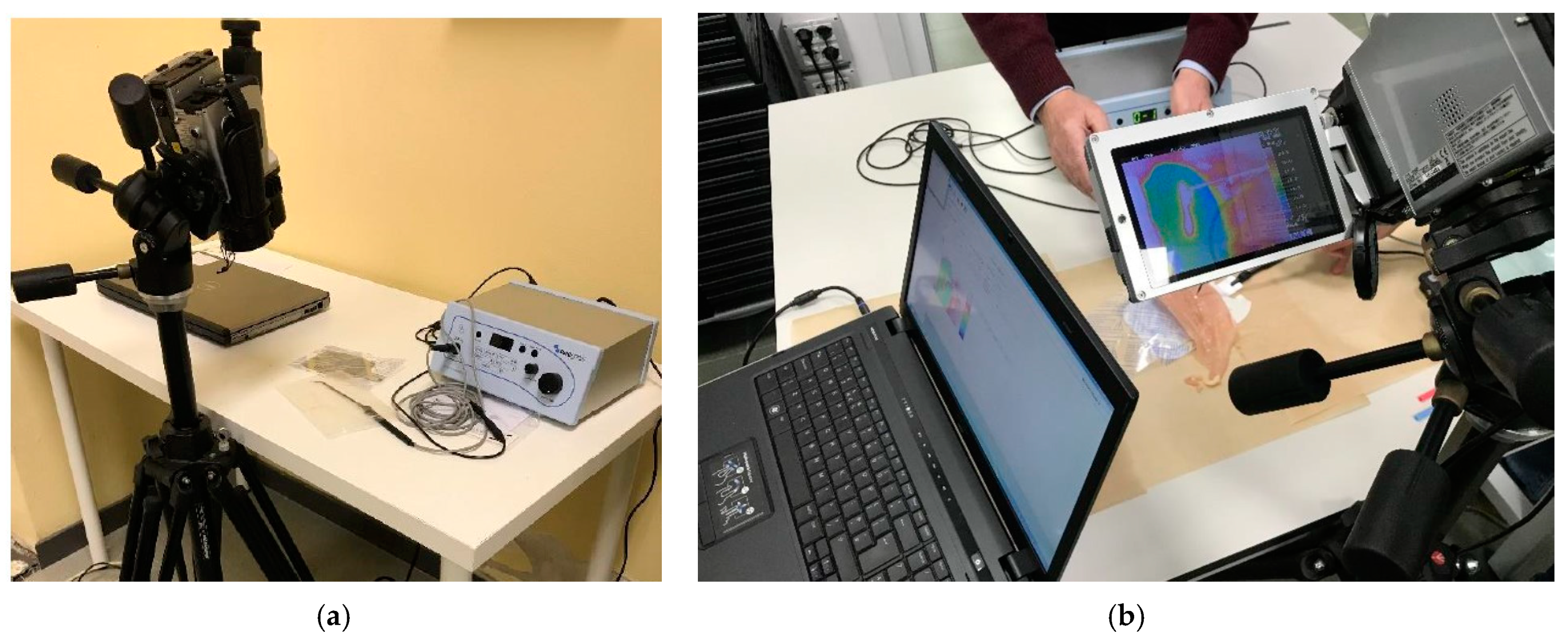
Thermographic measurements were carried out using a NEC H2640 thermal imager, (AVIO (NEC), Tokyo, Japan)setting the emissivity at ε = 0.45 and acquisition frequency at 1 Hz, with a temperature range of 0 ÷ 2000 °C, and image mode S16. Specifically, the emissivity was set based on a calibration procedure and a thermocouple. Figure 3a shows the experimental equipment, with the thermal camera on the left and the Oneyonis® device on the table, including the electrical cable and the probe. Figure 3b shows one moment of the experiment and the experimental setup that includes a laptop, thermal imaging equipment, an infrared camera mounted on a tripod, and the cold plasma device. The light dot, in the center of the photo, is the cold plasma generated by the probe while acting on organic (dead) tissue. The detected thermographic image can be observed through the camera display: it shows a thermal image with various colors representing different temperatures captured by the infrared camera.
2.5. Test Conditions and Procedures
The test parameters were set to be as in line as possible with clinical operating conditions, as well as to simulate severe use of the instrument.
Specifically, a dissipated electric power of 13 W was considered and a continuous operation period of 60 s. The temperature field was monitored throughout the experiment, as well as in the following 60 s after switching off, which represents the most interesting phase of the experiment. This extension not only allowed us to observe the cooling curve of the materials but also to perform a temperature analysis in the absence of plasma, which is useful for avoiding the risk of introducing systematic errors to the temperature readings. Measuring temperatures using thermography, in fact, can prove more difficult than expected in the presence of multiple materials, as in the present case.
Thermography is a technique used to detect temperature variations in objects or surfaces, including organic matter [21,22]. It works by detecting infrared radiation (IR) emitted by the object, which is related to its temperature. Every material has a typical emissivity (ε), which determines how efficiently it emits IR. It is a dimensionless parameter, as it simply represents the IR fraction emitted compared to that emitted by a black body at the same temperature (where zero represents total absorption and one represents total IR emission). Table 3 reports the representative emissivity for materials relevant to our study, showing how their values can largely vary from each other but also the notable variation that can occur within a single material under different conditions.
In addition, cold plasma is also present inside the thermal image. It is generated in air and its emissivity can vary widely depending on the specific environmental conditions under which the plasma emerges, including temperature, pressure, composition of gases involved, methods of plasma generation, and so on.
The direct measurement of plasma temperature is out of scope, assuming that the plasma is in thermal equilibrium with the steel. The temperature of the steel was detected when the probe was not submerged (and thus shadowed) in the plasma, or immediately after the power supply was discontinued and the plasma terminated.
3. Results and Discussion
3.1. Preliminary Test
A preliminary test was performed considering the following:
- a.
- The original probe electrode, without insulation.
- b.
- The surgeon’s typical method of device use.
- c.
- A deliberately wide acquisition thermal range to avoid the phenomena of saturation.
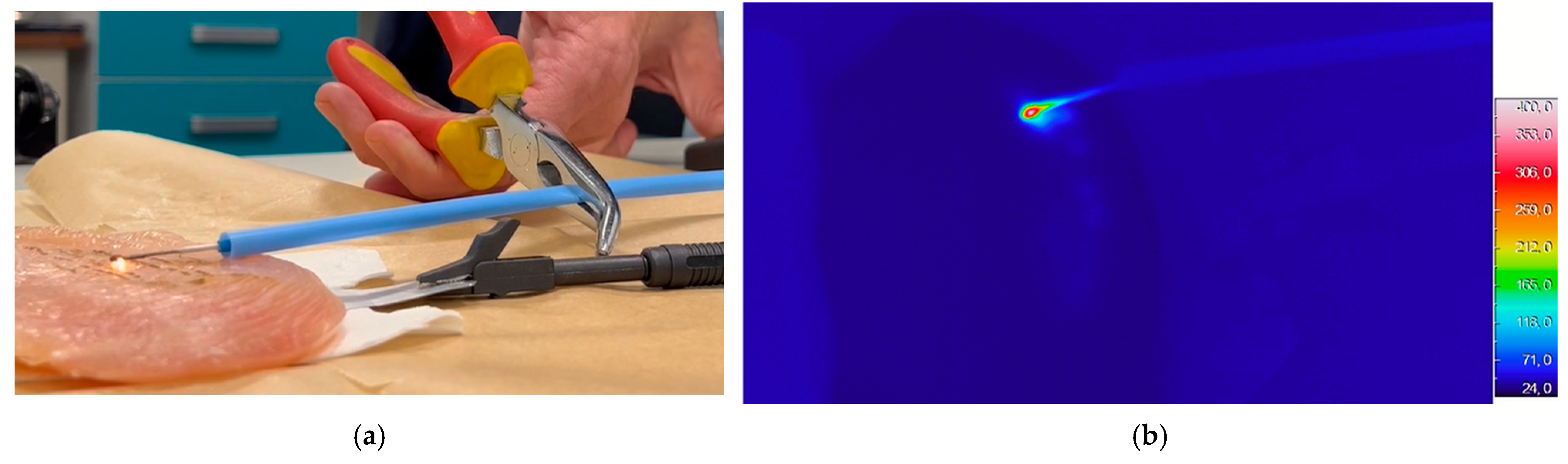
In Figure 4, images from the experiment are reported. Figure 4a displays the experimental apparatus, highlighting the cold plasma surgical tool in operation. It provides a clear view of the physical setup, including main instrumentation and the positioning of the probe relative to the tissue or material under testing. Electrode, plasma generated, and traces left on the tissue by their action are shown. The safety measures used during the experiment are also evident, such as pliers, the auxiliary insulation (in blue), and the earth connection. Figure 4b is the related thermographic image revealing the temperature distribution generated by cold plasma activation. Different colors indicate varying temperatures, with warmer areas likely representing the points of direct plasma interaction and cooler areas showing the insulated or less affected regions. This analysis is crucial for understanding the thermal impact of cold plasma technology, highlighting the effectiveness of insulation materials and the spatial distribution of heat around the probe. A concentration of temperature (i.e., hot-spot) located around the tip of the probe, immersed in the plasma, with a width of the order of four/five times its thickness (i.e., <5 mm) is quite evident, together with an immediate drop in temperatures both around this hot-spot and along the metal electrode. Thermal traces of the plasma on the tissue are also visible.
This first experiment permitted the following:
- Ensuring the correct functioning of the equipment.
- Observing the phenomenon of switching the plasma on and off.
- Gaining some experience with the methods of plasma intervention on tissues (identifying, for example, a method of translating the electrode).
- Measuring the expected maximum temperatures (T < 400 °C).
- Measuring the shape of the discharges in the absence of insulators.
- Verifying the thermal imaging camera’s ability to observe the phenomena.
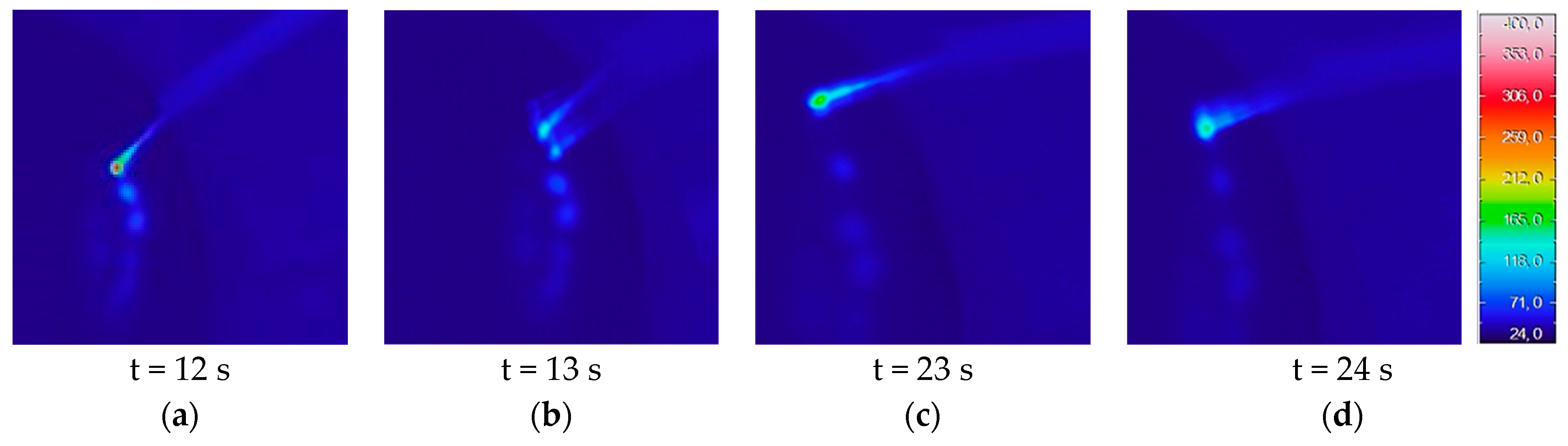
It emerges that how the temperatures fluctuate is based on whether the plasma is active or not (as shown in Figure 5). Despite this variability, due to the operational methods (e.g., probe usage technique) and substrate’s characteristics (e.g., mixture content), Tmax = 400 °C can be conveniently used.
The test also made the following evident:
- The temperature decreases rapidly with increasing distance from the plasma source; indeed, at a distance w << 10 mm it drops below 100 °C.
- The organic substrate remains at the initial temperature except closer to the plasma.
- The presence of an insulating material creates a discontinuity in terms of temperature readings, due also to the different emissivity of materials (as detailed below).
3.2. Preliminary Dimensioning
The preliminary test permitted a preliminary dimensioning of the insulation.
In terms of electrical insulation, for a material with an electric potential V ≤ 2.0 kV and a maximum electric field strength Emax = 17–33 V/μm, the required thickness (τ) to ensure insulation ranges from τ = 60 to 120 μm.
In terms of thermal insulation, with an expected Tmax = 400 °C and an acceptable surface temperature of 60 °C, a temperature difference of ΔT = 340 °C is yielded. Considering the alumina’s thermal conductivity (k = 30 w/(m·K), assuming the heat transfer equation in steady state, one-dimensional heat conduction, and ignoring radiation and convection losses, it is possible to quickly estimate a thickness of τ = 11 mm.
However, this value lacks real significance, as it represents the insulation required to maintain a cable stable at high temperatures throughout. First, radiation and convection phenomena cannot be ignored. Furthermore, as emerged from tests, only the cable end, submerged in the plasma, reaches Tmax, with other temperatures rapidly decreasing. These circumstances force the adoption of more refined models (as discussed below) and the use of experimental information only at this stage.
For instance, despite Tmax not permitting a quick estimation of the insulation thickness, it nonetheless confirmed Al2O3’s suitability and ruled out the possibility of using the existing Teflon film, considering its operating temperatures <210 ÷ 260 °C.
The test also enabled the determination of the width (w) of the area requiring thermal and electrical isolation. This was identified as being w ~ 5 mm from the probe’s end.
In summary, this initial analysis identified a potential insulation solution in the use of an Al2O3 layer with a thickness τ ~ 120 μm and a width w ~ 5 mm.
3.3. Ultra-Thin Coating (1 μm of Al2O3)
The next test considered a probe with a 1 μm Al2O3 coating and results are displayed in Figure 6. The range for capturing data with the thermal camera was narrowed to 0–500 °C to enhance detail. Even though the insulation thickness is much lower than initial estimates suggested, the experiment returned several useful results.
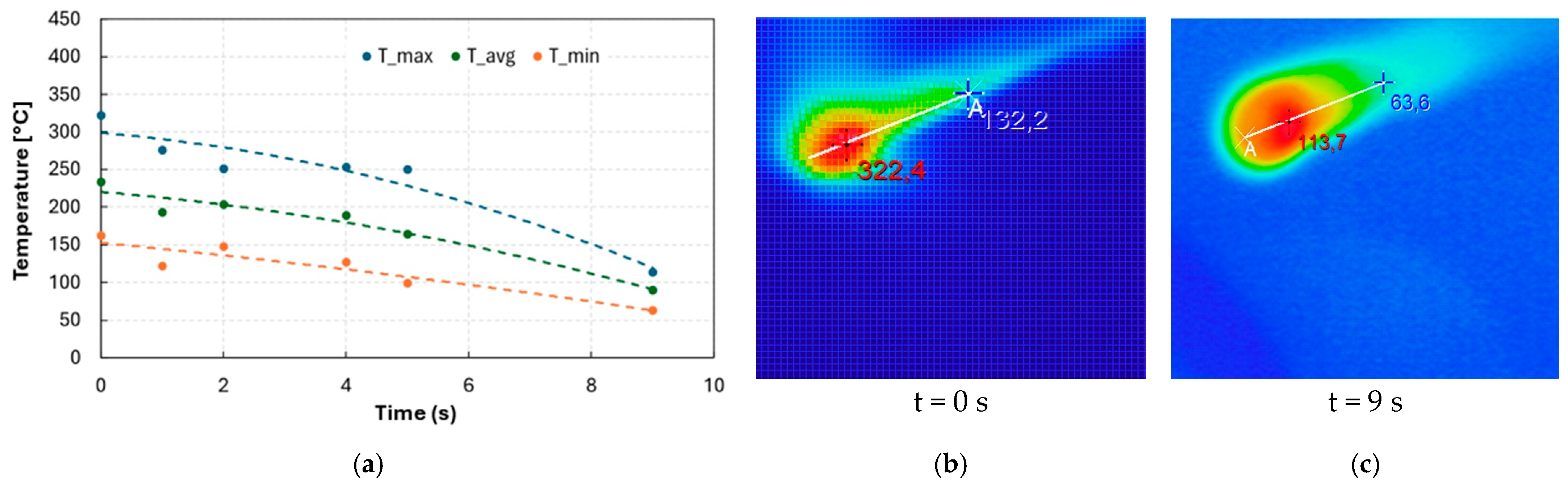
Figure 6a presents temperatures in terms of their maximum (Tmax), average (Tavg), and minimum (Tmax). To avoid the local effects and reduce measurement errors, the temperature is evaluated along a segment of length equal to the width of the electrode.
Accordingly, it can be argued that Tavg represents the most representative factor to describe the phenomenon. However, to be conservative, the analysis was based on Tmax. The results show Tmax = 322 °C when the plasma is turned off, quickly decreasing to drop below 100 °C in about 10 s.
Figure 6b,c display snapshots at the moments when the plasma is deactivated and after 9 s of cooling, respectively.
3.4. Insulating Tube (400 μm Al2O3)
The test continued with the scope of evaluating the effect of thermal insultation offered by a commercial alumina insert, i.e., a capillary Degussit F121-11200-10360 (Kyocera production, Kyoto, Japan, distributor Italbras). This material, with an operational temperature Toper = 1290 °C and Emax = 20 ÷ 30 kV/μm, was considered able to fulfill the requirements. A 20.0 mm wide capillary was used, with a 400 μm thick insulation layer of Al2O3, predicted to provide adequate insulation.
Results are presented in Figure 7, showing a Tmax = 259 °C (Figure 7b) at shutdown, which then decreased to below 100 °C in 3–4 s, and further reduced to 70 °C after 5 s. (Figure 7c).
Earlier findings are the following:
- -
- Tmax at shutdown is evidently reduced by the insulation thickness: 322 vs. 259 °C (−20%) passing from 1 to 400 μm;
- -
- The same variability in temperature measurements is reduced;
- -
- The cooling of the steel part is much faster: e.g., Tmax = 75 °C after 4 s, compared to approx. 190 °C in the case without insulation;
- -
- The insulation tends to cool much more slowly than the metal and redistribute the heat, resulting in it being uniformly hot (Figure 7c).
In short, although the insulation acts to reduce surface temperatures, it also spreads the heating to areas of the probe that were not previously affected by the phenomenon. Both aspects must be appropriately considered.
3.5. Insulating Rings (600 μm Al2O3)
The test was reiterated considering, instead of a single capillary, a series of six adjacent Al2O3 rings, each one 3.2 mm wide, resulting in a total insert width of 19.2 mm. They introduced a 600 μm insulation layer of Al2O3.
Results are displayed in Figure 8. Due to the better insulation, Tmax moves from 639 °C (uncoated) and 322 °C (coated) to 257 °C. Moreover, during the cooling phase, it went down to 150 °C (−41%) after just 2 s (Figure 8b,c).
Further findings are the following:
- -
- Tmax at shutdown is not significantly reduced by insulation thickness increases: 259 vs. 257 °C (−0.7%) passing from 400 to 600 μm (+50%).
- -
- There is a comparable cooling speed on the probe’s end too (97 vs. 111 in 2 s).
In short, it is incorrect to assume that thicker insulation always results in better performance. Beyond certain thicknesses, the benefits of increased insulation become negligible and may not justify the potential drawbacks.
3.6. Temperature on the Surface
In thermography, material emissivity significantly impacts temperature readings. In the provided thermal image, a temperature measurement was taken with an emissivity value of εsteel = 0.45, which is typical for polished steel. This value, as said, was derived by a calibration procedure carried out using a thermocouple.
Based on this assumption, the measured highest temperature of alumina appears to be ~150 °C (423 K), yet this value significantly exceeds the actual temperature. It is possible to estimate the correct value considering the Al2O3 emissivity, εalumina = 0.8. The Stefan–Boltzmann law for non-blackbody materials can then be used, which allows us to equate the radiant power per unit area for both materials at their respective emissivities and temperatures, as follows:
with temperatures in K, and Talumina = 93 °C (366 K). This value represents the theoretical temperature one would measure if the alumina had an emissivity of 0.8 and emitted the same amount of radiant energy as the steel did at 150 °C with an emissivity of 0.45. Although this is just a simplified model, it can provide a useful estimation.
3.7. Electric Insulation
The previous tests also aimed to evaluate the insulation considering an electrical potential of 2 kV. In scenarios involving ultra-thin coatings, frequent discharges were noted from the electrode, suggesting that the coating’s thickness was insufficient for adequate insulation (Figure 9a). Conversely, with thicker insulation layers, lateral discharges were still observed during testing but were notably less frequent (Figure 9b). Furthermore, it became apparent that these discharges emanated from areas of the electrode not covered by the insulation, rather than from an insufficient coating thickness.
To verify this observation, the test with the insulation tube considered minor geometric changes to minimize the exposed part. Operationally, this involved machining the terminal part of the probe, removing the Teflon film, and inserting the capillary tube so that the probe now protruded less than 0.5 mm from the ceramic tube. All lateral discharges ceased, confirming it as the most effective technical solution to the issue (Figure 9c).
Specifically, the following are noted:
- Figure 9a illustrates the initial challenge encountered with our probe design, where plasma discharges occur in an irregular and uncontrolled manner, predominantly lateral to the electrode tip. This pattern of discharge is undesirable for precise surgical applications, as it can lead to unintended damage to surrounding tissues. In surgical practice, the precision of plasma application is critical; the surgeon relies on the predictability and focus of the plasma emanating from the probe’s tip to target specific tissue areas without affecting adjacent healthy tissues.
- Figure 9b demonstrates an improvement in controlling the plasma discharge, with a reduction in the lateral spread of plasma along the length of the electrode. However, despite the lessened intensity and more concentrated plasma compared to Figure 9a, the discharges remain partially lateral, indicating that while the control over plasma generation has improved, it still does not fully meet the ideal criteria for surgical precision. The persistence of lateral plasma formation, even if less intense, underscores the need for further refinement in probe design to focus the plasma discharge exclusively at the tip.
- Figure 9c showcases the optimal outcome achieved through modifications to the probe design, resulting in a focused, intense plasma discharge precisely at the tip of the probe. This configuration aligns with the surgical necessity for a concentrated hot-spot at the tip, enabling the surgeon to perform highly precise procedures without the risk of damaging unaffected tissues. The intense and centralized plasma generation seen in Figure 9c represents a significant advancement, ensuring that the plasma’s therapeutic and cutting effects are confined to the desired surgical site.
The progression from Figure 9a through 9c highlights the iterative design improvements made to address the challenge of lateral plasma discharges. By focusing on enhancing the precision and control of plasma generation, we have developed a probe that significantly mitigates the risk of unintended tissue damage, thereby improving surgical outcomes.
3.8. Surface Effects
While not the primary objective, applying a ceramic coating can also safeguard the electrode, enhancing its performance and durability. Figure 10 displays the probes’ condition post-experiment, showing that the surfaces coated with alumina are exceptionally well-preserved.
With respect to the aggressiveness of the organic material, as visible in Figure 10a, even an ultra-thin coating (such as 1 μm) can predictably offer intial protection thanks to the alumina’s capability to shield the underlying metal from corrosive biological fluids and mechanical wear. More robust protection (as shown in Figure 10a,b) not only improves the electrode functionality, durability, and operational efficiency but also maintains a safer operating temperature, contributing to safer surgical environments.
3.9. System Modelling
A numerical approach enhances the understanding of experimental outcomes. Based on finite elements analysis (FE) and the Ansys Workbench toolkit (2023 R1), the three geometries of the probe were considered (i.e., with coating, tubes, and rings, as in Figure 11). They were discretized using hexagonal elements, each with eight nodes, for an overall mesh comprised approx. 56,000 nodes and 16,000 elements, depending on the specific case.
These numerical models simplified the physical reality to some extent. At first, it was assumed that all elements were in direct contact, facilitating heat transfer by conduction. The assumption overlooks the insulating effect that air gaps would provide, such as those between the cable and the ceramic inserts or among the inserts themselves. The long cable has been eliminated, replaced by a section of it with the addition of boundary conditions, designed to ensure heat absorption along the cable.
Each numerical analysis was conducted by two subsequent steps as follows:
- A steady-state thermal (SST) analysis, evaluating the thermal equilibrium of a system under activated plasma conditions. The SST analysis followed a simplified model validated in [8], which was applied in a comparable scenario involving cold plasma generation electrodes. It utilized a Temperature Boundary Condition (TBC) corresponding here to the Tmax values at t = 0 s as observed by experiments (as detailed in Table 4), and this condition was applied to the top of the probe. An additional TBC was set as Tmin at t = 22 °C to the opposite end, reflecting heat absorption assured by the (3 m) long steel cable. At equilibrium, the heat is distributed along the probe by conduction, and temperatures consider the heat exchange by convection with the surrounding air. Radiation can be neglected. In this scenario, the ambient temperature was Tenv = 17 °C, which also denoted the air temperature that affects convective heat transfer. The convective heat transfer coefficient was set to h = 30 W/m2 °C. This value is not significantly altered by the specific material, as it primarily depends on the surrounding air conditions and the temperature differential between the steel surface and the ambient air, rather than on the material’s intrinsic properties. The thermal conductivity was aligned to the properties of each material involved (k = 50, 30, and 0.25 W/m °C for steel, alumina, and Teflon, respectively [8,17,18,19]).
- A transient thermal (TT) analysis, evaluating the system cooling. It was performed starting with the mentioned steady-state thermal condition and permitted to follow the thermal evolution during cooling phases caused by convection. External conditions are the same as in the SST analysis (i.e., Tenv, h, …). Radiation was also neglected.
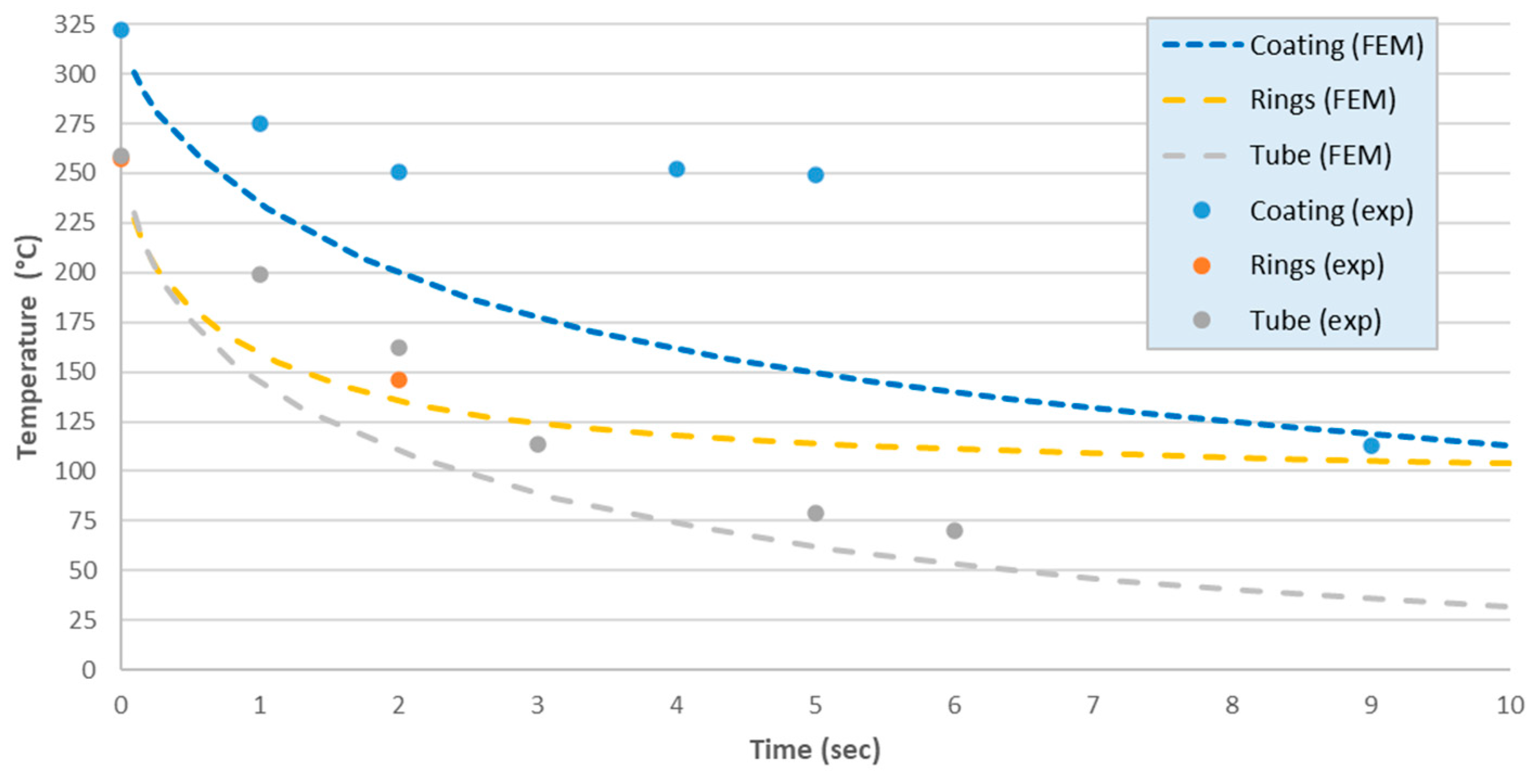
Figure 12 and Table 4 compare experiments and simulations in terms of Tmax. The data and their graphical representation clearly show how design modifications have impacted the probe’s ability to dissipate heat. Notably, the progression towards more advanced designs correlates with a faster return to baseline temperatures, underscoring the effectiveness of these design improvements in enhancing thermal management.
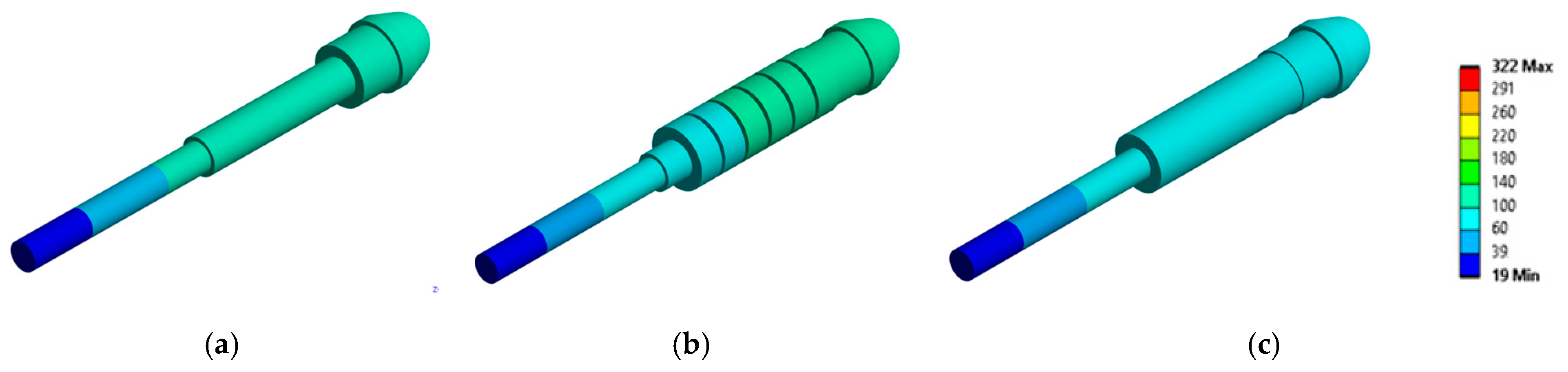
Figure 13 and Figure 14 show the outputs of SST and TT analyses, reporting the simulated thermal states when the plasma is turned off and after 10 s of cooling, respectively, for the three different probe configurations.
All images use the same color scale for immediate comparison, with the color scheme chosen to enhance interpretability: shades of green distinctly mark the regions where Teflon can be applied as supplementary insulation without surpassing its thermal tolerance limits. Similarly, light blue areas delineate zones that are unlikely to cause substantial tissue damage if the probe momentarily comes into direct contact with them.
Comparing individual imagines both for SST and TT analyses, there is a clear trend towards improved thermal focus and precision with respect to the three design solutions. This progression illustrates the effectiveness of design modifications in enhancing the probe’s ability to localize heat at the tip, which is critical for surgical accuracy and safety. The comparison suggests enhancements in how the probe dissipates heat away from non-target areas. The advanced design represented in Figure 13c and Figure 14c likely incorporates materials or structural changes that facilitate rapid heat dissipation, reducing thermal exposure to surrounding tissues.
3.10. Final Considerations
Several findings also emerge as follows:
- -
- The most effective insulation is not merely determined by its thickness; while a thicker layer can lower the maximum temperatures, it may also impede the system’s ability to cool down swiftly.
- -
- A proper balance between insulation thickness and operational efficiency has to be underscored, revealing that beyond a certain threshold, increased thickness may have diminishing returns.
- -
- Coatings with thicknesses in the micron range do not significantly influence the thermal profile of the electrode and their use may only create complications with respect to other aspects (e.g., electrical insulation, chemical resistance, biocompatibility, etc.)
- -
- Teflon, which is already present to protect the electrical cable, is an excellent insulation. However, it cannot be placed in direct contact with the probe’s functional part that is immersed in the plasma, as this would cause the Teflon to melt. Therefore, insulating (ceramic) inserts are required, even for distances smaller than those considered in the present context.
4. Conclusions
The potential of air plasma technology in reducing post-operative pain, accelerating wound healing, and achieving better functional and aesthetic outcomes is well-recognized, underscoring its significant role in modern surgical practices. At the same time, engineering limitations currently hinder its broader application. This study contributes to this advancement by offering a detailed thermal analysis under varying conditions and designs of surgical tools, recognizing that the following:
- Through general considerations and testing related to thermal and electrical insulation, alumina (Al2O3) emerged as the optimal material for protection of surgical electrodes used in low-temperature cold plasma surgery.
- With a high dielectric strength ranging between 17 and 33 V/μm, alumina significantly enhances the electrical insulation of surgical electrodes even with respect to thin coatings. This improvement is pivotal in preventing unintended electrical discharges during surgery, thus contributing to safer surgical outcomes.
- Alumina, at greater thicknesses, is also effective in managing thermal conductivity, ensuring that the temperature of the surgical tools did not exceed safe operational limits. Specifically, the material’s ability to maintain tool temperatures below 60 °C during operations minimizes tissue damage and promotes better healing, as compared to traditional electrocautery tools that can exceed temperatures of 100 °C.
- Alumina, also known for its corrosion and wear resistance, offers an added advantage in terms of durability and compatibility of surgical tools. The experiments showed the protective effect of Al2O3 coatings against degradation, accumulation of organic substances, and so on, making new tools suitable for prolonged surgical operation.
In conclusion, the present study underlines the critical role of material design, specifically Al2O3–based coatings, in advancing low-temperature plasma surgical tools. The findings support the broader adoption of this technology in surgical applications, paving the way for more effective, safe, and patient-friendly surgical procedures. Moreover, the implications of this study extend beyond surgical tool design, suggesting a framework for the future exploration of materials that can withstand the harsh conditions of medical applications.
Author Contributions
Conceptualization, C.F. and M.A.; methodology, V.M., C.F. and G.P.; software, A.P. and M.A.; validation, A.P. and M.A.; formal analysis, G.P.; investigation, V.M., C.F. and G.P.; resources, M.A and A.P.; data curation, C.F.; writing—original draft preparation, V.M., G.P. and C.F.; writing—review and editing, C.F.; visualization, M.A.; supervision, C.F.; project administration, M.A.; funding acquisition, C.F. and M.A. All authors have read and agreed to the published version of the manuscript.
Funding
This study is part of the “AirplasmaEVO” project (CUP I33D22000500005), an action aimed at the advancement of cold plasma medical technology, with the aim of developing new devices for precision surgery in both the human and veterinary fields. This research was supported by the Meditech Mediterranean Competence Center for Innovation through the “Meditech Call No. 2-2021”.
Institutional Review Board Statement
Not applicable (the study did not involve humans or living animals).
Informed Consent Statement
Not applicable.
Data Availability Statement
Experimental data will be provided on request.
Acknowledgments
Authors thank Carmine Pappalettere and Katia Casavola for their suggestions and supervision during research implementation, and Antonella Rizzo of ENEA—Brindisi for her support in carrying out the alumina coatings. The authors wish to acknowledge the use of an artificial intelligence-based language enhancement tool for reviewing and improving the language quality of this manuscript.
Conflicts of Interest
The authors declare no conflicts of interest.
References
- Ellis, H.; Sala, A. A History of Surgery; CRC Press: Boca Raton, FL, USA, 2018. [Google Scholar]
- Metelmann, H.R.; von Woedtke, T.; Weltmann, K.D.; Emmert, S. Textbook of Good Clinical Practice in Cold Plasma Therapy; Springer: Berlin, Germany, 2022. [Google Scholar]
- Lipscomb, G.H.; Givens, V.M. Preventing Electrosurgical Energy-Related Injuries. Obstet. Gynecol. Clin. N. Am. 2010, 37, 369–377. [Google Scholar] [CrossRef] [PubMed]
- Vilos, G.A.; McCulloch, S.; Borg, P.; Zheng, W.; Denstedt, J.D. Intended and Stray Radiofrequency Electrical Currents During Resectoscopic Surgery. J. Am. Assoc. Gynecol. Laparosc. 2000, 7, 55–63. [Google Scholar] [CrossRef] [PubMed]
- Odell, R.C. Surgical Complications Specific to Monopolar Electrosurgical Energy: Engineering Changes That Have Made Electrosurgery Safer. J. Minim. Invasive Gynecol. 2013, 20, 288–298. [Google Scholar] [CrossRef] [PubMed]
- Tixier, F.; Garc¸on, M.; Rochefort, F.; Corvaisier, S. Insulation failure in electrosurgery instrumentation: A prospective evaluation. Surg. Endosc. 2016, 30, 4995–5001. [Google Scholar] [CrossRef] [PubMed]
- Spaner, S.J.; Warnock, G.L. A brief history of endoscopy, laparoscopy, and laparoscopic surgery. J. Laparoendosc. Adv. Surg. Tech. 1997, 7, 369–373. [Google Scholar] [CrossRef] [PubMed]
- Fragassa, C.; Arru, M.; Capelli, F.; Pavlovic, A.; Gherardi, M. Measuring Temperatures Generated by Air Plasma Technology. Power Eng. Eng. Thermophys. 2022, 1, 76–91. [Google Scholar] [CrossRef]
- Giorgianni, B. Post-Market Surveillance in the Italian Medical Device Market: Analysis of Company Tools and Approaches. Master’s Thesis, Politecnico di Milano, Milan, Italy, 18 July 2023. [Google Scholar]
- AirPlasma® Technology. OTECH Industry. Available online: https://otechindustry.it/images/otechindustry/pdf/otech_industry_airplasma_technology_plasma_air.pdf (accessed on 15 March 2024).
- Bannino, A. Electrosurgical Apparatus to Perform a Tissue Cut on the Body of a Human or Animal Patient. U.S. Patent No. 11,191,585, 7 December 2021. [Google Scholar]
- Lacitignola, L.; Desantis, S.; Izzo, G.; Staffieri, F.; Rossi, R.; Resta, L.; Crovace, A. (Comparative morphological effects of cold-blade, electrosurgical, and plasma scalpels on dog skin. Vet. Sci. 2020, 7, 8. [Google Scholar] [CrossRef] [PubMed]
- Tamburro, R.; Brunetti, B.; Muscatello, L.V.; Mantovani, C.; De Lorenzi, D. Short-term surgical outcomes and histomorphological evaluation of thermal injury following palatoplasty performed with diode laser or air plasma device in dogs with brachycephalic airway obstructive syndrome. Vet. J. 2019, 253, 105391. [Google Scholar] [CrossRef] [PubMed]
- Berger, L. Dielectric strength of insulating materials. Carbon 2006, 1, 2. [Google Scholar]
- Gnonhoue, O.G.; Velazquez-Salazar, A.; David, É.; Preda, I. Review of technologies and materials used in high-voltage film capacitors. Polymers 2021, 13, 766. [Google Scholar] [CrossRef] [PubMed]
- Davis, K. Material Review: Alumina (Al2O3). Sch. Dr. Stud. Eur. Union J. 2010, 2, 1–109. [Google Scholar]
- Touzin, M.; Goeuriot, D.; Guerret-Piecourt, C.; Juvé, D.; Fitting, H.J. Alumina based ceramics for high-voltage insulation. J. Eur. Ceram. Soc. 2010, 30, 805–817. [Google Scholar] [CrossRef]
- Abyzov, A.M. Aluminum oxide and alumina ceramics (review). Part 1. Properties of Al2O3 and commercial production of dispersed Al2O3. Refract. Ind. Ceram. 2019, 60, 24–32. [Google Scholar] [CrossRef]
- Final Advanced Materials. DataSheet: Sintered Technical Ceramics (Ref. 1MG.002). Available online: https://www.final-materials.com/gb/index.php?controller=attachment&id_attachment=20 (accessed on 15 March 2024).
- Grilli, M.L.; Valerini, D.; Rizzo, A.; Yilmaz, M.; Song, C.; Hu, G.; Mikhaylov, A.; Chierchia, R.; Rinaldi, A. A comparative study of the mechanical and tribological Properties of thin Al2O3 coatings fabricated by atomic layer deposition and radio frequency sputtering. Phys. Status Solidi (A) 2022, 219, 2100398. [Google Scholar] [CrossRef]
- Speakman, J.R.; Ward, S. Infrared thermography: Principles and applications. Zool. Jena 1998, 101, 224–232. [Google Scholar]
- Lahiri, B.B.; Bagavathiappan, S.; Jayakumar, T.; Philip, J. Medical applications of infrared thermography: A review. Infrared Phys. Technol. 2021, 55, 221–235. [Google Scholar] [CrossRef] [PubMed]
- Quinn, B.M. Thermal Radiative Transfer and Properties; John Wiley & Sons: Hoboken, NJ, USA, 1992; p. 56. ISBN 9780471539827. [Google Scholar]
- Ashrae, A.H. Handbook: Fundamentals—IP Edition; American Society of Heating, Refrigerating and Air-Conditioning Engineers: Atlanta, GA, USA, 2009. [Google Scholar]
Figure 1.
Cold plasma technology showcased in surgical applications: (a) Oneyonis® device and scalpel (courtesy of Otech Industries Srl); (b) surgical probe for endoscopy, comprising a functional terminal part, steel-made electrical cable, and a high-voltage connector; (c) probe details.
Figure 1.
Cold plasma technology showcased in surgical applications: (a) Oneyonis® device and scalpel (courtesy of Otech Industries Srl); (b) surgical probe for endoscopy, comprising a functional terminal part, steel-made electrical cable, and a high-voltage connector; (c) probe details.

Figure 2.
Alternative insulation solutions by Al2O3: (a) coating; (b) flexible tape; (c) tubes; (d) rings.
Figure 2.
Alternative insulation solutions by Al2O3: (a) coating; (b) flexible tape; (c) tubes; (d) rings.

Figure 3.
Thermographic measurements: (a) test equipment with a thermal camera and cold plasma surgery equipment; (b) a moment of the experiment, showing the detected thermographic image.
Figure 3.
Thermographic measurements: (a) test equipment with a thermal camera and cold plasma surgery equipment; (b) a moment of the experiment, showing the detected thermographic image.

Figure 4.
Images from the experiment (at s = 30 s): (a) experimental setup showcasing the probe and the cold plasma generation equipment; (b) corresponding thermographic image capturing the thermal distribution during plasma activation, illustrating areas of temperature variance.
Figure 4.
Images from the experiment (at s = 30 s): (a) experimental setup showcasing the probe and the cold plasma generation equipment; (b) corresponding thermographic image capturing the thermal distribution during plasma activation, illustrating areas of temperature variance.

Figure 5.
Thermographic images showcasing temperature fluctuations at various stages of the experiment, with Tmax reaching approx.: (a) 380 °C during plasma activation; (b) 120 °C shortly after deactivation; (c) 160 °C during a subsequent phase; and (d) 140 °C at a later moment.
Figure 5.
Thermographic images showcasing temperature fluctuations at various stages of the experiment, with Tmax reaching approx.: (a) 380 °C during plasma activation; (b) 120 °C shortly after deactivation; (c) 160 °C during a subsequent phase; and (d) 140 °C at a later moment.

Figure 6.
Probe temperature and cooling in the case of τ = 1 μm Al2O3 insulation: (a) trend of temperatures; (b) plasma deactivation at t = 0 s; (c) t = 9 s.
Figure 6.
Probe temperature and cooling in the case of τ = 1 μm Al2O3 insulation: (a) trend of temperatures; (b) plasma deactivation at t = 0 s; (c) t = 9 s.

Figure 7.
Probe temperature and cooling in the case of τ = 400 μm Al2O3 insulation: (a) trend of temperatures; (b) plasma deactivation at t = 0 s; (c) t = 5 s.
Figure 7.
Probe temperature and cooling in the case of τ = 400 μm Al2O3 insulation: (a) trend of temperatures; (b) plasma deactivation at t = 0 s; (c) t = 5 s.

Figure 8.
Probe temperature and cooling in the case of τ = 600 μm Al2O3 insulation: (a) trend of temperatures; (b) plasma deactivation at t = 0 s; (c) t = 2 s.
Figure 8.
Probe temperature and cooling in the case of τ = 600 μm Al2O3 insulation: (a) trend of temperatures; (b) plasma deactivation at t = 0 s; (c) t = 2 s.

Figure 9.
Observations on electrical insulation: (a) 1 μm does not contrast lateral discharges (with anomalous generation of plasma); (b) 600 μm prevents lateral discharges where the electrode is completely protected; (c) 400 μm is a proper solution when changes in geometry are provided.
Figure 9.
Observations on electrical insulation: (a) 1 μm does not contrast lateral discharges (with anomalous generation of plasma); (b) 600 μm prevents lateral discharges where the electrode is completely protected; (c) 400 μm is a proper solution when changes in geometry are provided.

Figure 10.
Probes’ condition at the end of the experiments with respect to different insulations: (a) without coating; (b) with rings (600 μm); (c) with a tube (400 μm) and design changes.
Figure 10.
Probes’ condition at the end of the experiments with respect to different insulations: (a) without coating; (b) with rings (600 μm); (c) with a tube (400 μm) and design changes.

Figure 11.
Systems under FE discretization, i.e., the probe with: (a) 1 μm coating; (b) rings (600 μm); (c) tube (400 μm).
Figure 11.
Systems under FE discretization, i.e., the probe with: (a) 1 μm coating; (b) rings (600 μm); (c) tube (400 μm).

Figure 12.
Systems’ cooling: experiment vs. simulation.

Figure 13.
Steady-state thermal (SST) analysis reporting the thermal state when the plasma is turned off in the case of the probe: (a) with coating (1 μm); (b) with rings (600 μm); (c) with tube (400 μm).
Figure 13.
Steady-state thermal (SST) analysis reporting the thermal state when the plasma is turned off in the case of the probe: (a) with coating (1 μm); (b) with rings (600 μm); (c) with tube (400 μm).

Figure 14.
Transient thermal (TT) analysis reporting the thermal state after t = 10 s in the case of the probe: (a) with coating (1 μm); (b) with rings (600 μm); (c) with tube (400 μm).
Figure 14.
Transient thermal (TT) analysis reporting the thermal state after t = 10 s in the case of the probe: (a) with coating (1 μm); (b) with rings (600 μm); (c) with tube (400 μm).


| Material | Emax | Material | Emax | Material | Emax |
|---|---|---|---|---|---|
| Air (at 1 bar) | 3 | Glass | 9.8 ÷ 13.8 | PTFE (extruded) | 20 |
| Perfect vacuum | 1012 | Not | 118 | PTFE (film) | 60 ÷ 173 |
| Alumina (Al2O3) | 17 ÷ 33 | Polyethylene | 19 ÷ 160 | PZT (Pb(Ti,Zr)O₃) | 10 ÷ 25 |
| Bakelite | 10 | Polystyrene | 19.7 | Quartz glass (SiO2) | 470 ÷ 670 |
| Ba-Sr. Titanates | 5 | Pyrex (Borosilicate glass) | 20 ÷ 40 | Titanium oxide (TiO2) | 5 |
| Diamond | 2000 | Porcelain | 12 ÷ 30 |
| Physical Properties | Mechanical Properties | Temperature/Electrical | |||
|---|---|---|---|---|---|
| DIN ISO | C799 | Hardness (HV10) | >17,000 MPa | Operating temp. | <1700 °C |
| Al2O3 | 99.7% | Compressive strength | 2500 MPa | Thermal conductivity | 30 w/(m·K) |
| Density | 3.9 g/cm3 | Flexural strength | >370 MPa | Expansion coeff. | 10−6/K−1 |
| Open porosity | 0% | Elastic modulus | >380 GPa | El. resistivity (20 °C) | 1012 Ω·m |
| Toughness | 4 MPa·m1/2 | (600 °C) | 1016 Ω·m | ||
| Dielectric strength | 17 kV/mm | ||||
| Material | ε |
|---|---|
| Steel (general) | 0.70–0.90 |
| Steel (polished) | 0.42–0.56 |
| Alumina | 0.70–0.90 |
| Teflon | 0.95–0.97 |
| Organic tissue | 0.98–0.99 |
Table 4.
Tmax values according to prediction and experiments (with respect to the last measured times).
Table 4.
Tmax values according to prediction and experiments (with respect to the last measured times).
| Case | Time (s) | Tmax (°C) | Time (s) | (°C) | err (%) | |
|---|---|---|---|---|---|---|
| Coating | 0 | 322 | 9 | 113 | 126 | 12 |
| Tube | 0 | 257 | 2 | 146 | 137 | −6 |
| Ring | 0 | 260 | 6 | 70 | 54 | −23 |
Disclaimer/Publisher’s Note: The statements, opinions and data contained in all publications are solely those of the individual author(s) and contributor(s) and not of MDPI and/or the editor(s). MDPI and/or the editor(s) disclaim responsibility for any injury to people or property resulting from any ideas, methods, instructions or products referred to in the content. |
© 2024 by the authors. Licensee MDPI, Basel, Switzerland. This article is an open access article distributed under the terms and conditions of the Creative Commons Attribution (CC BY) license (https://creativecommons.org/licenses/by/4.0/).
Share and Cite
MDPI and ACS Style
Fragassa, C.; Pappalettera, G.; Moramarco, V.; Pavlovic, A.; Arru, M. Enhancing Surgical Tool Performance with Alumina-Based Coatings: An Engineering Analysis. Sci 2024, 6, 24. https://doi.org/10.3390/sci6020024
AMA Style
Fragassa C, Pappalettera G, Moramarco V, Pavlovic A, Arru M. Enhancing Surgical Tool Performance with Alumina-Based Coatings: An Engineering Analysis. Sci. 2024; 6(2):24. https://doi.org/10.3390/sci6020024
Chicago/Turabian StyleFragassa, Cristiano, Giovanni Pappalettera, Vincenzo Moramarco, Ana Pavlovic, and Marco Arru. 2024. "Enhancing Surgical Tool Performance with Alumina-Based Coatings: An Engineering Analysis" Sci 6, no. 2: 24. https://doi.org/10.3390/sci6020024