Review

The Aero-Thermal Performance of Purge Flow and Discrete Holes Film Cooling of Rotor Blade Platform in Modern High Pressure Gas Turbines: A Review

1
Dipartimento di Ingegneria e Scienze Applicate, Università degli Studi di Bergamo, Viale Marconi 5, 24044 Dalmine, Italy
2
Department of Mechanics and Maritime Sciences, Division of Vehicle Engineering and Autonomous Systems, Chalmers University of Technology, SE-412 96 Gothenburg, Sweden
*
Author to whom correspondence should be addressed.
Int. J. Turbomach. Propuls. Power 2022, 7(3), 22; https://doi.org/10.3390/ijtpp7030022
Submission received: 22 February 2022 / Revised: 21 June 2022 / Accepted: 29 June 2022 / Published: 4 July 2022

Abstract

:
Design of cooling systems for rotor platforms is critical due to the complex flow field and heat transfer phenomena related to the secondary flow structures originating at the blade leading edge. Horseshoe vortex and passage vortex are the fluid-dynamic features that largely influence the aerodynamic behaviour and the thermal protection level of the platform. The driving parameter is the coolant to mainstream momentum flux ratio, but several issues have to be considered in the design process of cooling technologies. As well acknowledged, an in-depth understanding of losses and heat transfer phenomena are deemed necessary to design effective cooling systems. In the present review, measurements and predictions on the behaviour of the HPT rotor cooled platform, obtained during the last two decades by several research groups, are gathered, described and analysed in terms of aerodynamic losses and heat transfer performance, and are compared with one another with respect to the effectiveness level that is ensured.

1. Introduction

In modern high-pressure gas turbines, increased turbine inlet temperature values are required to implement an effective cooling design, so as to avoid metal damage and related operating failures. With the increase of turbine inlet temperature, the rotor platform becomes a critical region from the thermal protection point of view. Traditionally, film cooling technologies are implemented as a coolant fluid ensuing from a slot or discrete holes with the purpose of protecting the platform surface from excessive thermal load occurring (being exposed to gases ensuing from the combustor). Most of the available results presented in the open literature are about the thermal protection capability of cooling schemes operating on nozzle vane cascade. Much less attention has been devoted to the rotor blade platform thermal protection over the years, for at least three reasons. First, the general platform coolant to secondary flow interaction derived from nozzle vane cascade testing was expected to be replicated in the rotor blade cascade, assuming the rotation induced effect of second order relevance. Second, pieces of information could be derived from secondary air system studies, mostly focused on the sealing capability of purge flow issued from the stator to rotor interface gap [1,2,3,4]. Third, only a limited number of dedicated rotating facilities are available worldwide for testing the rotor blade platform, as also highlighted in [5], where the decrease of film cooling effectiveness, due to an increased rotational speed, was shown and explained by the wakes originating from the stator trailing edge. Severe mixing was therein highlighted due to major unsteady turbulent wake effects. Simulating rotation effects on stationary linear cascades was perceived as unsuitable to fully reproduce the complex flow field entering the rotor; see, for example [6], which is among the few works available in the open literature, presenting measurements on the cooling performance of a turbine blade in a rotating facility.
The increased heat load to the first rotor pushed the designers to exploit the purge flow issued from the stator to rotor interface gap not only for the purpose of sealing, but also for cooling. Typically, a purge to mainstream mass flow ratio in the range 0.7–1.0% suffices in effectively sealing the disk cavity from hot gas ingestion, but larger mass fractions could be required for cooling purposes. There has been continuous further increase in turbine inlet temperature over the last decades, as shown in [7]. This increase in turbine inlet temperature is required to implement enhanced cooling technologies and extend the thermal protection of the rotor platform further downstream, to avoid the appearance of hot spots in the rear passage. In [8], the location of hot streaks in the rear passage, their movement and interactions with secondary vortices, within the first stages of an HPT, was discussed, highlighting separation of hot and cold flows.
Complex aerodynamics, due to secondary flow vortical structures, near the hub and shroud walls, characterize the flow field travelling across the gas turbine nozzle vane and rotor blade cascades, strongly influencing the effectiveness of cooling techniques. The well-known, classical, passage vortex and horseshoe vortex, deeply investigated in the academic community over the years, are clearly more complex owing to the coolant presence. The interaction of the mainstream flow with purge flow, at different operating conditions, based on different strategies, has to cope with a strong coupling of aerodynamics and heat-transfer phenomena. As previously mentioned, the gap existing at the stator-rotor interface is typically used for a twofold purpose, i.e., to (i) prevent ingestion of hot gases into the disk cavity (see for example the pioneering work of Owen [1]) and to (ii) inject coolant flow through this gap to protect the downstream platform surface. The coolant discharged through this seal gap usually ensures satisfactory contribution to platform protection mainly at the entrance region, reaching some specific location in the second half part of the passage. In particular, the passage vortex related cross-flow movement from the pressure side to the suction side of the passage exerts a washing activity on the coolant itself, preventing complete thermal protection on a rotating platform. Discrete holes, suitably placed and shaped, are therefore employed nowadays to complement the upstream thermal coverage. Location selection of these holes should be carefully identified, not only to protect specific platform regions (like, for example, the inter-platform region), but also to consider manufacturing constraints connected with the effective possibility of supplying coolant to the platform.
In fact, several issues have to be considered in the design phase of both purge slots and discrete holes. Early steps of a design phase typically rely upon correlations, mostly developed for the flat plate testing case, and on CFD simulations of the hot gas path, thus providing the proper boundary conditions, i.e., mainstream pressure and temperature distributions at holes/slot exit sections (see for example [9]). In the latter work, the different phases, i.e., design, validation and follow up with verification feedback from production are presented to suitably position cooling holes in the platform of an HPT first rotor. However, this procedure only looks at the heat transfer characteristics, i.e., film cooling effectiveness and heat transfer coefficient. Not so much attention is paid to the impact of coolant injection on the aerodynamic performance, at least considering the available literature. Yet, the coolant injection can have a strong impact on aerodynamic losses as well. This impact can be large when coolant is injected where secondary flow related vortical structures are going to be generated, i.e., in the cascade entrance region. Related induced secondary flow structures that occur on cooled platforms clearly need to be well understood, as any modification they experience translates into a change in the heat load to the platform, as well as change affecting the coolant protection capability and, ultimately, the rotor blade cascade aerodynamic performance.
A large amount of research activities has been carried out in the last decades, but further effort is still required to better understand the impact of so many different relevant issues involved. In the work presented here, a review of research presented in open literature was conducted, dealing with the aerodynamic and/or thermal performance investigation of cooled rotor blade platforms. The sealing capability of the injected purge flow is out of the scope of this review. This paper will contribute to the existing body of literature in trying to summarize the results coming from cooled rotor blade platform experimental and numerical studies published in the last two decades, identifying the tested gap and hole geometries, trying to describe the typical flow phenomena taking place across the cooled channels and critically assessing the related aero-thermal performance and how the latter is modified by the influencing parameters. As far as possible, all aspects related to platform cooling will be considered, from the aerodynamics to the heat transfer behaviour, up to the thermal protection capability.

Rotor Blade Platform Film Cooling Schemes Overview

The rotor blade platform of HPTs is a large region exposed to very high temperature levels that may seriously damage the metal components, and, thus, this area must be properly treated. First stages of modern gas turbines are subject to very high heat loads that can be as high as 0.5–1 MW/m2, since they are exposed to the hottest gas ensuing from the combustor, as shown in [10], where the challenges related to increased temperature levels of modern machines are discussed, focusing on technical risk and limits. Heat flux measurements performed using thin-film heat flux gauges and flush-mounted pressure transducers were presented in [11] for a full-stage rotating turbine. On the platform, the highest heat flux was observed on the suction side corner of the blade trailing edge. The thermal behaviour is largely established by a complex aerodynamic which is typically a fully unsteady, three-dimensional in transition, or fully turbulent, regime. Usually, platform cooling is obtained through the joint effect of the coolant discharged in the stator-rotor interface gap and discrete holes suitably placed at the rear in the passage, as will be shown in following sections. Several operating and design parameters play a key role and have mutual interaction. Given the rotor geometry, these can be categorized into three main groups:
  • Coolant flow parameters, such as the mass flow rate (MFR), the blowing ratio (M), the density ratio (DR), the momentum flux ratio (I) and the inlet loss free blowing ratio M1, defined as follows:
    M F R = m c m ,   M = ρ c U c ρ U ,   D R = ρ c ρ ,   I = ρ c U c 2 ρ U 2 ,   M 1 = P t , c P 1 P t , 1 P 1
    where the suffixes c and refer to the coolant and the mainstream, respectively, and 1 refers to the cascade inlet condition. These parameters identify, in a non-dimensional way, the coolant injection conditions. They can either be defined locally, for example, for each cooling hole, or globally, including a complete hole pattern. In particular, the inlet loss free blowing ratio M1 is used for discrete hole injection, whenever the coolant mass flow is too small to be measured with sufficient accuracy. A last parameter pertaining to the coolant definition is its turbulence intensity level.
  • Mainstream parameters, i.e., all those parameters that identify the main flow behaviour and structure while interacting with the injected coolant flow. These include the approaching boundary layer thickness, Mach and Reynolds numbers at injection location and the turbulence intensity level and length scale.
  • Geometrical parameters, necessary to fully define the hole/slot geometry. These parameters are typically provided in a normalized form, in order to make the related results generally applicable. For the stator to rotor interface gap, influencing geometrical characteristics are the slot width over chord ratio w/c, its distance from the blade leading edge, the injection angle with respect to the radial direction and the presence of any internal feature implemented to either mimic a disc sealing geometry or, in the case of cascade testing, some of the rotation effects (inclined fins or injection holes). When moving to discrete hole cooling, other geometrical parameters are defined: hole diameter D, length over diameter ratio L/D, injection and compound angles, lateral and forward expansion angles, length of the cylindrical section in the case of shaped holes, and hole location over the platform.
As is well known, the basic purpose of cooling techniques is to maximize the coverage of the coolant flow while minimizing its consumption, and for this task newly conceived designs are still required to achieve improved balance between thermal protection and aerodynamic losses. A review work on recent platform cooling technology was presented by Wright and coworkers in [12] ranging from frontside to backside film cooling, considering traditional techniques in addition to novel, localized cooling solutions, such as ad-hoc contouring, jet impingement, turbulators and roughened surfaces. Description of both internal and external cooling flows presented in the literature, and also suitably patented, were given. The attention was largely devoted to the description of the phenomena characterizing modern cooled HPT platforms as proposed and patented in the US during the period 2000–2013. However, a discussion about the influence of significant operating conditions on platform cooling performance is still missing.
Different cooling solutions have been proposed by prominent research groups during the last years, characterized mainly through experimental investigations (besides some numerical assessment) to study the platform cooling capability as modelled in linear cascade or rotating test rigs. The former family of experimental facilities may simulate rotation effects through swirl motion or fin introduction. Most of these researches were carried out at Texas A and M University on a five-blade cascade test facility [13,14,15,16,17,18,19,20], at the University of Bergamo on a seven-blade cascade test facility [21,22,23,24,25,26] and at Whittle Laboratory of the University of Cambridge [27,28]. Meanwhile, the latter family of experiments (rotating platforms) were carried out in the TPFL-research turbine facility at Texas A and M University [29,30], in the CT3 compression tube turbine test rig at the von Karman Institute [31], at Ohio State University Turbine Test Facility (TTF) [32,33,34], at the LISA research turbine available at ETH Zurich [35,36] and, more recently, at the Large Annulus Rig (LAR) of the University of Bath [37,38]. Clearly, different measurement set-ups belonging to the same family are characterized by different cooling slot and hole dimensions and positions, as well as related geometrical characteristics. Figure 1 displays some examples of linear cascades and rotating blade row platform of the test facilities considered in the current work to review state-of-the-art film cooling technologies. Figure 1a shows a sketch of cooling flows moving between nozzle vanes and rotor blades, passing over the platform and within rims and gaps.
In Table 1 some relevant geometrical parameters, related to purge slot design, declared in the published literature are reported, whose schematics are shown in Figure 2. Slot width typically lies between 5.5% and 22.8% of the axial chord and the seal breaks at varying positions upstream of the passage, as indicated by x L E made non-dimensional using the axial chord (ranging between some percentage points till 40% of the axial chord). The underneath labyrinth-like sealing system is often reproduced (in the following coded as S2), otherwise a simple cavity feeds the slot (coded as S1), eventually shaped in such a way as to reproduce real geometry. Internal fins (coded “f”) or devices to generate a swirling flow emerging from the slot (coded “s”) are used to better mimic some of the rotation effects in a stationary cascade. Stationary wakes are often reproduced in front of the blade cascade, together with vane-related passage vortex (coded “w”). Finally, rotating rig cases are coded as “r”.
When considering stationary cascades with simulated purge swirling flow, injection conditions are further described including the swirl ratio SR, defined as the ratio between the coolant circumferential velocity component and blade rotational speed or mainstream inlet velocity. To reproduce the coolant flow’s exit angle, fins can be installed inside the slot to give the purge flow a tangential direction. Fin inclination angles between −10° and −20° (with reference to the tangential direction y in Figure 2a) are used to simulate the rotation effect, with the former value selected according to manufacturer indications to match design engine condition, whilst the latter inclination angle was chosen to reproduce injection angle variations with MFR.
Similarly, in Figure 3, some of the considered discrete cooling hole designs are gathered to illustrate their positioning within the blade channel, e.g., holes located on the fileted end wall along the blade pressure side as in [21] and distributed along the inter-platform gap [24], downstream half of the passage towards the trailing edge as in [20,26,30] and over the whole platform, as in [13,14].
Table 2 reports details about the size, inclination, shape, etc. of every single available configuration. The different hole configurations can be grouped into three main classes, i.e., holes mainly distributed along the PS, named H1; holes roughly located in the downstream half of the passage, i.e., H2; holes occupying a large part of a blade passage (H3). Clearly the hole shape plays a key role in determining the platform coverage level; a cylindrical cross section is assumed as baseline configuration (“c”), whilst more complex shapes are labelled as (“s”). All adopted holes are characterized by a compound angle set to inject coolant in the local freestream direction, the latter usually derived from preliminary CFD simulations. Please note that data reported in Table 1 and Table 2 are only representative of available cooling schemes. They have been selected since they report exhaustive information on tested geometries and represent typical cooling pattern implemented in modern engines. Notice that a small injection angle of 11.5° is not indeed common, but it was imposed by the actual blade design, to take the coolant from the secondary air distribution system.
It is well acknowledged that, whatever the cooling strategy employed, the coolant flow path and its metal protection level is mainly determined by the mutual interaction with the secondary vortices. As already mentioned, the ultimate effectiveness is influenced both by the operating thermodynamic conditions and by selected geometrical parameters. Among the latter parameter family, beside the details concerning interface gap or holes geometry and position, the aerothermal performance can also be influenced by other geometrical features, like platform profiling, or related to operating issues, such as the presence of platform misalignment, gap width variations etc. Finally, also the presence of mid-passage gaps in between blades has been shown to have an impact on platform thermal protection.
In the following, a general description of secondary flow structure evolution across a rotor blade cascade is presented, discussing how it is influenced by coolant injection over the platform. Then, an attempt is made to summarize the existing literature, both considering the aerodynamic performance and the heat transfer to the platform. Finally, the discussion will focus on the thermal protection capability of the available cooling schemes, trying to sum up the impact of relevant parameters.

2. Secondary Flow Structures in Rotor Blade Cascade

A complete and deep understanding of secondary flow phenomena characterizing the blade platform is of cornerstone importance to elaborate on effective design of advanced cooling techniques in modern gas turbines. Several researchers have investigated the boundary layer development at the end wall of the nozzle vane and rotor blade cascades. Ref. [40] discussed how the boundary layer of the leading edge stems into a horseshoe vortex which itself gives rise to two vortical legs that develop within two adjacent blade passages (see Figure 4). The strong pressure gradient drives the pressure side leg of the horseshoe vortex across the passage, entraining low momentum fluid flow. The newly formed passage vortex becomes the dominant feature of the flow and moves toward the suction side. Later on, other studies were presented in the literature aiming at further showing the evolution of the secondary, complex, vortical structures, e.g., [41,42,43]. A more recent survey over aerodynamic losses, due to the development of secondary flows from airfoil/end wall interaction, was presented by [44].
The classical secondary flow description, as previously introduced, typically refers to a cascade standalone situation, corresponding to a stationary, tangentially uniform, zero-incidence approaching boundary layer. Indeed, the flow entering a rotor blade cascade is far from this simple case, being periodically affected by the preceding row. Nozzle vane wakes and secondary flow vortical structures alter the flow evolution across the rotor. Localized and time dependent pressure variations at rotor inlet section translate into modifications of the incidence to the blade that strongly modify horseshoe and passage vortex formation and development. Besides the presence of unsteady phenomena, the relative motion between stator and rotor platforms gives rise to a skewed inlet boundary layer at the rotor inlet section. The intensity of this skewness is, of course, not constant, but modulated by the vane to blade relative position. With the aim of better simulating the real cascade inlet condition affected by the relative motion between vane and blade platforms, several investigations have been performed in the past [45,46,47] to assess the impact of this skewed boundary layer on secondary flow generation and development across both planar and annular turbine blade cascades. Generally, rotation induces a negative inlet skew. Since the skew direction goes with the passage vortex-related cross flow direction, as shown by the red arrows in Figure 5a, i.e., against rotation, it significantly affects the development of the passage vortex and loss core across high turning blade cascades. In particular, secondary flow effects are increased; the pressure side leg of the horseshoe vortex reaches the suction side earlier and the end wall cross flow is intensified.

3. Aerodynamics and Heat Transfer Phenomena in Film-Cooled Rotor Platforms

Similarly, stator to rotor platform relative motion imposes a negative tangential velocity component to the purge flow, resulting in a highly skewed flow emerging from the slot, as shown in Figure 5b,c, taken from [33], the research of which numerically investigated the unsteady aerodynamic interaction between purge flow and mainstream on a full stage high pressure transonic stage. A 0.72% seal purge mass flow ratio was shown to cause an increasing suction side incidence on the blade.
A recent numerical investigation of a simplified rotating rig studying the effects of purge flow on the secondary flow structure establishment was reported in [37]. In particular, the simulations, carried out for approximate domain models of increasing complexity using URANS approach, similar to the results of Green et al., highlighted the occurrence of an egress plume near the region of minimum pressure associated with the blade SS; this structure, interacting with the mainstream flow, was indicated as a strengthening factor of the secondary flows in the blade passage.
As already mentioned, film cooling of the blade platform can be obtained not only exploiting the purge flow, simulating the stator-rotor seal, but also by including discrete holes, properly located over the exposed surfaces. The injected coolant mass flow must be large enough to possibly avoid the washing activity of secondary flows. On the other side, the design of satisfactory cooling solutions from the aerothermal point of view requires the obtaining of a good metal coverage, while limiting, as much as possible the related aerodynamic loss generation. Clearly, owing to the complexity of the involved phenomena, it is not possible, nor feasible, to perform a direct comparison among different cooling approaches, so, instead, trends, phenomenological descriptions and qualitative comparisons are provided.
Notwithstanding the relevance of the topic, due to the high complexity of the overall competing phenomena and their interaction, there are few works in open literature that thoroughly investigate aerodynamic and heat transfer behaviour (besides evaluation of companion cooling effectiveness) of rotor blade platforms. To the best knowledge of the authors, Refs. [22,23,24,25,26] are among the most complete experimental works presented in the literature, covering aerodynamic, thermal and cooling efficiency topics, and giving design and verification guidelines as well. All investigations were performed on a low-speed rotor blade cascade, at an isentropic downstream Mach number of 0.3. In some cases, the inlet turbulence intensity was artificially increased to about 8%; more often it was on a low level, about 0.6%. Both discrete holes and slot cooling were analysed.
In [26] a comprehensive analysis of the aerothermal behaviour of a linear cascade was provided starting with an early investigation, carried out on the solid cascade, i.e., without any cooling scheme implemented, to assess the influence of secondary flows on loss generation, fluid flow angle deviation and platform convective heat transfer coefficient distribution. These observations were considered useful for a preliminary design of cooling holes inside of the passage. In particular, the measured heat transfer coefficient was in agreement with distributions already presented in the literature [48]. Ref. [49] highlighted a significant increase of heat transfer inside the blade passage, near the suction side, downstream of the passage vortex separation line, where cooling activities are commonly deemed necessary.
The aerodynamic behaviour of the cooled cascade was afterward investigated using a five-hole pressure probe, to consider the case of coolant flow injected downstream of the passage vortex separation line. Measurements highlighted that for this positioning, the impact on losses was negligible because the coolant flow did not interact with the horseshoe vortex and passage vortex generation, but instead it only energised the platform boundary layer. As also shown in [21,24], testing different hole patterns, still located inside of the passage, the platform flow field is mainly influenced by the passage vortex and its interaction with coolant flow. When the injected cool air is not captured by the vortex, only the end wall crossflow acts, and secondary flows are barely affected.
Further assessment on the overall losses generated within the blade passage was formerly given in [22,23] where a sensitivity analysis was presented to account for the influence of purge slot cooling design. To simulate at least the impact of rotation on purge flow ejection, fins were inserted inside the slot to give the coolant a tangential velocity component. Fin inclination angle in the tangential direction, gap width and radial misalignment were individually varied to assess their impact on the cascade aerodynamic performance for variable injection conditions in terms of MFR. Whatever the slot geometry, losses continuously increased with rising MFR up to 2.0% and, in particular, radial misalignment had an impact on coolant distribution. A limited influence of purge flow injection angle on loss generation was finally observed for MFR values below 1.0%. A significant impact instead took place as soon as the injected mass flow rate became larger than 1.0%, because of the increase in the passage vortex intensity. In [23], positive injection angles were also tested, showing a reduction in secondary flows, particularly relevant at high injection rates. In this case, injecting coolant against the passage vortex-related cross flow direction mitigated secondary flow activity, according to [47].
Another interesting study on the aerothermal performance of a highly loaded rotor blade (low speed, large scale linear cascade), using upstream purge flow tangentially injected, was presented by [27,28]. Thoroughly validated numerical simulations were performed on different rim seal geometries typically encountered in industrial applications. Regions of improved cooling effectiveness were described, also in their work, as being characterized by higher values of the heat transfer coefficient. In particular, the interaction between an increased leakage flow and the secondary vortical structures, strengthened the blade passage structures, possibly resulting in a much higher heat transfer. At the highest leakage values considered (1.5%), the augmented tangential relative velocity ensured a significant increase in the metal coverage, but at the expense of dramatically increasing aerodynamic losses (both legs of the horseshoe vortex were, in fact, fed). Their concluding remarks finally indicated a redistribution of the heat transfer within the blade passage and platform.
Figure 6 displays the energy losses measured at x/Cax = 108% by [22] at design injection condition (MFR = 1.0%); the contours display a well-defined passage vortex, denoted by the loss core (the purge flow was injected 15 mm upstream of the blade leading edge). The image also illustrates the line contours of the total pressure coefficient, along with flood contours at the measurements plane (x/Cax = 150%), and leakage mass fraction of 1% (in this case, the flow was injected at 26 mm upstream the blade), obtained by Popovic et al. [28]. We notice that these two results show a fairly good agreement one another, in terms of shape, positioning and overall size of secondary flow structures, even though the solution fields referred to different facilities and experimental campaigns (please notice that the top right part of Figure 6a was taken from [28] and its axis modified according to the available energy loss contours from [22], for the sake of better comparison of main flow structures). Also, the quantitative evaluation of the overall losses introduced by a leakage flow in [22,27,28] are characterized by similar trends in terms of mixed-out loss coefficient increase (see Figure 6b) moving from the baseline case (no rim cavity) to the nominal cooling condition, i.e., 1.0% for both cases, up to high injection rates. Moreover, both increasing the swirl ratio and reducing the fins angle results in an increase in the overall loss, whatever the injection ratio.
The influence of rotation on one side and the low Mach number operating condition on the other side could limit the general applicability of the previously analysed results, if not thoroughly assessed. Other authors elaborated on this topic, with different degrees of approximation. Mac Lean et al. [50] presented an investigation on the aerodynamic effects related to wheel space coolant injection placed at the platform root, radially, or by impingement, within a high-pressure turbine stage, as shown in Figure 3 in [50]. Already using a small amount of coolant flow (1%), significant losses were observed. The strongest effect on the velocity profile modification was measured for the case of root injection, which indeed showed significant variation (reduction) of the amount of overturning and under-turning, and the strongest change in total-to-total efficiency.
Pau et al. [31] studied the impact of coolant flow on the performance of a transonic turbine stage of two cooling strategies, i.e., purge flow from the cavity, and cooling at the rotor platform. The overall performance showed an increase compared with the case of no rim seal. The shock structures and the purge cavity blockage stemmed into a decreased rotor inlet Mach number, corresponding to altered incidence in the relative frame, which finally gave rise to enhanced heat transfer on the platform, especially at low rotational speed. Measurements, predictions and correlations all indicated that ejecting purge flow leads to an increased efficiency level, mainly due to a reduction in shock losses of the stator trailing edge.
Ong et al. [51] performed time-resolved measurements and simulations on a full stage with hub leakage flow of 1.33% MFR. A significant secondary loss increase was observed, mainly attributed to negative incidence induced with the leakage flow. They also tested the application of injection holes located on the stator hub just inside the cavity, to control the inlet skew.
Regina and Kalfas [36] considered the unsteadiness effects on the hub passage vortex establishment of a highly loaded axial turbine with rim seal purge flow, and discussed the impact of mixing processes on unsteady flow fields, based on measurements performed using a pneumatic five-hole probe and fast response aerodynamic probes. Their high-quality measurements allowed quantification of the detrimental impact of purge flow injection on stage efficiency and the periodic modification in the passage vortex radial penetration with vane passing frequency.
In [34], measurements based upon double sided heat flux gauges were presented by Nickol et al. to discuss the heat transfer capability of a cooled transonic turbine stage at design-corrected operating conditions. The measurements evidenced that the presence of coolant flow does not directly alter the heat transfer magnitude, instead it has an impact on the characteristics of the passage vortex.
In [48], heat transfer measurements and flow visualizations obtained in a rotor cascade with an injection slot upstream of rotor blades were presented at different blowing ratio values. No attempt was made to simulate the impact of rotation. As a result, coolant injection through the slot translated into a passage vortex size reduction.
Finally, in an attempt to reduce secondary losses, some authors explored the impact of rim seal purge flow on end wall-profiled stages. Schuepbach et al. [35] experimentally and numerically investigated two different non-axisymmetric end wall geometries and a baseline configuration. Time resolved results demonstrated that the pressure field at the exit of the gap is dominated by the rotor and that end wall profiling must be designed to also account for the influence of purge injection. Lynch et al. [52] came to a similar conclusion, experimentally testing a stationary cascade looking for the effects of swirled and un-swirled purge flow on flat and axisymmetric profiled end walls.
Table 3 summarizes the research considered in this section, indicating the implemented approach, numerical or experimental, the flow regime over which testing was performed, in terms of Reynolds number and turbulence intensity level, when available, the range of considered injection conditions, the stationary or rotating frame and the cooling scheme adopted, relying upon different slot and hole configurations labelled by the same coding already implemented in Table 1 and Table 2. From the reported discussion, it can be concluded that purge flow injection is always responsible for intensification of a secondary flow and, consequently, for an increase of related loss, and the larger the injected mass flow the higher the loss. The reason centres on incidence variation at the blade suction side leading edge giving a strong interaction with horseshoe vortex formation. Cascade stationary testing can lead to erroneous results when the presence of a skewed purge flow induced by rotation is not considered. Otherwise, it is able to capture the correct trend of loss variation with rising injected purge flow. Of course, only testing on rotating facilities can capture the unsteady interaction between stator, rotor and purge flow, allowing assessment of the time variation of secondary flow intensity and location.

4. Platform Film Cooling Effectiveness Overview

More often than not rotor blade platform cooling systems have been investigated taking the thermal protection point of view. Indeed, film cooling effectiveness experimental and numerical investigations are more commonly documented in the open literature, exploring the impact of injection conditions (MFR and DR) and mainstream turbulence intensity level (Tu) on the thermal protection of slot and hole cooling schemes. Taking the experimental point of view, the application of Thermochromic Liquid Crystals (TLCs) and IR camera have been progressively substituted by the use of Pressure Sensitive Paints (PSPs), taking advantage of the adiabatic intrinsic condition of the latter. In the following open literature is analysed with increasing degree of complexity, from cascade to rotating rig testing.

4.1. Blade Cascade Researches

When considering wind tunnel testing on stationary blade cascade, it is worth mentioning the investigations performed over the years at Texas A and M, that have contributed highly in highlighting the thermal behaviour of different cooling schemes, both interface gap and discrete holes, both cylindrical and shaped, under variable operating conditions. In Wright et al. [19] the film cooling effectiveness of a blade platform was measured in a cascade configuration equipped with a labyrinth-like seal. Discrete film holes (cylindrical) were placed in the downstream half of the passage, injecting at 45 deg toward the pressure side to increase the coverage area. This study showed that purge flow and coolant for holes acted independently of one another, but synergistically offered the potential to reach a good level of effectiveness. Their results also highlighted that the pressure side of the passage remains a critical area that requires higher levels of coolant flow. Gao et al. [13] evaluated the cooling effectiveness of a slot purge flow and fan-shaped discrete-hole film cooling within a linear cascade operating with medium to high Mach number conditions. Their results showed that effects of purge flow and discrete film cooling can be superimposed. From a thermal point of view, laid back fan-shaped holes outperformed cylindrical holes (increasing effectiveness were found for increasing blowing ratio). In fact, fan-shaped holes act like a diffuser reducing the coolant momentum and, thus, improving the coolant flow persistency and lateral distribution. Another detailed study on film cooling effectiveness of a typical stator-rotor seal plus discrete (cylindrical) holes cooling was presented in [53], using the temperature sensitive paint technique. The measurements campaign showed how the effectiveness was decreased at higher turbulence intensity levels, whereas it increased with purge flow and density ratio. In [14], a PSP campaign aimed at studying the film-cooling effectiveness of a simulated stator-rotor seal combined with discrete-hole film cooling was presented. The thermal performance was evaluated as close as possible to engine operating conditions, exploring the density ratio, the blowing ratio and the turbulence intensity effects, for two different hole geometries (cylindrical versus laidback fan-shaped) distributed over two staggered rows located toward the PS of the passage. In this study, shaped holes guaranteed better coverage, thermal performance and also lessened coolant lift-off. In general, as expected, the effectiveness increased with the density ratio, and decreased with increasing Tu% due to enhanced mixing between mainstream and coolant flow. The presented measurements draw attention to the blade PS to platform junction which is left unprotected, due to lift-off/deflection toward SS driven by the passage vortex related cross flow.
Indeed, the arrangement of cooling holes within the platform is a key issue. At Bergamo University a research activity was carried out over some years to design and verify the introduction of discrete holes at different locations: close to the pressure side, to exploit the passage vortex cross flow [21], along the inter-platform gap [24] and rear in the passage, downstream the throat [26]. The aim was always to effectively protect specific regions of the platform particularly exposed to hot gas contact, while, in the meantime, considering the constraints imposed by the secondary air system. In particular, Ref. [24] performed an aero-thermal investigation (based on thermochromic liquid crystal) to assess the capability of a newly designed set of holes conceived to better protect the inter-platform front region. Measurements highlighted that good overall performance could be achieved for low values of blowing ratio, avoiding coolant lift off from the platform surface. Further insight into thermal and aerodynamic behaviour of a first stage rotor blade cascade was provided in [26], where a complete data set of experiments, conducted jointly with CFD simulations, were given for design purposes, suited to lead a validation process within a complete design approach.

4.2. Blade Cascade Research with Simulated Rotation Effects

The aforementioned studies have been mostly carried out on linear cascades. The interaction between the mainstream flow coming from the stator with properly defined coolant streams is further complicated, which can imply rotor secondary flow reinforcement, with an increase in the heat load to the platform, as previously clarified. Wake passage and vane secondary flows play a key role in the definition of cooling phenomena at the rotor platform as they may sweep the coolant off the wall and leave the downstream region, after separation, unprotected. In [20] this issue was investigated by considering the influence of the upstream wake and of the passage vortex, due to the stator vanes, on the rotor platform cooling effectiveness. They employed non-rotating cylindrical rods at four relative positions to the blades to study the impact of wakes on film cooling effectiveness distribution. A delta wing, placed upstream of the blades, was used to simulate the passage vortex coming from the preceding stator. When neglecting the vane influence, an increase of the seal injection rate resulted in a more uniform coolant distribution by virtue of a weakened passage vortex influence. No appreciable influence of position of the rods was observed; instead, the simulated passage vortex evidenced that the vortex mixed up with the SS leg of the horseshoe vortex, resulting in a stronger vortical structure that might lift up the coolant with possible dramatic effects.
Barigozzi et al. [22,23] studied the rotational effect on seal flows using inclined fins installed in the slot, thus neglecting the influence of passing wakes and of stator related secondary flows. It was observed that neglecting the tangential relative motion led to an overestimation of cooling effectiveness, besides the underestimation of secondary flow losses already mentioned.
Another investigation on the behaviour of a cooled rotor blade platform under simulated swirl purge flow conditions was presented by [18]: a PSP study conducted within a low-speed linear cascade on the cooling effectiveness was presented based on simulated swirl purge flow. Swirl ratio values from 0.4 (30 deg injection angle) up to 1 (90 deg injection angle, i.e., radial injection or no relative motion) were obtained installing a set of coolant hole plates equipped with 50 cylindrical holes of specific inclination in the tangential direction inside of the slot. In particular, the cooling effectiveness increased (as expected) with MFR, while it was reduced with increasing relative motion, due to changing trajectories of the coolant (lower platform coverage). Instead, the rotation showed a positive influence on the thermal performance at a lower MFR value. Similarly, in [16,54] a parametric study was reported for the combined cooling effects of upstream purge coolant, slash-face leakage flow and discrete hole film cooling: MFR showed a strong positive effect on cooling effectiveness at the cascade inlet (no effect at x/Cax > 0.5). At constant MFR the effectiveness marginally decreases for increasing DR values. Fan shaped holes further confirm superior performance over cylindrical holes.
Several key issues have to be considered, such as the unsteadiness phenomena, the turbulence regime, and the complex boundary conditions to be applied in complex geometries. Turbine film-cooling of real HPT systems has to deal with turbulent flow regimes as the first stage vanes after the combustor typically experience flow with a turbulent intensity ranging between 7% to 20%. A number of studies have shown that increasing the turbulence intensity level mainly leads to a reduced film cooling effectiveness. In [18] the film cooling effectiveness was measured inside a low-speed linear cascade as a function of the turbulence intensity and rotational effects induced by a simulated purge swirl vortex. The authors reported: (i) the beneficial effect of the MFR parameter lessened under rotation condition; (ii) in general, there was higher effectiveness for higher mainstream turbulence.
Zhang et al. [55] presented a numerical study on the effects of swirl ratio, density ratio and blowing ratio on the cooling capability of an upstream slot and a mid-passage gap. RANS modelling, along with the kω SST turbulence model, was adopted to assess the parameter sensitivity when operating at different swirl ratio values. This numerical investigation showed that both density ratio and swirl ratio have relevant impact on platform cooling. In particular, increasing the density ratio at fixed blowing ratio gives rise to a strengthening of secondary flows with a worsening of thermal protection, due to the reduced purge flow momentum. As is well acknowledged, numerical predictions of heat transfer for a cooled HP turbine operating at nearly real engine conditions remains a very challenging task.

4.3. Full Stage Researches

Few works available in the open literature deal with the complex behaviour of rotating blade rows because of the difficulties encountered in instrumenting rotating parts. Ref. [31] performed an aero-thermal study through fast-response sensors and double layer thin film gauges to obtain the cooling effectiveness of a rotating transonic turbine operating at engine-representative conditions. They reported that a decreased relevance of unsteady phenomena was recorded for low rotating speeds. Suryanarayanan et al. [29] presented a PSP campaign to study the cooling effectiveness of purge flow through the circumferential gap between turbine stator and rotor. Three different rotating conditions were investigated as a function of different coolant to mainstream mass flow ratios and, as expected, the effectiveness increased with increasing mass flow ratio. For increasing rotational speed, the cooling performance improved but its decay in the downstream direction was observed to be faster than that reported for a slot over a flat plate, mainly because of the complex passage vortical structure occurring. Measurements highlighted the incomplete coverage of the platform, essentially due to the adverse impact of the passage vortex on the flow persistence. Further investigation was provided in [30] complementing the previous work with a downstream collocation of discrete holes oriented toward the pressure side; the strategy was shown to be useful in reducing the washing activity of passage vortex and cross flow movement.
Numerical prediction of stator-rotor interaction of a 1-1/2 turbine stage was described in [56] solving the RANS equations equipped with a Reynolds stress model. The presented results, in rather good agreement with available measurements, highlighted that the heat transfer coefficient decreases sharply with increasing rotating speeds, while the cooling effectiveness is very high at design condition, but the parameter reduces at off-design conditions.
Cooling effectiveness measurements performed on a full stage, rotating facility at different rotational speeds, as presented in [29], or on a linear cascade implementing a simulated rotation flow configuration, as in [23], are reported in Figure 7 where the effectiveness contours, displayed for a typical operating MFR level of 1%, show similar coolant spreading within the blade passage, confirming the ability of tangentially injected purge flow to reproduce the thermal protection occurring in the rotating frame.

4.4. Effect of Components Misalignment

Finally, misalignment between adjacent turbine components, due to manufacturing, assembly and design considerations may have a significant impact on the complex vortical structures developing within the turbine and, thus, also on the film cooling effectiveness. Ref. [57] investigated the inter-platform gap influence on cooling performance. Small variations in cascade geometry can have relatively large effects on effectiveness. In particular, it was reported that the quality of the seal between the plenum and the slot had significant influence on the cooling phenomena; a decrease of aerodynamic efficiency in between 0.46% and 1.54% was measured. An unavoidable stator-rotor clearance gap can be designed using a backward facing step, useful to create recirculating zones beneficial in avoiding hot gas ingestion. Ref. [58] investigated the leakage effects in the presence of a platform gap through the passage and presented measurements of end wall heat transfer, while also considering the rotational effects through a simulated swirl leakage flow. Their results highlighted that an increased platform gap leakage can lead to higher heat transfer levels and cooling effectiveness.

5. Analysis of Film Cooling Effectiveness of Purge Flow and Discrete Holes

In this section, the results presented in the above cited research papers summarized in Table 4 are collected and analyzed to highlight relevant trends of the considered cooling designs and operating parameters. The main objective was to provide qualitative indications on the cooling level and trends of modern HPT cooling designs.
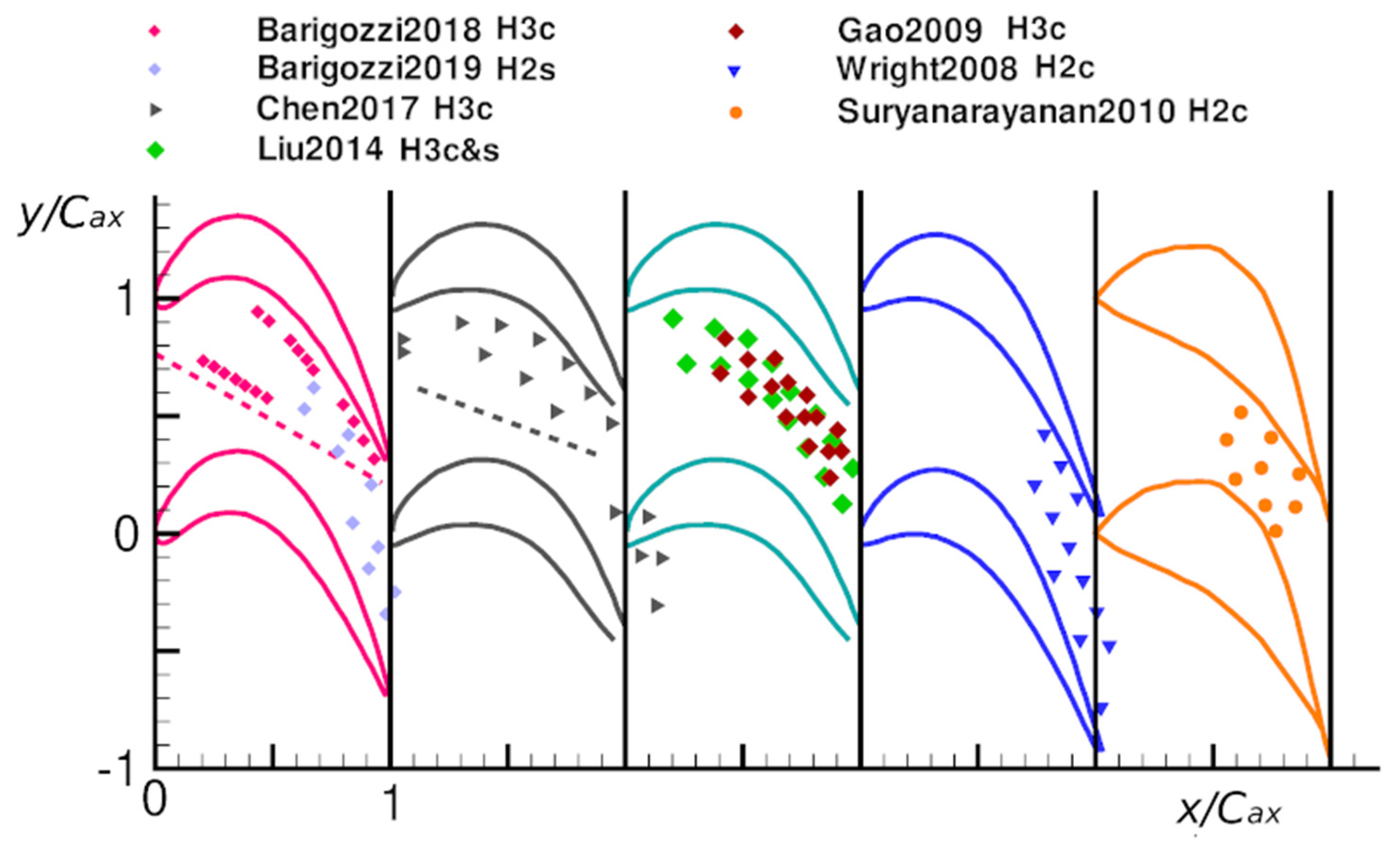
A graphical summary of the pitch averaged cooling effectiveness distributions presented in some of the above-described works is provided in Figure 8. We want to further emphasize that this figure does not attempt to perform a strict comparison among the different performance levels of various techniques, but instead attempts to draw attention toward the macroscopic cooling phenomena that characterize the vortical structure generation and the thermal coverage achieved. In Figure 8a, typical purge flow injected through gaps of different geometries at varying operating conditions are displayed. Coolant effectiveness generally ensures a good protection level till x/Cax ≈ 0.2–0.4. As shown, the downstream region cannot be properly cooled due to the lift-off and washing activity played by the passage vortex, and, thus, discrete holes have to be allocated to protect this region. The cooling holes can be cylindrical, laidback fan-shaped, etc., and clearly different effectiveness is expected for different hole design and positioning (see Figure 8b).
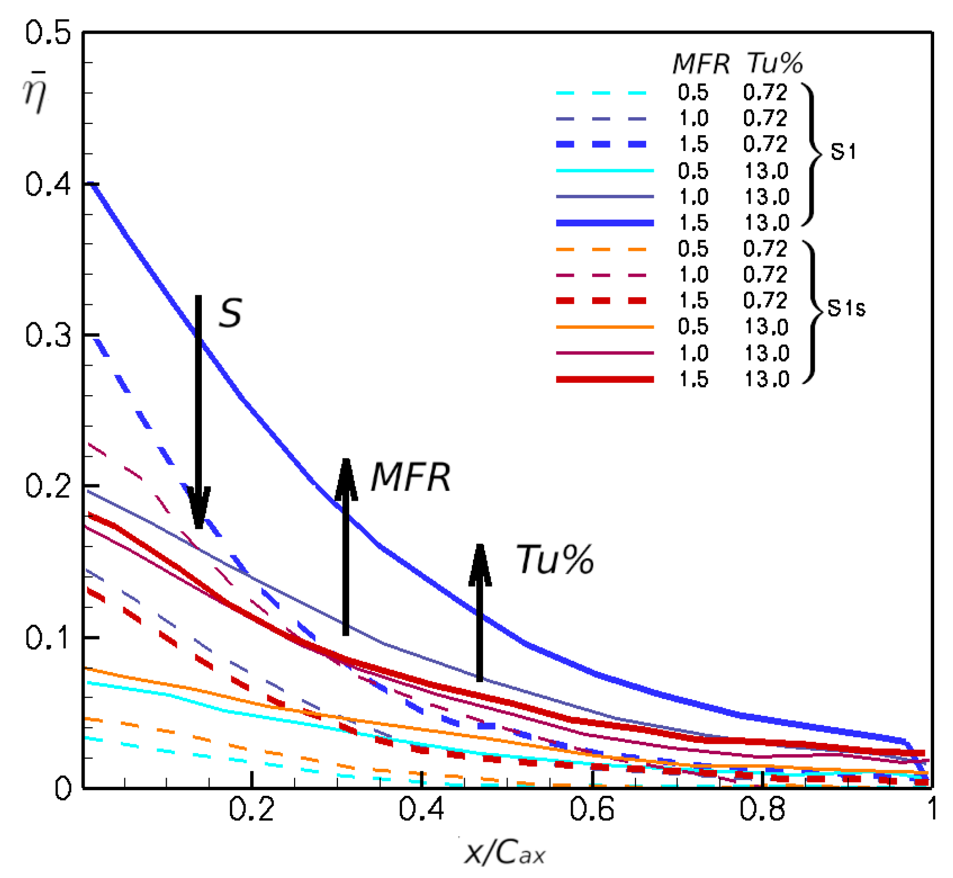
To allow a better comparison between different gap geometries, Figure 9 shows some of the data reported in Figure 8a evidencing the operating conditions (coolant to mainstream mass flow ratio, turbulence intensity, swirling condition). In particular, for consistency, only data coming from [18] have been used to create Figure 9, since the campaign of [18] constitutes quite a complete set. These data support the general conclusion that increasing MFR and Tu% both result into an improvement in effectiveness, both in terms of η level and persistency going downstream. Conversely, a stronger swirl always translates into an effectiveness reduction, that gets stronger at high injection rates. Finally, please note that the reported distributions only extend over the blade passage. This means that the low effectiveness values at x/Cax = 0 probably depend on the gap to leading edge distance of this specific solution, which was not, unfortunately, reported in the original paper [18].
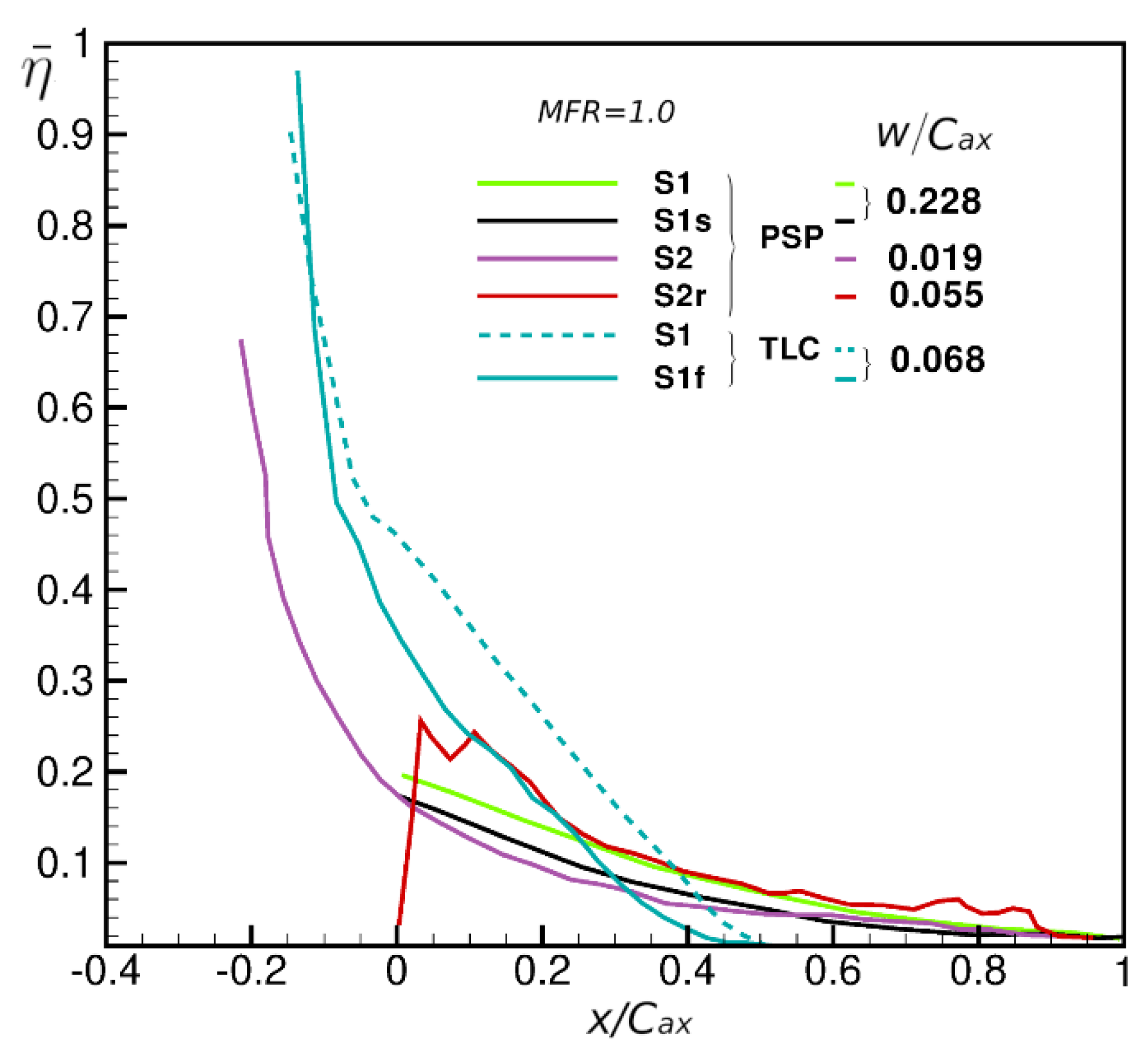
Figure 10 extends the considered data set further, allowing comparison of different slot geometries and locations with respect to the blade leading edge at a fixed MFR of 1%. A general agreement in the decreasing trend of effectiveness inside of the channel can be observed. The same figure also allows different approaches to model purge flow injection through the stator to rotor interface gap, to be compared i.e., simple radial injection across a cavity (S1) or a labyrinth-like cavity (S2), the simulation of purge flow tangential injection using fins (S1f) or swirl generator (S1s) and full rotating rig testing (S2r). Interesting to note is that simulating the rotation effects using fins installed inside the slot can roughly replicate the effectiveness level in a rotating ring with similar slot width and distance from the blade leading edge. Lower effectiveness levels characterize simple slot configuration S1 and labyrinth-like S2 configuration, due to the larger distance from the blade leading edge (unfortunately, data before the leading edge are not available). Swirl simulation reduces the effectiveness level over the whole platform, similarly to the fins effect.
Similarly, Figure 11 compares pitch averaged film cooling effectiveness distributions in the region of discrete hole cooling, i.e., downstream x/Cax = 0.2. In this figure, the different cooling schemes identified in Figure 3 are compared. Please note that H1 refers to holes located only along the blade pressure side, H2 to holes placed rear in the passage, while H3 considers cooling schemes where holes are distributed over most of the platform. Both stationary and rotating rigs (suffix “r”) are considered, while only one case refered to shaped holes (H2s). Clearly, the more upstream the holes are located, the higher is the effectiveness level reached approaching the trailing edge. As a general trend, increasing the blowing ratio translates into an effectiveness reduction when considering cylindrical holes, both for stationary and rotating platforms, due to jet lift-off phenomena. The adoption of shaped holes allows good thermal protection at the rear in the passage, higher than with cylindrical holes. Increasing the density ratio results in higher effectiveness levels, especially in the front of the passage, when injecting coolant across cylindrical holes distributed all over the platform (H3) at a relatively high blowing ratio of 1.5.
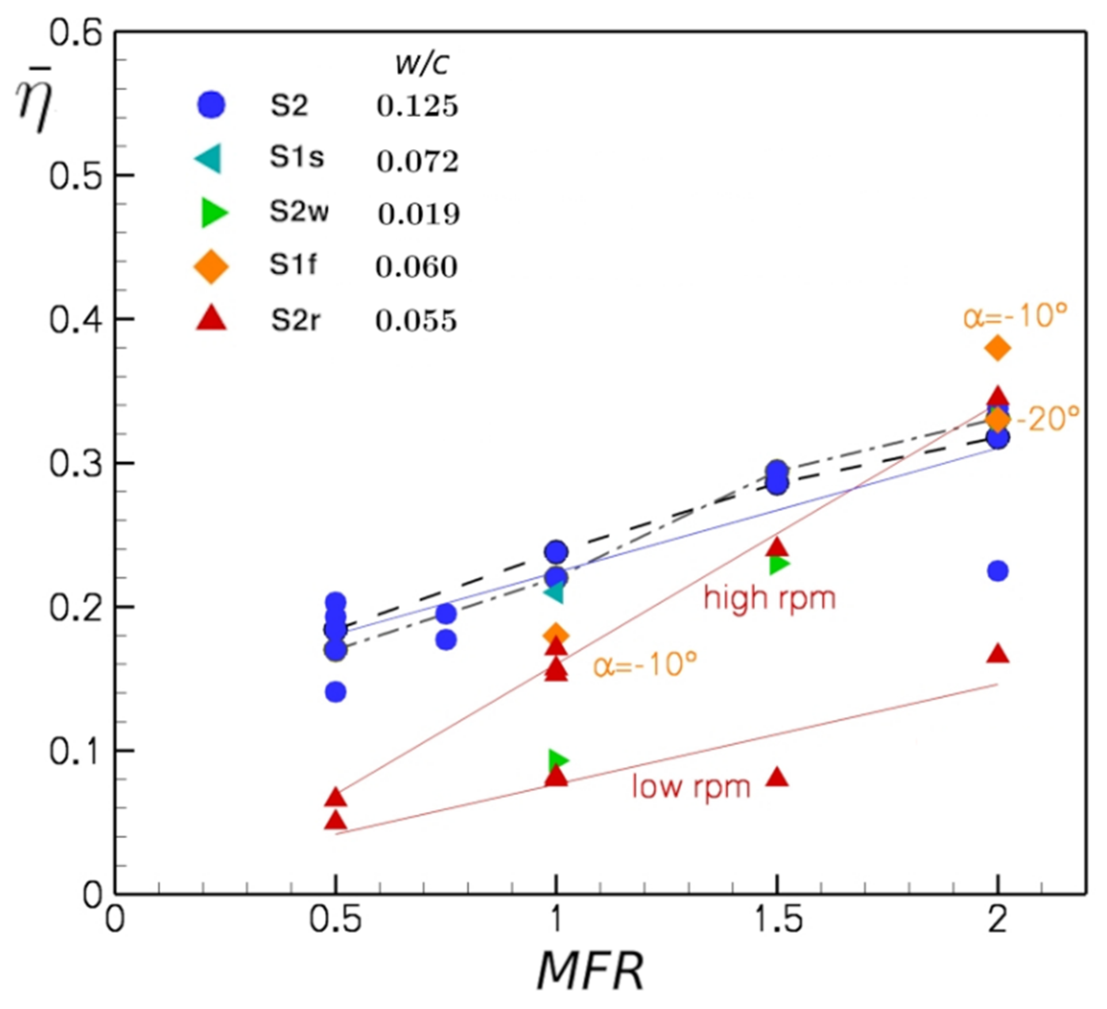
In order to gain a more general understanding of cooling performance achieved by the slot design presented in the open literature, in Figure 12 the pitch-wise averaged film-cooling effectiveness values extracted from Figure 8 at x/Cax = 0.2 are reported as a function of the coolant to mainstream mass flow ratio MFR (density ratio equal to 1 for all the selected data). These data allow better quantification of the impact of operating parameters on purge flow cooling performance. The behaviour of typical purge flow geometries. S2, shown along with the related (linear) minimum least square approximation, demonstrates that increasing the MFR is always beneficial in terms of platform thermal protection. This stands both for stationary and rotating conditions, whatever the rotational speed considered, high or low. As expected, the film-cooling effectiveness of rotating conditions is lower than that of typical stationary configurations, especially when considering low MFR or low rotational speed. The figure also reports data obtained simulating the impact of rotation on the seal flow exiting the gap through fins or swirl generators. These results highlight that well simulated rotation can indeed effectively approximate the effectiveness parameter value.
Finally, Figure 13 reports similar data but for high and low turbulence intensity levels, showing that increasing Tu% is always beneficial for stationary cascades, both simulating the rotation effect or not simulating it and whatever the injection condition. Nevertheless, the impact of an increased mainstream turbulence intensity is significantly reduced when simulating the rotation effect on purge flow discharging from the slot.

6. Phantom Cooling

Recently, a secondary form of cooling, defined as “phantom cooling”, has been the subject of study. This secondary form of cooling is related to coolant streams that mitigate the thermal load in unexpected/unforeseen regions. A small amount of coolant from the blade may go on the end wall, or again from the end wall may cool part of the blade; the coolant flow is mainly carried by the passage vortex and redirected toward the blade suction side providing unintended “phantom” or “secondary” cooling. This phenomenon may be seen as an energy saving mechanism helpful in protecting certain parts of the HPT systems. Ref. [55] observed that phantom cooling may have noticeable effects for SS cooling but also highlighted that the effectiveness could be significantly reduced for higher relative motion conditions. In fact, complex interaction occurs between primary and secondary sources of cooling, as also shown in [59]. Predictions indicate that the unsteadiness phenomena concerned the slot film cooling more than discrete hole cooling; they also highlighted that for rotating speed other than the design value, the film cooling effectiveness decreased, due to either reduced blowing ratio or the stronger effect of the stator wake. Ref. [18] considered the swirl motion effects on phantom cooling, showing a behaviour similar to the one already observed on platform film cooling.

7. Concludings Remarks

The present paper analysed the published literature on rotor platform cooling, considering all aspects involved: from the impact on the aerodynamics to heat transfer behaviour, including both the heat transfer coefficient and the film cooling effectiveness parameters. The published literature provided quite a complete picture of the complex flow phenomena taking place when coolant is injected upstream, through the interference gap, and/or inside the channel. Exhaustive data sets are available for adiabatic film cooling effectiveness from cascade testing, making it possible to identify the most important influencing parameters, i.e., the coolant to mainstream mass flow rate and the mainstream turbulence intensity level, augmentation of which always results in increased effectiveness levels. Nevertheless, the impact of rotation cannot be discarded, to avoid overestimation of platform thermal protection and underestimation of loss generation across the passage. Some improvements can be obtained, thanks to the simulation of coolant swirl or tangential injection: even if effectiveness levels are still overpredicted, the general trends are correctly reproduced, resulting in an acceptable approach to the analysis of rotor platform cooling. Of course, to really capture the complex unsteady flow phenomena taking place at the interface between stator and rotor, a full stage setup would be mandatory, with all the resulting experimental complications. Whatever the adopted approach, all published papers report that purge flow emerging from the stator to rotor interface gap never overcomes the passage vortex separation line, thus requiring the implementation of discrete hole cooling at specific locations. The higher the turbine inlet temperature, the more extended the extra cooling required.
Much less information is available concerning the impact of platform cooling on aerodynamic performance and the platform heat transfer coefficient distribution. Generally speaking, only coolant injected across the gap can interact with secondary flow generation. Purge flow injection, due to its low momentum, always enforces horseshoe and passage vortices, resulting in an increased secondary loss. Again, a correct simulation of rotation effect, particularly of coolant induced inlet flow swirl, is mandatory to obtain a proper estimation of secondary flow enforcement that is stronger due to the relative motion between stator and rotor, since coolant is injected in the passage vortex cross flow direction. The higher the MFR the higher the negative impact on secondary flow.
The number of documented CFD investigations on rotor platform cooling are still limited and, due to the complexity of geometry and flow conditions, they are still performed using conventional numerical approaches.
Certainly, full stage testing, both experimentally and numerically, is the best choice, but it can hardly provide the detailed, and often scaled up information a blade cascade wind tunnel can give. So, further improvement in the capability of linear cascade to approach, as close as possible, real engine conditions should be investigated. Moreover, most of the reported investigations analysed different operating conditions in terms of coolant injection, but not in terms of engine loading. The only exception is the full stage investigation of [29,30], reporting data obtained at variable rotational speeds. Energy transition, with the progressive increase of renewable energy penetration in Europe, is asking industrial gas turbines to act as grid stabilizers, extending the part load operation of these engines down to a progressively lowered minimum operating point. The higher operation flexibility will also impact on manufacturing tolerances of secondary air systems and, particularly, on rim seals, that can undergo dimensional modifications as a consequence of load variation. A better knowledge of coolant to mainstream interaction at rotor inlets in such conditions would help manufacturers in further pushing the limit of gas turbine operability, while still granting sure and safe operation.

Author Contributions

Conceptualization, G.B.; investigation, G.B., H.A., S.R. and N.F.; supervision, G.B. and N.F.; data curation, G.B., H.A., S.R. and N.F.; writing—original draft preparation, G.B., H.A., S.R. and N.F.; writing—review and editing, G.B., H.A., S.R. and N.F. All authors have read and agreed to the published version of the manuscript.

Funding

This research received no external funding.

Data Availability Statement

The data presented in this study are openly available in the open literature, cited and reported in the dedicated References section.

Conflicts of Interest

The authors declare no conflict of interest.

Nomenclature

cblade chord
Dhole diameter
DRdensity ratio
Hblade height
HPThigh pressure turbine
Imomentum flux ratio
Lhole length
mmass flow
M 1 inlet loss free blowing ratio
Mhole blowing ratio
MFRcoolant to mainstream mass flow ratio
Ppressure
PSpressure side
PSPpressure sensitive paints
ReReynolds number
sblade pitch
Sswirl number
SSsuction side
TLCThermochromic liquid crystal
Tuturbulence intensity level
Ulocal mean velocity
X, Y, Zcascade coordinate system
Ytotal pressure loss coefficient
wgap width
αhole injection angle
η adiabatic film cooling effectiveness (local)
{ η } ¯ averaged film cooling effectiveness
ζ local energy loss coefficient
ρ density
Subscripts
axaxial
awadiabatic wall
Ccooling flow
LEleading edge
ttotal
1at cascade inlet
freestream

References

  1. Owen, J.M. Air-cooled gas-turbine discs: A review of recent research. Int. J. Heat Fluid Flow 1988, 9, 354–365. [Google Scholar] [CrossRef]
  2. Phadke, U.P.; Owen, J.M. Aerodynamic aspects of the sealing of gas turbine rotor–stator systems Part 1: The behavior of simple shrouded rotating disk systems in quiescent environment. Int. J. Heat Fluid Flow 1988, 9, 98–105. [Google Scholar] [CrossRef]
  3. Phadke, U.P.; Owen, J.M. Aerodynamic aspects of the sealing of gas turbine rotor–stator systems Part 2: The behavior of simple seals in a quasi- axisymmetric external flow. Int. J. Heat Fluid Flow 1988, 9, 106–112. [Google Scholar] [CrossRef]
  4. Phadke, U.P.; Owen, J.M. Aerodynamic aspects of the sealing of gas turbine rotor–stator systems Part 3: The effect of non-axisymmetric external flow on seal performance. Int. J. Heat Fluid Flow 1988, 9, 113–117. [Google Scholar] [CrossRef]
  5. Ahn, J.; Schobeiri, M.T.; Han, J.-C.; Moon, H.-K. Film cooling effectiveness on the leading edge region of a rotating turbine blade with two rows of film cooling holes using pressure sensitive paint. J. Heat Transf. 2006, 128, 879–888. [Google Scholar] [CrossRef]
  6. Abhari, R.S.; Epstein, A.H. An Experimental Study of Film Cooling in a Rotating Transonic Turbine. ASME J. Turbomach. 1994, 116, 63–70. [Google Scholar] [CrossRef]
  7. Yin, F.; Rao, A.G. Performance analysis of an aero engine with inter-stage turbine burner. Aeronaut. J. 2017, 121, 1605–1626. [Google Scholar] [CrossRef] [Green Version]
  8. Jenny, P.; Lenherr, C.; Abhari, R.S.; Kalfas, A. Effect of hot streak migration on unsteady blade row interaction in an axial turbine. J. Turbomach. 2012, 134, 1–9. [Google Scholar] [CrossRef]
  9. Abba, L.; Abram, R.; Barigozzi, G.; Perdichizzi, A. Design, Validation and Verification of Film Cooling on Gas Turbine Rotor Endwall. In Proceedings of the ASME Turbo Expo, Düsseldorf, Germany, 16–20 June 2014; Paper No GT2014-25621. pp. 1–8. [Google Scholar] [CrossRef]
  10. Downs, J.; Landis, K. Turbine Cooling Systems Design: Past, Present and Future. In Proceedings of the ASME Turbo Expo, Orlando, FL, USA, 8–12 June 2009; Paper No GT2009-59991. pp. 819–828. [Google Scholar]
  11. Dunn, M.G.; Haldeman, C.W. Time-averaged heat flux for a recessed tip, lip, platform of a transonic turbine blade. J. Turbomach. 2000, 122, 692–698. [Google Scholar] [CrossRef]
  12. Wright, L.M.; Malak, M.F.; Crites, D.C.; Morris, M.C.; Yelavkar, V.; Bilwani, R. Review of Platform Cooling Technology for High Pressure Turbine Blades. In Proceedings of the ASME Turbo Expo, Düsseldorf, Germany, 16–20 June 2014; Paper No. GT2014-26373. pp. 1–12. [Google Scholar]
  13. Gao, Z.; Narzary, D.; Han, J.C. Turbine blade platform film cooling with typical stator-rotor purge flow and discrete-hole film cooling. J. Turbomach. 2009, 131, 041004. [Google Scholar] [CrossRef]
  14. Liu, K.; Yang, S.F.; Han, J.C. Influence of coolant density on turbine platform film-cooling with stator-rotor purge flow and compound-angle holes. J. Therm. Sci. Eng. Appl. 2014, 6, 041007. [Google Scholar] [CrossRef]
  15. Narzary, D.P.; Liu, K.-C.; Han, J.-C. Influence of coolant density on turbine blade platform film-cooling. J. Therm. Sci. Eng. Appl. 2012, 4, 021002. [Google Scholar] [CrossRef]
  16. Chen, A.F.; Shiau, C.C.; Han, J.C. Turbine blade platform film cooling with simulated swirl purge flow and slashface leakage conditions. J. Turbomach. 2017, 139, 031012. [Google Scholar] [CrossRef]
  17. Li, S.J.; Lee, J.; Han, J.C.; Zhang, L.; Moon, H.K. Turbine platform cooling and blade suction surface phantom cooling from simulated swirl purge flow. J. Turbomach. 2016, 138, 081004. [Google Scholar] [CrossRef]
  18. Li, S.J.; Lee, J.; Han, J.C.; Zhang, L.; Moon, H.K. Influence of mainstream turbulence on turbine blade platform cooling from simulated swirl purge flow. Appl. Therm. Eng. 2016, 101, 678–685. [Google Scholar] [CrossRef]
  19. Wright, L.M.; Blake, S.A.; Han, J.C. Film cooling effectiveness distributions on a turbine blade cascade platform with stator-rotor purge and discrete film hole flows. J. Turbomach. 2008, 130, 031015. [Google Scholar] [CrossRef]
  20. Wright, L.M.; Blake, S.A.; Rhee, D.H.; Han, J.C. Effect of upstream wake with vortex on turbine blade platform film cooling with simulated stator-rotor purge flow. J. Turbomach. 2009, 131, 021017. [Google Scholar] [CrossRef]
  21. Barigozzi, G.; Fontaneto, F.; Franchini, G.; Perdichizzi, A.; Maritano, M.; Abram, R. Influence of Coolant Flow Rate on Aero-Thermal Performance of a Rotor Blade Cascade with Endwall Film Cooling. J. Turbomach. 2012, 134, 051038. [Google Scholar] [CrossRef]
  22. Barigozzi, G.; Franchini, G.; Perdichizzi, A.; Maritano, M.; Abram, R. Purge flow and interface gap geometry influence on the aero-thermal performance of a rotor blade cascade. Int. J. Heat Fluid Flow 2013, 44, 563–575. [Google Scholar] [CrossRef]
  23. Barigozzi, G.; Franchini, G.; Perdichizzi, A.; Maritano, M.; Abram, R. Influence of Purge Flow Injection Angle on the Aero-Thermal Performance of a Rotor Blade Cascade. J. Turbomach. 2014, 136, 041012. [Google Scholar] [CrossRef]
  24. Barigozzi, G.; Perdichizzi, A.; Abram, R. Improving the Film Cooling of a Rotor Blade Platform. J. Fluids Eng. 2018, 140, 021101. [Google Scholar] [CrossRef]
  25. Barigozzi, G.; Fontaneto, F.; Franchini, G.; Perdichizzi, A.; Maritano, M.; Abram, R. Influence of hole diameter and fan shaping on film cooling of a rotor blade cascade. In Proceedings of the 14th International Symposium on Transport Phenomena and Dynamics of Rotating Machinery (ISROMAC-14), Honolulu, HI, USA, 27 February–2 March 2012. [Google Scholar]
  26. Barigozzi, G.; Perdichizzi, A.; Abram, L.P.-R. Combined Experimental and Numerical Investigation of the Aero-Thermal Performance of a Rotor Blade Cascade with Platform Cooling. In Proceedings of the ASME Turbo Expo, Phoenix, AZ, USA, 17–21 June 2019. Paper No GT2019-91601. [Google Scholar]
  27. Popovíc, I.; Hodson, H.P. Aerothermal impact of the interaction between hub leakage and mainstream flows in highly-loaded high pressure turbine blades. J. Turbomach. 2013, 135, 061014. [Google Scholar] [CrossRef]
  28. Popović, I.; Hodson, H.P.; Janke, E.; Wolf, T. The effects of unsteadiness and compressibility on the interaction between hub leakage and mainstream flows in high-pressure turbines. J. Turbomach. 2013, 135, 061015. [Google Scholar] [CrossRef]
  29. Suryanarayanan, A.; Mhetras, S.P.; Schobeiri, M.T.; Han, J.C. Film cooling effectiveness on a rotating blade platform. J. Turbomach. 2009, 131, 011014. [Google Scholar] [CrossRef]
  30. Suryanarayanan, A.; Ozturk, B.; Schobeiri, M.T.; Han, J.C. Film-cooling effectiveness on a rotating turbine platform using pressure sensitive paint technique. J. Turbomach. 2010, 132, 041001. [Google Scholar] [CrossRef]
  31. Pau, M.; Paniagua, G.; Delhaye, D.; de la Loma, A.; Ginibre, P. Aerothermal impact of stator-rim purge flow and rotor-platform film cooling on a transonic turbine stage. J. Turbomach. 2010, 132, 021006. [Google Scholar] [CrossRef]
  32. Green, B.R.; Mathison, R.M.; Dunn, M.G. Time-averaged and Time-accurate Aerodynamic Effects of Forward Rotor Cavity Purge Flow for a High-pressure Turbine-Part I: Analytical and Experimental Comparisons. In Proceedings of the ASME Turbo Expo, Copenhagen, Denmark, 11–15 June 2012. Paper No GT2012-69937. [Google Scholar]
  33. Green, B.R.; Mathison, R.M.; Dunn, M.G. Time-averaged and Time-accurate Aerodynamic Effects of Rotor Purge Flow for a Modern, One and One-half Stage High-pressure Turbine-Part II: Analytical Flow Field Analysis. In Proceedings of the ASME Turbo Expo, Copenhagen, Denmark, 11–15 June 2012; 2012. Paper No GT2012-69939. [Google Scholar]
  34. Nickol, J.; Tomko, M.; Mathison, R.; Liu, J.S.; Morris, M.; Malak, M.F. Heat Transfer and Pressure Measurements for the Forward Purge Cavity, Inner Endwall, and Rotor Platform of a Cooled Transonic Turbine Stage. In Proceedings of the ASME Turbo Expo, Oslo, Norway, 11–15 June 2018. Paper No GT2018-76978. [Google Scholar]
  35. Schuepbach, R.S.; Abhari, M.G.; Rose, T.; Germain, I.; Raab, J.G. Effects of Suction and Injection Purge-Flow on the Secondary Flow Structures of a High-Work Turbine. J. Turbomach. 2010, 132, 021021. [Google Scholar] [CrossRef]
  36. Regina, K.; Kalfas, A.I. Experimental investigation of purge flow effects on a high pressure turbine stage. J. Turbomach. 2015, 135, 1–8. [Google Scholar] [CrossRef]
  37. Schreiner, B.D.J.; Wilson, M.; Li, Y.S.; Sangan, C.M. Effect of purge on secondary flow-field of a gas turbine blade-row. J. Turbomach. 2020, 142, 101006. [Google Scholar] [CrossRef]
  38. Figueiredo, A.J.C.; Schreiner, B.D.J.; Mesny, A.W.; Pountney, O.J.; Scobie, J.A.; Li, Y.S.; Cleaver, D.J.; Sangan, C.M. Volumetric velocimetry measurements of purge-mainstream interaction in a one-stage turbine. J. Turbomach. 2021, 143, 1–14. [Google Scholar] [CrossRef]
  39. Scobie, J.A.; Hualca, F.P.; Sangan, C.M.; Lock, G.D. Egress interaction through turbine rim seal. J. Eng. Gas Turbines Power 2018, 140, 1–9. [Google Scholar] [CrossRef]
  40. Langston, L.S. Crossflows in a turbine cascade passage. J. Eng. Power 1980, 102, 866–874. [Google Scholar] [CrossRef]
  41. Goldstein, R.J.; Spores, R.A. Turbulent Transport on the Endwall in the Region Between Adjacent Turbine Blades. J. Heat Transf. 1988, 110, 862–869. [Google Scholar] [CrossRef]
  42. Sharma, O.P.; Butler, T.L. Predictions of Endwall Losses and Secondary Flows in Axial Flow Turbine Cascades. J. Turbomach. 1987, 109, 229–236. [Google Scholar] [CrossRef]
  43. Wang, H.-P.; Olson, S.J.; Goldstein, R.J.; Eckert, E.R.G. Flow Visualization in a Linear Turbine Cascade of High- Performance Turbine Blades. J. Turbomach. 1997, 119, 1–8. [Google Scholar] [CrossRef]
  44. Ligrani, P.; Potts, G.; Fatemi, A. Endwall aerodynamic losses from turbine components within gas turbine engines. Propuls. Power Res. 2017, 6, 1–14. [Google Scholar] [CrossRef]
  45. Bindon, J.P. Exit Plane and Suction Surface Flows in an Annular Turbine Cascade with a Skewed Inlet Boundary Layer. Int. J. Heat Fluid Flow 1980, 2, 57–66. [Google Scholar] [CrossRef]
  46. Boletis, E.; Sieverding, C.H.; van Hove, W. Effect of Skewed Inlet Endwall Boundary Layer on the 3D-Flowfield in an Annular Cascade. In Proceedings of the Propulsion and Energetics Panel 61st (A), Copenhagn, Denmark, 1–3 June 1983; 1983. Paper No. AGARD-CP-351. [Google Scholar]
  47. Walsh, J.A.; Gregory-Smith, D.G. Inlet skew and the growth of secondary losses and vorticity in a turbine cascade. J. Turbomach. 1990, 112, 633–642. [Google Scholar] [CrossRef]
  48. Papa, M.; Srinivasan, V.; Goldstein, R.J. Film cooling effect of rotor-stator purge flow on endwall heat/mass transfer. J. Turbomach. 2012, 134, 041014. [Google Scholar] [CrossRef]
  49. Graziani, R.A.; Blair, M.F.; Taylor, J.R.; Mayle, R.E. An experimental study of endwall and airfoil surface heat transfer in a large scale turbine blade cascade. J. Eng. Power 1980, 102, 257–267. [Google Scholar] [CrossRef]
  50. McLean, C.; Camci, C.; Glezer, B. Mainstream aerodynamic effects due to wheelspace coolant injection in a high-pressure turbine stage: Part I-Aerodynamic measurements in the stationary frame. J. Turbomach. 2001, 123, 687–696. [Google Scholar] [CrossRef]
  51. Ong, J.; Miller, R.J.; Uchida, S. The Effect of Coolant Injection on the Endwall Flow of a High Pressure Turbine. J. Turbomach. 2012, 134, 051003. [Google Scholar] [CrossRef]
  52. Lynch, S.P.; Thole, K.A.; Kohli, A.; Lehane, C.; Praisner, T. Aerodynamic Loss for a Turbine Blade with Endwall Leakage Features and Contouring. In Proceedings of the ASME Turbo Expo, San Antonio, TX, USA, 3–7 June 2013. Paper No GT2013-94943. [Google Scholar] [CrossRef]
  53. Narzary, D.P.; Liu, K.C.; Rallabandi, A.P.; Han, J.C. Influence of coolant density on turbine blade film-cooling using pressure sensitive paint technique. J. Turbomach. 2012, 134, 031006. [Google Scholar] [CrossRef]
  54. Chen, A.F.; Shiau, C.C.; Han, J.C. Turbine blade platform film cooling with fan-shaped holes under simulated swirl purge flow and slashface leakage conditions. J. Turbomach. 2018, 140, 011006. [Google Scholar] [CrossRef]
  55. Zhang, K.; Li, J.; Li, Z.; Song, L. Effects of simulated swirl purge flow and mid-passage gap leakage on turbine blade platform cooling and suction surface phantom cooling performance. Int. J. Heat Mass Transf. 2019, 129, 618–634. [Google Scholar] [CrossRef]
  56. Yang, H.; Gao, Z.; Chen, H.C.; Han, J.C.; Schobeir, M.T. Prediction of film cooling and heat transfer on a rotating blade platform with stator-rotor purge and discrete film-hole flows in a 1-1/2 turbine stage. J. Turbomach. 2009, 131, 041003. [Google Scholar] [CrossRef]
  57. Reid, K.; Denton, J.; Pullan, G.; Curtis, E.; Longley, J. The interaction of turbine inter-platform leakage flow with the mainstream flow. J. Turbomach. 2007, 129, 303–310. [Google Scholar] [CrossRef]
  58. Lynch, S.P.; Thole, K.A. Heat Transfer and film cooling on a contoured blade endwall with platform gap leakage. J. Turbomach. 2017, 139, 051002. [Google Scholar] [CrossRef]
  59. Yang, X.; Liu, Z.; Liu, Z.; Feng, Z.; Simon, T. Turbine platform phantom cooling from airfoil film coolant with purge flow. Int. J. Heat Mass Transf. 2019, 140, 25–40. [Google Scholar] [CrossRef]
Figure 1. Linear and rotating cascades examples: (a) Sketch of rotor platform cooling flows [39] (b) Five blade rotor cascade [16], (c) Seven blade rotor cascade [24,25], (d) Turbine rotor component with stator cavity and labyrinth seal of TPFL [29,30].
Ijtpp 07 00022 g001
Figure 2. Typical slot configurations: (a) S1f [22], (b) S2 [13] and (c) S1s [18].
Ijtpp 07 00022 g002
Figure 3. Discrete cooling hole locations in the blade passage.
Ijtpp 07 00022 g003
Figure 4. Three-dimensional flow field in the end wall region: secondary flow vortex structure as proposed by [42].
Ijtpp 07 00022 g004
Figure 5. Skewed flow due to rotational effect: (a) schematic of cascade inlet flow condition and (b) simulated streamlines issuing from a stator to rotor gap from Green et al., 2012, side view—not to be scaled as reported in [33] (c) simulated streamlines issuing from a stator to rotor forward looking after side view—not to be scaled as reported in [33].
Ijtpp 07 00022 g005
Figure 6. Overall losses due to leakage: (a) Local kinetic energy loss distribution measured at x/Cax = 108% and MFR = 1% (top), platform configuration (mid) and mixed-out loss coefficient (bottom) by [22] and (b) total pressure loss coefficient lines superimposed over flood contours measured at x/Cax = 150% for leakage concentration of 1% (top), rim seal configuration (mid) and aerodynamic losses and sealing effectiveness (bottom) by [28].
Ijtpp 07 00022 g006
Figure 7. Comparison between stage and cascade results at MFR = 1%: (a) three different rotational tests [29] (b) static test without fins [23] and (c) static test with simulated rotational effects by inclined fins (−10°) [23].
Ijtpp 07 00022 g007aIjtpp 07 00022 g007b
Figure 8. Rotor platform film cooling effectiveness: (a) purge flow only, S1, S1s [18], S1f [22], [S2]-magenta line [19], S2 purple line [20], S2r [29] and (b) purge flow and discrete holes presented in the open literature S1s-H3 [16], S2-H2 [19], S2-H3 [15], S2-H3c/s [14], S2r-H2 [30].
Ijtpp 07 00022 g008aIjtpp 07 00022 g008b
Figure 9. Platform rotor blade film cooling effectiveness as a function of operating conditions (figure newly created herein using data taken from [18]).
Ijtpp 07 00022 g009
Figure 10. Rotor platform pitch averaged film cooling effectiveness at MFR = 1.0% for different cooling slot configurations: S2r at design rotational speed [29], S1 and S1f with −10° fins [22], S1 and S1s with SR = 0.4 [17], S2 with simulated stator effect [20].
Ijtpp 07 00022 g010
Figure 11. Platform rotor blade film cooling effectiveness as a function of operating conditions—data reproduced: H2c from [19], H2cr from [30], H3c from [15], H2s from [26].
Ijtpp 07 00022 g011
Figure 12. Platform rotor blade film cooling effectiveness (extracted at x/Cax = 20%) as a function of the mass flow ratio with density ratio DR = 1 (S2 [13,14,15,19], S1s [16], S2w [20], S1f [22], S2r [29,30]).
Ijtpp 07 00022 g012
Figure 13. Platform rotor blade film cooling effectiveness (measured at x/Cax = 20%) as a function of the mass flow ratio with density ratio DR = 1.5—turbulence effect—Tu% = 0.72 & 13 (figure newly created herein using data taken from [18]).
Ijtpp 07 00022 g013
Table 1. Typical slot geometry and details of purge flow supply system.
Reference Studyw/CaxL/sxLE/CaxCode
Gao et al., 2009 [13]; Liu et al., 2014 [14]; Narzary et al., 2012 [15]0.1251.50.076S2
Chen et al., 2017 [16]0.07230.072S1s
Wright et al., 2008 [19]0.0191.50.225S2
Wright et al., 2009 [20]S2w
Suryanarayanan et al., 2010 [30]0.055-0.120S2r
(Li et al., 2016) [18]0.2284.1-S1s
(Barigozzi et al., 2013, 2014) [22,23]0.068–0.1273.40.146S1f
Table 2. Typical hole geometrical parameters.
Reference StudyD (mm)L/DD/CaxαCode
Gao et al., 2009 [13]; Liu et al., 2014 [14]; Narzary et al., 2012 [15]1.680.01930°H3c&s
Chen et al., 2017 [16]1.680.01930°H3c
Wright et al., 2008 [19]2.510.160.01530°H2c
Barigozzi et al., 2012, 2018 [21,24]0.720 ÷ 480.006811.5°H1c
Suryanarayanan et al., 2010 [30]1.0-0.02435° ÷ 37°H2c
(Barigozzi et al., 2012) [25]1.014 ÷ 340.009840°H3s
(Barigozzi et al., 2019) [26]1.0200.009830°H2s
Table 3. Summary of considered literature—aerodynamic aspects.
Reference StudyExp./Num.Flow RegimeTu%MFR (%)Code
Pau et al., 2010 [31]BothVariable rpm
Re = 1.1 × 10⁶
-−0.1 ÷ 0.8
0.02–0.043
S2r
H2r
Green et al., 2012 [32,33]Both--0.72S2r
Ong et al., 2012 [51]BothRe1 = 3.7 × 10⁵-1.33S2r
Regina and Kalfas, 2015 [36]Exp.Re = 3.8 × 10⁵-−0.1 ÷ 1.2S2r
Nickol et al., 2018 [34]Exp.Transonic-5.3 ÷ 8 also including blade coolingS2r
Schreiner et al., 2020 [37]BothRe = 7.2 × 10⁵-1.7 (DR = 1.5)S2r
McLean et al., 2001 [50]Exp.Re1 = 3–5 × 10⁵-1 ÷ 1.5S1r
Papa et al., 2011 [48]Exp.Re = 6 × 1050.2–4M = 0.5 ÷ 1.5S1
Popovic et al., 2013 [28]Num.Re = 5 × 1050.51.5S2s
Lynch et al., 2013 [52]Exp.Re = 2 × 10560.75S1s
H3c
Inter platform gap
Barigozzi et al., 2013, 2014 [22,23]Exp.Re = 7.4 × 1050.60.3 ÷ 2S1f
Barigozzi et al., 2019 [26]BothRe = 7.4 × 1057.60.09 ÷ 0.27H2s
Table 4. Summary of considered literature—thermal aspects.
Reference StudyExp./Num.Flow RegimeMFR%DRTu%Code
Pau et al., 2010 [31]BothRe = 1.1 × 1060 ÷ 0.8--S2r
Wright et al., 2008 [19]ExpRe1 = 3.1 × 105210.75S2-H2
Wright et al., 2009 [20]ExpRe1 = 3.1 × 1050.5 ÷ 215S2
Gao et al., 2009 [13]ExpRe = 7.5 × 1050, 0.7511.75S2-H2s
Narzary et al., 2012 [53]Exp.Mid speed0.25 ÷ 0.751.1, 24.2, 10.5S2-H3
Liu et al., 2014 [14]Exp.Mid speed0.51, 24.2, 10.5S2-H3s
Li et al., 2016 [18]Exp.Re1 = 2.5 × 1050.5 ÷ 1.51.50.72 ÷ 13S2-H3(c&s)
Li et al., 2016 [17]Exp.Re1 = 2.5 × 1050.5 ÷ 1.51.50.7S1s
Chen et al., 2017 [16]Exp.Re = 7.2 × 1050.5 ÷ 11 ÷ 210.5S1s
Chen et al., 2018 [54]Exp.Re = 7.5 × 1050.75 ÷ 11–210.5S1s-H3
Barigozzi et al., 2012 [21]Exp.Re = 7.4 × 10⁵M1 = 0 ÷410.6S1s-H3s
Barigozzi et al., 2013, 2014 [22,23]Exp.Re = 7.4 × 1050.3 ÷ 210.6H1
Barigozzi et al., 2018 [24]Exp.Re = 7.4 × 10⁵M1 = 1 ÷ 210.6S1f
Barigozzi et al., 2019 [26]BothRe = 7.4 × 1050.09 ÷ 0.2717.6H2s
Suryanarayanan et al., 2010 [30]Exp.Variable rpm1.0 (slot)
0.5 ÷ 2 (holes)
1-S2-H2s_r
Yang et al., 2009 [59]Num.Re = 6 × 1062 ÷ 41.78-S2-H2_r
Lynch and Thole, 2017 [58]Exp.Re = 2 × 1050.7516S1
Publisher’s Note: MDPI stays neutral with regard to jurisdictional claims in published maps and institutional affiliations.

