

Advanced Gas Turbine Cooling for the Carbon-Neutral Era


Abstract
1. Introduction
2. Historical Development of Industrial Gas Turbines
2.1. Development of Large Industrial Gas Turbines to Date
2.2. Development of Small and Medium Industrial Gas Turbines to Date
2.3. Integrated Gasification Combined Cycle (IGCC) Technologies
2.4. Future Development of CCGTs, or What Is a CCGT in Line with the Carbon-Neutral Era?
3. Industrial Gas Turbines of the Future
3.1. Hydrogen and Ammonia as Gas Turbine Fuels
- If both the power output and the exhaust gas temperature have to remain constant while burning 100% hydrogen, the TIT increases by several dozens of degrees with the subsequent impact on the average component temperature.
- If both the TIT and the exhaust gas temperature remain constant, the power output of the gas turbine will decrease by more than 10%, but the efficiency will increase slightly and the exhaust gas mass flow substantially.
- If the power output and the TIT remain constant, the exhaust gas temperature will decrease by nearly 20 K, but again, both the gas turbine efficiency will increase slightly and the exhaust gas mass flow substantially.
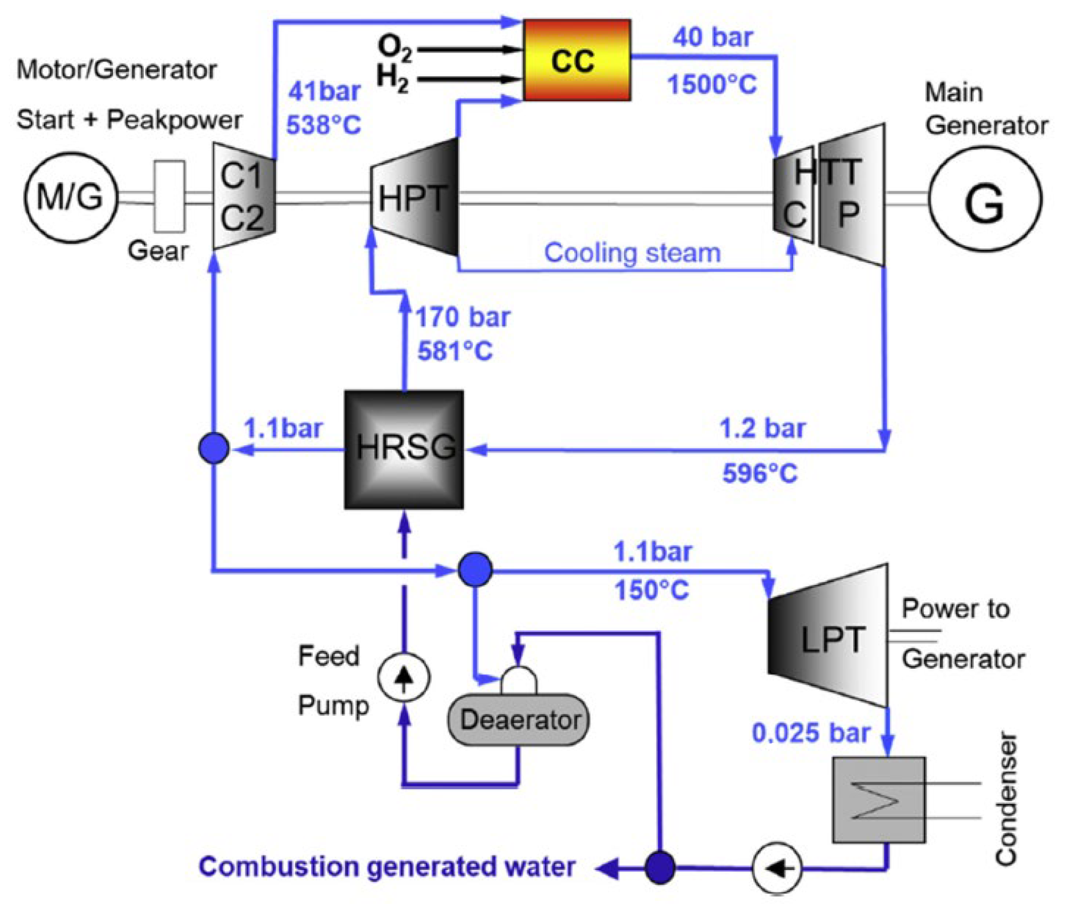
3.2. Oxy-Fuel and Hydrogen-Oxy Cycle Combustion Turbine
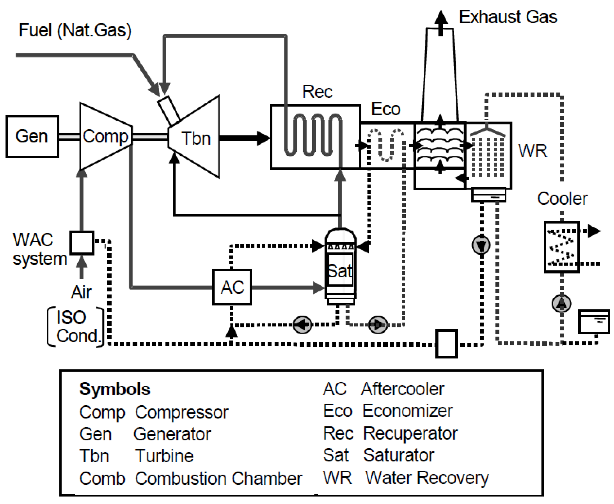
3.3. The HAT Cycle
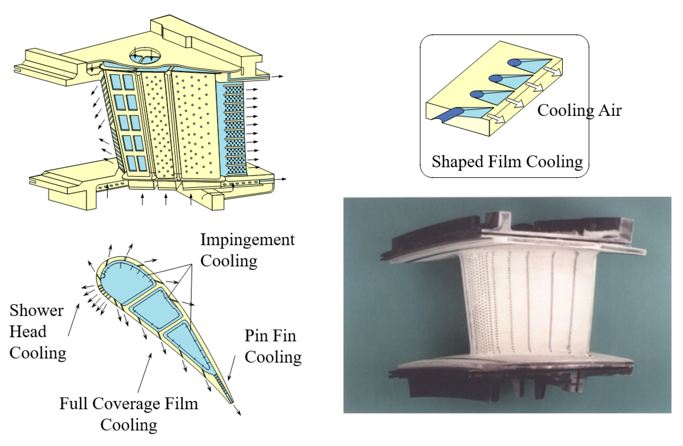
4. Cooling Structure for Gas Turbine Airfoils of Future Importance
5. Additive Manufacturing
5.1. Materials’ Science
5.2. Impingement Cooling
5.3. Internal Cooling
5.4. Film Cooling
5.5. Deviations, Tolerances and Roughness
6. Double-Wall Cooling
7. Conclusions
Author Contributions
Funding
Conflicts of Interest
Nomenclature and Acronyms
| D | Impingement-cooling hole diameter |
| d | film-cooling hole diameter |
| M | film-cooling hole blowing ratio: ρcuc/ρ∞u∞ |
| Nu | Nusselt number |
| Re | Reynolds number |
| u | velocity |
| x | horizontal (in-plane) axis/direction of flat plate |
| y | horizontal (in-plane) axis/direction of flat plate |
| z | vertical (out-of-plane) axis/direction of flat plate |
| δ | boundary layer thickness |
| ρ | density |
| Subscripts | |
| c | coolant |
| f | film |
| ∞ | mail stream |
| Abbreviations | |
| ABB | Asea Brown Boveri |
| AHAT | humid air turbine |
| AM | additive manufacturing |
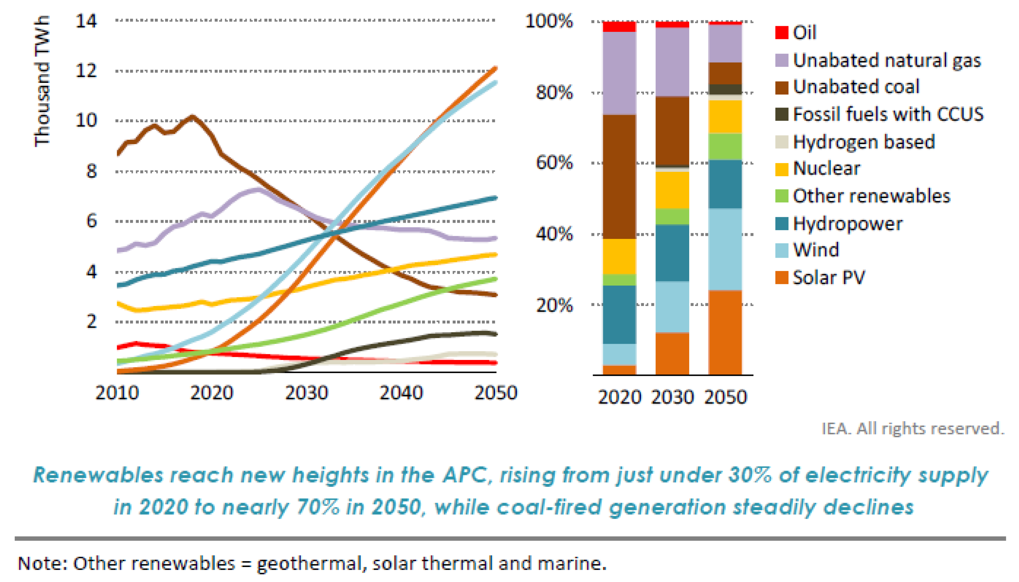
| APC | announced pledges case |
| ATS | advanced turbine systems |
| BBC | Brown, Boveri & Company |
| CC | conventional casting |
| CC | combined cycle |
| CCGT | combined cycle gas turbine |
| CFD | computational fluid dynamic |
| CHP | combined heat and power |
| CCS | carbon capture and storage |
| CCUS | carbon capture usage and storage |
| COP | Conference of the Parties |
| DOE | department of energy |
| DS | dictionary solidified |
| DWC DWTC | double-wall cooling double wall transpiration cooling |
| EDM | electric discharge machining |
| EPRI | Electric Power Research Institute |
| ERDA FE | Energy Research and Development Administration Finite element |
| FEA FFT | finite element analysis Fast Fourier Transform |
| GE | General Electric Corporation |
| GHG | greenhouse gas emissions |
| GT | gas turbine |
| GTW | gas turbine world |
| HAT | humid air turbine |
| HHV | high heating value |
| HRSG | heat recovery steam generator |
| HTTT | High Temperature Turbine Technology |
| IEA | International Energy Agency |
| IGCC | integrated gasification combined cycle |
| LCF | low cycle fatigue |
| LNG | liquid natural gas |
| LHV | low heating value |
| MHI | Mitsubishi Heavy Industries, Ltd. |
| MRI | magnetic resonance imaging |
| NDC | nationally determined contribution |
| NGV | nozzle guide vane |
| OEM | original equipment manufacturing |
| OFC | oxy-fuel cycle |
| PIV | particle image velocimetry |
| PHR | power-to-heat ratio |
| PW | Pratt and Whitney |
| SCGT | steam-cooling gas turbine |
| SLM | selective laser melting |
| STIG | steam-injected gas turbine |
| TBC | thermal barrier coating |
| TIT | turbine inlet temperature |
| UCTS | uniform crystal temperature sensors |
| VG | vortex generator |
| WH | Westinghouse Electric Company |
References
- United Nations Climate Actions. The Paris Agreement. Available online: https://www.un.org/en/climatechange/paris-agreement (accessed on 24 December 2022).
- United Nations Climate Change. Long-Term Strategies Portal. Available online: https://unfccc.int/process/the-paris-agreement/long-term-strategies (accessed on 24 December 2022).
- The Government of Japan. The Long-Term Strategy under the Paris Agreement. 2021. Available online: https://unfccc.int/sites/default/files/resource/Japan_LTS2021.pdf (accessed on 9 October 2022).
- Regulation (EU) 2021/1119 of the European Parliament and of the Council of 30 June 2021 Establishing the Framework for Achieving Climate Neutrality and Amending Regulations (EC) No 401/2009 and (EU) 2018/1999 (‘European Climate Law’). Available online: https://eur-lex.europa.eu/legal-content/EN/TXT/?uri=CELEX:32021R1119 (accessed on 24 December 2022).
- A European Green Deal. Striving to Be the First Climate-Neutral Continent. 2019. Available online: https://commission.europa.eu/strategy-and-policy/priorities-2019-2024/european-green-deal_en (accessed on 24 December 2022).
- EIB Group Climate Bank Roadmap 2021–2025. 2020. Available online: https://www.eib.org/en/publications/the-eib-group-climate-bank-roadmap (accessed on 24 December 2022).
- GE’s 7 HA and 9 HA Plants Rated at More than 61% CC Efficiency. Available online: https://www.mcilvainecompany.com (accessed on 24 December 2022).
- Takamura, K.; Iijima, T.; Wakazono, S.; Hada, S.; Yuri, M.; Kataoka, M. Development of 1650 °C Class Next Generation JAC Gas Turbine based on J Experience. Mitsubishi Heavy Ind. Tech. Rev. 2019, 56, 1–9. Available online: https://www.mhi.co.jp/technology/review/pdf/e563/e563020.pdf (accessed on 11 October 2022).
- ASME. The World’s First Industrial Gas Turbine Set at Neuchâtel (1939), An International Historic Mechanical Engineering Landmark, 2 September 1988, Neuchâtel, Switzerland. Available online: https://www.asme.org/wwwasmeorg/media/resourcefiles/aboutasme/who%20we%20are/engineering%20history/landmarks/135-neuchatel-gas-turbine.pdf (accessed on 24 December 2022).
- Wettstein, H.E. 80 years open GT development in Baden. In Proceedings of the ASME Turbo Expo 2019, Phoenix, AZ, USA, 17–21 June 2019. Paper No. GT2019-90177. [Google Scholar] [CrossRef]
- Meher-Homji, C.B. The Development of the Whittle Turbojet. ASME J. Eng. Gas Turbines Power 1998, 120, 249–256. [Google Scholar] [CrossRef]
- Meher-Homji, C.B.; Prisell, E. Pioneering turbojet developments of Dr. Hans Von Ohain—From the HeS 1 to the HeS 011. J. Eng. Gas Turbines Power 2000, 122, 191–201. [Google Scholar] [CrossRef]
- Horlock, J. Advanced Gas Turbine Cycles; Elsevier Science Ltd.: Oxford, UK, 2003; ISBN 0-08-044273-0. [Google Scholar]
- Horlock, J. Combined Power Plants Including Combined Cycle Gas Turbine (CCGT) Plants; Pergamon Press: Oxford, UK, 1992; ISBN 0-08-040502-9. [Google Scholar]
- Horlock, J. Combined Power Plants—Past, Present, and Future. J. Eng. Gas Turbines Power 1995, 117, 608–616. [Google Scholar] [CrossRef]
- Yamakawa, A.; Araki, R.; Saito, I. Design and Construction of Gas-Steam Combined Cycle Plant for Higashi Niigata Thermal Power Station No. 3. In Proceedings of the 1983 Tokyo International Gas Turbine Congress, Tokyo, Japan, 23–29 October 1983. Paper No. IGTC-107. [Google Scholar]
- Sudo, Y.; Sato, M.; Kobayashi, Y. Construction and Operation of Gas-Steam Combined Cycle Plant for Higashi Niigata Thermal Power Station No. 3. In Proceedings of the ASME 1986 International Gas Turbine Conference and Exhibit, Dusseldorf, Germany, 8–12 June 1986. Paper No. 86-GT-236. [Google Scholar] [CrossRef]
- Gülen, S.C. Étude on gas turbine combined cycle power plant—Next 20 years. J. Eng. Gas Turbines Power 2015, 138, 051701. [Google Scholar] [CrossRef]
- Bergek, A.; Tell, F.; Berggren, C.; Watson, J. Technological capabilities and late shakeouts: Industrial dynamics in the advanced gas turbine industry, 1987–2002. Ind. Corp. Chang. 2008, 17, 335–392. [Google Scholar] [CrossRef]
- Ol’khovskii, G.G.; Radin, Y.A.; Mel’nikov, V.A.; Tuz, N.E.; Mironenko, A.V. Thermal Tests of the 9FB Gas Turbine Unit Produced by General Electric. Therm. Eng. 2013, 60, 607–612. [Google Scholar] [CrossRef]
- Rice, I. The Combined Reheat Gas Turbine/Steam Turbine Cycle: Part I-A Critical Analysis of the Combined Reheat Gas Turbine/Steam Turbine Cycle. J. Eng. Gas Turbines Power 1980, 102, 35–41. [Google Scholar] [CrossRef]
- Rice, I. The Combined Reheat Gas Turbine/Steam Turbine Cycle: Part II-The LM 5000 Gas Generator Applied to the Combined Reheat Gas Turbine/Steam Turbine Cycle. J. Eng. Gas Turbines Power 1980, 102, 42–49. [Google Scholar] [CrossRef]
- Rice, I. The Reheat Gas Turbine with Steam-Blade Cooling- A Means of Increasing Reheat Pressure, Output, and Combined Cycle Efficiency. J. Eng. Gas Turbines Power 1982, 104, 9–22. [Google Scholar] [CrossRef]
- Briesch, M.; Bannister, R.; Diakunchak, I.; Huber, D. A Combined Cycle Designed to Achieve Greater Than 60 Percent Efficiency. J. Eng. Gas Turbines Power 1995, 117, 734–741. [Google Scholar] [CrossRef]
- Pritchard, J. H SystemTM Technology Update. In Proceedings of the ASME Turbo Expo, Atlanta, GA, USA, 16–19 June 2003. Paper No. GT2003-38711. [Google Scholar] [CrossRef]
- Southall, L.; McQuiggan, G. New 200 MW Class 501G Combustion Turbine. J. Eng. Gas Turbines Power 1996, 118, 572–577. [Google Scholar] [CrossRef]
- Horlock, J.; Watson, D.; Jones, T. Limitations on Gas Turbine Performance Imposed by Large Turbine Cooling Flows. J. Eng. Gas Turbines Power 2001, 123, 487–494. [Google Scholar] [CrossRef]
- Takeishi, K.; Komiyama, M.; Oda, Y.; Mori, S.; Kitamura, T. Study on the Thermal and Flow Fields of Shaped Film-Cooling Holes. Heat Transf. Res. 2011, 42, 83–100. [Google Scholar] [CrossRef]
- Vandervort, C. Advancements in H Class Gas Turbines and Combined Cycle Power Plants. In Proceedings of the ASME Turbo Expo, Oslo, Norway, 11–15 June 2018. Paper No: GT2018-76911. [Google Scholar] [CrossRef]
- Gülen, S. Gas Turbine Combined Cycle Power Plants; CRC Press: Boca Raton, FL, USA, 2019; ISBN 9780429244360. [Google Scholar] [CrossRef]
- Takeishi, K. Evolution of Turbine Cooled Vanes and Blades Applied for Large Industrial Gas Turbines and Its Trend Toward Carbon Neutrality. Energies 2022, 15, 8935. [Google Scholar] [CrossRef]
- Otsuki, Y. Development and History and State of the Art of Kawasaki Gas Turbines. In Selected Topics in Turbomachinery and Jet Propulsion; Bohn, D., Ed.; RWTH Aachen University: Aachen, Germany, 2004; Available online: https://www.ikdg.rwth-aachen.de/cms/ikdg/Studium/Wintersemester/~olev/Ausgewaehlte-Kapitel-der-Turbomaschinen/?lidx=1 (accessed on 24 December 2022).
- Hunt, R. The Development and History of the Gas Turbine for Power Generation, Industrial and Marine Purposes, 1st ed.; Power + Energy Associates Ltd.: Morpeth, UK, 2019; ISBN 13 9781527239401. [Google Scholar]
- Saidi, K.; Orth, U.; Boje, S.; Frekers, C. A Comparative Study of Combined Heat and Power Systems for a Typical Food Industry Application. In Proceedings of the ASME Turbo Expo, Düsseldorf, Germany, 16–20 June 2014. Paper No. GT2014-26234. [Google Scholar] [CrossRef]
- Hoops, H.; Saidi, K. A Comparative Study of a Gas Turbine and Gas Engine Regarding Efficiency and Flexibility for Typical Combined Heat and Power Processes. Gwf Gas Energie 2017, 6, 1–10. Available online: https://www.man-es.com/docs/default-source/energy-storage/orchestrate-heat-and-power/man-es_mgt_technical_paper_preview.pdf?sfvrsn=51cf6dd6_6 (accessed on 11 October 2022).
- Brun, K.; Kurz, R. Introduction to Gas Turbine Theory, 3rd ed.; Solar Turbines Incorporated: San Diego, CA, USA, 2019; ISBN 978-0-578-48386-3. [Google Scholar]
- Krewinkel, R. MAN ExpertTalk: Gas Turbine Basics & Applications, Oberhausen. 2021. Available online: https://www.man-es.com/digitalcenter/MAN-ExpertTalk-center/2021/06/23/webinar/gas-turbines---basics-applications (accessed on 24 December 2022).
- Tanaka, R.; Koji, T.; Ryu, M.; Matsuoka, A.; Okuto, A. Development of High Efficient 30MW Class Gas Turbine the Kawasaki L30A. In Proceedings of the ASME Turbo Expo, Copenhagen, Denmark, 11–15 June 2012. Paper No. GT2012-68668. [Google Scholar] [CrossRef]
- IEA. Net Zero by 2050: A Roadmap for the Global Energy Sector—A Special Report by the International Energy Agency, International Energy Agency. 2021. Available online: https://iea.blob.core.windows.net/assets/deebef5d-0c34-4539-9d0c-10b13d840027/NetZeroby2050-ARoadmapfortheGlobalEnergySector_CORR.pdf (accessed on 24 December 2022).
- Cohn, A. Water Cooled Gas Turbine Development Summary. In Proceedings of the Joint Power Generation Conference: GT Papers, Denver, CO, USA, 17–21 October 1982. Paper No. 82-JPGC-GT-5. [Google Scholar] [CrossRef]
- Caruvana, A.; Day, W.; Cincotta, G.; Rose, R. System Status of the Water-Cooled Gas Turbine for the High Temperature Turbine Technology Program. In Proceedings of the International Gas Turbine Conference and Exhibit and Solar Energy Conference, San Diego, CA, USA, 12–15 March 1979. Paper No. 79-GT-39. [Google Scholar] [CrossRef]
- Plumley, D. Cool Water Coal Gasification—A Progress Report. J. Eng. Gas Turbines Power 1985, 107, 856–860. [Google Scholar] [CrossRef]
- Phillips, J.; Booras, G.; Marasigan, J. The History of Integrated Gasification Combined-Cycle Power Plants. In Proceedings of the ASME Turbo Expo, Charlotte, NC, USA, 26–30 June 2017. Paper No. GT2017-64507. [Google Scholar] [CrossRef]
- Asano, A. Case Study: Nakoso IGCC Power Plant Japan. In Integrated Gasification Combined Cycle (IGCC) Technologies; Wang, T., Stiegel, G., Eds.; Woodhead Publishing: Kidlington, UK, 2017; pp. 799–816. ISBN 978-0-08-100185-1. [Google Scholar]
- Shinada, O.; Yamada, A.; Koyama, Y. The Development of Advanced Energy Technologies in Japan: IGCC—A Key Technology for the 21st Century. Energy Convers. Manag. 2002, 43, 1221–1233. [Google Scholar] [CrossRef]
- Wang, T.; Stiegel, G. Integrated Gasification Combined Cycle (IGCC) Technologies; Woodhead Publishing: Kidlington, UK, 2017; ISBN 978-0-08-100185-1. [Google Scholar]
- Welch, M.; Pym, A. Improving the Flexibility and Efficiency of Gas Turbine-Based Distributed Power Plant. In Proceedings of the Future of Gas Turbine Technology, 8th International Gas Turbine Conference, Brussels, Belgium, 12–13 October 2016; Paper No. 08-IGTC16. Available online: https://etn.global/wp-content/uploads/2018/09/Improving-the-flexibility-and-efficiency-of-gas-turbine-based-distrivuted-power-plant.pdf (accessed on 10 July 2022).
- Bhargava, R.; Campanari, S.; Montenegro, G.; Bianchi, M.; De Pascale, A.; Peretto, A. High Efficiency Gas Turbine Based Power Cycles—A Study of the Most Promosing Solutions: Part 1—A Review of the Technology. In Proceedings of the ASME Turbo Expo, Berlin, Germany, 9–13 June 2008. Paper No. GT2008-51275. [Google Scholar] [CrossRef]
- Bhargava, R.; Campanari, S.; Montenegro, G.; Bianchi, M.; De Pascale, A.; Peretto, A. High Efficiency Gas Turbine Based Power Cycles—A Study of the Most Promosing Solutions: Part 2—A Parametric Performance Evaluation. In Proceedings of the ASME Turbo Expo, Berlin, Germany, 9–13 June 2008. Paper No. GT2008-51277. [Google Scholar] [CrossRef]
- Gülen, S. Gas Turbines Fueled by Green Hydrogen: The Numbers Don’t Add Up, Gas Turbine World. 2022. Available online: https://gasturbineworld.com/gas-turbines-burning-green-hydrogen/ (accessed on 24 December 2022).
- Bossel, U.; Eliasson, B. Energy and the Hydrogen Economy. 2003. Available online: https://afdc.energy.gov/files/pdfs/hyd_economy_bossel_eliasson.pdf (accessed on 12 July 2022).
- Becker, C.; Marder, M.; Junges, E.; Konrad, O. Technologies for Biogas Desulfurization—An Overview of Recent Studies. Renew. Sustain. Energy Rev. 2022, 159, 112205. [Google Scholar] [CrossRef]
- Newhall, H.; Starkman, E. Theoretical Performance of Ammonia as a Gas Turbine Fuel; SAE Technical Papers; SAE International: Warrendale, PA, USA, 1966; Paper No. 660768. [Google Scholar] [CrossRef]
- Verkamp, F.; Hardin, M.; Williams, J. Ammonia Combustion Properties and Performance in Gas-Turbine Burners. Symp. Combust. 1967, 11, 985–992. [Google Scholar] [CrossRef]
- Gupta, R. (Ed.) Hydrogen Fuel—Production, Transport and Storage; CRC Press: Boca Raton, FL, USA, 2009; ISBN 978-1-4200-4575-8. [Google Scholar]
- Chiesa, P.; Lozza, G.; Mazzocchi, L. Using Hydrogen as Gas Turbine Fuel. J. Eng. Gas Turbines Power 2005, 127, 73–80. [Google Scholar] [CrossRef]
- Winkler-Goldstein, R.; Rastetter, A. Power to Gas: The Final Breakthrough for the Hydrogen Economy? Green 2013, 3, 69–78. [Google Scholar] [CrossRef]
- Capurso, T.; Stefanizzi, M.; Torresi, M.; Camporeale, S. Perspective of the Role of Hydrogen in the 21st Century Energy Transition. Energy Convers. Manag. 2022, 251, 114898. [Google Scholar] [CrossRef]
- Aziz, M.; TriWijayanta, A.; Nandiyanto, A. Ammonia as Effective Hydrogen Storage: A Review on Production, Storage and Utilization. Energies 2020, 13, 3062. [Google Scholar] [CrossRef]
- Cesaro, Z.; Ives, M.; Nayak-Luke, R.; Mason, M.; Bañares-Alcántara, R. Ammonia to Power: Forecasting the Levelized Cost of Electricity from Green Ammonia in Large-Scale Power Plants. Appl. Energy Part A 2021, 282, 116009. [Google Scholar] [CrossRef]
- Yapicioglu, A.; Dincer, I. A Review on Clean Ammonia as a Potential Fuel for Power Generators. Renew. Sustain. Energy Rev. 2019, 103, 96–108. [Google Scholar] [CrossRef]
- Valera-Medina, A.; Xiao, H.; Owen-Jones, M.; David, W.; Bowen, P. Ammonia for Power. Prog. Energy Combust. Sci. 2018, 69, 63–102. [Google Scholar] [CrossRef]
- Pilavachi, P.; Stephanidis, S.; Pappas, V.; Afgan, N. Multi-Criteria Evaluation of Hydrogen and Natural Gas Fuelled Power Plant Technologies. Appl. Therm. Eng. 2019, 29, 2228–2234. [Google Scholar] [CrossRef]
- Nose, M.; Nakamura, S.; Kataoka, M.; Kawakami, T.; Kuroki, H.; Yuri, M. Development of Hydrogen/Ammonia Firing Gas Turbine for Decarbonized Society. Mitsubishi Heavy Ind. Tech. Rev. 2021, 3, 1–11. Available online: https://www.mhi.co.jp/technology/review/pdf/e583/e583030.pdf (accessed on 10 October 2022).
- Ditaranto, M.; Li, H.; Løvås, T. Concept of Hydrogen Fired Gas Turbine Cycle with Exhaust Gas Recirculation: Assessment of Combustion and Emissions Performance. Int. J. Greenh. Gas Control 2015, 37, 377–383. [Google Scholar] [CrossRef]
- Keller, M.; Koshi, M.; Otomo, H.; Iwasaki, H.; Mitsumori, T.; Yamada, K. Thermodynamic Evaluation of an Ammonia-Fueled Combined-Cycle Gas Turbine Process Operated Under Fuel-Rich Conditions. Energy 2020, 194, 116894. [Google Scholar] [CrossRef]
- Kobayashi, H.; Hayakawa, A.; Somarathne, K.; Okafor, E. Science and Technology of Ammonia Combustion. Proc. Combust. Inst. 2019, 37, 109–133. [Google Scholar] [CrossRef]
- Inoue, K.; Miyamoto, K.; Domen, S.; Tamura, I.; Kawakami, T.; Tanimura, S. Development of Hydrogen and Natural Gas Co-firing Gas Turbine. Mitsubishi Heavy Ind. Tech. Rev. 2018, 53, 1–6. Available online: https://power.mhi.com/randd/technical-review/pdf/index_66e.pdf (accessed on 4 July 2022).
- Horikawa, A.; Yamaguchi, M.; Aoki, S.; Fukue, H.; Kusterer, K.; Wirsum, M. 100% Hydrogen Dry Low NOx Combustor Developments for 2MW Class Gas Turbine and Engine Demonstration Test. J. Gas Turbine Soc. Jpn. 2021, 49, 1–10. Available online: https://www.gtsj.or.jp/technical/contents/vol49no4-02.pdf (accessed on 21 October 2022). (In Japanese).
- Ito, S.; Uchida, M.; Suda, T.; Fujimori, T. Development of Ammonia Gas Turbine Co-Generation Technology. IHI Eng. Rev. 2020, 53, 1–6. Available online: https://www.ihi.co.jp/en/technology/review_library/review_en/2020/_cms_conf01/__icsFiles/afieldfile/2021/01/14/Vol53No1_H.pdf (accessed on 4 July 2022).
- Ditaranto, M.; Heggset, T.; Berstad, D. Concept of hydrogen fired gas turbine cycle with exhaust gas recirculation: Assessment of process performance. Energy 2020, 192, 116646. [Google Scholar] [CrossRef]
- Zheng, L. (Ed.) Oxy-Fuel Combustion for Power Generation and Carbon Dioxide (CO2) Capture; Woodhead Publishing Limited: Cambridge, UK, 2011; ISBN 978-1-84569-671-9. [Google Scholar]
- Stanger, R.; Wall, T.; Spörl, R.; Paneru, M.; Grathwohl, S.; Weidmann, M.; Scheffknecht, G.; McDonald, D.; Myöhänen, K.; Ritvanen, J.; et al. Oxyfuel Combustion for CO2 Capture in Power Plants. Int. J. Greenh. Gas Control 2015, 40, 55–125. [Google Scholar] [CrossRef]
- Kvamsdal, H.; Jordal, K.; Bolland, O. A Quantitative Comparison of Gas Turbine Cycles with CO2 Capture. Energy 2007, 32, 10–24. [Google Scholar] [CrossRef]
- Sanz, W.; Jericha, H.; Bauer, B.; Göttlich, E. Qualitative and Quantitative Comparison of Two Promising Oxy-Fuel Power Cycles for CO2 Capture. J. Eng. Gas Turbines Power 2008, 130, 031702. [Google Scholar] [CrossRef]
- Richards, G.; Casleton, K.; Chorpening, B. CO2 and H2O Diluted Oxy-Fuel Combustion for Zero-Emission Power. Proc. Inst. Mech. Eng. Part A J. Power Energy 2005, 219, 121–126. [Google Scholar] [CrossRef]
- Sundkvist, S.; Dahlquist, A.; Janczewski, J.; Sjödin, M.; Bysveen, M.; Ditaranto, M.; Langørgen, O.; Seljeskog, M.; Siljan, M. Concept for a Combustion System in Oxyfuel Gas Turbine Combined Cycles. J. Eng. Gas Turbines Power 2014, 136, 101513. [Google Scholar] [CrossRef]
- Fiaschi, D.; Manfrida, G.; Mathieu, P.; Tempesti, D. Performance of an Oxy-Fuel Combustion CO2 Power Cycle Including Blade Cooling. Energy 2009, 34, 2240–2247. [Google Scholar] [CrossRef]
- Corchero, G.; Timón, V.; Montañés, J. A Natural Gas Oxy-Fuel Semiclosed Combined Cycle for Zero CO2 Emissions: A Thermodynamic Optimization. Proc. Inst. Mech. Eng. Part A J. Power Energy 2011, 225, 377–388. [Google Scholar] [CrossRef]
- Amann, J.; Kanniche, M.; Bouallou, C. Natural Gas Combined Cycle Power Plant Modified into an O2/CO2 Cycle for CO2 Capture. Energy Convers. Manag. 2009, 50, 510–521. [Google Scholar] [CrossRef]
- Jericha, H.; Fesharaki, M. The Graz Cycle −1500 °C Max Temperature Potential H2—O2 Fired CO2 Capture with CH4—O2 Firing. In Proceedings of the ASME Cogen-Turbo Power Conference, Vienna, Austria, 23–25 August 1995; Paper No. 95-GTP-75. Available online: http://www.graz-cycle.tugraz.at/pdfs/grazcycle_asme_1995.pdf (accessed on 7 October 2022).
- Sanz, W.; Braun, M.; Jericha, H.; Platzer, M. Adapting the Zero-Emission Graz Cycle for Hydrogen Combustion and Investigation of its Part Load Behaviour. Int. J. Hydrog. Energy 2018, 43, 5737–5746. [Google Scholar] [CrossRef]
- Heitmeir, F.; Sanz, W.; Jericha, H. Graz Cycle—A Zero Emission Power Plant of Highest Efficiency. In The NETL Gas Turbine Handbook; Institute for Thermal Turbomachinery and Machine Dynamics, Graz University of Technology: Graz, Austria, 2006; pp. 81–95. Available online: https://netl.doe.gov/sites/default/files/gas-turbine-handbook/1-3-1-1.pdf (accessed on 10 July 2022).
- Mitterrutzner, B.; Sanz, W.; Nord, L. A Part-Load Analysis and Control Strategies for the Graz Cycle. Int. J. Greenh. Gas Control 2022, 113, 103521. [Google Scholar] [CrossRef]
- Yamashita, S.; Yajima, A.; Yoshimura, K.; Nishimura, M. Exergy Analysis on Oxy-hydrogen Combustion Turbine. J. Gas Turbine Soc. Jpn. 2017, 40, 170–177. Available online: https://www.gtsj.or.jp/technical/contents/vol45no3-02.pdf (accessed on 7 October 2022). (In Japanese).
- Rogalev, N.; Rogalev, A.; Kindra, V.; Zlyvko, O.; Bryzgunov, P. Review of Closed SCO2 and Semi-Closed Oxy-Fuel Combustion Power Cycles for Multi-Scale Power Generation in Terms of Energy, Ecology anf Economic Efficiency. Energies 2022, 15, 9226. [Google Scholar] [CrossRef]
- Macchi, E.; Consonni, S.; Lozza, G.; Chiesa, P. An Assessment of the Thermodynamic Performance of Mixed Gas-Steam Cycles: Part A—Intercooled and Steam-Injected Cycles. J. Eng. Gas Turbines Power 1995, 117, 489–498. [Google Scholar] [CrossRef]
- Chiesa, P.; Lozza, G.; Macchi, E.; Consonni, S. An Assessment of the Thermodynamic Performance of Mixed Gas-Steam Cycles: Part B—Water-Injected and HAT Cycles. J. Eng. Gas Turbines Power 1995, 117, 499–508. [Google Scholar] [CrossRef]
- Rao, A. Evaporative Gas Turbine (EvGT)/Humid Air Turbine (HAT) Cycles. In Handbook of Clean Energy Systems; Yan, J., Ed.; Wiley: Hoboken, NJ, USA, 2014. [Google Scholar] [CrossRef]
- Mori, Y.; Nakamura, H.; Takahashi, T.; Yamamoto, K. A Highly Efficient Regenerative Gas Turbine System by New Method of Heat Recovery with Water Injection. In Proceedings of the International Gas Turbine Congress and Exhibition, Tokyo, Japan, 23–29 October 1983. Paper No. IGTC-38. [Google Scholar]
- Rao, A.; Francuz, V.; Shen, J.; West, E. A Comparison of Humid Air Turbine (HAT) and Combined-Cycle Power Plants; IE-7300 Project 2999-7 Final Report; EPRI: Palo Alto, CA, USA, 1991. [Google Scholar]
- Hatamiya, S.; Araki, H.; Higuchi, S. An Evaluation of Advanced Humid Air Turbine System with Water Recovery. In Proceedings of the ASME Turbo Expo, Vienna, Austria, 14–17 June 2004. Paper No. GT2004-54031. [Google Scholar] [CrossRef]
- Araki, H.; Koganezawa, T.; Myouren, C.; Higuchi, S.; Takahashi, T.; Eta, T. Experimental and Analytical Study on the Operation Characteristics of the AHAT System. J. Eng. Gas Turbines Power 2012, 134, 051701. [Google Scholar] [CrossRef]
- Nealy, D.; Reider, S. Evaluation of Laminated Porous Wall Materials for Combustor Liner Cooling. J. Eng. Gas Turbines Power 1980, 102, 268–276. [Google Scholar] [CrossRef]
- Sweeney, P.; Rhodes, J. An Infrared Technique for Evaluating Turbine Airfoil Cooling Designs. J. Turbomach. 2000, 122, 170–177. [Google Scholar] [CrossRef]
- Essman, D.; Vogel, R.; Tomlinson, J.; Novick, A. TF41/Lamilloy® Accelerated Mission Test. J. Aircr. 1983, 20, 70–75. [Google Scholar] [CrossRef]
- Halsey, J.; Warns, R.; Weisbrod, W. Allison Advanced Turbine Systems (ATS) Engine Cycle. In Proceedings of the ASME Turbo Expo, Orlando, FL, USA, 2–5 June 1997. Paper No. 97-GT-195. [Google Scholar] [CrossRef]
- Broomfield, R.; Ford, D.; Bhangu, I.; Thomas, M.; Frasier, D.; Burkholder, P.; Harris, K.; Erickson, G.; Wahl, J. Development and Turbine Engine Performance of Three Advanced Rhenium Containing Superalloys for Single Crystal and Directionally Solidified Blades and Vanes. J. Eng. Gas Turbines Power 1998, 120, 595–608. [Google Scholar] [CrossRef]
- Gillespie, D.; Wang, Z.; Ireland, P.; Kohler, S. Full Surface Local Heat Transfer Coefficient Measurements in a Model of an Integrally Cast Impingement Cooling Geometry. J. Turbomach. 1998, 120, 92–99. [Google Scholar] [CrossRef]
- Sellers, R.; Dahlberg, D.; Calvert, G. New Approaches to Turbine Airfoil Cooling and Manufacturing. In Proceedings of the AIAA/SAE 13th Propulsion Conference, Orlando, FL, USA, 11–13 July 1977. Paper No. 77-948. [Google Scholar] [CrossRef]
- George, D.; Brown, B.; Cox, A. The Application of Rapid Solidification Rate Superalloys to Radial Wafer Turbine Blades. In Proceedings of the AIAA/SAE/ASME 15th Joint Propulsion Conference, Las Vegas, NV, USA, 18–20 June 1979. Paper No. 79-1226. [Google Scholar] [CrossRef]
- Levari, G.; Sauer, J.; Cohn, A. The Design of an Advanced Cooled First Stage for a Full-Scale Utility Combustion Turbine. In Proceedings of the ASME Turbo Expo, London, UK, 18–22 March 1982. Paper No. 82-GT-207. [Google Scholar] [CrossRef]
- Bunker, R. Gas Turbine Heat Transfer: 10 Remaining Hot Gas Path Challenges. In Proceedings of the ASME Turbo Expo, Barcelona, Spain, 8–11 May 2006. Paper No. GT2006-90002. [Google Scholar] [CrossRef]
- Bunker, R. Turbine Heat Transfer and Cooling: An Overview. In Proceedings of the ASME Turbo Expo, San Antonio, TX, USA, 3–7 June 2013. Paper No. GT2013-94174. [Google Scholar]
- Bunker, R. Evolution of Turbine Cooling. In Proceedings of the ASME Turbo Expo, Charlotte, NC, USA, 26–30 June 2017. Paper No. GT2017-63205. [Google Scholar] [CrossRef]
- Oh, I.; Kim, K.; Lee, D.; Park, J.; Cho, H. Local Heat/Mass Transfer and Friction Loss Measurement in a Rotating Matrix Cooling Channel. In Proceedings of the ASME Turbo Expo, Orlando, FL, USA, 8–12 June 2009. Paper No. GT2009-59873. [Google Scholar] [CrossRef]
- Tsuru, T.; Ishida, K.; Fujita, J.; Takeishi, K. Three-Dimensional Visualization of Flow Characteristics Using a Magnetic Resonance Imaging (MRI) in a Lattice Cooling Channel. J. Turbomach. 2019, 141, 061003. [Google Scholar] [CrossRef]
- Tsuru, T.; Morozumi, R.; Takeishi, K. Study on Thermofluid Characteristics of a Lattice Cooling Channel. Int. J. Gas Turbine Propuls. Power Syst. 2020, 11, 1–8. [Google Scholar] [CrossRef]
- Torkaman, A.; Vogel, G.; Houck, L. Design, Development and Validation of Additively Manufactured First Stage Turbine Vane for F Class Industrial Gas Turbine. In Proceedings of the ASME Turbo Expo, Virtual, 7–11 June 2021. Paper No. GT2021-60201. [Google Scholar] [CrossRef]
- Hada, S.; Yuri, M.; Masada, J.; Ito, E.; Tsukagoshi, K. Evolution and Future Trend of Large Frame Gas Turbines a New 1600 Degree C, J Class Gas Turbine. In Proceedings of the ASME Turbo Expo, Copenhagen, Denmark, 11–15 June 2012. Paper No. GT2012-68574. [Google Scholar] [CrossRef]
- Bayar, T. The-3D Printing Future Has Arrived. Power Eng. Int. 2016, 24, 2–7. Available online: https://www.powerengineeringint.com/coal-fired/equipment-coal-fired/the-3d-printing-future-has-arrived/ (accessed on 22 April 2022).
- Adair, D.; Kirka, M.; Ryan, D. Additive Manufacturing of Prototype Turbine Blades for Hot-Fired Engine Performance Validation Trials. In Proceedings of the ASME Turbo Expo 2019, Phoenix, AZ, USA, 17–21 June 2019. [Google Scholar] [CrossRef]
- Trosch, T.; Strößner, J.; Völkl, R.; Glatzel, U. Microstructure and Mechanical Properties of Selective Laser Melted Inconel 718 Compared to Forging and Casting. Mater. Lett. 2016, 164, 428–431. [Google Scholar] [CrossRef]
- Babu, S.; Raghavan, N.; Raplee, J.; Foster, S.; Frederick, C.; Haines, M.; Dinwiddie, R.; Kirka, M.; Plotkowski, A.; Lee, Y.; et al. Additive Manufacturing of Nickel Superalloys: Opportunities for Innovation and Challenges Related to Qualification. Metall. Mater. Trans. A 2018, 49, 3764–3780. [Google Scholar] [CrossRef]
- Torkaman, A.; Bhattu, R. Low Cycle Fatigue Characterization of Additive Manufactured Specimen with as Printed Surface Roughness Made from Multiple Nickel Based Super Alloy. In Proceedings of the ASME Turbo Expo, Rotterdam, The Netherlands, 13–17 June 2022. Paper No. GT2022-82484. [Google Scholar] [CrossRef]
- Krewinkel, R.; Such, A.; Torre, A.; Wiedermann, A.; Castillo, D.; Rodriguez, S.; Schleifenbaum, J.; Blaswich, M. Design and Characterization of Additively Manufactured NGVs Operated in a Small Industrial Gas Turbine. Int. J. Gas Turbine Propuls. Power Syst. 2020, 11, 36–44. [Google Scholar] [CrossRef] [PubMed]
- Risse, J. Additive Manufacturing of Nickel-Base Superalloy IN738LC by Laser Powder Bed Fusion. 2019. Available online: http://publications.rwth-aachen.de/record/764478/files/764478.pdf (accessed on 22 April 2022).
- Menon, N.; Mahdi, T.; Basak, A. Microstructure of IN738LC Fabricated Using Laser Powder Bed Fusion Additive Manufacturing. J. Turbomach. 2022, 144, 031011. [Google Scholar] [CrossRef]
- Stößner, J.; Terock, M.; Glatzel, U. Mechanical and Microstructural Investigation of Nickel-Based Superalloy IN718 Manufactured by Selective Laser Melting (SLM). Adv. Eng. Mater. 2015, 17, 1099–1105. [Google Scholar] [CrossRef]
- Wang, X.; Keya, T.; Chou, K. Build Height Effect on the Inconel 718 Parts Fabricated by Selective Laser Melting. Procedia Manuf. 2016, 5, 1006–1017. [Google Scholar] [CrossRef]
- Wang, Z.; Guan, K.; Gao, M.; Li, X.; Chen, X.; Zeng, X. The Microstructure and Mechanical Properties of Deposited-IN718 by Selective Laser Melting. J. Alloys Compd. 2012, 513, 518–523. [Google Scholar] [CrossRef]
- Mostafa, A.; Rubio, I.; Brailovski, V.; Jahazi, M.; Medraj, M. Structure, Texture and Phases in 3D Printed IN718 Alloy Subjected to Homogenization and HIP Treatments. Metals 2017, 7, 196. [Google Scholar] [CrossRef]
- Waugh, I.; Moore, E.; Greig, A.; Macfarlane, J.; Dick-Cleland, W. Additive Manufacture of Rocket Engine Combustion Chamber Using the ABD®-900AM Nickel Superalloy. In Proceedings of the 7th Edition of the Space Proplusion Conference, Virtual Conference, 17–19 March 2021; Available online: https://www.researchgate.net/profile/Iain-Waugh/publication/350278621_Additive_manufacture_of_rocket_engine_combustion_chambers_using_the_ABDR-900AM_nickel_superalloy/links/60588a1c299bf173675caf79/Additive-manufacture-of-rocket-engine-combustion-chambers-using-the-ABDR-900AM-nickel-superalloy.pdf (accessed on 22 April 2022).
- Bridges, A.; Shingledecker, J.; Clark, J.; Crudden, D. Creep Analysis and Microstructural Evaluation of a Novel Additively Manufactured Nickel-Base Superalloy (ABD®-900AM). J. Eng. Gas Turbines Power 2023, 145, 061005. [Google Scholar] [CrossRef]
- Bunker, R.; Dees, J.; Palafox, P. Impingement Cooling in Gas Turbines: Design, Applications, and Limitations. In Impingement Jet Cooling in Gas Turbines; Sunden, B., Amano, A., Eds.; WIT Press: Southampton, UK, 2014. [Google Scholar]
- Schlünder, E.; Gnielinski, V. Wärme- und Stoffübertragung zwischen Gut und aufprallendem Düsenstrahl. Chem. Ing. Tech. 1967, 39, 578–584. [Google Scholar] [CrossRef]
- Annerfeldt, M.; Persson, J.; Torisson, T. Experimental Investigation of Impingement Cooling with Turbulators or Surface Enlarging Elements. In Proceedings of the ASME Turbo Expo, New Orleans, LA, USA, 4–7 June 2001. Paper No. 2001-GT-0149. [Google Scholar] [CrossRef]
- Brakmann, R.; Chen, L.; Weigand, B.; Crawford, M. Experimental and Numerical Heat Transfer Investigation of an Impinging Jet Array on a Target Plate Roughened by Cubic Micro Pin Fins. J. Turbomach. 2016, 138, 111010. [Google Scholar] [CrossRef]
- Oda, Y.; Takeishi, K. Concurrent Large-Eddy Simulation of Wall-Jet Heat Transfer Enhanced by Systematically-Deformed Turbulence Promoter. In Proceedings of the 15th International Heat Transfer Conference IHTC15, Kyoto, Japan, 10–15 August 2014. Paper No. IHTC15-9516. [Google Scholar] [CrossRef]
- Dutta, S.; Singh, P. Impingement Heat Transfer Innovations and Enhancements: A Discussion on Selected Geometrical Features. In Proceedings of the ASME Turbo Expo, Virtual, 7–11 June 2021. Paper No. GT2021-59394. [Google Scholar] [CrossRef]
- Ren, Z.; Yang, X.; Lu, X.; Li, X.; Ren, J. Experimental Investigation of Micro Cooling Units on Impingement Jet Array Flow Pressure Loss and Heat Transfer Characteristics. Energies 2021, 14, 4757. [Google Scholar] [CrossRef]
- Singh, P.; Zhang, M.; Ahmed, S.; Ekkad, S. Effect of Nozzle-to-Target Spacing on Fin Effectiveness and Convective Heat Transfer Coefficient for Array Jet Impingement onto Novel Micro-Roughness Structures. In Proceedings of the IMECE2018, Pittsburgh, PA, USA, 9–15 November 2018. Paper No. IMECE2018-86501. [Google Scholar] [CrossRef]
- Singh, P.; Zhang, M.; Ahmed, S.; Ramakrishnan, K.; Ekkad, S. Effect of Micro-Roughness Shapes on Jet Impingement Heat Transfer and Fin-Effectiveness. Int. J. Heat Mass Transf. 2019, 132, 80–95. [Google Scholar] [CrossRef]
- Takeishi, K.; Krewinkel, R.; Oda, Y.; Ichikawa, Y. Heat Transfer Enhancement of Impingement Cooling by Adopting Circular Ribs or Vortex Generators in the Wall Jet Region of a Round Impingement Jet. Int. J. Turbomach. Propuls. Power 2019, 5, 17. [Google Scholar] [CrossRef]
- Sugimoto, S.; Takeishi, K.; Oda, Y.; Harada, T. A Study on Heat Transfer Enhancement of Jet Impingement Cooling by Turbulence Promotors. In Proceedings of the International Gas Turbine Congress 2007 Tokyo, Tokyo, Japan, 2–7 December 2007. Paper No. TS-116. [Google Scholar]
- Domnick, C. Device for Cooling a Component of a Gas Turbine/Turbo Machine by Means of Impingement Cooling. U.S. Patent 11280216, 22 March 2022. Available online: https://patents.google.com/patent/US11280216B2/en (accessed on 24 December 2022).
- Singh, P.; Ravi, B.; Ekkad, S. Experimental Investigation of Heat Transfer Augmentation by Different Jet Impingement Hole Shapes under Maximum Crossflow. In Proceedings of the ASME Turbo Expo, Seoul, Republic of Korea, 13–17 June 2016. Paper No. GT2016-57874. [Google Scholar] [CrossRef]
- Krewinkel, R. Gas Turbine Engine Having a Flow-Conducting Assembly Formed of Nozzles to Direct Cooling Medium Onto a Surface. U.S. Patent 10787927, 29 September 2020. Available online: https://patents.justia.com/patent/10787927 (accessed on 24 December 2022).
- Yalcikkaya, O.; Durmaz, U.; Tepe, A.; Uysal, U.; Özel, M. Effect of Slot-Shaped Pins on Heat Transfer Performance in the Extended Jet Impingement Cooling. Int. J. Sci. 2022, 179, 107698. [Google Scholar] [CrossRef]
- Khalatov, A.; Nam, C. Aerothermal Vortex Technologies in Aerospace Engineering. J. Korean Soc. Mar. Eng. 2004, 28, 163–184. Available online: http://www.koreascience.or.kr/article/JAKO200411922191209.page (accessed on 24 December 2022).
- Zhang, C.; Wang, S.; Li, J.; Zhu, Y.; Peng, T.; Yang, H. Additive Manufacturing of Products with Functional Fluid Channels: A Review. Addit. Manuf. 2020, 36, 101490. [Google Scholar] [CrossRef]
- Alsulami, M.; Mortazavi, M.; Niknam, S.; Li, D. Design Complexity and Performance Analysis in Additively Manufactured Heat Exchangers. Int. J. Adv. Manuf. Technol. 2020, 110, 865–873. [Google Scholar] [CrossRef]
- Parbat, S.; Min, Z.; Yang, L.; Chyu, M.-K. Experimental and Numerical Analysis of Additively Manufactured Inconel 718 Coupons with Lattice Structure. J. Turbomach. 2020, 142, 061004. [Google Scholar] [CrossRef]
- Pietropaoli, M.; Ahlfeld, R.; Montomoli, F.; Ciani, A.; D’Ercole, M. Design for Additive Internal Channel Optimization. J. Eng. Gas Turbines Power 2017, 139, 102101. [Google Scholar] [CrossRef]
- Pietropaoli, M.; Montomoli, F.; Gaymann, A. Three-Dimensional Fluid Topology Optimization for Heat Transfer. Struct. Multidiscip. Optim. 2018, 59, 801–812. [Google Scholar] [CrossRef]
- Chen, I.-L.; Sahin, I.; Wright, L.; Han, J.-C.; Krewinkel, R. Heat Transfer in a Rotating, Two-Pass, Variable Aspect Ratio Cooling Channel with Profiled V-Shaped Ribs. J. Turbomach. 2021, 143, 081013. [Google Scholar] [CrossRef]
- Smith, R.; Dutta, S. Conjugate Thermal Optimization with Unsupervised Machine Learning. J. Heat Transf. 2021, 143, 052901. [Google Scholar] [CrossRef]
- Hossain, M.; Ameri, A.; Gregory, J.; Bons, J. Experimental Investigation of Innovative Cooling Schemes on an Additively Manufactured Engine Scale Turbine Nozzle Guide Vane. J. Turbomach. 2021, 143, 051004. [Google Scholar] [CrossRef]
- Wimmer, T.; Rühmer, T.; Mich, Y.; Wanf, L.; Weigand, B. Experimental and Numerical Investigation on an Additively Manufactured Gas Turbine Ring Segment with an In-Wall Cooling Scheme. In Proceedings of the ASME Turbo Expo, Phoenix, AZ, USA, 17–21 June 2019; p. GT2019-90227. [Google Scholar] [CrossRef]
- Rühmer, T.; Wimmer, T.; Gampe, U.; Fischer, K.; Haberland, C. Structural Integrity Assessment and Engine Test of an Additive Manufactured First Stage Ring Segment of a Siemens Large Gas Turbine. In Proceedings of the ASME Turbo Expo, Phoenix, AZ, USA, 17–21 June 2019; p. GT2019-90344. [Google Scholar] [CrossRef]
- Pinelli, L.; Amedei, A.; Meli, E.; Vanti, F.; Romani, B.; Benvenuti, G.; Fabbrini, M.; Morganti, N.; Rindi, A.; Arnone, A. Innovative Design, Structural Optimization and Additive Manufacturing of New-Generation Turbine Blades. J. Turbomach. 2022, 144, 011006. [Google Scholar] [CrossRef]
- Magarramova, L.; Kinzburskiy, V.; Vasilyev, B. Novel Designs of Turbine Blades for Additive Manufacturing. In Proceedings of the ASME Turbo Expo, Seoul, Republic of Korea, 13–17 June 2016. Paper No. GT2016-56084. [Google Scholar] [CrossRef]
- Straub, D.; Ramesh, S.; Searly, M.; Robey, E.; Floyd, T.; Roy, A.; Ames, F. Frmance of Additively Manufactured Internally Cooled Airfoils for Small Industrial Gas Turbines. In Proceedings of the ASME Turbo Expo, Rotterdam, The Netherlands, 13–17 June 2022. Paper No. GT2022-83333. [Google Scholar] [CrossRef]
- Kirsch, K.; Thole, K. Pressure Loss and Heat Transfer Performance for Additively and Conventionally Manufactured Pin Fin Arrays. Int. J. Heat Mass Transf. 2017, 108 Pt B, 2502–2513. [Google Scholar] [CrossRef]
- Takeishi, K.; Oda, Y.; Miyaka, Y.; Motoda, Y. Convective heat Transfer and Pressure Loss in Rectangular Ducts with Inclined Pin-Fin on a Wavy Endwall. J. Eng. Gas Turbines Power 2013, 135, 061902. [Google Scholar] [CrossRef]
- Saglam, S.; Fujitai, J.; Takeishi, K.; Oda, Y. Three-dimensional Velocity Field Measurements of a Rectangular Channel with an Inclined Pin-Fin Array on a Flat and Wavy Endwall Using Magnetic Resonance Velocimetry. In Proceedings of the Asian Congress on Gas Turbines 2018, Morioka, Japan, 22–24 August 2018. Paper No. ACGT2018-TS78. [Google Scholar]
- McClain, S.; Hanson, D.; Cinnamon, E.; Snyder, J.; Kunz, R.; Thole, K. Flow in a Simulated Turbine Blade Cooling Channel with Spatially Varying Roughness Caused by Additive Manufacturing Orientation. J. Turbomach. 2021, 143, 071013. [Google Scholar] [CrossRef]
- Mazzei, L.; Andereini, A.; Facchini, B. Assessment of Modelling Strategies for Film Cooling. Int. J. Numer. Methods Heat Fluid Flow 2017, 27, 1118–1127. [Google Scholar] [CrossRef]
- Zhang, Z.; Chen, Z.; Su, X.; Yuan, X. Non-Uniform Source Term Model for Film-Cooling with the Internal Cross Flow. In Proceedings of the ASME Turbo Expo, Virtual, 22–26 June 2020. Paper No. GT2020-14404. [Google Scholar] [CrossRef]
- Kamp, T.; Völker, S.; Zehe, F. A Model for Cylindrical Hole Film Cooling: Part I—A Correlation for Jet-Flow with Application to Film Cooling. J. Turbomach. 2012, 134, 061010. [Google Scholar] [CrossRef]
- Kamp, T.; Völker, S. A Model for Cylindrical Hole Film Cooling: Part II—Model Formulation, Implementation and Results. J. Turbomach. 2012, 134, 061011. [Google Scholar] [CrossRef]
- He, L. Block-Spectral Approach to Film-Cooling Modeling. J. Turbomach. 2012, 134, 021018. [Google Scholar] [CrossRef]
- He, L.; Oldfield, M. Unsteady Conjugate Heat Transfer Modelling. J. Turbomach. 2011, 133, 031022. [Google Scholar] [CrossRef]
- Maffulli, R.; He, L. Impact of Wall Temperature on Heat Transfer Coefficient and Aerodynamics for Three-Dimensional Turbine Blade Passage. J. Therm. Sci. Eng. Appl. 2017, 9, 041002. [Google Scholar] [CrossRef]
- Dyson, T.; Winka, J.; Helmer, D. Conjugate Scaling in the Presence of Bore Cooling. In Proceedings of the ASME Turbo Expo, Montreal, Canada, 15–19 June 2015. Paper No. GT2015-43625. [Google Scholar] [CrossRef]
- Stewart, W.; Dyson, T. Conjugate Heat Transfer Scaling for Inconel 718. In Proceedings of the ASME Turbo Expo, Charlotte, NC, USA, 26–30 June 2017. Paper No. GT2017-64873. [Google Scholar] [CrossRef]
- Issakhanian, E.; Elkins, C.; Eaton, J. In-Hole and Mainflow Velocity Measurements of Low-Momentum Jets in Crossflow Emanating from Short Holes. Exp. Fluids 2012, 53, 1765–1778. [Google Scholar] [CrossRef]
- Milani, P.; Gunady, I.; Ching, D.; Banko, A.; Elkins, C.; Eaton, J. Enriching MRI Mean Flow Data of Inclined Jets in Crossflow with Large Eddy Simulations. Int. J. Heat Fluid Flow 2019, 80, 108472. [Google Scholar] [CrossRef]
- Peterson, S.; Plesniak, M. Short-Hole Jet-in-Crossflow Velocity Field and Its Relationship to Film-Cooling Performance. Exp. Fluids 2002, 33, 889–898. [Google Scholar] [CrossRef]
- Li, Z.; Wei, T.; Guo, Y.; Sealy, M. State-Of-Art, Challenges, and Outlook on Manufacturing of Cooling Holes for Turbine Blades. Mach. Sci. Technol. 2015, 19, 361–399. [Google Scholar] [CrossRef]
- Stimpson, C.; Snyder, J.; Thole, K.; Mongillo, D. Effectiveness Measurements of Additively Manufactured Film Cooling Holes. J. Turbomach. 2018, 140, 011009. [Google Scholar] [CrossRef]
- Snyder, J.; Thole, K. Performance of Public Cooling Geometries Produced Through Additive Manufacturing. J. Turbomach. 2020, 142, 051009. [Google Scholar] [CrossRef]
- Yang, L.; Min, Z.; Parbat, S.; Chyu, M.-K. Effect of Pore Blockage on Transpiration Cooling with Additive Manufacturable Perforate Holes. In Proceedings of the ASME Turbo Expo, Oslo, Norway, 11–15 June 2018. Paper No: GT2018-75310. [Google Scholar] [CrossRef]
- Min, Z.; Parbat, S.; Yang, L.; Chyu, M.-K. Thermal-Fluid and Mechanical Investigations of Additively Manufactured Geometries for Transpiration Cooling. In Proceedings of the ASME Turbo Expo, Phoenix, AZ, USA, 17–21 June 2019. [Google Scholar] [CrossRef]
- Min, Z.; Huang, G.; Parbat, S.; Yang, L.; Chyu, M.-K. Experimental Investigation on Additively Manufactured Transpiration and Film Cooling Structures. J. Turbomach. 2019, 141, 031009. [Google Scholar] [CrossRef]
- Takeishi, K.; Komiyama, M.; Oda, Y.; Egawa, Y. Aerothermal Investigations on Mixing Flow Field of Film Cooling With Swirling Coolant Flow. J. Turbomach. 2014, 136, 051001. [Google Scholar] [CrossRef]
- Bunker, R. The Effects of Manufacturing Tolerances on Gas Turbine Cooling. J. Turbomach. 2009, 131, 041018. [Google Scholar] [CrossRef]
- Högner, L.; Voigt, M.; Mailach, R.; Meyer, M.; Gerstberger, U. Probabilistic Finite Element Analysis of Cooled High-Pressure Turbine Blades—Part A: Holistic Description of Manufacturing Variability. J. Turbomach. 2020, 142, 101008. [Google Scholar] [CrossRef]
- Högner, L.; Voigt, M.; Mailach, R.; Meyer, M.; Gerstberger, U. Probabilistic Finite Element Analysis of Cooled High-Pressure Turbine Blades—Part B: Probabilistic Analysis. J. Turbomach. 2020, 142, 101009. [Google Scholar] [CrossRef]
- Wildgoose, A.; Thole, K.; Subramanian, R.; Kersting, L.; Kulkarni, A. Impacts of the Additive Manufacturing Process on the Roughness of Engine Scale Vanes and Cooling Channels. J. Turbomach. 2023, 145, 041013. [Google Scholar] [CrossRef]
- Mazzei, L.; Soghe, R.; Bianchini, C. Calibration of a Computational Fluid Dynamics Methodology for the Simulation of Roughness Effects on Friction and Heat Transfer in Additively Maunfactured Components. J. Turbomach. 2022, 144, 081002. [Google Scholar] [CrossRef]
- Wildgoose, A.; Thole, K. Heat Transfer and Pressure Loss of Additively Manufactured Internal Cooling Channels with Various Shapes. J. Turbomach. 2023, 145, 071011. [Google Scholar] [CrossRef]
- Snyder, J.; Stimpson, C.; Thole, K.; Mongillo, D. Build Direction Effects on Microchannel Tolerance and Surface Roughness. J. Mech. Des. 2015, 137, 111411. [Google Scholar] [CrossRef]
- Stimpson, C.; Snyder, J.; Thole, K.; Mongillo, D. Roughness Effects on Flow and Heat Transfer for Additively Manufactured Channels. J. Turbomach. 2016, 138, 051008. [Google Scholar] [CrossRef]
- Kirsch, K.; Thole, K. Heat Transfer and Pressure Loss Measurements in Additively Manufactured Wavy Microchannels. J. Turbomach. 2016, 139, 011007. [Google Scholar] [CrossRef]
- Lüscher, P.; Deflorin, M.; Vogesser, M.; Stuber, M.; Galoul, V.; Ko, M. Internal Heat Transfer Measurement on Metal-Based Additively Manufactured Channels Using a Transient Technique. In Proceedings of the ASME Turbo Expo, Rotterdam, The Netherlands, 13–17 June 2022. Paper No. GT2022-79547. [Google Scholar] [CrossRef]
- Stimpson, C.; Snyder, J.; Thole, K.; Mongillo, D. Scaling Roughness Effects on Pressure Loss and Heat Transfer of Additively Manufactured Channels. J. Turbomach. 2016, 139, 021003. [Google Scholar] [CrossRef]
- Ferster, K.; Kirsch, K.; Thole, K. Effects of Geometry and Spacing in Additively Manufactured Microchannel Pin Fin Arrays. J. Turbomach. 2018, 140, 011007. [Google Scholar] [CrossRef]
- Bons, J. A Review of Surface Roughness Effects in Gas Turbines. J. Turbomach. 2010, 132, 021004. [Google Scholar] [CrossRef]
- Mazzei, L.; Soghe, R.; Bianchini, C. Calibration of a CFD Methodology for the Simulation of Additively Manufactured Components Accounting for the Effects of Diameter and Printing Direction on Friction and Heat Transfer. In Proceedings of the ASME Turbo Expo, Rotterdam, The Netherlands, 13–17 June 2022. Paper No. GT2022-82391. [Google Scholar] [CrossRef]
- Aupoix, B. Improved Heat Transfer Predictions on Rough Surfaces. Int. J. Heat Fluid Flow 2015, 56, 160–171. [Google Scholar] [CrossRef]
- Aupoix, B. Roughness Corrections for the k–ω Shear Stress Transport Model: Status and Proposals. J. Fluids Eng. 2014, 137, 021202. [Google Scholar] [CrossRef]
- Altland, S.; Yang, X.; Thole, K.; Kunz, R.; McClain, S. Application of a Distributed Element Roughness Model to Additively Manufactured Internal Cooling Channels. In Proceedings of the ASME Turbo Expo, Rotterdam, The Netherlands, 13–17 June 2022. Paper No. GT2022-81218. [Google Scholar] [CrossRef]
- Town, J.; Straub, D.; Black, J.; Thole, K.; Shih, T. State-of-the-Art Cooling Technology for a Turbine Rotor Blade. J. Turbomach. 2018, 140, 071007. [Google Scholar] [CrossRef]
- Chyu, M.-K.; Siw, S.; Karainov, V.; Slaughter, W.; Alvin, M. Aerothermal Challenges in Syngas, Hydrogen-Fired, and Oxyfuel Turbines—Part II: Effects of Internal Heat Transfer. J. Therm. Sci. Eng. Appl. 2009, 1, 011003. [Google Scholar] [CrossRef]
- Chyu, M.-K.; Alvin, M. Turbine Airfoil Aerothermal Characteristics in Future Coal–Gas-Based Power Generation Systems. Heat Transf. Res. 2010, 41, 737–752. [Google Scholar] [CrossRef]
- Dabagh, A.; Andrews, G.; Husain, R.; Husain, C.; Nazari, A.; Wu, J. Impingement/Effusion Cooling: The Influence of the Number of Impingement Holes and Pressure Loss on the Heat Transfer Coefficient. J. Turbomach. 1990, 112, 467–476. [Google Scholar] [CrossRef]
- Andrews, G.; Dabagh, A.; Asere, A.; Bazdidi-Therani, F.; Mkpadi, M.; Nazari, A. Impingement/effusion cooling, Heat Transfer and Cooling in Gas Turbines, AGARD-CP-527, 1993; p. 30.1–30.10. Available online: https://www.sto.nato.int/publications/AGARD/Forms/AllItems.aspx?RootFolder=%2Fpublications%2FAGARD%2FAGARD-CP-527&FolderCTID=0x0120D5200078F9E87043356C409A0D30823AFA16F60B00B8BCE98BB37EB24A8258823D6B11F157&View=%7B7E9C814C-056A-4D31-8392-7C6752B2AF2B%7D (accessed on 24 December 2022).
- Cho, H.; Rhee, D.; Goldstein, R. Effects of Hole Arrangements on Local Heat/Mass Transfer for Impingement/Effusion Cooling with Small Hole Spacing. J. Turbomach. 2008, 130, 041003. [Google Scholar] [CrossRef]
- Rhee, D.; Choi, J.; Cho, J. Flow and Heat (Mass) Transfer Characteristics in an Impingement/Effusion Cooling System with Crossflow. J. Turbomach. 2003, 125, 74–82. [Google Scholar] [CrossRef]
- Hong, S.; Rhee, D.; Cho, H. Effects of Fin Shapes and Arrangements on Heat Transfer for Impingement/Effusion Cooling with Crossflow. J. Heat Transf. 2007, 129, 1697–1707. [Google Scholar] [CrossRef]
- Hong, S.; Cho, H. Effect of Rotation on Heat/Mass Transfer for an Impingement/Effusion Cooling System. J. Heat Transf. 2010, 132, 114501. [Google Scholar] [CrossRef]
- Dailey, G.; Evans, P.; McCall, R. Cooled Aerofoil for a Gas Turbine Engine. Europe Patent EP 1 022 432 B1, 23 March 2005. [Google Scholar]
- Lutum, E.; Semmler, K.; Wolfersdorf, J. Cooled Blade for a Gas Turbine. US Patent 2001/0016162 A1, 23 August 2001. [Google Scholar]
- Liang, G. Stator Vane with Near Wall Integrated Micro Cooling Channels. US Patent 8,414,263 B1, 9 April 2013. [Google Scholar]
- Liang, G. Turbine Airfoil with Multiple Near Wall Compartment Cooling. US Patent 7,556,476 B1, 7 July 2009. [Google Scholar]
- Ngetich, G.; Ireland, P.; Murray, A.; Romero, E. A Three-Dimensional Conjugate Approach for Analysing a Double-Walled Effusion-Cooled Turbine Blade. J. Turbomach. 2019, 141, 011002. [Google Scholar] [CrossRef]
- Courtis, M.; Murray, A.; Coulton, B.; Ireland, P.; Mayo, I. Influence of Spanwise and Streamwise Film Hole Spacing on Adiabatic Film Effectiveness for Effusion-Cooled Gas Turbine Blades. Int. J. Turbomach. Propuls. Power 2021, 6, 37. [Google Scholar] [CrossRef]
- Murray, A.; Ireland, P.; Wong, T.; Tang, S.; Rawlinson, A. High Resolution Experimental and Computational Methods for Modelling Multiple Row Effusion Cooling Performance. Int. J. Turbomach. Propuls. Power 2018, 3, 4. [Google Scholar] [CrossRef]
- Murray, A.; Ireland, P.; Romero, E. Experimental and Computational Methods for the Evaluation of Double-Wall, Effusion Cooling Systems. J. Turbomach. 2020, 142, 111003. [Google Scholar] [CrossRef]
- Murray, A.; Ireland, P.; Romero, E. An Experimentally Validated Low-Order Model of the Thermal Response of Double-Wall Effusion Cooling Systems for High-Pressure Turbine Blades. J. Turbomach. 2021, 143, 111015. [Google Scholar] [CrossRef]
- Bang, M.; Kim, S.; Park, H.; Kim, T.; Rhee, D.; Cho, H. Impingement/Effusion Cooling with a Hollow Cylinder Structure for Additive Manufacturing: Effect of Channel Gap Height. Int. J. Heat Mass Transf. 2021, 175, 121420. [Google Scholar] [CrossRef]
- Bang, M.; Kim, S.; Choi, S.; Sohn, H.; Cho, H. Impingement/Effusion Cooling with a Hollow Cylinder Structure for Additive Manufacturing. Int. J. Heat Mass Transf. 2020, 155, 119786. [Google Scholar] [CrossRef]
- Hahn, W.; Urner, G. Verbundvorhaben Schadstoffe in der Luftfahrt: Untersuchungen zur Kühlung von Brennkammerelementen. Forschungsbericht BMFT-20 T 9104t. 1995. [Google Scholar]
- Li, L.; Wan, H.; Gao, W.; Tong, F.; Sun, S. Investigation on Creep Characteristics of Nickel-Base Single Crystal Alloy Double Wall Cooling Specimen. In Proceedings of the ASME Turbo Expo, Oslo, Norway, 11–15 June 2018. Paper No: GT2018-76285. [Google Scholar] [CrossRef]
- Elmukashfi, E.; Murray, A.; Ireland, P.; Cocks, A. Analysis of the Thermomechanical Stresses in Double-Wall Effusion Cooled Systems. J. Turbomach. 2020, 142, 051002. [Google Scholar] [CrossRef]
- Laschet, G.; Krewinkel, R.; Hul, P.; Bohn, D. Conjugate analysis and Effective Thermal Conductivities of Effusion-Cooled Multilayer Blade Sections. Int. J. Heat Mass Transf. 2013, 57, 812–821. [Google Scholar] [CrossRef]
- Skamniotis, C.; Courtis, M.; Cocks, A. Multiscale Analysis of Thermomechanical Stresses in Double Wall Transpiration Cooling Systems for Gas Turbine Blades. Int. J. Mech. Sci. 2021, 207, 106657. [Google Scholar] [CrossRef]
- Skamniotis, C.; Cocks, A. Minimising Stresses in Double Wall Transpiration Cooled Components for High Temperature Applications. Int. J. Mech. Sci. 2021, 189, 105983. [Google Scholar] [CrossRef]
- Skamniotis, C.; Cocks, A. Designing Against Severe Stresses at Compound Cooling Holes of Double Wall Transpiration Cooled Engine Components. Aerosp. Sci. Technol. 2021, 116, 106856. [Google Scholar] [CrossRef]
- Skamniotis, C.; Cocks, A. Thermal and Centrifugal Stresses in Curved Double Wall Transpiration Cooled Components with Temperature Dependent Thermoelastic Properties. Int. J. Solids Struct. 2022, 234–235, 111273. [Google Scholar] [CrossRef]
- Skamniotis, C.; Cocks, A. 2D and 3D Thermoelastic Phenomena in Double Wall Transpiration Cooling Systems for Gas Turbine Blades and Hypersonic Flight. Aerosp. Sci. Technol. 2021, 113, 106610. [Google Scholar] [CrossRef]
- Stoakes, P.; Ekkad, S. Optimized Impingement Configurations for Double Wall Cooling Applications. In Proceedings of the ASME Turbo Expo, Vancouver, BC, Canada, 6–10 June 2011. [Google Scholar] [CrossRef]
- Panse, S.; Ekkad, S. Forced Convection Cooling of Additively Manufactured Single and Double Layer Enhanced Microchannels. Int. J. Heat Mass Transf. 2021, 168, 120881. [Google Scholar] [CrossRef]
- Luo, L.; Zhang, Y.; Wang, C.; Wang, S.; Sunden, B. On the Heat Transfer Characteristics of a Lamilloy Cooling Structure with Curvatures with Different Pin Fin Configurations. Int. J. Num. Methods Heat Fluid Flow 2021, 31, 1268–1394. [Google Scholar] [CrossRef]
- Yu, Z.; Xu, T.; Li, J.; Ma, L.; Xu, T. Comparison of a Series of Double Chamber Model with Various Hole Angles for Enhancing Cooling Effectiveness. Int. Commun. Heat Mass Transf. 2013, 44, 38–44. [Google Scholar] [CrossRef]


| Company | Turbine Model | Capacities | Efficiencies (%) | Key Dates | Capacities | ||
|---|---|---|---|---|---|---|---|
| GT | CCGT | GT | CCGT | Announced | First Order | ||
| GE | Frame 7F | 150 MW | 230 MW | 34.2 | 53 | 1987 | 1987 |
| Westinghouse | 501F | 150MW | 230 MW | 35.4 | 54 | 1989 | 1989 |
| Siemens | V94.3 | 200 MW | 300 MW | 35.7 | 54 | 1990 | 1992 |
| ABB | GT13E2 | 164 MW | 250 MW | 35.7 | 54.7 | 1992 | 1992 |
| GT24 | 165 MW | 250 MW | 37.5 | 57.5 | 1993 | 1993 | |
| Company | Turbine Model | Capacities | Efficiencies (%) | Key Dates | |||
|---|---|---|---|---|---|---|---|
| GT | CCGT | GT | CCGT | Announced | First Order | ||
| ABB | GT24 | 165 MW | 250 MW | 37.5 | 57.5 | 1993 | 1993 |
| Westinghouse | 501G | 230MW | 345MW | 38.5 | 58 | 1994 | 1997 |
| Siemens | V84.3A | 170 MW | 245 MW | 38 | 58 | 1995 | 1995 |
| GE | Frame 7G | 240 MW | 350 MW | 39.5 | 58 | 1995 | none |
| Frame 7H | n/a | 400 MW | n/a | 60 | 1995 | 2004 | |
| Frame 9H | n/a | 480 MW | n/a | 60 | 1995 | 1998 | |
| Capacity | 250 MWe Gross | ||
|---|---|---|---|
| Coal consumption | approximately 1700 metric tons/day | ||
| System | Gasifier | Air-blown and dry feed | |
| Gas treatment | Wet (MDEA) + gypsum recovery | ||
| Gas turbine | 1200°C class (50 Hz) | ||
| Efficiency | Gross | 48% (LHV) | 46% (HHV) |
| (Target values) | Net | 42% (LHV) | 40.5% (HHV) |
| Flue gas properties (target values) | SOx | 8 ppm | (16% 02 basis) |
| NOx | 5 ppm | ||
| Particulate | 4 mg/m3N | ||
| EPC | Mitsubishi Heavy Industries (MHI) | ||
| Fuel | NH3 | H2 | CH4 | C3H8 |
|---|---|---|---|---|
| Boiling temperature at 1 atm (°C) | −33.4 | −253 | −161 | −42.1 |
| Condensation pressure at 25 °C (atm) | 9.90 | N/A | N/A | 9.40 |
| Lower heating value, LHV (MJ/kg) | 18.6 | 120 | 50.0 | 46.4 |
| Flammability limit (Equivalence ratio) | 0.63–1.40 | 0.10–7.1 | 0.50–1.7 | 0.5–2.5 |
| Adiabatic flame temperature (°C) | 1800 | 2110 | 1950 | 2000 |
| Maximum laminar burning velocity (m/s) | 0.07 | 2.91 | 0.37 | 0.43 |
| Minimum auto ignition temperature (°C) | 650 | 520 | 630 | 450 |
Disclaimer/Publisher’s Note: The statements, opinions and data contained in all publications are solely those of the individual author(s) and contributor(s) and not of MDPI and/or the editor(s). MDPI and/or the editor(s) disclaim responsibility for any injury to people or property resulting from any ideas, methods, instructions or products referred to in the content. |
© 2023 by the authors. Licensee MDPI, Basel, Switzerland. This article is an open access article distributed under the terms and conditions of the Creative Commons Attribution (CC BY-NC-ND) license (https://creativecommons.org/licenses/by-nc-nd/4.0/).
Share and Cite
Takeishi, K.; Krewinkel, R. Advanced Gas Turbine Cooling for the Carbon-Neutral Era. Int. J. Turbomach. Propuls. Power 2023, 8, 19. https://doi.org/10.3390/ijtpp8030019
Takeishi K, Krewinkel R. Advanced Gas Turbine Cooling for the Carbon-Neutral Era. International Journal of Turbomachinery, Propulsion and Power. 2023; 8(3):19. https://doi.org/10.3390/ijtpp8030019
Chicago/Turabian StyleTakeishi, Kenichiro, and Robert Krewinkel. 2023. "Advanced Gas Turbine Cooling for the Carbon-Neutral Era" International Journal of Turbomachinery, Propulsion and Power 8, no. 3: 19. https://doi.org/10.3390/ijtpp8030019
APA StyleTakeishi, K., & Krewinkel, R. (2023). Advanced Gas Turbine Cooling for the Carbon-Neutral Era. International Journal of Turbomachinery, Propulsion and Power, 8(3), 19. https://doi.org/10.3390/ijtpp8030019