Article

Experimental Analysis of the Three Dimensional Flow in a Wells Turbine Rotor †

Department of Mechanical, Chemical and Materials Engineering, University of Cagliari, Via Marengo 2, 09123 Cagliari, Italy
*
Author to whom correspondence should be addressed.
This manuscript is an extended version of the ETC2023-148 meeting paper in the Proceedings of the 15th European Turbomachinery Conference, Budapest, Hungary, 24–28 April 2023.
Int. J. Turbomach. Propuls. Power 2023, 8(3), 21; https://doi.org/10.3390/ijtpp8030021
Submission received: 22 May 2023 / Revised: 25 May 2023 / Accepted: 10 July 2023 / Published: 16 July 2023

Abstract

:
An experimental investigation of the local flow field in a Wells turbine has been conducted, in order to produce a detailed analysis of the aerodynamic characteristics of the rotor and support the search for optimized solutions. The measurements were conducted with a hot-wire anemometer (HWA) probe, reconstructing the local three-dimensional flow field both upstream and downstream of a small-scale Wells turbine. The multi-rotation technique has been applied to measure the three velocity components of the flow field for a fixed operating condition. The results of the investigation show the local flow structures along a blade pitch, highlighting the location and radial extension of the vortices which interact with the clean flow, thus degrading the turbine’s overall performance. Some peculiarities of this turbine have also been shown, and need to be considered in order to propose modified solutions to improve its performance.

1. Introduction

The interest in renewable energy sources has grown even stronger in recent years, due to their relevance to emission reduction. Among all renewable sources, wave energy is one of the most interesting, due to its large availability and relatively high predictability [1]. Thus, in recent decades a number of technological solutions [2], based on different physical principles have been proposed to conveniently harvest and convert this energy source.
The Oscillating Water Column (OWC) principle is probably one of the most applied in Wave Energy Converters (WECs), as highlighted by Ref. [3]. A typical OWC consists of a chamber, partially submerged under the sea free surface and opened at its bottom, which generates an alternating flow in a duct connected to the upper side of the chamber, owing to water-column movement inside the chamber. The vast majority of proposed devices use a turbine to convert the pressure energy of this alternating airflow into mechanical energy, from which electrical energy is produced by means of a generator.
The bi-directional nature of this airflow, and its intrinsic unsteady behavior, represent peculiar issues for the turbine operation. The Wells turbine, proposed by Dr. A. A. Wells [4], provides simplicity of construction and reliability. It is characterized by a symmetrical blade profile staggered at 90 degrees with respect to the axis of rotation, that provides a self-rectifying behavior to the rotor: the direction of the output torque, hence the direction of rotation, is independent of the airflow direction. A number of researchers, such as Refs. [5,6,7,8], have investigated the Wells turbine performance in order to understand the limitations and suggest improvements. Nevertheless, the flow field in a Wells rotor has not yet been completely explained, and only few detailed experimental analyses have been presented. More recently, Licheri et al. [9] presented a local reconstruction of the flow field in a Wells turbine by means of an aerodynamic pressure probe, assuming the flow is two-dimensional, i.e., neglecting the radial velocity component. With a similar probe, Alves et al. [10] conducted an analogous investigation for a biplane Wells turbine.
The present work, which is an extension of our meeting paper [11], aims to reduce the existing gap in the literature with an accurate reconstruction of the flow field in a Wells rotor. An experimental investigation is conducted on a small-size Wells turbine coupled to an OWC simulator housed at the Department of Mechanical, Chemical and Materials Engineering (DIMCM) in the University of Cagliari. The flow field is characterized within a blade pitch both upstream and downstream of the rotor, using a miniaturized hot-wire-anemometer (HWA) probe capable of capturing the three-dimensional flow field, at a fixed operating point, corresponding to a relatively large value of flow coefficient, before stall.
The remainder of the paper is structured as follows. The experimental facility housed at the DIMCM is first presented, followed by a description of the probe and of the measurement technique adopted. Subsequently, the flow reconstruction results and mean radial distribution of velocity components are presented and analyzed. In the final section, the findings are summarized and concluding remarks are provided.

2. Experimental Facility

Experimental tests were conducted in an OWC simulator housed at the DIMCM in Cagliari. The facility is schematized in Figure 1. A piston, driven by a hydraulic system, is moved inside a cylindrical steel chamber, simulating the motion of the water surface as it happens inside an OWC system. At the top of the chamber, a Wells turbine is placed, whose main geometric characteristics are listed in Table 1.
The experimental facility is fully instrumented: a wire potentiometer is used to record the piston displacement and to feedback-control the hydraulic unit driving the piston movement; wall pressure taps are placed upstream and downstream of the rotor; a torque sensor with a built-in encoder is placed between the turbine and motor shafts in order to measure the turbine output torque and its rotational speed; a slot has been made in the test section, in order to simplify probe insertion near the rotor. The maximum uncertainties of these measured variables have been estimated as follows:
  • 0.3 %  of transducer’s full-scale (1 kPa) for the wall pressure measurement at the ambient side;
  • 0.2 %  of transducer’s full-scale (7 kPa) for the wall pressure measurement at the piston side;
  • 0.1 %  of sensor’s full-scale ( ± 2  Nm) for the output torque;
  • ± 0.1 %  of sensor full scale (1000 mm) for the piston position.
The facility configuration is suitable for reproducing different shapes of piston motion by regulating the hydraulic unit’s parameters. A sinusoidal piston motion is typically set to simulate a regular wave, as done in Refs. [9,12], while a triangular motion is set in this study to obtain a constant flow speed for a finite time interval. Both the amplitude and the period of the piston motion can be adjusted through the settings of the hydraulic unit.

3. Measuring Technique

The local flow field near the rotor, both upstream and downstream, was reconstructed by means of a slanted hot-wire-anemometer (HWA) probe, a DANTEC type 55P12. The sensor was placed at an axial distance of 5.5 mm from the blade chord, both upstream and downstream of the rotor.
The rotating slanted HW technique [13,14,15] was adopted for the reconstruction of the flow field. Using the relations proposed by Jøorgensen [16], the method allows the measurement, in a given steady or periodic flow field, of the three velocity components of the mean flow and the six components of the Reynolds stress tensor. As this measuring technique uses probes with only one sensor, the flow distortion due to the probe size is reduced [17]. Independent measurements are obtained using different orientations of the sensor, by rotating the probe around its stem at different angles. More than three different measurements are generally used, in order to reduce the error associated with data reduction, thus requiring an overdetermined system of equations to be solved. Measurements were performed only during the outflow phase, by scanning the blade span at 20 radial positions not equally spaced in order to properly reconstruct the flow field in the boundary layer region near the walls. At each radial position, seven different angular positions of the probe were considered. A motorized system has been used to move the probe radially and to orient the probe around its axis.
The instantaneous cooling velocities have been obtained from the instantaneous voltage signals, using a calibration curve approximated with a fourth degree polynomial equation, thus obtaining a better approximation and reducing uncertainties with respect to the inversion of the law proposed by King [18], as demonstrated by Erriu et al. [19]. The modified Jørgensen’s law of Ref. [20] has been used to relate the velocity components, in the sensor’s reference frame system, with the effective cooling velocity. The values of the directional sensitivity coefficients have been evaluated experimentally by performing the angular calibration of the probe in an open wind tunnel. Angular calibration curves have thus been used to calculate the angular sensitivity coefficient of the Jøorgensen’s law, as a function of yaw and pitch angles. The directional sensitivity coefficients are considered dependent on pitch and yaw angles, while in Ref. [16] they were proposed constants. More details on relations used to represent the angular calibration curves can be found in Ref. [20].
Uncertainties in hot-wire measurements have been estimated following Ref. [19], by considering: (a) errors introduced in the calibration process and related to the measurement of the flow speed and the angles of rotation; (b) uncertainties in the polynomial expression used to approximate the calibration curve; (c) uncertainties in the calculation of the velocity components in the sensor’s reference system. The results of the uncertainty estimations include the following:
  • mean velocity  ± 2.5 % of the actual value,
  • flow angle  ± 2  deg,
  • radial position  ± 0.1  mm.
In order to correctly use the multi-rotation technique, a fixed flow condition has been reproduced within the OWC simulator, by setting a periodic triangular piston motion which main parameters are summarized in Table 2, together with the other settings used for the present experiments.
The linear variation in piston position ensures a constant piston velocity, hence a constant flow rate through the rotor. Figure 2 shows the piston displacement during a test and its velocity as a function of the non-dimensional piston period.
Signals were acquired only during the piston ramps that correspond to outflow phases and the corresponding measurement times are also indicated in Figure 2. They have been selected in order to: (a) exclude measurements near the inversion of piston motion and (b) acquire at least 100 rotor revolutions for each piston period (thus, by acquiring 3 piston ramps, 300 revolutions have been used for the phase averaging). The flow rate is calculated based on the piston displacement. A sampling rate of 100 kHz has been set, allowing at least 150 measurement points to be taken along a blade pitch. The signal anemometer was amplified and filtered at 50 kHz before acquisition and submitted to a phase-locked ensemble averaging technique synchronized with the rotor passage to obtain a periodic mean distribution of flow velocity in a blade passage.
The turbine performance is reported in Figure 3a,b. It should be observed that the operating condition selected for the present investigation (the red cross) falls in the stable region, before the stall point, with a safe distance from the latter in order to avoid incipient stall conditions on the blade that are associated with local flow separations which are not investigated in this work. The selected operating condition, i.e., with  ϕ 0.195 , is characterized by a turbine global efficiency of 48.1%, which is near its maximum, as it can be evinced from Licheri et al. [21].

4. Results

The flow characteristics are presented here in terms of the velocity components non-dimensionalized with respect to the blade tip velocity  U t i p . All the present results refer to a single operating condition, as indicated in Table 2, before stall and representative of the maximum efficiency point of the tested turbine [22].

4.1. Inlet Flow

A preliminary investigation has been conducted in order to characterize the flow at the turbine’s inlet. The inlet flow has been reconstructed in a plane located at an axial distance of 5.5 mm from the rotor. The velocity components have been mass-weighted averaged in the circumferential direction and the resultant velocity distributions have been reported in Figure 4a. The mass-weighted radial distribution of the turbulence intensity  T u  has also been reported in Figure 4b. Note that the radial position,  r * , has been non-dimensionalized with respect to the blade height.
Results show an almost constant axial velocity along the blade span, with slightly larger values at high radii where the blade pitch is larger and the mass-flow encounters a lower resistance through the rotor. This effect results in a greater positive radial velocity in the tip region. The tangential velocity presents small negative values due to the presence of a swirling flow generated by the previous inflow phase, as well described by Puddu et al. [12].
Measures of the turbulence intensity  T u  suggest that an almost constant value of 3% can be assumed at the turbine’s inlet when the flow is coming from the chamber, i.e., during the outflow phase. Higher values have been detected near walls, in particular near the hub where the rotor has the highest solidity. This result can be useful to correctly set-up numerical simulations on similar case studies.

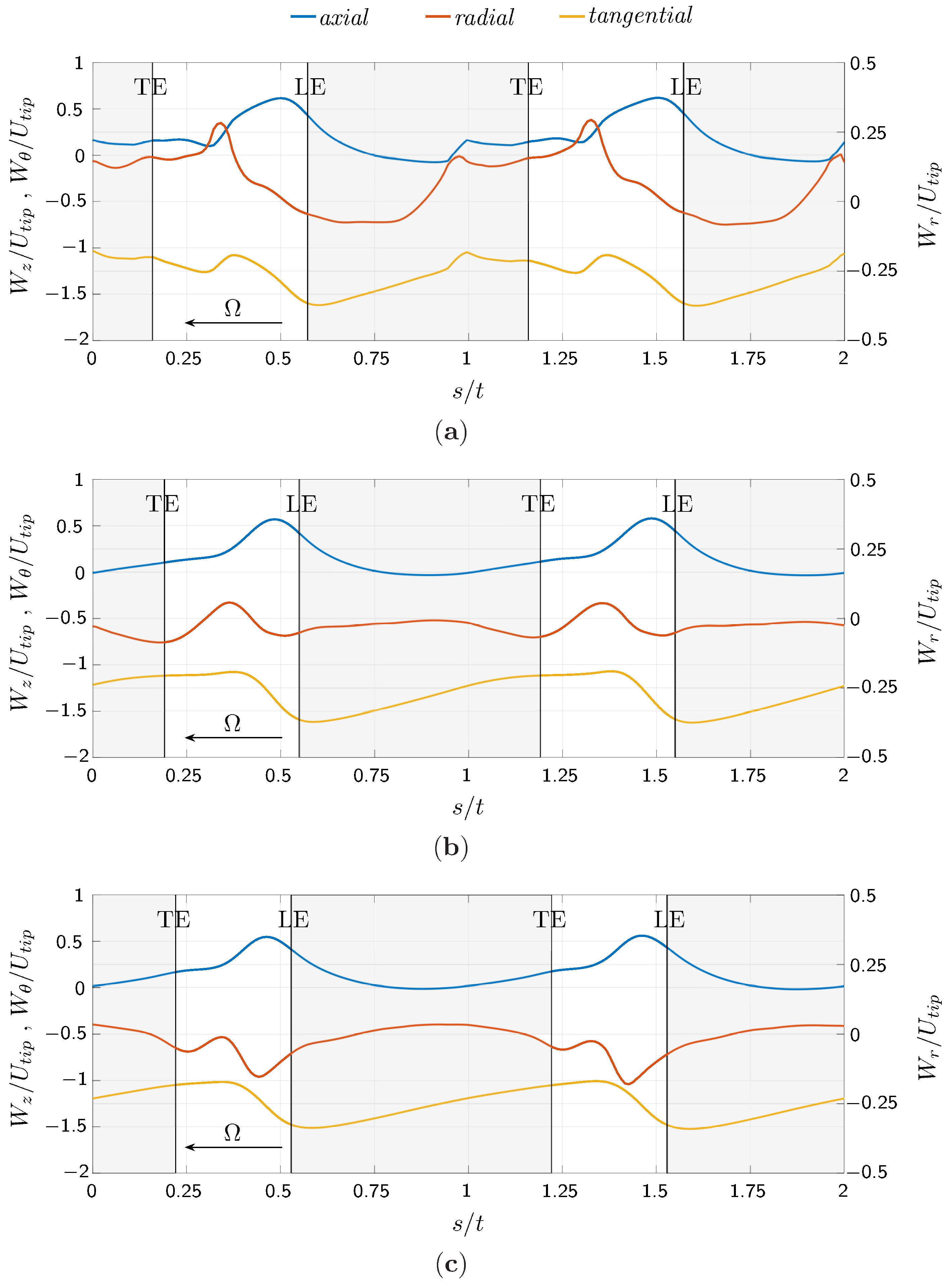
4.2. Flow Structures at the Turbine’s Outlet

A complete visualization of the relative flow field downstream of the rotor is shown in Figure 5, in the form of contour plots of the relative velocity components. Velocity maps were built based on pitchwise distributions with the superposition of blades outline to aid the interpretation.
The maps give an overall representation of the flow field in a blade vane that is strongly related to the uncommon 90-degree stagger of the Wells turbine’s blade. In fact, the maps in Figure 5 represent the flow that develops on the blades suction side and the typical wake region downstream the trailing edge (TE) cannot be identified. Moreover, the interaction between the wake detached from a TE and the flow on the leading edge (LE) of the adjacent blade complicates the flow structure interpretation.
It can be observed how the leakage flow interacts with the clean flow in proximity of the blade trailing edge at higher radii, thus resulting in a distortion of the flow field with respect to all the velocity components. Another peculiar feature of the flow is the near zero axial velocity components in the region close to the suction side of the blade, which is present at this high flow coefficient, even if a complete stall has not yet been reached. As a consequence, the flow is forced through a narrow circumferential area, recognizable by the higher values of  W z . The presence of a vortical structure at higher radii is more easily identifiable referring to the radial velocity component in Figure 5c, which shows negative values in the proximity of the leading edge, probably due to the blockage effect of the blade. Moving towards the trailing edge, the tip vortex forms and detaches from the blade, as can be seen from the positive radial velocity values in a zone near the tip. In the proximity of the trailing edge, the vortex is strengthened and affects a wider area, around 30% of the blade height.
Near the hub, the passage vortex formed in the pressure side is forced to pass in the reduced circumferential zone with higher axial velocity. This can be deduced by the rapid changes in radial velocity from strongly positive to strongly negative values that can be observed in this region. This vortex also influences the flow field near the suction side of the blade, as the effects of the counter vortex are not clearly visible.
In a more quantitative representation, Figure 6 shows the relative velocity components, i.e., in the axial ( W z ), radial ( W r ) and tangential direction ( W θ ), at different circumferential positions, non-dimensionalized with respect to the blade pitch t, and for three different radial positions. The TE and leading edge LE locations have also been reported in order to facilitate reading of the graphs, as well as the direction of rotation.
The axial velocity presents higher values in the region between two adjacent blades, with a peak in the proximity of the LE, along the whole blade span as also highlighted in Figure 6a. This trend, which is not common for typical axial turbine configurations, is due to the 90-degree stagger of the blades: the mass flow is forced to pass through the space between two adjacent blades, thus producing a jet close to the LE, which energizes the wake detached from the TE of the previous blade. Moving from the hub to the tip region, i.e., from Figure 6a–c, higher values of  W z  are detected in the jet region while the latter tends to occupy a larger portion of the free space between two blades. This is due to the reduced solidity of the rotor, that allows much more mass flow to pass. Most of the pitchwise axial velocity distribution is affected by the flow along the blade suction side where low values, close to zero, can be observed. Near the tip region, values of negative axial velocity are observed due to the presence of the leakage vortex, which takes up a wide portion of the blade vane.
The radial velocity component,  W r , shows lower values and limited gradients in the hub and midspan regions, with negative values in the region between two blades, in particular at low radii as shown in Figure 6c. Both gradients and absolute values of  W r  are larger in the tip region where the presence of the leakage flow strongly affects the three-dimensional behavior of the flow field with a significative radial component.
The tangential velocity component,  W θ , is always negative, as expected, and its module smoothly decreases from the leading edge to the trailing edge, with higher gradients close to the leading edge.

4.3. Radial Distribution of Tangentially Averaged Flow

A mass-weighted averaging of the relative velocity components was performed in the circumferential direction along a blade pitch, in order to compute their mean radial distributions, as shown in Figure 7.
The radial distribution of the relative axial velocity  W z  is characterized by an almost constant value for  r *  = 10–75%. The tip region shows larger (positive) values of  W z  due to the leakage flow that affects at least 20% of the blade span. Lower wall effects can be observed near the hub region. These effects can be better appreciated from the radial component  W r  that is affected by larger gradients in the tip region than near the hub. A negative value of  W r  is observed from the hub to the midspan where the flow is moving from higher to lower radii, driven by the higher losses in the hub region. This trend is overturned in the upper part of the blade height, in proximity of 60% of the blade span. This positive trend of the radial component can be justified considering the leakage flow at the tip, which considerably reduces the height of the blade channel where the clean flow can pass through, thus introducing a highly three-dimensional behavior of the flow field.
Based on averaged velocities distributions of Figure 4 and Figure 7, inlet and exit velocity triangles can be drawn as shown in Figure 8 at three spanwise locations.
This representation helps to highlight a few interesting characteristics: (a) The presence of the inlet swirl, (b) non-uniform distribution of mass flow and (c) radial variation of the Euler work (associated with difference in tangential velocity components between the rotor inlet and outlet).

4.4. Rotor Performance

Local performance has been evaluated based on the reconstructed flow field at the turbine’s outlet, in terms of the non-dimensional work coefficient  Λ  which is evaluated as the ratio between the Euler work and the square of the blade tip velocity:
Λ = l U t i p 2
The work coefficient is reported in Figure 9 in the form of a contour map in two adjacent blade vanes.
The contour plot demonstrates that the region with the highest exchanged work is located near the leading edge and around 40–80% of the blade span. This value tends to reduce to very low values, but still positive, moving from the leading edge to the trailing edge. Then, in the regions characterized by the presence of the tip leakage flow, i.e., at high radii and near the trailing edge, the work coefficient assumes very low, close to zero, values, thus emphasizing the presence of high losses. The resulting output work from the turbine is reduced by the presence of this wide region of losses; therefore, this local characterization can aid in finding geometry modifications of the rotor in order to improve its efficiency. In order to better quantify the effect of the tip leakage vortex on the output work, Figure 10 shows the work coefficient averaged on a blade pitch along the blade span.
This representation makes it more evident that the detrimental effect of the leakage vortex in reducing performance takes up a relevant portion of the blade height. It also appears clear that the work coefficient distribution follows the same trend as the tangential velocity of Figure 7c.

5. Conclusions

A detailed experimental investigation of the local flow field inside a Wells rotor is presented herein. The high-frequency response and low intrusiveness of the HWA probe has allowed the flow reconstruction in a blade pitch and along its span as never done before for a Wells turbine. The main results of this investigation can be summarized as follows:
  • The tip leakage flow has been shown to play a significant role in modifying the clean flow distribution downstream of the rotor; its interaction with the flow at the suction side produces a vortex in the tip region that encompasses a relevant portion of the blade channel, due to the relatively high hub-to-tip ratio of the tested rotor.
  • The variable rotor solidity along the blade span contributes to distortion of the flow field at higher radii, as the flow moves to higher radii where the space in between the blades is larger;
  • The regions affected by the presence of the leakage vortex result in negative values of the exchanged work, thus the overall output work from the rotor is sensibly reduced.
The present experimental results could help define the rotor geometry modifications that can improve the performance of a Wells turbine. Moreover, these findings may provide highly useful data for the validation of numerical simulations.

Author Contributions

Conceptualization, P.P.; methodology, F.L. and P.P.; software, F.L. and P.P.; formal analysis, F.L. and P.P.; investigation, F.L. and P.P.; data curation, F.L. and P.P.; writing—original draft preparation, F.L.; writing—review and editing, F.L., T.G., F.C. and P.P.; visualization, F.L., T.G., F.C. and P.P.; supervision, P.P.; project administration, P.P. All authors have read and agreed to the published version of the manuscript.

Funding

This study was carried out within the “e.INS - Ecosystem of Innovation for Next Generation Sardinia” funded by the Italian Ministry of University and Research under the Next-Generation EU Programme (National Recovery and Resilience Plan—PNRR, M4C2, INVESTMENT 1.5—DD 1056 of 23/06/202, ECS00000038). This manuscript reflects only the authors’ views and opinions, neither the European Union nor the European Commission can be considered responsible for them.

Institutional Review Board Statement

Not applicable.

Informed Consent Statement

Not applicable.

Data Availability Statement

The data presented in this study are available on request from the corresponding author.

Conflicts of Interest

The authors declare no conflict of interest.

Nomenclature

Acronyms
HWAhot-wire anemometer
OWCOscillating Water Column
WECWave Energy Converter
Dimensional properties
Cabsolute flow velocity
cblade chord
Drotor diameter
fturbine rotational frequency
l = U ( C θ , 1 C θ , 2 )  Euler work
Ω angular velocity
scircumferential position
tblade pitch
T w piston period
Uperipheral rotor speed
V p piston velocity
Wrelative flow velocity
X p piston position
znumber of blades
Non-dimensional properties
Λ work coefficient
ν hub-to-tip ratio
ϕ flow coefficient
p w * pressure drop coefficient
ReReynolds’ number
r * = ( r r h u b ) / ( r t i p r h u b )  non-dimensional turbine radius
T * torque coefficient
T u turbulence intensity
Subscripts and superscripts
1turbine’s inlet
2turbine’s outlet
hubturbine hub
LEleading edge
rradial direction
refreference value
TEtrailing edge
θ tangential direction
tipturbine tip
zaxial direction

References

  1. Pelc, R.; Fujita, R. Renewable energy from the ocean. Mar. Policy 2002, 26, 471–479. [Google Scholar] [CrossRef]
  2. Aderinto, T.; Li, H. Ocean Wave Energy Converters: Status and challenges. Energies 2018, 11, 1250. [Google Scholar] [CrossRef] [Green Version]
  3. Falcão, A.F.O. Wave energy utilization: A review of the technologies. Renew. Sustain. Energy Rev. 2010, 14, 899–918. [Google Scholar] [CrossRef]
  4. Wells, A.A. Fluid Driven Rotary Transducer. BR Patent 1595700, 13 November 1976. [Google Scholar]
  5. Raghunathan, S.; Tan, C.P.; Ombaka, O.O. Performance of the Wells self-rectifying air turbine. Aeronaut. J. 1985, 89, 369–379. [Google Scholar] [CrossRef]
  6. Curran, R.; Gato, L.M.C. The energy conversion performance of several types of Wells turbine designs. Proc. Inst. Mech. Eng. Part A J. Power Energy 1997, 211, 133–145. [Google Scholar] [CrossRef]
  7. Paderi, M.; Puddu, P. Experimental investigation in a Wells turbine under bi-directional flow. Renew. Energy 2013, 57, 570–576. [Google Scholar] [CrossRef]
  8. Torresi, M.; Stefanizzi, M.; Gurnari, L.; Filianoti, P.; Camporeale, S. Experimental Characterization of the Unsteady Performance Behavior of a Wells Turbine Operating at High Flow Rate Coefficients. In Proceedings of the 75th Italian National Congress ATI, Rome, Italy, 15–16 September 2020; Volume 197, p. 08009. [Google Scholar] [CrossRef]
  9. Licheri, F.; Ghisu, T.; Cambuli, F.; Puddu, P. Detailed investigation of the local flow-field in a Wells turbine coupled to an OWC simulator. Renew. Energy 2022, 197, 583–593. [Google Scholar] [CrossRef]
  10. Alves, J.S.; Gato, L.M.C.; Falcão, A.F.O.; Henriques, J.C.C. Experimental investigation on performance improvement by mid-plane guide-vanes in a biplane rotor Wells turbine for wave energy conversion. Renew. Sustain. Energy Rev. 2021, 150, 111497. [Google Scholar] [CrossRef]
  11. Licheri, F.; Ghisu, T.; Cambuli, F.; Puddu, P. Experimental Analysis of the Three Dimensional Flow in a Wells Turbine Rotor. In Proceedings of the 15th European Turbomachinery Conference, Paper n. ETC2023-148, Budapest, Hungary, 24–28 April 2023; Available online: https://www.euroturbo.eu/publications/conference-proceedings-repository/ (accessed on 21 May 2023).
  12. Puddu, P.; Paderi, M.; Manca, C. Aerodynamic characterization of a Wells turbine under bi-directional airflow. In Proceedings of the 68th Italian National Congress ATI, Bologna, Italy, 11–13 September 2013; Volume 45, pp. 278–287. [Google Scholar] [CrossRef]
  13. Fujita, H.; Kovasznay, L.S.G. Measurement of Reynolds Stress by a Single Rotated Hot Wire Anemometer. Rev. Sci. Instruments 1968, 39, 1351–1355. [Google Scholar] [CrossRef]
  14. He, X. Measurement with a Rotating Slant-Sensor Probe; Dantec Information; Tonsbakken 16–18 DK-2740 Skovlunde Denmark; DANTEC Elektronik: Copenhagen, Denmark, 1988; pp. 9–12. [Google Scholar]
  15. Puddu, P. Tip leakage flow characteristics downstream of an axial flow fan. In Proceedings of the ASME 1996 International Gas Turbine and Aeroengine Congress and Exhibition, Birmingham, UK, 10–13 June 1996; Volume 1. Turbomachinery. [Google Scholar] [CrossRef]
  16. Jørgensen, F.E. Directional Sensitivity of Wire and Fiber Film Probes; Tech. Rep. DISA Information, N. 11; DISA Elektronik A/S, DK-2740 Skovlunde Denmark; DANTEC Elektronik: Copenhagen, Denmark, 1971; pp. 11–31. [Google Scholar]
  17. Lòpez Penã, F.; Arts, T. The rotating slanted hot wire anemometer in practical use. In Proceedings of the 2nd International Conference on Experimental Fluid Mechanics (ICEFM ‘94), Torino, Italy, 4–8 July 1994; pp. 388–399. [Google Scholar]
  18. King, L.V.; Barnes, H.T. XII. On the convection of heat from small cylinders in a stream of fluid: Determination of the convection constants of small platinum wires with applications to hot-wire anemometry. Philos. Trans. R. Soc. Lond. Ser. A Contain. Pap. Math. Phys. Character 1914, 214, 373–432. [Google Scholar] [CrossRef] [Green Version]
  19. Erriu, N.; Mandas, N.; Puddu, P. Alcune considerazioni sulla valutazione dell’incertezza nelle misure con anemometro a filo caldo. In Proceedings of the VII MIS-MAC Conference, Quartu S. Elena, Italy, 21 April 2001. [Google Scholar]
  20. Nurzia, F.; Puddu, P. Experimental investigation of secondary flows in a low hub-tip ratio fan. In Proceedings of the ASME 1994 International Gas Turbine and Aeroengine Congress and Exposition, The Hague, The Netherlands, 13–16 June 1994; Volume 1. Turbomachinery. [Google Scholar] [CrossRef]
  21. Licheri, F.; Puddu, P.; Cambuli, F.; Ghisu, T. Experimental Investigation on a Speed Controlled Wells Turbine for Wave Energy Conversion. In Proceedings of the ASME 2022 41st International Conference on Ocean, Offshore and Arctic Engineering, Hamburg, Germany, 5–10 June 2022; Volume 8. Ocean Renewable Energy. [Google Scholar] [CrossRef]
  22. Licheri, F.; Cambuli, F.; Puddu, P.; Ghisu, T. A comparison of different approaches to estimate the efficiency of Wells turbines. J. Fluids Eng. 2021, 143, 051205. [Google Scholar] [CrossRef]
Figure 1. Experimental setup scheme and test section.
Ijtpp 08 00021 g001
Figure 2. Piston motion characteristics during a test.
Ijtpp 08 00021 g002
Figure 3. Non-dimensional turbine’s performance under stationary flow. (a) Torque coefficient. (b) Pressure coefficient.
Ijtpp 08 00021 g003
Figure 4. Mass-averaged flow characteristics upstream the rotor. (a) Absolute velocity components. (b) Turbulence intensity.
Ijtpp 08 00021 g004
Figure 5. Contour plots of the relative velocity components downstream the rotor in two adjacent blade passages. (a) Axial velocity. (b) Tangential velocity. (c) Radial velocity.
Ijtpp 08 00021 g005
Figure 6. Circumferential distribution of the relative velocity components downstream of the rotor at (a) 80% of span, (b) 50% of span and (c) 20% of span.
Ijtpp 08 00021 g006
Figure 7. Relative velocity components at the turbine’s outlet averaged on a blade pitch. (a) Axial component. (b) Radial component. (c) Tangential component.
Ijtpp 08 00021 g007
Figure 8. Velocity triangles at the rotor inlet and outlet sections.
Ijtpp 08 00021 g008
Figure 9. Contour plots of the work coefficient in two adjacent blade passages.
Ijtpp 08 00021 g009
Figure 10. Work coefficient averaged on a blade pitch.
Ijtpp 08 00021 g010
Table 1. Geometric parameters of the Wells turbine.
rotor tip dia,  D t i p 250 mm
rotor hub dia,  D h u b 190 mm
tip clearance1 mm
chord length, c36 mm
number of blades, z12
airfoil profileNACA 0015
solidity0.625
sweep ratio0.5 (18/36)
hub-to-tip ratio,  ν 0.76
Table 2. Settings of experimental tests.
piston stroke amplitude≈850 mm
piston period,  T w 7 s
turbine rotational frequency, f65 Hz
flow coefficient of the mean flow
at rotor tip radius,  ϕ = C z / ( π f D t i p )
≈0.195
Reynolds’ number based on blade chord
and on the mean outlet relative velocity
1.3 × 10 5
Disclaimer/Publisher’s Note: The statements, opinions and data contained in all publications are solely those of the individual author(s) and contributor(s) and not of MDPI and/or the editor(s). MDPI and/or the editor(s) disclaim responsibility for any injury to people or property resulting from any ideas, methods, instructions or products referred to in the content.

