
Potential of Static Pressure Recovery of Rotor-Only Low-Pressure Axial Fans †
Institute of Jet Propulsion and Turbomachinery, Technische Universität Braunschweig, Hermann-Blenk-Str. 37, 38108 Braunschweig, Germany
*
Author to whom correspondence should be addressed.
†
This manuscript is an extended version of the ETC2023-157 meeting paper published in the Proceedings of the 15th European Turbomachinery Conference, Budapest, Hungary, 24–28 April 2023.
Int. J. Turbomach. Propuls. Power 2023, 8(3), 33; https://doi.org/10.3390/ijtpp8030033
Submission received: 22 May 2023
/
Revised: 21 August 2023
/
Accepted: 4 September 2023
/
Published: 8 September 2023
Abstract
:Typically installed in a rotor-only configuration, low-pressure axial fans discharge directly into a free atmosphere and the discharge shows a strong swirl component. Since such designs, without guide vanes, cannot convert the dynamic pressure in the swirl component back into static pressure, the dynamic pressure is usually considered a loss. However, the radial equilibrium shows that a significant part of the kinetic energy contained in this swirl component is recovered as static pressure in the free atmosphere. This additional pressure increase has been sparsely researched. A comparison between two configurations with and without outlet guide vanes allows for the formulation of an evaluation criterion of the rotor-only configuration. Utilizing this evaluation criterion, the investigation of velocity profiles corresponding to generic rotor designs shows promise in terms of pressure recovery for new designs.
1. Introduction
In a broad range of applications, low-pressure axial fans are designed to achieve large volumetric flow rates while maintaining small pressure ratios. Typically, due to cost and space constraints, these fans are installed in a rotor-only configuration, discharging a swirling jet flow into a free atmosphere. Such a design, without outlet guide vanes, cannot convert the dynamic pressure of the swirl component back into static pressure. This reduces the static pressure at the outlet of the machines. However, simple considerations show that in this free discharge, a static pressure recovery takes place. Indeed, a significant portion of the total-to-static pressure increase from low-pressure axial fans can take place in the discharge; thus, a thorough evaluation of this pressure recovery with regards to fan design is necessary.
Available experimental investigations on the achievable static pressure recovery downstream of rotor-only axial fans are first found in [1]. Here, a free vortex design with a hub-to-tip ratio of is used. For this machine, the measured static pressure recovery in the free discharge corresponds to an increase in efficiency of 4–7%. It is quite interesting that the potential of efficiency increase via downstream guide vanes for such machines is given in [2] as 4–12%, which is within similar orders of magnitude.
In [3], a study on maximizing the efficiency of axial fans was performed. The authors used a CFD method trained by neural networks from [4], which was coupled with an evolutionary optimization algorithm. The main result of their numerical study was a maximum total-to-static efficiency of 68%, taking into account certain geometrical design criteria such as fixed sweep angle or axial design space. In contrast, the typical achievable total-to-static efficiencies of industrial machines tend to be 50–55%.
In the remaining relevant literature, no focus was set on the integral quantity of pressure recovery. Instead the flow field of the discharge itself has been investigated in great detail.
Experimental studies of the flow field downstream of rotor-only axial fans are performed in [5]. Here, optical measurements of a fan discharging into a pipe show that a strongly heterogeneous and non-uniform turbulent outflow is formed, which is characterized by high turbulence intensities, especially in the forming vortex core, revealing the complexity of fan discharge flows.
In [6], numerical investigations of the near downstream flow of a rotor-only axial fan at low flow rates were performed. The studies show that the downstream flow in the near-field, which has a direct influence on the pressure recovery, depends significantly on the flow rate. The latter, in turn, has a direct influence on the flow phenomena within the blade passage, which varies depending on the design method.
Considering the available studies, the behavior of the static pressure recovery remains an open question. In particular, two questions are investigated in this work, which corresponds to our paper published in the 15th European Turbomachinery Conference [7]:
- What is the maximum effect that can be achieved via optimum static pressure recovery and how can it be evaluated?
- To what extent can the static pressure recovery be influenced by the geometric features of the machine and the vortex design?
2. Static Pressure Recovery of Rotor-Only Low-Pressure Axial Fans
2.1. Assumptions and General Mechanism
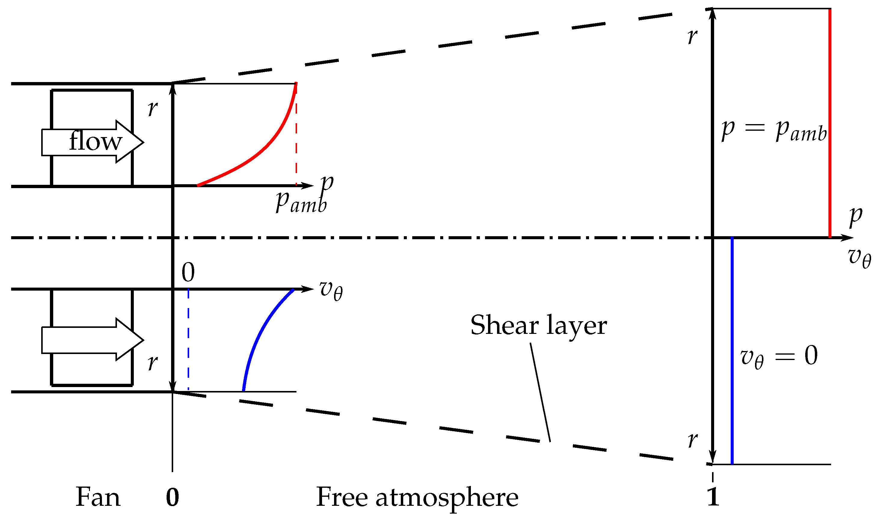
Figure 1 shows a rotor-only axial fan configuration discharging into a free atmosphere with the qualitative radial profiles of the circumferential velocity (blue) and the static pressure p (red). As explained in Section 1, the flow field generally is strongly heterogeneous and non-uniform. Consequently, several assumptions are necessary for the derivations in this paper:
- At location 0, immediately downstream of the trailing edge, the flow is axisymmetric, inviscid, and has no radial velocity components and no meridional curvature of the exit streamlines;
- The ambient pressure is imprinted on the shear layer between the fan discharge and the free atmosphere (i.e., at );
- Location 1 is positioned sufficiently far downstream of location 0, such that the circumferential velocity component of the discharge has entirely vanished via momentum exchange (i.e., mixing) with the environment;
- The free atmosphere is sufficiently large, such that walls and other obstructions are not influencing the free exhaust;
- The flow is assumed to be steady and incompressible.
Under assumptions 1 and 2, the radial distributions of the static pressure p and the circumferential velocity component are coupled through the radial equilibrium:
Considering location 0 of Figure 1, the discharge shows a non-zero radial distribution of the circumferential velocity. Evaluating Equation (1) with such a distribution yields a monotonically increasing static pressure distribution with as the maximum value at the shear layer. Consequently, the average static pressure at location 0 is below ambient pressure.
Further downstream at location 1, the circumferential velocity has vanished under assumption 3. Considering Equation (1) again, this results in the static pressure being constant over the radius, and, subsequently, the average pressure at location 1 is equal to the ambient pressure. Following this argumentation, the average static pressure must have increased from location 0 to location 1. In fact, from location 0 to location 1, a considerable amount of the kinetic energy contained in the fan discharge is converted into potential energy in form of a static pressure increase. Therefore, the free atmosphere acts as an outlet guide vane.
2.2. Evaluation Criterion of the Static Pressure Recovery
To investigate the potential of static pressure recovery in the free atmosphere, it has to be properly evaluated. A reasonable evaluation criterion should be able to compare different fan designs regardless of their vortex design, operating point, and geometric features.
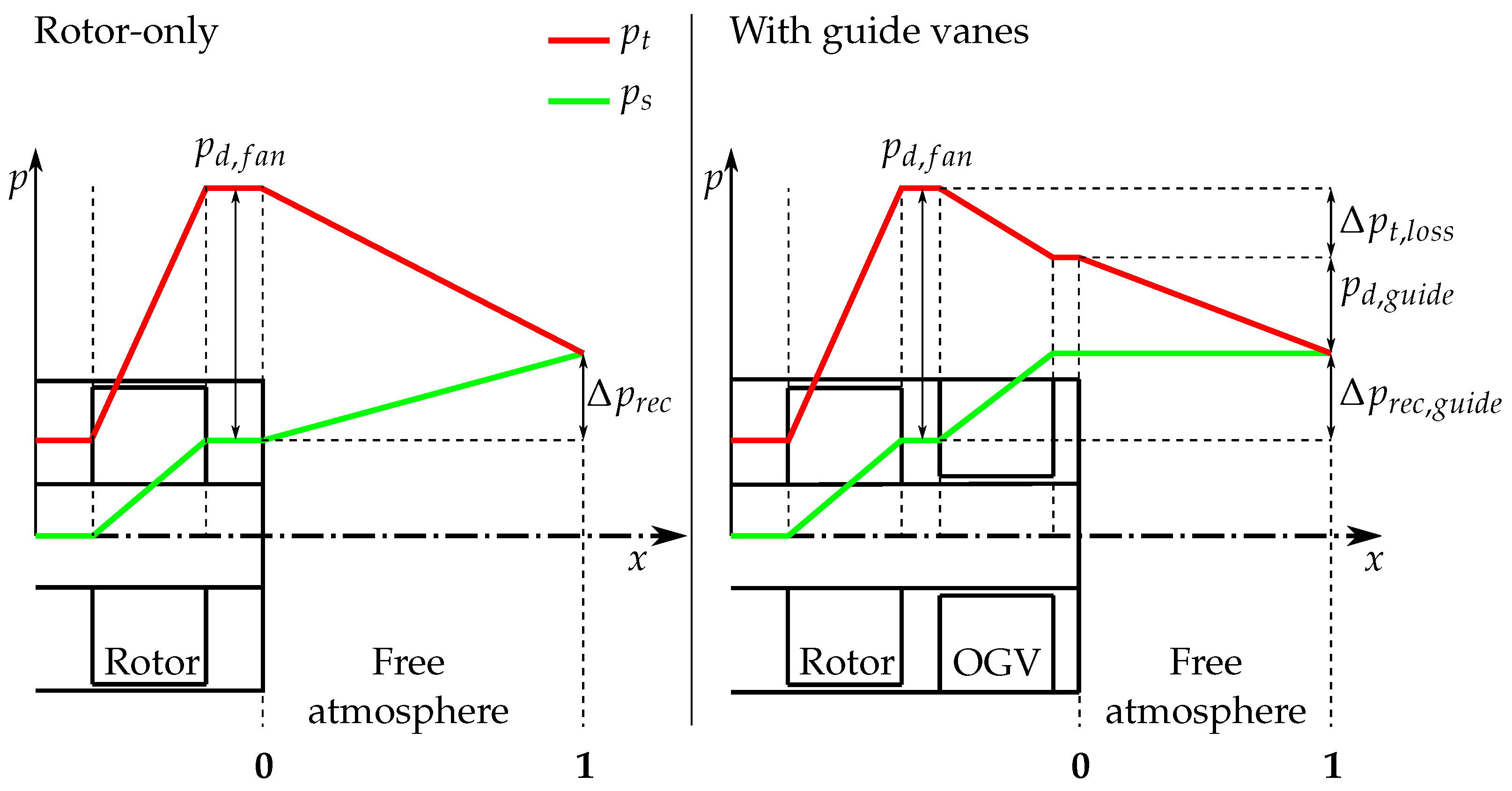
To derive such an evaluation criterion, the rotor-only configuration of Figure 1 is compared to a configuration with outlet guide vanes, schematically visualized in Figure 2. The axial progressions of the average total and static pressure from the inlet to location 1 are shown in red and green, respectively. These curves are highly idealized in the sense that losses in the ducts up- and downstream of the rotor and stator are neglected.
In the rotor-only configuration (left side of Figure 2), the fan increases the average static and total pressure from inflow conditions resulting in the dynamic pressure in the fan discharge . In the free atmosphere downstream of the fan, the static pressure increases by and the total pressure decreases until, eventually, the dynamic pressure is equal to zero.
The right side of Figure 2 shows a configuration with outlet guide vanes downstream of the fan. In this configuration, the fan is assumed to be equivalent to the rotor-only case, achieving the same pressure increase and, consequently, the same dynamic pressure . In contrast to the rotor-only case, the circumferential velocity component of the discharge is decelerated in the outlet guide vanes and, accordingly, the static pressure is increased by . The discharge of the guides vanes has an average dynamic pressure of . Furthermore, the outlet guide vanes introduce a total pressure loss to the flow. The discharge of the guide vanes into the free atmosphere does not lead to a static pressure recovery, since it has, by its idealized definition, no circumferential velocity component and, consequently, the mechanism of static pressure increase described earlier does not apply. Analogous to the rotor-only case, the residue dynamic pressure in the free atmosphere will eventually tend to zero at location 1 by dissipation.
From the right side of Figure 2, it is apparent that in the case of the installed outlet guide vanes, the dynamic pressure of the fan is split exactly into the total pressure loss of the guide vanes , the dynamic pressure downstream of the outlet guide vanes , and the static pressure increase the guide vanes , as in
An evaluation criterion can be derived from this, when requiring the pressure increase of the guide vanes to be equal to the static pressure recovery of the rotor-only configuration:
Adapting this into Equation (2) and isolating the total pressure loss of the guide vanes yields
More precisely, outlet guide vanes that induce a total pressure loss of , as computed by Equation (4) to the system, achieve exactly the same amount of static pressure increase as a corresponding rotor-only configuration does in the free atmosphere. To increase comparability between different designs, this total pressure loss can be formulated into a total pressure loss coefficient leading to the desired evaluation criterion of the static pressure recovery by
Replacing the total pressure loss of the guide vanes by Equation (4) eventually yields
When comparing different fans in a rotor-only configuration and computing for each design, fan designs with low values of achieve a better static pressure recovery than design with high values of . From a different perspective, fan designs in a rotor-only configuration, for which a certain value of is determined, achieve the same total-to-static pressure increase as configurations with guide vanes, where the guide vanes have an total pressure loss coefficient of exactly .
2.3. Modeling of Static Pressure Recovery
To utilize as an evaluation criterion from a design point of view, it is necessary to be able to assess it from fan design parameters directly. Central parameters of fan design are the radial profiles of the axial () and circumferential () velocity downstream of the fan, which are defined by the vortex design. With knowledge of the velocity profiles, all pressures entering can be computed as described in the following.
The local dynamic pressure in the discharge of the fan is a function of local velocity magnitude and thus a function of and only. Mass flow weighted averaging of the dynamic pressure eventually yields
To compute , the discharge of the configuration with guide vanes is assumed to be constant over radius and purely axial. Consequently, the dynamic pressure downstream of the outlet guide vanes can be simplified to a function of the volume flow and the geometry:
To compute the total pressure loss coefficient through Equation (6), the pressure recovery in the free atmosphere of the rotor-only configuration is still unknown and has to be estimated. Generally, this pressure recovery is defined as the difference between the average pressure at location 1 and location 0:
As described in Section 2.1, the average pressure at location 1 is equal to the ambient pressure. To estimate the average static pressure at location 0, Equation (1) is recapped, linking the static pressure to the circumferential velocity. Since is a static pressure, the average pressure is derived as an area weighted average. Setting the area weighted average of computed by Equation (1) into Equation (9), the static pressure recovery in the free atmosphere is
Eventually, with all corresponding pressures set into Equation (6), is given as a function of and by
3. Methodology
3.1. Idealized Reference Design
To explore a design space defined later in this work towards the potential of , an idealized reference design is generated as a starting point. To compute , only the downstream velocity profiles and the hub and tip radius are needed. Consequently, no real fan designs themselves but rather only the resulting downstream velocity profiles are considered in this work, implying the corresponding airfoil design. To keep these downstream velocity profiles as simple as possible, the flow is highly idealized in the sense that boundary layers and secondary flows are neglected. The idealized reference design is then assumed to be a free vortex design, which is characterized by a downstream circumferential velocity proportional to . Considering the radial equilibrium, this yields a constant axial velocity over the radius:
The overall level of the profiles (or the value of the constants and , respectively) is adjusted to match the operating point. The operating point of the reference design is defined in terms of flow coefficient and total-to-total work coefficient by
The total-to-total pressure increase is derived from the mass averaged Euler-work and is thus a function of the velocity profiles. The inflow circumferential velocity is assumed to be zero. The blade tip speed is given by the tip radius and the rotational speed. Additionally, a hub-to-tip ratio is given to assess the hub radius. Table 1 summarizes the operating point and the geometric parameters, which are set to the values of conventional low-pressure axial fans. The investigated hub-to-tip ratios of 0.3 and 0.5 respresent the lower and upper limits of usual designs.
3.2. Two-Dimensional Design Space
With the downstream velocity profiles of the idealized reference design, a two-dimensional design space can be spanned open by individually varying the axial and circumferential velocity profiles, although, as discussed later, this leads to non-physical design. This variation of the velocity profiles is achieved by adding the linear shifting functions and .
Since the shifting functions and are linear, they are fully defined by their radial gradients and and constants and . Positive values of and generate velocity profiles shifted to the casing, and negative values generate velocity profiles shifted to the hub, respectively. During the shifting process of the velocity profiles, their overall level is adjusted by and , respectively, to ensure that the operating point in terms of and is constant for all generated profiles. Adding the linear shifting functions to the velocity profiles of the reference design in Equation (12), the shifted downstream velocity profiles are given by
Consequently, and are the parameters spanning a two-dimensional design space for the variation of the velocity profiles, whereas and are kept constant to the values of the reference-free vortex design. These two parameters are varied independently. Obviously for axial fans, such an independent variation is impossible to achieve. In fact, Equation (14) is analogue to a more general vortex design, where the term represents a free vortex and the term denotes the solid vortex. When varying the solid vortex part by varying , each resulting circumferential velocity profile is coupled to a specific axial velocity profile through the isentropic simple radial equilibrium. The resulting axial velocity profile, in turn, can be approximated by a linear profile and subsequently linked to a certain value of . This yields a single line of theoretically realizable velocity profiles of axial fans in the two-dimensional design space of and , which will be discussed later in this work. Theoretically, deviations from this line might be possible when opening the design space to diagonal or radial machines which induce a considerable streamline curvature, but this will not be considered in this work.
The upper and lower limits of the gradient of the axial shifting function are set such that the axial velocity reaches zero at the casing or hub, respectively, at the boundaries of the design space. The minimal and maximal values of are set equal to the extremes of . Finally, and are normalized by their extremes such that the vectors of the two-dimensional design space and are defined on .
Figure 3 shows samples of the velocity profiles in the design space. The abscissa shows . For velocity profiles on the left side in Figure 3, where is negative, the mass flow is concentrated at the hub, and subsequently, for the profiles on the right side, it is positive and the mass flow is concentrated at the casing. The ordinate shows , resembling the solid vortex part of Equation (14). For velocity profiles on the bottom side in Figure 3, where is negative, the Euler work is increased at the hub, and subsequently, for the profiles on the top side, it is positive and the Euler work is increased towards the casing. The velocity profiles at coordinates (0, 0) in Figure 3 correspond to the reference-free vortex design of Equation (12).
4. Results of the Design Space Exploration
Since every point of the two-dimensional design space represents a set of velocity profiles implying a fan design, can be evaluated for each point, regardless of the fact, that some profiles are non-physical. This yields a contour plot of over and , as shown in Figure 4 for two values of the hub-to-tip ratio of 0.3 (left) and 0.5 (right). In these contours, the black lines represent the points at which the velocity profiles obey the isentropic simple radial equilibrium and which are thus theoretically realizable in axial fan designs. The red crosses mark the optimal, i.e., minimal, value of on these lines.
Considering, first, the whole contour for both hub-to-tip ratios, it is apparent that, generally, the lower value of (left) yields lower (i.e., better) values of . In fact, the global minimal value of is approximately 0.18 for , whereas for , it is 0.31. The best values of for the realizable fan designs (black lines) are 0.35 and 0.53 for and , respectively.
Besides quantitative differences, qualitative observations can be made equally for both hub-to-tip ratios. Generally favorable fan designs in terms of are found in two separate regions, A and B, of the contour plots. Region A at the top center with
corresponds to fan designs with a constant downstream axial velocity and a circumferential velocity shifted towards to the casing. Region B towards the bottom right with
corresponds to fan designs with a downstream axial velocity shifted to the casing and a circumferential velocity shifted towards the hub.
Focusing on the set of downstream velocity profiles that obey the isentropic simple radial equilibrium (black lines in Figure 4), strong variations of can be observed. For the designs with a hub-to-tip ratio of , the optimal value of is 0.35, while adverse designs only reach values around 0.76. In the case of , the optimal value of the realizable designs is 0.53, while other designs fall off to values of 0.84. These harsh differences indeed indicate that it is important to consider the static pressure recovery in the free atmosphere already in the vortex design of the fan. The optimal vortex design in terms of (red crosses in Figure 4) seems to be slightly shifted from a pure free vortex design (coordinates (0, 0)) towards a design with a mix of free vortex and solid vortex.
5. Discussion
The physical interpretation for smaller hub-to-tip ratios yielding favourable values of is a larger annular channel which contains more rotating mass. Consequently, more rotating mass results in higher inertial (i.e., centrifugal) forces, which are initially causing the sub-atmospheric pressure in the fan discharge. Thus, the difference to the ambient pressure in the fan discharge is stronger.
The reason for regions A and B of the design space being favorable become evident when considering Figure 5, which depicts contour plots of the static pressure recovery and the downstream dynamic pressure of the fan . To reiterate Equation (6), both these pressures are the central quantities defining , whereas is constant for a fixed operating point under the assumptions made. Equation (6) shows that high values of and low values of result in good (i.e., low) values of .
When considering, first, the contour of on the left side of Figure 5, favorable regions are at the top left and the bottom right of the design space. In the top left region of the design space, the circumferential velocity is shifted towards the casing. This results in lower pressures at the outer radii and, simultaneously, in higher pressures at the inner radii when compared to the reference design. When area averaging the static pressure over the radius to compute , the lower pressures at the casing outweigh the higher pressures at the hub since they are acting on a larger area. Additionally, in this region, the mass flow is concentrated in regions with the lowest circumferential velocity, i.e., the lowest Euler-work. When requiring the mass-averaged Euler-work to be equal for all velocity profiles, this necessitates a global increase in the circumferential velocity. Eventually, both effects result in higher values of . On the bottom right region of the design space, the circumferential velocity is shifted towards the hub. Here, the effect is opposite to the region on the top left. Although there are higher pressures at the outer radii acting on larger areas, the minimal values of the pressures which arise at the hub compensate for this. Furthermore, in this region, the same global increase in is necessary due to analog reasons, as in the top left region of the design space. Thus, in total, higher values of are achieved in this region. In fact, the free vortex reference design at coordinates (0, 0) achieves quite low values of static pressure recovery when considering the whole design space. In contrast to the contour of , the contour of only shows a singular favorable region of minimal values at the top center of the design space. This is due to both the axial and the circumferential velocities being approximately constant over the radius in this region. Constant velocity profiles result in minimal average dynamic pressure because of the quadratic influence of the velocity on the dynamic pressure. This quadratic influence leads to the fact that non-constant profiles, with their corresponding higher maximum values, result in higher average dynamic pressures. The combination of these different favorable regions of and in the design space eventually result in the favorable regions A and B in the contour of .
6. Conclusions
The general mechanism of the pressure recovery described in Section 2.1 follows directly from a strong circumferential velocity component present in the discharge of the fan, yielding a sub-atmospheric pressure which is vanishing downstream in the free atmosphere. Considering this mechanism, the two questions presented in the introduction are answered in this paper:
The total pressure loss coefficient derived in this work provides a metric by which to evaluate the static pressure recovery in the free atmosphere. The minimal values of are 0.35 and 0.53 for hub-to-tip ratios of and , respectively, when considering the velocity profiles obeying the simple isentropic radial equilibrium. Both values of these total pressure loss coefficients are quite high, especially considering the fact that these are optimal values. Consequently, these results indicate that it is generally possible to design outlet guide vanes for low-pressure axial fans that improve the total-to-static pressure increase when compared to the rotor-only configuration.
The hub-to-tip ratio and the vortex design of the machine significantly impact the static pressure increase. From the two hub-to-tip ratios investigated, the smaller value of generally results in better static pressure recoveries. In fact, for a fixed , the values of vary between 0.53 and 0.84 as a function of the vortex design. For , these reach values between 0.35 and 0.76. So, while generally, outlet guide vanes, which are properly designed in terms of total pressure loss, are beneficial to the total-to-static pressure increase, these results indicate that it is indeed important to consider the static pressure recovery already in the vortex design of the fan when OGVs are not an option due to external constraints. In both cases, the optimal vortex design in terms of static pressure recovery is close to a pure free vortex with the slight addition of a solid vortex part where the exact blending factor depends on the hub-to-tip ratio. With an outlook for real fan design, it is important to point out that for low hub-to-tip ratios, it is increasingly challenging to realize such vortex designs due to the large required flow deflection towards the hub.
Author Contributions
Conceptualization, H.W. and C.B.; methodology, H.W. and C.B.; software, H.W.; validation, H.W.; formal analysis, H.W.; investigation, H.W.; resources, C.B.; data curation, H.W.; writing—original draft preparation, H.W.; writing—review and editing, C.B. and J.F.; visualization, H.W.; supervision, C.B. and J.F.; project administration, J.F.; funding acquisition, J.F. All authors have read and agreed to the published version of the manuscript.
Funding
This research was funded by the Forschungsvereinigung für Luft- und Trocknungstechnik (FLT) (IGF-Nr. 59 EWN). The FLT is part of the German Federation of Industrial Research Associations (AiF), and the projects are financed by the German Federal Ministry for Economic Affairs and Climate Action (BMWK).
Data Availability Statement
The data presented in this study are available on request from the corresponding author.
Conflicts of Interest
The authors declare no conflict of interest.
References
- Marcinowski, H. Optimalprobleme bei Axialventilatoren. Ph.D. Thesis, Technische Hochschule Karlsruhe, Karlsruhe, Germany, 1957. [Google Scholar]
- Marcinowski, H. Druck- und Geschwindigkeitsverteilung hinter dem Laufrad eines Axialventilators. Voith Forsch. Und Konstr. 1957, 2, 5:1–5:17. [Google Scholar]
- Bamberger, K.; Carolus, T. Achievable Total-to-Static Efficiencies of Low-Pressure Axial Fans. In Proceedings of the International Conference on Fan Noise, Fan Technology and Numerical Methods, Lyon, France, 15–17 April 2015. [Google Scholar]
- Bamberger, K.; Carolus, T. Performance Prediction of Axial Fans by CFD-Trained Meta-Models. In Proceedings of the ASME Turbo Expo 2014: Turbine Technical Conference and Exposition, Düsseldorf, Germany, 16–20 June 2014. [Google Scholar]
- Čantrak, Ð.S.; Janković, N. Laser Insight Into the Turbulent Swirl Flow Behind the Axial Flow Fan. In Proceedings of the ASME Turbo Expo 2014: Turbine Technical Conference and Exposition, Düsseldorf, Germany, 16–20 June 2014. [Google Scholar]
- Louw, F.G.; von Backström, T.W.; van der Spuy, S.J. Investigation of the Flow Field in the Vicinity of an Axial Flow Fan during Low Flow Rates. In Proceedings of the ASME Turbo Expo 2014: Turbine Technical Conference and Exposition, Düsseldorf, Germany, 16–20 June 2014. [Google Scholar]
- Witte, H.; Bode, C.; Friedrichs, J. Potential of Static Pressure Recovery of Rotor-Only Low Pressure Axial Fans. In Proceedings of the 15th European Turbomachinery Conference, paper n. ETC2023-157, Budapest, Hungary, 24–28 April 2023; Available online: https://www.euroturbo.eu/publications/conference-proceedings-repository/ (accessed on 6 September 2023).
Figure 1.
Schematic radial distributions of static pressure (red) and circumferential velocity (blue) at two locations in the fan discharge.
Figure 1.
Schematic radial distributions of static pressure (red) and circumferential velocity (blue) at two locations in the fan discharge.

Figure 2.
Comparison of two fan configurations—a rotor-only configuration (left) and a configuration with downstream guide vanes (right)—and their corresponding total (red) and static (green) pressure progressions from the inlet to location 1.
Figure 2.
Comparison of two fan configurations—a rotor-only configuration (left) and a configuration with downstream guide vanes (right)—and their corresponding total (red) and static (green) pressure progressions from the inlet to location 1.

Figure 3.
Velocity profile samples of the design space formed by the normalized gradients of the linear shifting functions. The profiles at (0, 0) correspond to a free vortex design. The resulting velocity profiles at the corners of the designs space (red crosses) are shown for comparison.
Figure 3.
Velocity profile samples of the design space formed by the normalized gradients of the linear shifting functions. The profiles at (0, 0) correspond to a free vortex design. The resulting velocity profiles at the corners of the designs space (red crosses) are shown for comparison.

Figure 4.
Contours of on the design space for a hub-to-tip ratio of 0.3 (left) and 0.5 (right). Velocity profiles obeying the isentropic simple radial equilibrium are shown in black, while the red cross marks the optimal point on this line.
Figure 4.
Contours of on the design space for a hub-to-tip ratio of 0.3 (left) and 0.5 (right). Velocity profiles obeying the isentropic simple radial equilibrium are shown in black, while the red cross marks the optimal point on this line.

Figure 5.
Contour of the static pressure recovery (left) and the dynamic pressure in the fan discharge (right) for . Black lines encircle favorable regions of the design space.
Figure 5.
Contour of the static pressure recovery (left) and the dynamic pressure in the fan discharge (right) for . Black lines encircle favorable regions of the design space.


Table 1.
Operating point and geometric parameters.
| Parameter | RPM | ||||
|---|---|---|---|---|---|
| Value | 0.215 | 0.300 | 0.250 m | 1350 min | 0.3, 0.5 |
Disclaimer/Publisher’s Note: The statements, opinions and data contained in all publications are solely those of the individual author(s) and contributor(s) and not of MDPI and/or the editor(s). MDPI and/or the editor(s) disclaim responsibility for any injury to people or property resulting from any ideas, methods, instructions or products referred to in the content. |
© 2023 by the authors. Licensee MDPI, Basel, Switzerland. This article is an open access article distributed under the terms and conditions of the Creative Commons Attribution (CC BY-NC-ND) license (https://creativecommons.org/licenses/by-nc-nd/4.0/).
Share and Cite
MDPI and ACS Style
Witte, H.; Bode, C.; Friedrichs, J. Potential of Static Pressure Recovery of Rotor-Only Low-Pressure Axial Fans. Int. J. Turbomach. Propuls. Power 2023, 8, 33. https://doi.org/10.3390/ijtpp8030033
AMA Style
Witte H, Bode C, Friedrichs J. Potential of Static Pressure Recovery of Rotor-Only Low-Pressure Axial Fans. International Journal of Turbomachinery, Propulsion and Power. 2023; 8(3):33. https://doi.org/10.3390/ijtpp8030033
Chicago/Turabian StyleWitte, Hauke, Christoph Bode, and Jens Friedrichs. 2023. "Potential of Static Pressure Recovery of Rotor-Only Low-Pressure Axial Fans" International Journal of Turbomachinery, Propulsion and Power 8, no. 3: 33. https://doi.org/10.3390/ijtpp8030033