Article

Transient Resonance Passage of a Mistuned Bladed Disk with and without Underplatform Dampers †

by
Katharina Brinkmann
1,*,
Thomas Hoffmann
1,
Lars Panning-von Scheidt
1 and
Heinrich Stüer
2
1
Institute of Dynamics and Vibration Research, Leibniz University Hannover, 30823 Garbsen, Germany
2
Siemens Energy AG, 45478 Mülheim a. d. Ruhr, Germany
*
Author to whom correspondence should be addressed.
This paper is an extended version of our paper published in the Proceedings of the 15th European Turbomachinery Conference, Budapest, Hungary, 24–28 April 2023.
Int. J. Turbomach. Propuls. Power 2023, 8(4), 38; https://doi.org/10.3390/ijtpp8040038
Submission received: 17 July 2023 / Revised: 15 August 2023 / Accepted: 21 August 2023 / Published: 2 October 2023

Abstract

:
In this work, the vibration response of an academic free-standing turbine blisk is analyzed in regard to transient resonance passages. Measurement data are recorded using strain gauges and tip timing to evaluate the blades first bending mode both linearly and with two different types of underplatform dampers. These results are validated against steady-state responses and show good agreement with each other. To examine the effects of a transient resonance passage, response functions of each blade are evaluated both with and without the underplatform dampers. It is shown that friction damping is able to inhibit any appearance of a transient ring-down. Additionally, a multi-mass oscillator model with frictional contacts is analyzed, which qualitatively exhibits the same dynamics as the measurements. Due to geometric mistuning, all blades exhibit different vibration responses. This can lead to a transient amplitude amplification, which is observed on several blades. Analogously, this phenomenon can be mitigated by friction damping.

1. Introduction

Due to the ongoing need of global power generation for flexibilization, turbine blades are more frequently subject to transient resonance crossings. Typical effects that are expected from this kind of resonance passage such as ring-down and a frequency shift of the maximum amplitude, according to [1], have a significant influence on turbine blade dynamics. Furthermore, this has an impact on both the operational safety, e.g., through a possible high cycle fatigue (HCF), and the evaluation of measurements, especially the calculation of damping values.
Regarding academic turbine blade measurements, commonly, the blade steady-state behaviour is considered (see [2]), but recently, transient measurements have also started to take a prominent part in fundamental research. Several current publications deal with transient measurements of bladed disks either by means of tip timing, strain gauges, both measurement systems or acceleration sensors (see [3,4,5,6]). However, the effect of friction damping on the blade dynamics during a transient resonance passage has rarely been studied experimentally in this context. A time-step simulation performed by [7] shows a distinct reduction in the effects of a transient sweep by means of frictional damping.
Additionally, in the case of these resonance passages, a mode splitting through mistuning can lead to an amplification of the maximum amplitude for individual blades, the so-called TAMS effect (see [5]). Since such an amplification can have major impact on the operational reliability of a turbine blade, this effect as well is subject of recent research (see [8,9]). All of these observations are likewise evaluated in this paper as well as in [10] by using both rotating measurements and simulations.

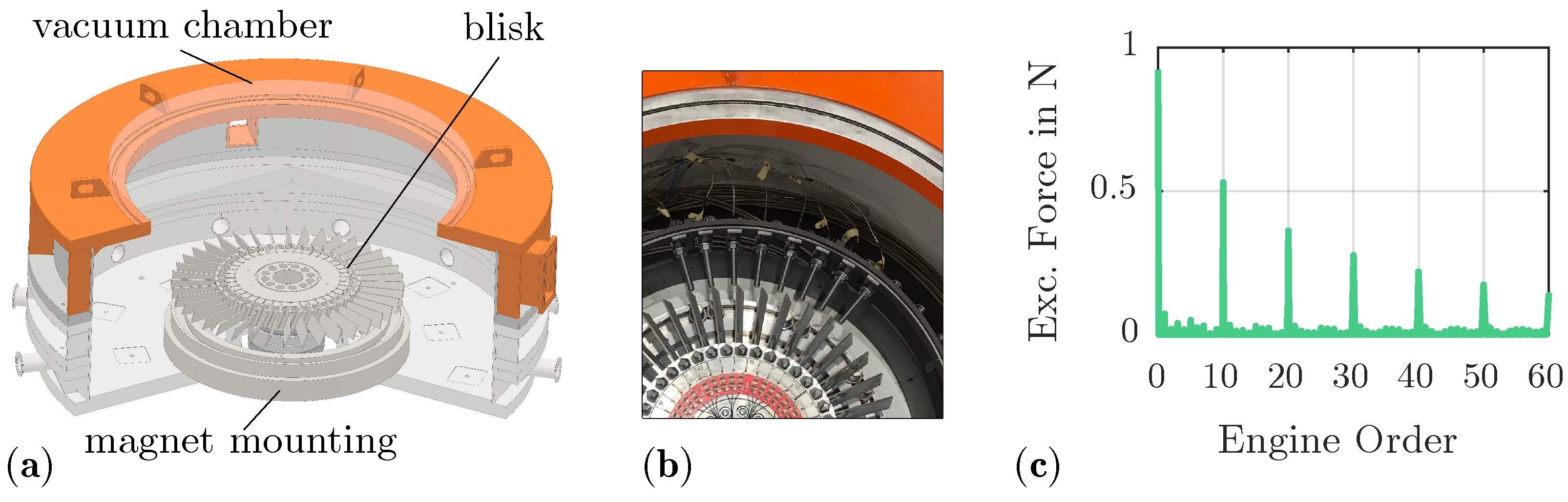
2. Measurement Configuration

For the measurements presented here, a blisk was used with free-standing blades, modelled by means of a simple cantilever beam with the aim of reducing its complexity. The effect of frictional damping on the vibrational behaviour of turbine blades can be adequately reproduced by this kind of test specimen (see [2]).
Figure 1a shows a model of this blisk which was fully assembled with measurement equipment and evaluated during the COOREFlex-turbo joint research program within the frame of AG Turbo (see [2]). The aim in that study was to investigate the effect of friction damping by various underplatform damper (UPD) types on the consequently nonlinear vibrational responses, for which two different geometries were used. In addition to one with a cylindrical cross-section, the asymmetric underplatform damper shown in Figure 1b was also tested. Compared to the first cylindrical type, this one has a flat contact surface on one side and a curved profile on the other.
During these measurements, the turbine blades are excited axially by discrete permanent magnets evenly distributed around the circumference, resulting in a speed-synchronous excitation of the blades. The magnetic force is measured by calibrated Hall sensors, which are attached underneath two of the blades. Since the resulting magnetic field does not have a completely harmonic form, further multiples of the amount of magnets are excited in addition to the static part. This leads to the spectrum of the magnetic excitation force shown in Figure 2c. Here, it can be seen that although each nodal diameter (ND) experiences a certain excitation amplitude, it is relatively small for non-integer multiples of the magnet quantity. Accordingly, it can be assumed that the excitation of the blades along a small speed range is almost of single engine order (EO) type. An additional possible aerodynamic excitation or even ventilation can be disregarded for these measurements since the rotational test rig is equipped with a vacuum chamber (see Figure 2a), in which the blisk is operated.
Due to the previous measurements (see [2]), the strain gauges have already been applied to each blade root, as well as the associated measuring circuit, since the corresponding measurement system was already implemented in the test rig. The circuit board herein includes an amplification of the analogue data as well as a high- and low-pass filter in order to both de-trend the data and reduce the noise. After this, the signal is passed on from the rotating system to the data acquisition structure via a slip ring.
In addition, an AGILIS tip timing system together with the necessary equipment was kindly lent by the Institute of Turbomachinery and Fluid Dynamics during these measurements.
A hermetic fiber optical feedthrough of the test stands vacuum chamber is necessary due to the placement of the entire tip timing probes within its exterior walls. The probe mounting was designed in order to enable the measurement of blisks with different diameters and thicknesses, as well as the detection of various engine order responses. It is possible to move each probe holder axially (ca. 50 mm) and circumferentially ( 360 ), and its length is determined by the blisk diameter. The mounting is attached to the test rig inside the vacuum chamber (see Figure 2b). The necessary precision of the positioning and the orientation of the probes is ensured by additional devices in order to evaluate the first flapwise bending mode (1F) for the considered EOs 10 and 20.
As the strain gauges are attached to almost every blade of the blisk, the individual measurement signals can be assigned to a specific blade number. The tip timing software, on the other hand, can only provide a relative arrangement of the individual blades, so it is necessary to allocate the data of the corresponding measurements before a comparison can be performed (see [11]).

3. Measurement Results

First of all, the necessary assignment is performed by comparing the measurement data from runs without underplatform dampers of both systems against each other. Considering a selected number of blades and speed rates, the allocation results in a qualitatively good agreement of vibration responses gained from each measurement system. Figure 3 shows the resonance peaks of two run-ups with a different sweep rate by both tip timing and the strain gauge of Bade #28, normalized to their respective maximum peak values. The two responses depicted in Figure 3 optically show the same qualitative results for both sweep rates, including the expected ring-down after passing the resonance at approximately 1045 RPM. Due to the design of the motor control, a sweep rate lower than 0.6 RPM s unfortunately is not possible.
Correspondingly, both measurement data, normalized by a respective reference strain and deflection, are used in the following assessment of the blisk dynamics during transient resonance passages, first by comparing the linear blade responses against previous steady-state results from strain gauges and afterwards by evaluating the transient effects and the impact of friction damping on them with frequency response functions, captured by means of tip timing.

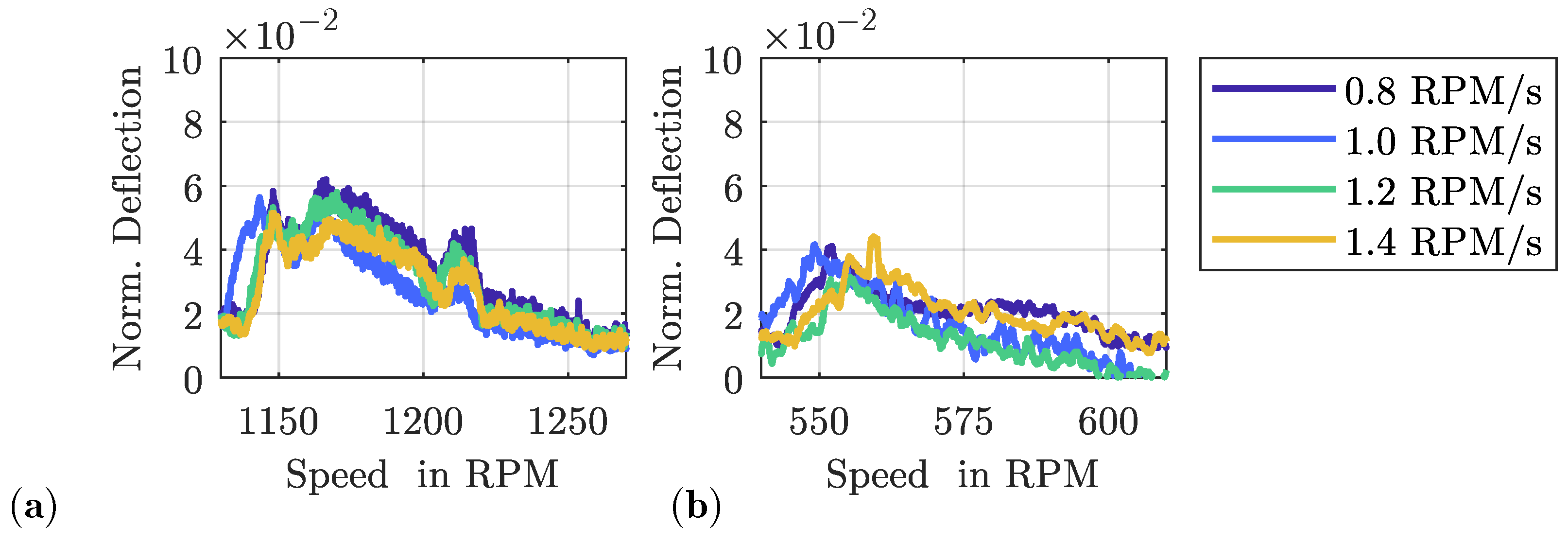
3.1. Transient Effects on Linear Responses

As stated in [1], a transient run-up or coast-down mainly causes a frequency shift of the resonance peak along the sweep direction as well as beating following the resonance peak. This so-called ring-down or beating effect is caused by the linear system’s relatively small structural damping. The blades still oscillate with their only marginally damped natural frequency, while in the case of correspondingly high sweep rates, subsequently, an in- or decreased frequency is already excited. Because of these reasons, the resulting amplitudes of transient sweeps are typically smaller than those of identical steady-state resonance crossings.
Under these conditions, the obtained transient test runs were compared with previous steady-state measurements, in which the speed was increased incrementally, both linearly and with asymmetric underplatform dampers. Accordingly, Figure 4a displays the steady-state measurement results of the free-standing blades without underplatform dampers in comparison to the transient operation in Figure 4b. Each individual response function clearly can be assigned to the respective blade number. However, it is noticeable that the step size of the speed increase for the steady-state measurements is slightly too large, causing the maximum peak amplitude not to be captured accurately for several blades, e.g., for Blade #26.
The inclination of the resonance peaks in the direction of the speed sweep rate and the ring-down effect after the respective peak are also clearly recognizable for the transient measurement in comparison to the steady-state measurements. Likewise, both the resonance frequency and the maximum amplitude of the transient measurements qualitatively agree with the expected values in comparison to the steady-state test results. Accordingly, the reproducibility of measurements on this test stand can be confirmed, even after a previous disassembly and assembly due to a relocation of the rig.
The intensity of the beating depends on the sweep rate of the resonance crossing (see [1]), as can be seen in Figure 5a,b. It illustrates the amplitude responses from EO 10 and 20 run-ups of Blade #28 for different sweep rates. It can be determined that the intensity of the transient effects generally rises with an increasing speed sweep rate, as expected from the investigations in [1].
Accordingly, for the purpose of calculating the more comparable reduced sweep rate, the mean damping values were evaluated through the half-power points from the steady-state measurements as D 10 = 8.6 × 10 4 and D 20 = 1.1 × 10 3 for EO 10 and 20, respectively. As can be seen in Figure 4a, the speed sampling rate was relatively coarse and there was mistuning present, which caused this calculation to be quite challenging, as both EO crossings exhibited a variance of about ± 30 % in each blades individual damping value. The reduced sweep rate,
κ = 60 Ω ˙ D 2 Ω n 2 E O ,
calculated as proposed in [1], with the stated mean damping values D 10 and D 20 , consequently yields the rates in Table 1.
According to [1], the amount of beating or transient effects is higher with a larger reduced sweep rate, as especially beating disappears with κ 3.6 . Compared to this, the measured linear responses were expected to exhibit the occurred beating.
In Figure 5b, the results from the measurements of the EO 20 crossing show a less uniform ring-down in comparison with those of a higher speed sweep rate, which is presumably due to the low rotational speed and thus the low sampling by means of the tip timing system (see [11]). Comparing both resonance passages in Figure 5, the EO 10 crossing has a slightly higher natural frequency and lower amplitude, most likely by means of stress stiffening.

3.2. Effect of Friction Damping

Friction damping through, e.g., adding underplatform dampers causes the blade vibrations to decrease in general and creates a shift of the resonance peak towards higher frequencies. A faster decay of vibration of each excited blade is expected to decrease the extent of both the ring-down and the transient frequency shift (see [12]). When yet again comparing the steady-state with the transient measurements in Figure 6, the effect of friction damping can be observed. The normalized transfer functions of Blade #28 of the 1F mode for different excitation force levels from an EO 10 run-up are shown. The depicted data were normalized by a reference strain and the transfer function was calculated referring to the force level. The transient results in Figure 6b were processed as the amplitude from the strain gauge raw data, which results in the visible noise. In contrast to that, the curves in Figure 6a are the amplitudes at discreet speeds. Even if the shape of each curve does not match precisely and the steady-state amplitudes remain higher for comparable excitation forces, neither a shift in the resonance frequency due to the transient run-up nor a ring-down can be determined. Discrepancies between both graphs most likely stem from the slightly varying excitation force levels as well as the different data processing methods. The overall resonance shift by means of the underplatform dampers though can be easily detected when comparing these graphs with Figure 4.
The impact of friction damping on the effects of a transient resonance passage is further demonstrated in Figure 7a,b, as it was previously stated by [12] as well. When comparing the graphs to the linear measurements in Figure 5, only marginal differences in the blade vibration responses with an increasing speed rate can be observed, as the amount of friction damping by means of the asymmetric underplatform dampers is inhibiting almost any kind of beating.
With high damping through frictional contacts, it is relatively complex to calculate the damping value, as it is nonlinear and amplitude-dependent. A possible approach would be by means of model fitting (see [3]). Here, we refrained from calculating a damping value and consequently a reduced sweep rate from the measurements, as even the linear blade responses exhibited a relatively high variance in their damping value.
By raising the level of the magnetic force that excites the blade in case of frictional damping, its vibration amplitude generally increases, while the resonance frequency decreases. Initially, this results in a higher amount of damping, until finally the damper slips or even lifts off. With a further increasing excitation, the transfer function converges towards the linear resonance speed and value, as is to be expected when slipping is present and can be seen in Figure 8b. Because of their slightly lower weight, the asymmetric underplatform dampers (UPD) (see Figure 8b) start slipping at a lower excitation force than the cylindrical UPD (see Figure 8a) as well as converging closer to the linear transfer function. Due to the manual adjustment of the air gap between the magnets and the blade, unfortunately, it is not always possible to precisely establish exact force levels, so they slightly differ in the respective measurements with both dampers.
Even though the force and reference strain normalized transfer functions with a slipping damper resemble the linear measurements with a prominent resonance peak, none of the evaluated force levels exhibit any kind of ring-down. Both the cylindrical and the asymmetric underplatform dampers, therefore, are capable of inhibiting most of the previously mentioned transient effects, regardless of the excitation force and the corresponding amount of friction damping.

4. Multi-Mass Oscillator Model

In order to obtain a more profound understanding of the impact of friction damping on such transient resonance passages, a purposely simplified multi-mass oscillator model with a cyclic segment structure and optional frictional contacts was implemented in Matlab (software version R2021a).
The excerpt in Figure 9a shows the structure of two segments, both containing two degrees of freedom (DOF, blade B and damper/platform P) that are coupled between each other and the ground, respectively, by linear springs and dampers. Additionally, each segment is coupled to both of its neighbouring segments by a linear elastic Coulomb slider (Jenkins element). According to [13], the utilized one-dimensional friction law with a constant normal force was first established in [14].
Correspondingly, Figure 9b depicts the friction force resulting from an exemplary harmonic relative displacement.
The kth segment blade DOF is excited by a harmonic force,
F k ( t ) = F ^ e i 2 π N HI k 1 e i Ω ( t ) t , ( k = 1 , 2 , , N ) ,
with an amplitude dependent on the harmonic index ( HI ), thus representing a hypothetical blisks inter blade phase angle and an increasing angular excitation frequency
Ω ( t ) = 2 π α t
as proposed in [9].
In order to calculate the vibration responses of each DOF, the oscillators equation of motion in the state space,
y ˙ ( t ) y ¨ ( t ) = 0 I M 1 K M 1 D y ( t ) y ˙ ( t ) + 0 M 1 F ( t ) + 0 M 1 F fric ( t ) ,
is solved by means of a time-step integration in Matlab that bases upon the Runge–Kutta method which is commonly used for this type of vibration problem (see [3,7]). Here, M , D and K respectively denote the system’s mass, damping and stiffness matrices, and the excitation force F ( t ) is calculated for each DOF in accordance to Equation (2). Additionally, the friction law is evolved with a memory variable for the Coulomb slider with dependence on the relative motion between the coupled DOF. Due to this nonlinear frictional force F fric ( t ) , the fast and frequently used semi-analytical solution of this transient problem via a complementary complex error function, the so-called Faddeeva function (see [5,9]), is not applicable to this oscillator model.
Evaluating the above, the resulting frequency response functions in Figure 10 qualitatively reflect the effects already observed in the experiments (see Figure 5 and Figure 7). Similar to the measurements, the reduced sweep rates here range from about κ = 3.5 at α = 5 Hz s to about κ = 16 at α = 25 Hz s . Without frictional contacts, an increase in the sweep rate α causes an enhanced ring-down effect that is no longer present with friction damping.

5. Transient Amplitude Amplification of Mistuned Structures (TAMS)

Another interesting phenomenon when considering transient resonance crossings is a possible increase in the maximum peak amplitude in case of a mistuned blisk, the so-called TAMS effect. Under certain circumstances, this can generate a transient resonance amplitude, with maximum responses even higher than the steady states. In [5], the superposition of split eigenfrequencies due to mistuning is identified as the main cause of this amplification. The intensity of this effect is therefore dependent on the amount of mistuning. Accordingly, for the blisk 1F mode, the mistuning pattern, i.e., the blade’s individual eigenfrequency relative to the mean value of all blades, is shown in percentages in Figure 11b.
The vibration is considered approximately blade-alone as the mode shape is mostly an in-plane bending (1F) and the disk is comparatively stiff, so the blade coupling or interaction is low. Thus, using the known engine orders, these natural frequencies are calculated by obtaining the maximum resonance peaks of the tip timing measurements. These can be derived from the individual linear vibration responses of each blade for an EO 10 run-up in Figure 11a.
Manufacturing tolerances, as well as the material or forcing inhomogeneities, are often considered to be some of the primary sources of mistuning. Here, the relatively broad scattering of resonance frequencies can be attributed mainly to a geometric mistuning of the blisk, as it was evaluated in [15]. This amount of mistuning causes an amplitude amplification for this blisk without the underplatform dampers, as it can be seen in Figure 12a,c. The increase in the maximum resonance amplitude comes up close to 5 % for Blade #20 when comparing the respective lowest and highest peak values in Figure 12c. Furthermore, the maximum measured resonance amplitude of both shown blades here is at a 1.2 RPM s speed rate.
Analogously to the previous observations, as expected, the TAMS effect is minimized by means of the underplatform dampers through friction damping and possibly an additional blade coupling. Like the beating (see Figure 7), both are based on the comparatively slow decay of the vibration amplitude in the case of an undamped or weakly damped blisk. Figure 12b,d accordingly show only relatively small variations in the blade vibration response functions with asymmetric underplatform dampers with close to no relation to the speed sweep rate.

6. Conclusions

The expected effects of a transient resonance passage such as ring-down and a frequency shift of the maximum amplitude are detected by both the strain gauge and tip timing measurements and it is shown that their extent is dependent on the test rig speed sweep rate. A comparison of results from these tests with the already existing data on steady-state responses was able to validate the measurement setup and testing sequence. These results conveyed very good agreement in the considered frequency response functions, so it was possible to identify individual blades by their respective strain responses. Additionally, it was shown that the amount of friction damping by means of both types of underplatform dampers is able to suppress almost any appearance of the effects caused by a transient resonance passage, almost regardless of the speed gradient, as it is well known for systems with large damping values.
These observations could also be reproduced qualitatively by a minimal model of a multi-mass oscillator with a cyclic segment structure and optional frictional contacts, for which the systems equation of motion was solved by means of a time-step integration.
Throughout all measurements, each individual blade exhibited a slightly dissimilar dynamic behaviour, which is due to geometric mistuning. In the case of transient passages, this can lead to an amplification of the maximum resonance amplitude, which could be observed during the measurements on individual blades. Analogously to the previous analyses, the TAMS effect is prevented by the underplatform dampers.

Author Contributions

Experiment, K.B. and T.H.; software, K.B.; validation, K.B., T.H., L.P.-v.S. and H.S.; writing—original draft preparation, K.B.; writing—review and editing, L.P.-v.S. and H.S. All authors have read and agreed to the published version of the manuscript.

Funding

The investigations were conducted as part of the joint research program InnoTurbinE in the frame of AG Turbo. The work was supported by the Bundesministerium für Wirtschaft und Klimaschutz (BMWK) as per resolution of the German Federal Parliament under grant number 03EE5040A. The authors gratefully acknowledge Siemens Energy AG for their financial support and the permission to publish this paper. The responsibility for the content of the publication rests with the authors.

Data Availability Statement

Data sharing is not permitted due to confidentiality.

Conflicts of Interest

The authors declare no conflict of interest.

Abbreviations

The following abbreviations are used in this manuscript:
1Ffirst flapwise bending mode
DOFdegree of freedom
EOengine order
NDnodal diameter
SGstrain gauges
TAMStransient amplitude amplification of mistuned structures
TTtip timing
UPDunderplatform damper

References

  1. Hackenberg, H.-P.; Hartung, A. An Approach for Estimating the Effect of Transient Sweep Through a Resonance. ASME J. Eng. Gas Turbines Power 2016, 138, 082502. [Google Scholar] [CrossRef]
  2. Hoffmann, T.; Panning-von Scheidt, L.; Wallaschek, J. Measured and Simulated Forced Response of a Rotating Turbine Disk With Asymmetric and Cylindrical Underplatform Dampers. ASME J. Eng. Gas Turbines Power 2020, 142, 051002. [Google Scholar] [CrossRef]
  3. Bornassi, S.; Berruti, T.M.; Firrone, C.M.; Battiato, G. Vibration parameters identification of turbomachinery rotor blades under transient condition using Blade Tip-Timing measurements. Measurement 2021, 183, 109861. [Google Scholar] [CrossRef]
  4. Carassale, L.; Rizzetto, E. Experimental Investigation on a Bladed Disk with Traveling Wave Excitation. Sensors 2021, 21, 3966. [Google Scholar] [CrossRef] [PubMed]
  5. Schlesier, K.-D.; Panning-von Scheidt, L.; Wallaschek, J. Investigations on transient amplitude amplification by applying intentional mistuning. In Proceedings of the ASME Turbo Expo 2018: Turbomachinery Technical Conference and Exposition, Oslo, Norway, 11–15 June 2018. GT2018-75514. [Google Scholar]
  6. Zhi, F.; Duan, F.; Liu, M.; Niu, G.; Jiao, J.; Deng, Z.; Jiang, J.; Fu, X. Error revising of blade tip-timing parameter identification caused by frequency sweep rate. Measurement 2022, 201, 111681. [Google Scholar] [CrossRef]
  7. Bonhage, M.; Panning-von Scheidt, L.; Wallaschek, J.; Richter, C. Transient resonance passage with respect to friction. In Proceedings of the ASME Turbo Expo 2012: Turbomachinery Technical Conference and Exposition, Copenhagen, Denmark, 11–12 June 2012. GT2012-68986. [Google Scholar]
  8. Carassale, L.; Denoël, V.; Martel, C.; Panning-von Scheidt, L. Key Features of the Transient Amplification of Mistuned Systems. ASME J. Eng. Gas Turbines Power 2021, 143, 031016. [Google Scholar] [CrossRef]
  9. Ouyang, L.; Shang, H.; Chen, H.; Bi, Q.; Zhu, L.-M. The Mechanism on Prediction of Transient Maximum Amplitude for Tuned and Mistuned Blisks. ASME J. Eng. Gas Turbines Power 2020, 142, 051013. [Google Scholar] [CrossRef]
  10. Brinkmann, K.; Hoffmann, T.; Panning-von Scheidt, L.; Stüer, H. Transient Resonance Passage of a Mistuned Bladed Disk with and without Underplatform Dampers. In Proceedings of the 15th European Turbomachinery Confeerence, Paper n. ETC2023-340, Budapest, Hungary, 24–28 April 2023; Available online: https://www.euroturbo.eu/publications/conference-proceedings-repository/ (accessed on 16 July 2023).
  11. Brinkmann, K.; Panning-von Scheidt, L.; Stüer, H. Geometrically mistuned blisks: Strain Gauge and Tip Timing vibration measurements of rotating blades with and without underplatform dampers. In Proceedings of the SIRM 2023: 15th International Conference on Dynamics of Rotating Machines, Darmstadt, Germany, 22–24 February 2023; p. 65. [Google Scholar]
  12. Bonhage, M.; Herzog, A.; Panning-von Scheidt, L.; Wallaschek, J. Resonance Passage of Structures with Friction Contacts. In Proceedings of the CanCNSM 2013: 4th Canadian Conference on Nonlinear Solid Mechanics, Montreal, QC, Canada, 23–26 July 2013; pp. 345–993. [Google Scholar]
  13. Firrone, C.; Zucca, S. Modelling Friction Contacts in Structural Dynamics and its Application to Turbine Bladed Disks. In Numerical Analysis—Theory and Application; IntechOpen: London, UK, 2011; Volume 14, pp. 301–334. [Google Scholar]
  14. Griffin, J.H. Friction damping of resonant stresses in gas turbine engine airfoils. ASME J. Eng. Gas Turbines Power 1980, 102, 329–333. [Google Scholar] [CrossRef]
  15. Strehlau, U.; Langheinrich, D.; Xiao, Y.; Panning-von Scheidt, L. Geometrically mistuned blisks: Assessment of geometric uncertainties and Finite-Element mesh morphing. In Proceedings of the SIRM 2023: 15th International Conference on Dynamics of Rotating Machines, Darmstadt, Germany, 22–24 February 2023; p. 66. [Google Scholar]
Figure 1. (a) CAD model of the blisk with 40 free-standing blades. (b) Schematic view of asymmetric underplatform dampers, also used by [2].
Ijtpp 08 00038 g001
Figure 2. (a) Sectional view of the rotation test rig. (b) Axial view of the probe mounting. (c) Measured excitation force spectrum, resulting from ten evenly distributed magnets around the circumference.
Ijtpp 08 00038 g002
Figure 3. Tip timing (solid) and strain gauge (dashed) run-up data normalized to each resonance peak deflection (TT) and peak strain (SG) in respect to Blade #28.
Ijtpp 08 00038 g003
Figure 4. Measurement results for several blades without any frictional dampers at a speed gradient of + 0.6 RPM s : (a) Steady-state operation (see [2]). (b) Transient operation.
Ijtpp 08 00038 g004
Figure 5. Tip timing measurements of Blade #28 without any frictional dampers and with ring-down effect: (a) Run-up through EO 10 resonance. (b) Run-up through EO 20 resonance.
Ijtpp 08 00038 g005
Figure 6. Transfer functions of Blade #28 with asymmetric underplatform dampers for several excitation forces at a speed gradient of + 1.0 RPM s : (a) Steady-state operation (see [2]). (b) Transient operation.
Ijtpp 08 00038 g006
Figure 7. Tip timing measurements of Blade #28 with asymmetric underplatform dampers: (a) Run-up through EO 10 resonance. (b) Run-up through EO 20 resonance.
Ijtpp 08 00038 g007
Figure 8. Tip timing transfer functions (force normalized) for a EO 20 resonance passage of Blade #14 at a speed gradient of + 1.0 RPM s . (a) Cylindrical UPD. (b) Asymmetric UPD.
Ijtpp 08 00038 g008
Figure 9. (a) Excerpt of a cyclic multi-mass oscillator with 12 DOFs overall (6 segments). (b) Resulting friction forces from the Jenkins element.
Ijtpp 08 00038 g009
Figure 10. Exemplary calculated run-up results of DOF B1: (a) With frictional contacts; (b) Without frictional contacts.
Ijtpp 08 00038 g010
Figure 11. Tip timing measurements at a speed gradient of + 0.6 RPM s : (a) Linear vibration responses. (b) Corresponding blade individual 1F resonance speed mistuning pattern.
Ijtpp 08 00038 g011
Figure 12. Tip timing run-up measurements: (a) Blade #3 without frictional dampers. (b) Blade #3 with asymmetric underplatform dampers. (c) Blade #20 without frictional dampers. (d) Blade #20 with asymmetric underplatform dampers.
Ijtpp 08 00038 g012
Table 1. Reduced sweep rates for both resonance crossings with different absolute sweep rates.
Sweep Rate in RPM s Reduced Sweep Rate
EO 10EO 20
+ 0.6 4.4 5.2
+ 0.8 5.9 6.9
+ 1.0 7.4 8.6
+ 1.2 8.9 10.3
+ 1.4 10.4 12.0
Disclaimer/Publisher’s Note: The statements, opinions and data contained in all publications are solely those of the individual author(s) and contributor(s) and not of MDPI and/or the editor(s). MDPI and/or the editor(s) disclaim responsibility for any injury to people or property resulting from any ideas, methods, instructions or products referred to in the content.

