
Adjoint-Based Design Optimization of a Volute for a Radial Compressor †

Abstract
:1. Introduction
2. SRV2 Compressor with Volute
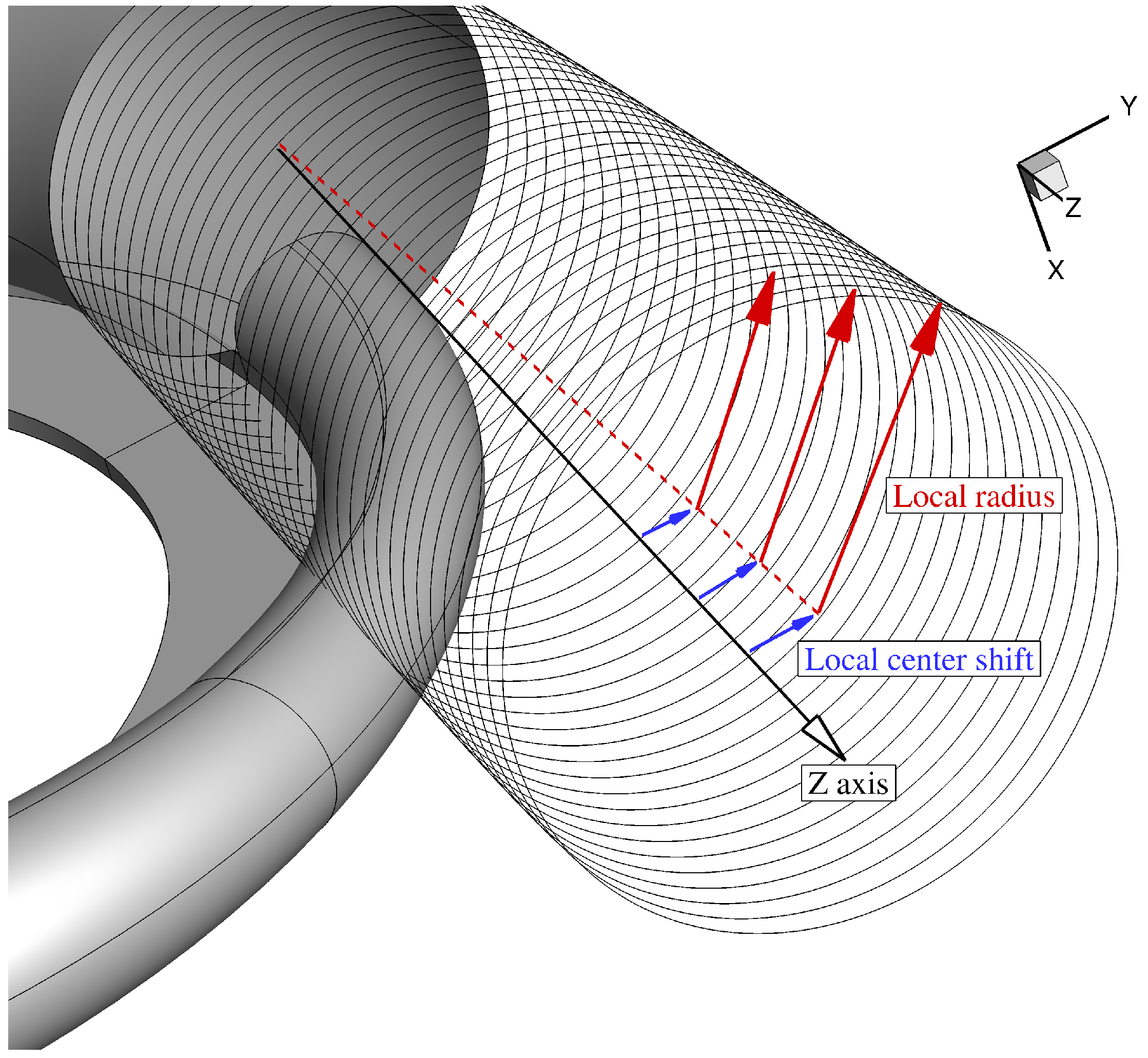
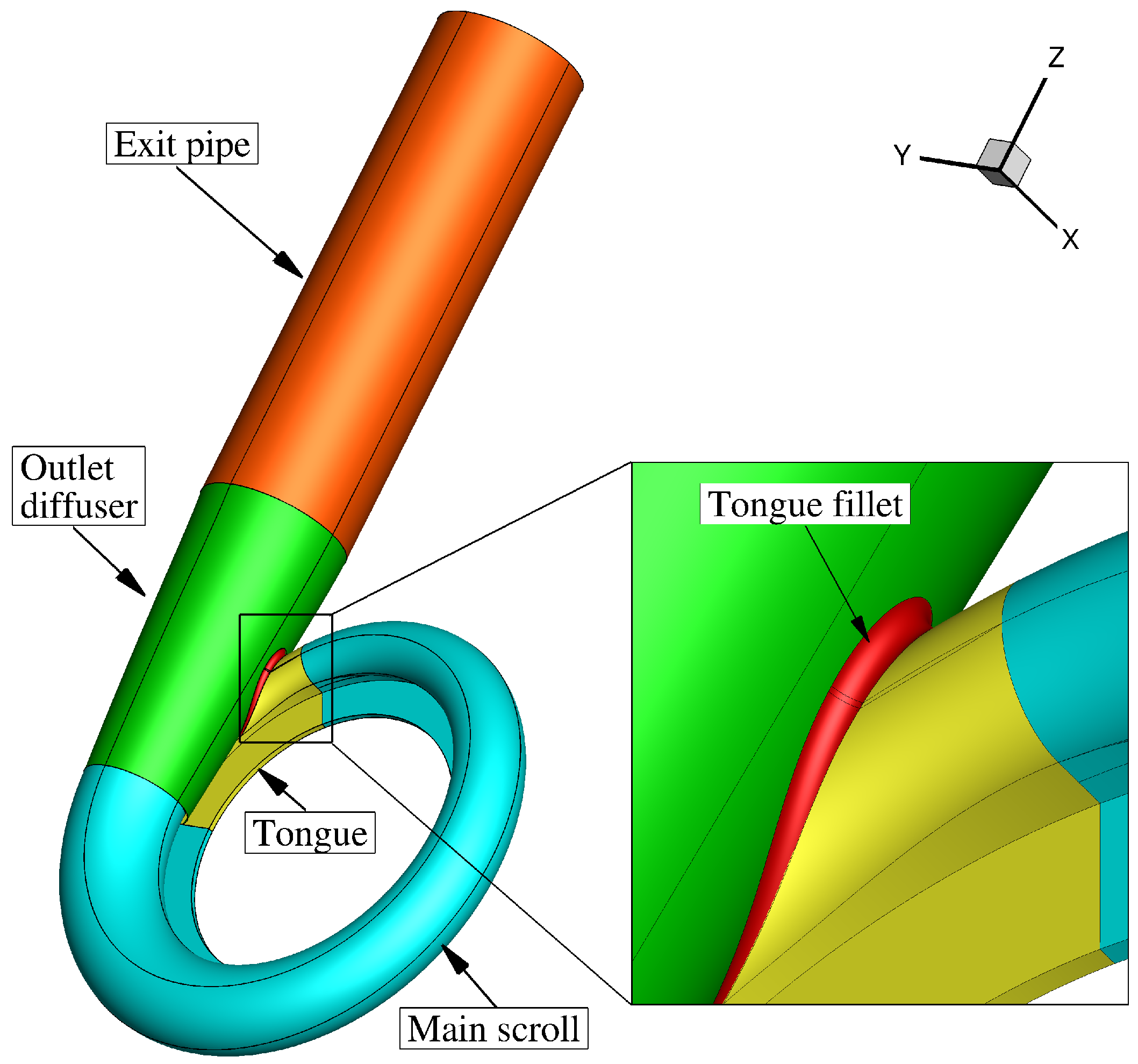
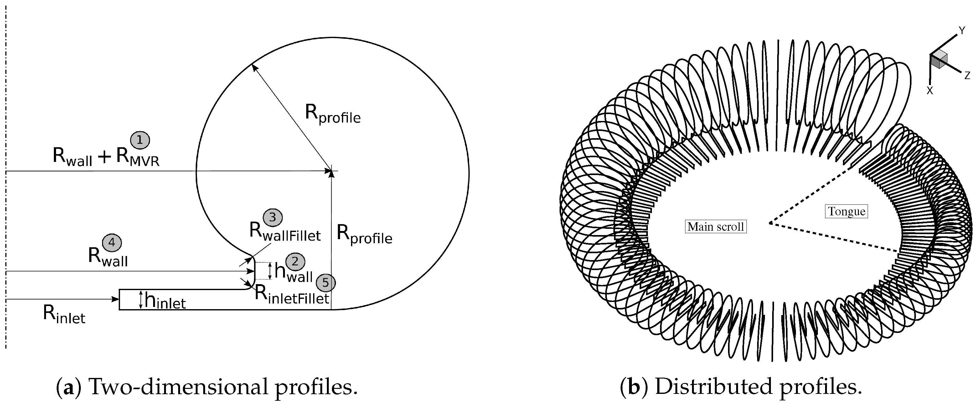
2.1. Geometry Definition
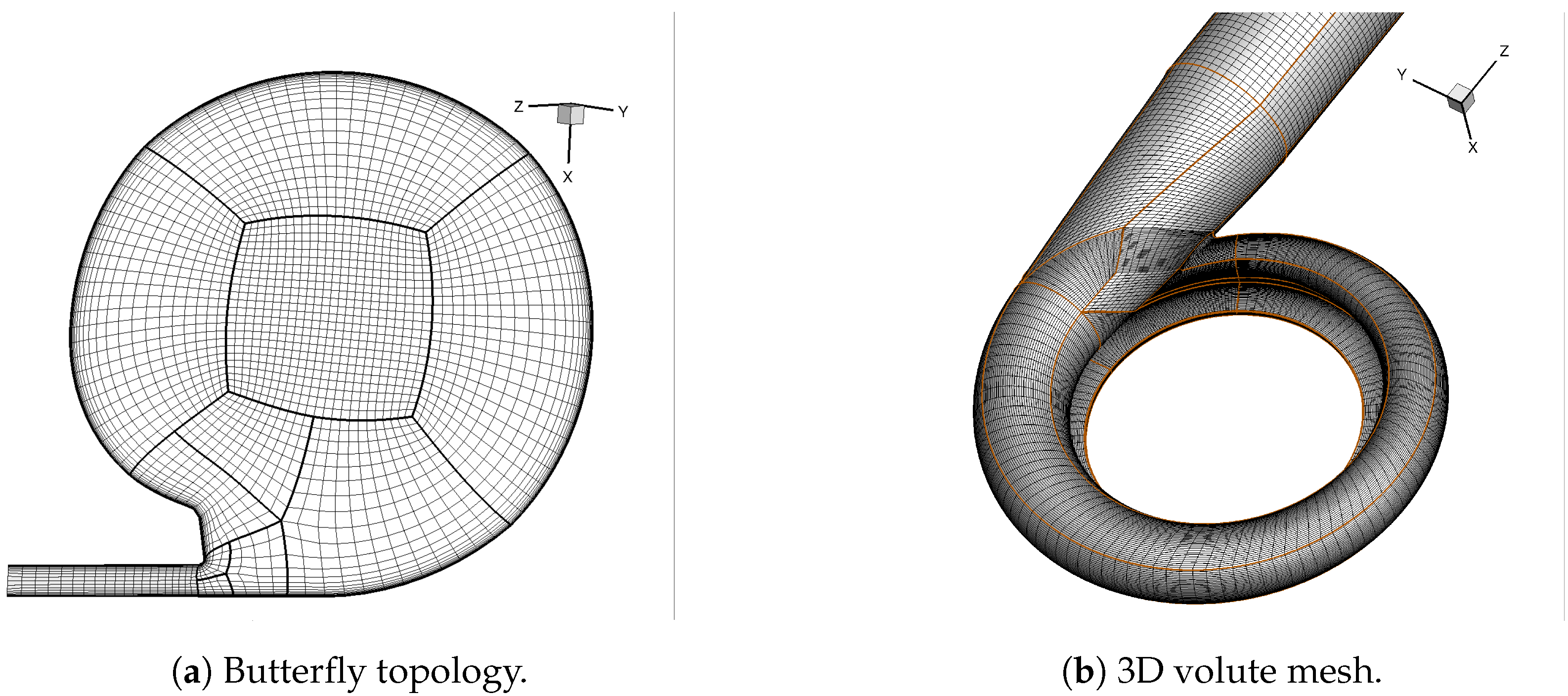
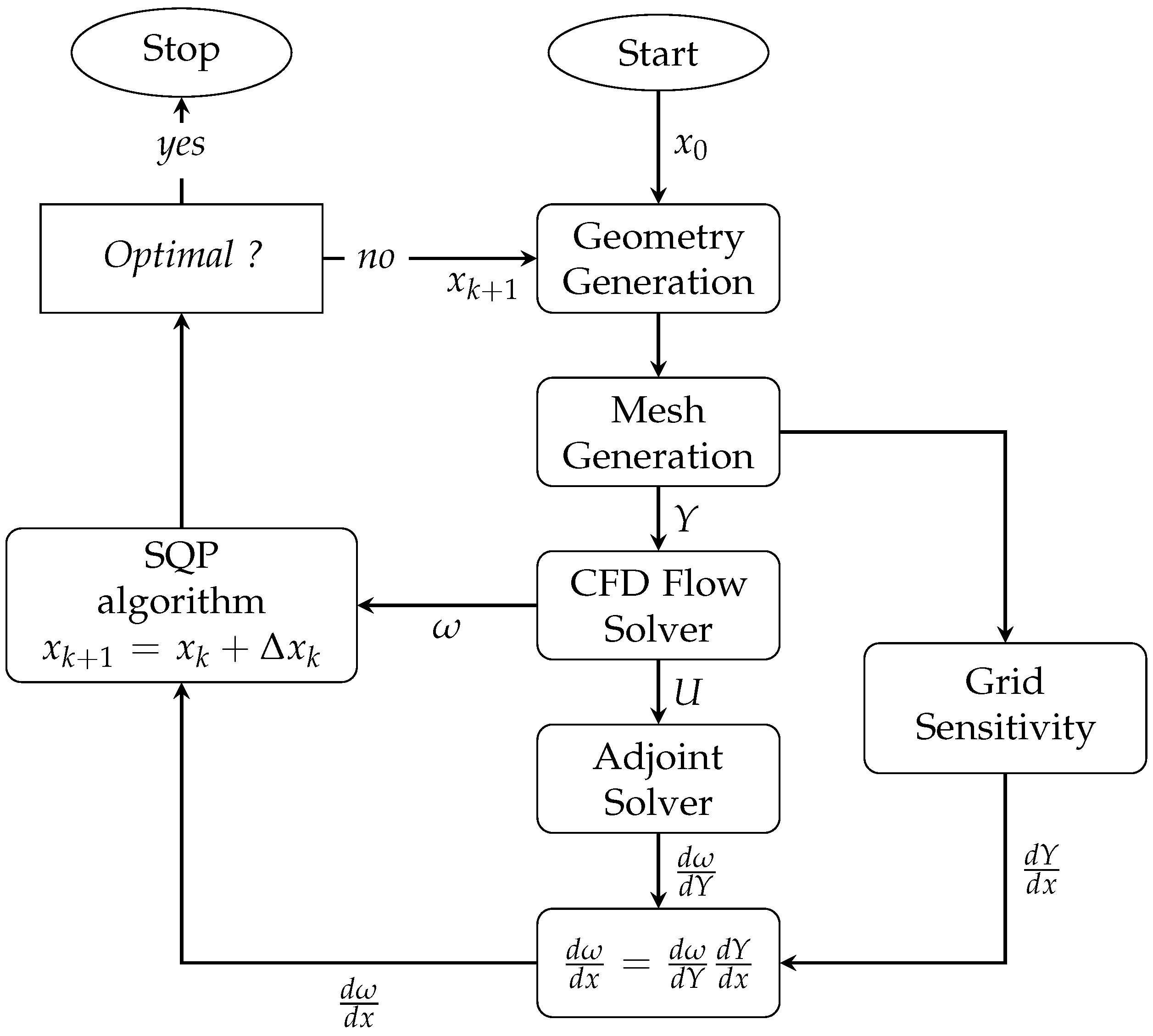
2.2. Numerical Framework
2.3. Preliminary Setup for Optimization
3. Volute Optimization
3.1. Objective Definition
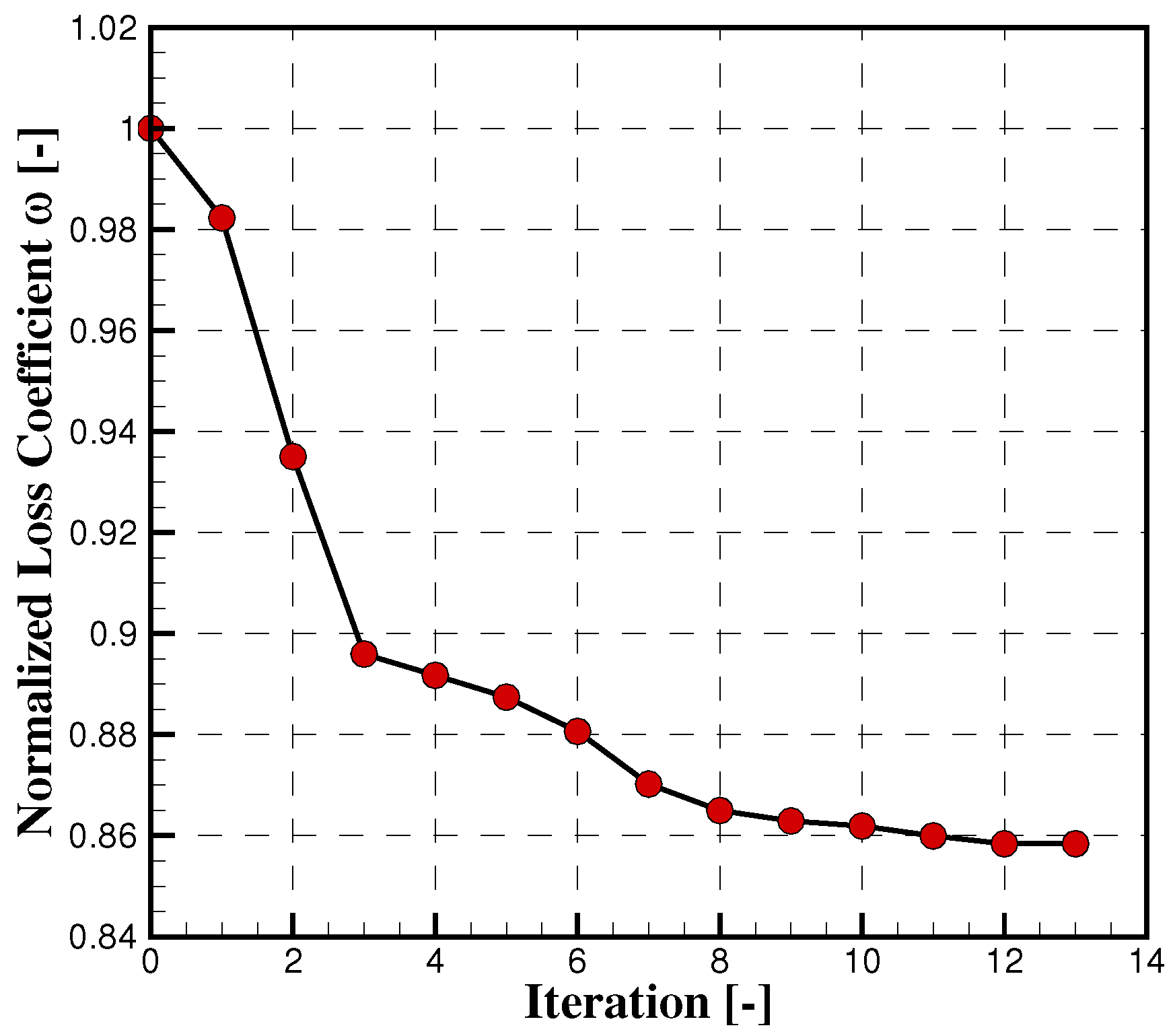
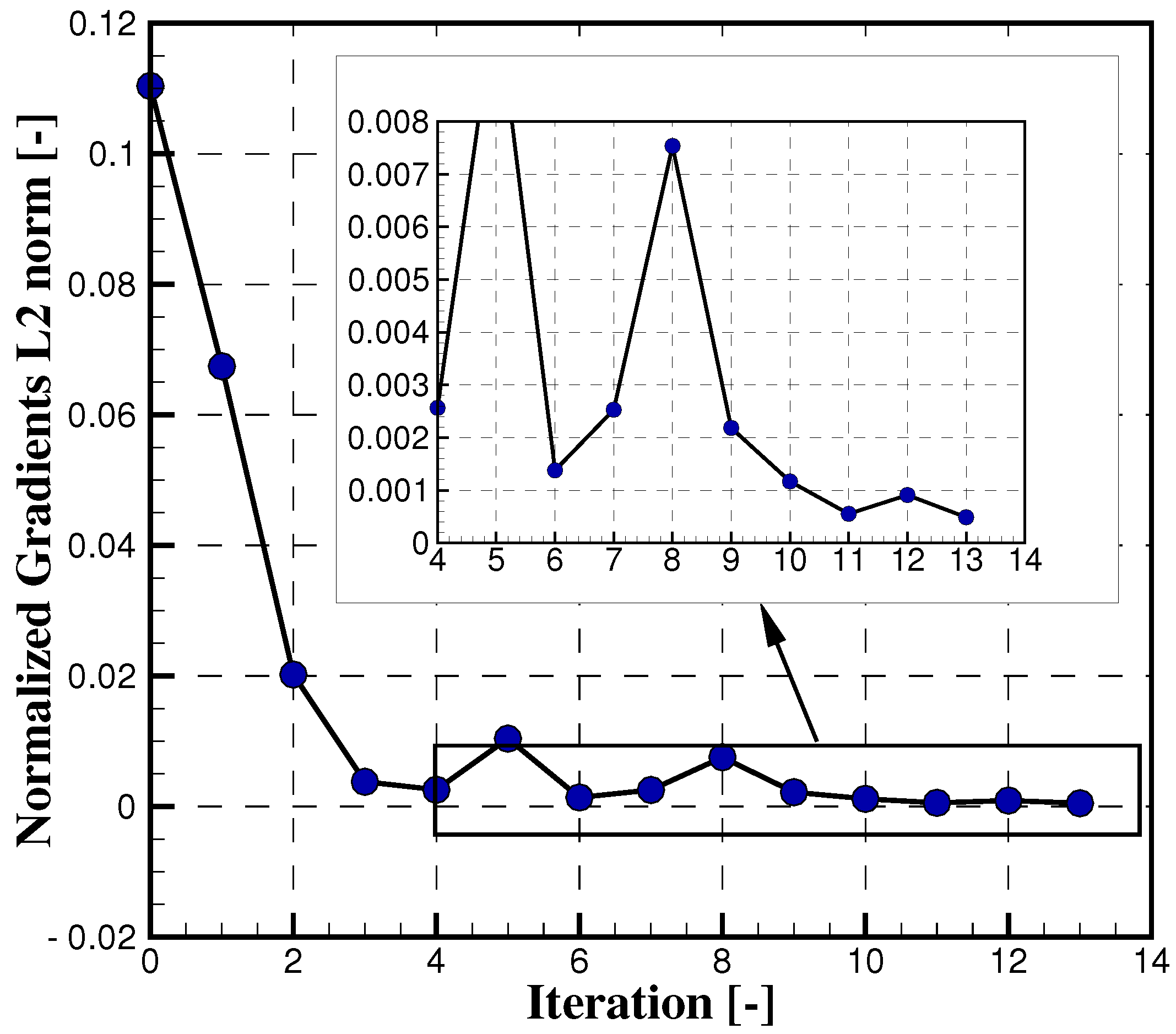
3.2. Optimization Results
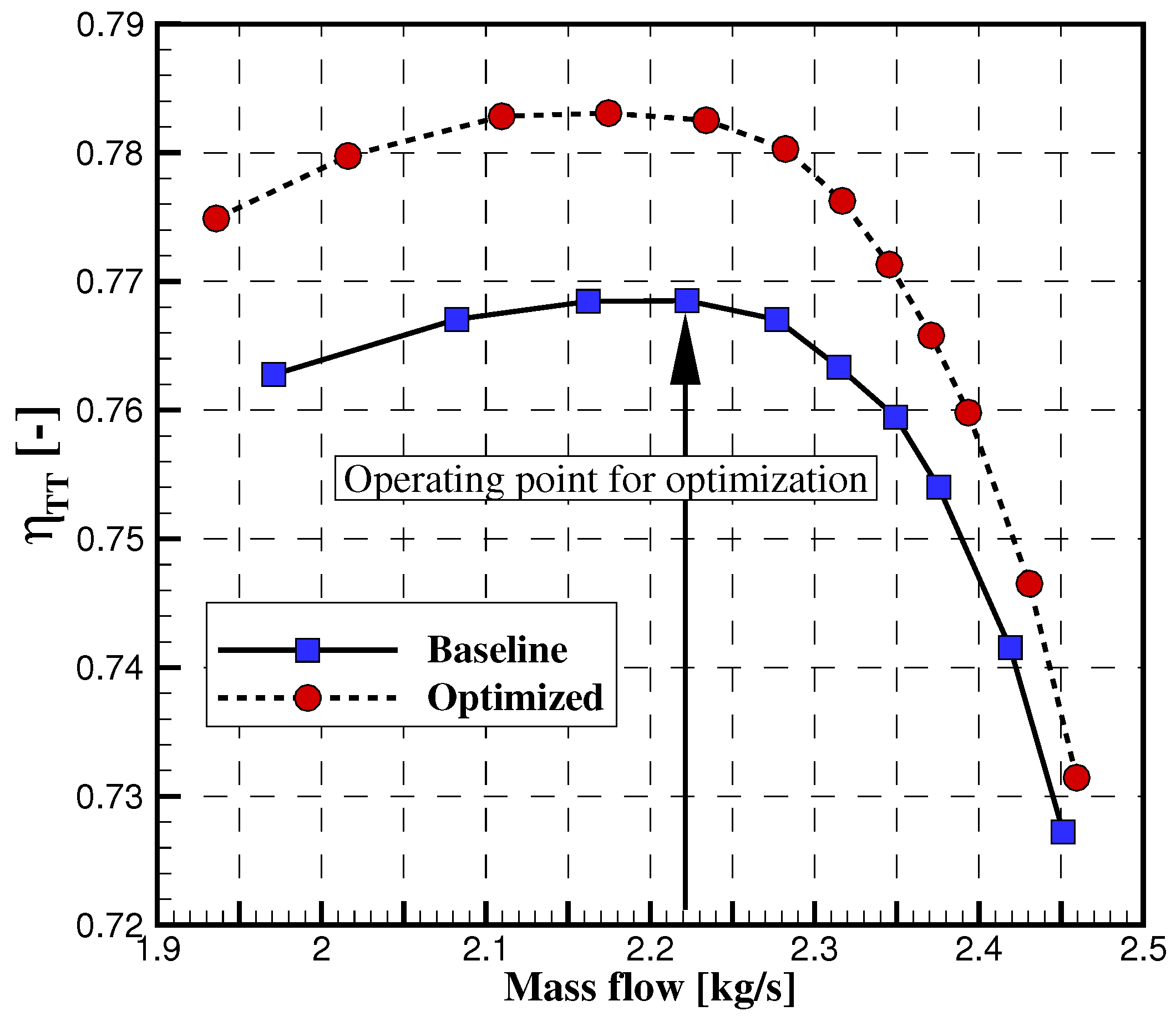
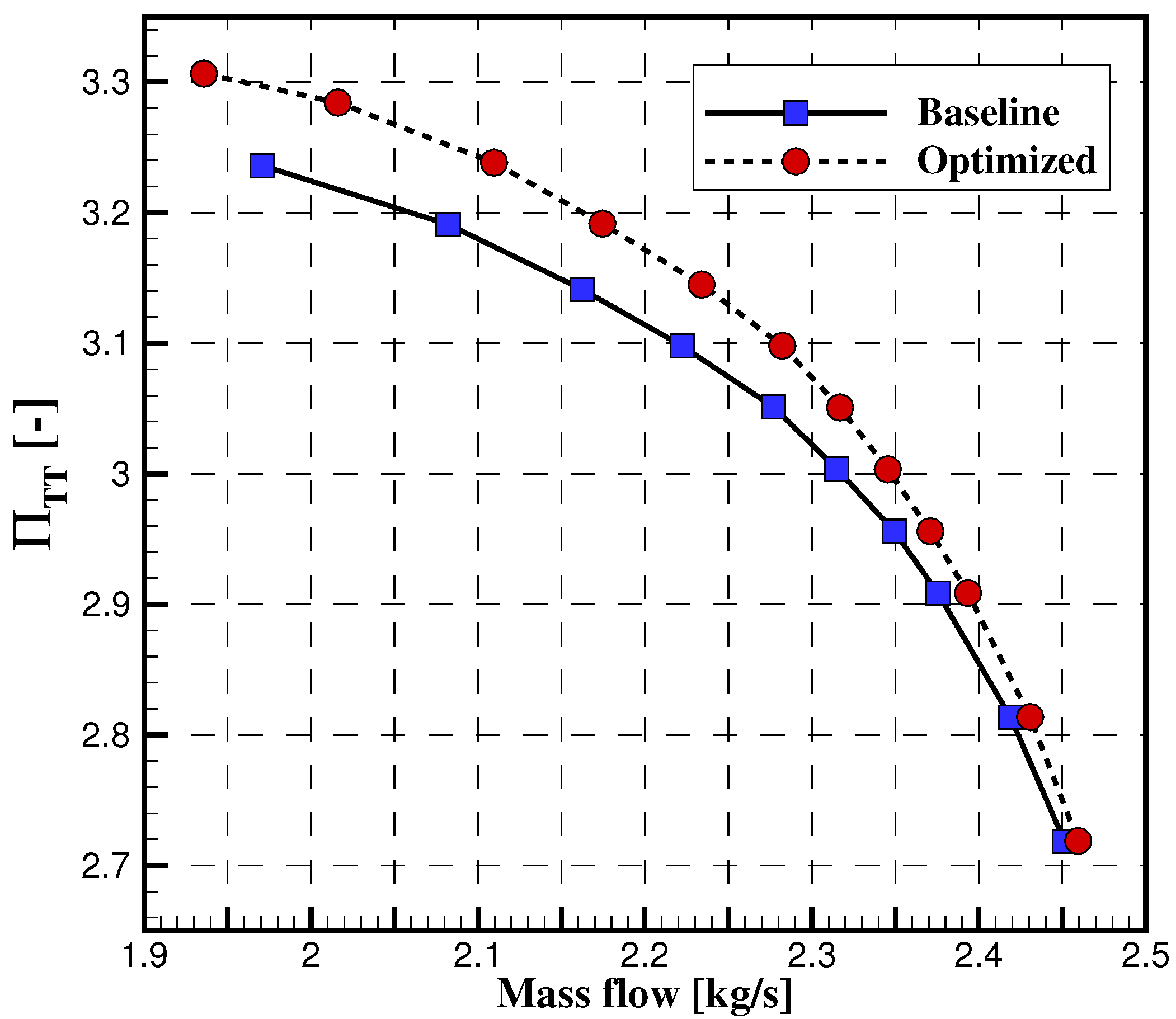
3.3. Updated Compressor Map
4. Conclusions
Author Contributions
Funding
Institutional Review Board Statement
Informed Consent Statement
Data Availability Statement
Acknowledgments
Conflicts of Interest
Abbreviations
| R | Radius |
| h | Height |
| x | Design variable |
| Y | Grid co-ordinates |
| U | Flow solution |
| Inlet flow angle | |
| p | Static pressure |
| T | Static temperature |
| Efficiency | |
| Pressure loss coefficient | |
| Static pressure recovery coefficient | |
| V | Absolute flow velocity |
| Pressure ratio | |
| Adjoint variables | |
| Flow residuals | |
| Adjoint residuals | |
| CFDs | Computational fluid dynamics |
| RANS | Reynolds averaged Navier-Stokes |
| SQP | Sequential quadratic programming |
| lb | Lower bound |
| ub | Upper bound |
| tot | Total |
| in | Inlet |
| out | Outlet |
| TT | Total-to-total |
| t | Tangential |
| r | Radial |
References
- Kim, J.H.; Oh, K.T.; Pyun, K.B.; Kim, C.K.; Choi, Y.S.; Yoon, J.Y. Design optimization of a centrifugal pump impeller and volute using computational fluid dynamics. IOP Conf. Ser. Earth Environ. Sci. 2012, 15, 032025. [Google Scholar] [CrossRef]
- Stepanoff, A.J. Centrifugal and Axial Flow Pumps: Theory, Design, and Application; Krieger Publishing Company: Malabar, NJ, USA, 1993. [Google Scholar]
- Han, X.; Kang, Y.; Sheng, J.; Hu, Y.; Zhao, W. Centrifugal pump impeller and volute shape optimization via combined NUMECA, genetic algorithm, and back propagation neural network. Struct. Multidiscip. Optim. 2020, 61, 381–409. [Google Scholar] [CrossRef]
- Ji, C.; Wang, Y.; Yao, L. Numerical Analysis and Optimization of the Volute in a Centrifugal Compressor. In Challenges of Power Engineering and Environment; Cen, K., Chi, Y., Wang, F., Eds.; Springer: Berlin/Heidelberg, Germany, 2007; pp. 1352–1356. [Google Scholar]
- Huang, J.; Xu, S.; Liu, H.; Wang, X. Robust performance optimization of centrifugal compressor volute with a rectangular cross-section. In Proceedings of the ASME Turbo Expo 2015: Turbine Technical Conference and Exposition, Montréal, QC, Canada, 15–19 June 2015. No. GT2015-42979. [Google Scholar]
- Heinrich, M.; Schwarze, R. Genetic Algorithm Optimization of the Volute Shape of a Centrifugal Compressor. Int. J. Rotating Mach. 2016, 13, 4849025. [Google Scholar] [CrossRef]
- Hottois, R.; Chatel, A.; Verstraete, T. Adjoint-based design optimization of a volute for radial compressor. In Proceedings of the 15th European Turbomachinery Conference, Budapest, Hungary, 24–28 April 2023; paper n. ETC2023-173. Available online: https://www.euroturbo.eu/publications/conference-proceedings-repository/ (accessed on 16 July 2023).
- Eisenlohr, G.; Krain, H. Investigation of the flow through a high pressure ratio centrifugal impeller. In Proceedings of the ASMETurbo Expo 2002: Power for Land, Sea, and Air, Amsterdam, The Netherlands, 3–6 June 2002. No. GT2002-30394. [Google Scholar]
- Chatel, A.; Verstraete, T. Aerodynamic optimization of the SRV2 radial compressor using an adjoint-based optimization method. In Proceedings of the ASME Turbo Expo 2022, Rotterdam, The Netherlands, 13–17 June 2022. [Google Scholar]
- Liseikin, V.D. Grid Generation Methods, 3rd ed.; Springer: New York, NY, USA, 2017. [Google Scholar]
- Thompson, J.F.; Warsi, Z.U.A.; Mastin, C.W. Numerical Grid Generation: Foundations and Applications; North-Holland: Amsterdam, The Netherlands, 1985. [Google Scholar]
- Muller, L. Adjoint-Based Optimization of Turbomachinery with Applications to Axial and Radial Turbines. Ph.D. Thesis, Universite Libre de Bruxelles, Ecole Polytechnique de Bruxelles, Bruxelles, Belgium, 2019. [Google Scholar]
- Wang, D. An Improved Mixing-Plane Method for Analyzing Steady Flow through Multiple-Blade-Row Turbomachine. J. Turbomach. 2014, 136, 081003. [Google Scholar] [CrossRef]
- Giles, M. Non-Reflecting Boundary Conditions for the Euler Equations. AIAA J. 1990, 28, 2050–2058. [Google Scholar] [CrossRef]
- Xu, S.; Radford, D.; Meyer, M.; Müller, J.-D. Stabilisation of Discrete Steady Adjoint Solvers. J. Comput. Phys. 2015, 299, 175–196. [Google Scholar] [CrossRef]
- Martins, J.R.R.A.; Sturdza, P.; Alonso, J.J. The Complex-Step Derivative Approximation. ACM Trans. Math. Softw. 2003, 29, 245–262. [Google Scholar] [CrossRef]
- Hottois, R.; Chatel, A.; Coussement, G.; Debruyn, T.; Verstraete, T. Comparing gradient-free and gradient-based multi-objective optimization methodologies on the VKI-LS89 turbine vane test case. J. Turbomach. 2022, 145, 031001. [Google Scholar] [CrossRef]
- Rosemeier, J. Numerical Analysis of a Centrifugal Compressor Including a Vaneless Diffuser and a Volute. 2017. Available online: https://api.semanticscholar.org/CorpusID:54817508 (accessed on 16 July 2023).
- Van den Braembussche, R. Design and Analysis of Centrifugal Compressors; ASME Press, Wiley: New York, NY, USA, 2019. [Google Scholar]
- Sun, Z.; Zheng, X.; Linghu, Z.; Kawakubo, T.; Tamaki, H.; Wang, B. Influence of volute design on flow field distortion and flow stability of turbocharger centrifugal compressors. Proc. Inst. Mech. Eng. Part J. Automob. Eng. 2019, 233, 484–494. [Google Scholar] [CrossRef]
- Japikse, D. Advanced diffusion levels in turbocharger compressors and component matching. In Proceedings of the First International Conference on Turbocharging and Turbochargers, London, UK, 16–17 May 1982; pp. 143–155. [Google Scholar]
- Alemi, H.; Nourbakhsh, S.A.; Raisee, M.; Najafi, A.F. Effect of the volute tongue profile on the performance of a low specific speed centrifugal pump. Proc. Inst. Mech. Eng. Part A J. Power Energy 2014, 229, 210–220. [Google Scholar] [CrossRef]


| Radial inflow component | [-] | 0.6428 | |
| Axial inflow component | [-] | 0 | |
| Inlet total pressure | [Pa] | 343,000 | |
| Inlet total temperature | [K] | 453 | |
| Outlet static pressure | [Pa] | 310,000 |
| Index | Parameter Name | Baseline | Optimized | Units |
|---|---|---|---|---|
| 1 | Minimum volute radius | 0.023 | 0.017 | [m] |
| 2 | Wall height | 0.008 | 0.0074 | [m] |
| 3 | Wall fillet radius | 0.0025 | 0.001 | [m] |
| 4 | Wall radius | 0.195 | 0.195 | [m] |
| 5 | Inlet fillet radius | 0.001 | 0.0012 | [m] |
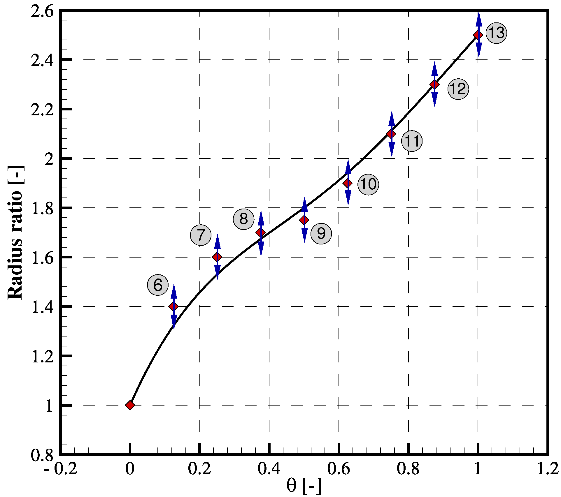
| 6 | Radius ratio point 2 | 1.4 | 1.22844 | [-] |
| 7 | Radius ratio point 3 | 1.6 | 1.45406 | [-] |
| 8 | Radius ratio point 4 | 1.7 | 1.72688 | [-] |
| 9 | Radius ratio point 5 | 1.75 | 2.06383 | [-] |
| 10 | Radius ratio point 6 | 1.9 | 2.22392 | [-] |
| 11 | Radius ratio point 7 | 2.1 | 2.26456 | [-] |
| 12 | Radius ratio point 8 | 2.3 | 2.35792 | [-] |
| 13 | Radius ratio point 9 | 2.5 | 3.08543 | [-] |
| 14 | Tongue radius | 0.005 | 0.0058 | [m] |
Disclaimer/Publisher’s Note: The statements, opinions and data contained in all publications are solely those of the individual author(s) and contributor(s) and not of MDPI and/or the editor(s). MDPI and/or the editor(s) disclaim responsibility for any injury to people or property resulting from any ideas, methods, instructions or products referred to in the content. |
© 2023 by the authors. Licensee MDPI, Basel, Switzerland. This article is an open access article distributed under the terms and conditions of the Creative Commons Attribution (CC BY-NC-ND) license (https://creativecommons.org/licenses/by-nc-nd/4.0/).
Share and Cite
Hottois, R.; Châtel, A.; Verstraete, T. Adjoint-Based Design Optimization of a Volute for a Radial Compressor. Int. J. Turbomach. Propuls. Power 2023, 8, 41. https://doi.org/10.3390/ijtpp8040041
Hottois R, Châtel A, Verstraete T. Adjoint-Based Design Optimization of a Volute for a Radial Compressor. International Journal of Turbomachinery, Propulsion and Power. 2023; 8(4):41. https://doi.org/10.3390/ijtpp8040041
Chicago/Turabian StyleHottois, Romain, Arnaud Châtel, and Tom Verstraete. 2023. "Adjoint-Based Design Optimization of a Volute for a Radial Compressor" International Journal of Turbomachinery, Propulsion and Power 8, no. 4: 41. https://doi.org/10.3390/ijtpp8040041
APA StyleHottois, R., Châtel, A., & Verstraete, T. (2023). Adjoint-Based Design Optimization of a Volute for a Radial Compressor. International Journal of Turbomachinery, Propulsion and Power, 8(4), 41. https://doi.org/10.3390/ijtpp8040041