Article

Simulation of Indexing and Clocking with a New Multidimensional Time Harmonic Balance Approach †

Institute of Propulsion Technology, German Aerospace Center (DLR), Linder Höhe, 51147 Cologne, Germany
*
Author to whom correspondence should be addressed.
This paper is an extended version of our paper published in the Proceedings of the 16th International Symposium on Unsteady Aerodynamics, Aeroacoustics and Aeroelasticity of Turbomachines, Toledo, Spain, 19–23 September 2022; paper No. 004.
Current address: Leybold GmbH (Part of the Atlas Copco Group), Germany.
Int. J. Turbomach. Propuls. Power 2024, 9(2), 17; https://doi.org/10.3390/ijtpp9020017
Submission received: 17 October 2023 / Revised: 28 March 2024 / Accepted: 2 April 2024 / Published: 8 May 2024

Abstract

:
Alongside the capability to simulate rotor–stator interactions, a central aspect within the development of frequency-domain methods for turbomachinery flows is the ability of the method to accurately predict rotor–rotor and stator–stator interactions on a single-passage domain. To simulate such interactions, state-of-the-art frequency-domain approaches require one fundamental interblade phase angle, and therefore it can be necessary to resort to multi-passage configurations. Other approaches neglect the cross-coupling of different harmonics. As a consequence, the influence of indexing on the propagation of the unsteady disturbances is not captured. To overcome these issues, the harmonic balance approach based on multidimensional Fourier transforms in time, recently introduced by the authors, is extended in this work to account for arbitrary interblade phase angle ratios on a single-passage domain. To assess the ability of the approach to simulate the influence of indexing on the steady, as well as on the unsteady, part of the flow, the proposed extension is applied to a modern low-pressure fan stage of a civil aero engine under the influence of an inhomogeneous inflow condition. The results are compared to unsteady simulations in the time-domain and to state-of-the-art frequency-domain methods based on one-dimensional discrete Fourier transforms.

1. Introduction

Over the past decades, computational fluid dynamics has developed a significant impact on the multidisciplinary design of modern turbomachines. In nearly all design phases, numerical simulations with different fidelity are performed and experimental validation of engines on test rigs has been reduced to a minimum. In terms of high-fidelity methods, frequency-domain approaches have become a state-of-the-art technique for the simulation of unsteady periodic flows within multistage turbomachinery. Over the past decades, significant contributions to its further development have been made in research and industry [1,2,3,4,5,6,7]. However, it still remains a significant challenge to capture nonlinear interaction effects within the context of configurations with multiple fundamental frequencies. To overcome this issue, a new harmonic balance approach based on multidimensional discrete Fourier transforms (MDFTs) in time has recently been introduced by the authors [8]. The crucial idea of the multidimensional Fourier approach is to extend the one-dimensional time to multiple time dimensions so that each periodic flow phenomenon is described by a combination of sampling points in the multidimensional time. In this way, the intricate issue of defining common sampling points for incommensurable frequencies is avoided. In a similar fashion, the frequency domain is extended to a multidimensional frequency domain, so that every frequency is an integer linear combination of the involved fundamental frequencies. In this way, the proposed method is capable of fully integrating the nonlinear coupling effects between higher harmonics of different fundamental frequencies by using multidimensional discrete Fourier transforms within the harmonic balance solution procedure.
Alongside the capability to simulate rotor–stator interactions, a central aspect within the development of frequency-domain methods for turbomachinery flows is the capability of the method to accurately predict rotor–rotor and stator–stator interactions, preferably on a single-passage domain. In turbomachinery, these effects mostly occur in the form of clocking and indexing. The term clocking refers to the dependency of the machine’s performance on the relative circumferential positioning of the rotors or stators. The more general term indexing describes the underlying effect that different blade or vane counts lead to a circumferentially asymmetric flow.
In the terminology of frequency-domain methods, the rotor–rotor and stator–stator interactions can be viewed as additional harmonics with zero frequency and non-zero interblade phase angle. The interacting rotors or stators, respectively, are in most cases positioned on the same shaft with the same rotational speed and therefore the disturbances generated by the upstream blade row are seen by the downstream non-adjacent blade row with zero frequency. To avoid resonance effects, the blade counts of the interacting blade rows are typically chosen to be different. As a consequence, the zero-frequency disturbances induce a circumferential asymmetry on the time-averaged flow, or in other words a non-zero interblade phase angle.
A central drawback of approaches based on a standard one-dimensional discrete Fourier transform (DFT) is that if no fundamental interblade phase angle exists, the method is not capable of simulating harmonics that only differ in their interblade phase angle on a single passage domain and it can be necessary to resort to multi-passage configurations. The indexing extension of the harmonic set approach [9] resolves this drawback by defining a zero-frequency harmonic set with a non-zero interblade phase angle and approximates the ( 0 , σ ) -harmonic of the residual by a weighted sum. This approach is closely related to the approach by [10], who generalised the Nonlinear Harmonic (NLH) method to zero-frequency perturbations. In this way, the rotational asymmetries in the mean flow can be captured on a single-passage domain. However, both approaches neglect the interaction between the higher harmonics of the zero-frequency disturbance with higher harmonics of other non-zero frequency disturbances. More precisely, each non-zero frequency disturbance experiences the same mean flow in every blade passage, since the interactions between the perturbations only occur through the zeroth harmonic. As a consequence, the influence of indexing or clocking on the propagation of unsteady disturbances is not captured. Another approach is to introduce a small, fictitious shift of the rotation speed, even for stators, to obtain a configuration with multiple base frequencies [7]. However, this can result in a large number of frequencies and sampling points in every blade row and may diminish the computational advantage of the harmonic balance method.
To overcome these issues described above, the multidimensional harmonic balance approach is extended in this work to account for the impact of indexing on the steady, as well as on the unsteady, part of the flow using only a single-passage domain per blade row. To demonstrate the capability of this extension to capture rotationally asymmetric flow on a single-passage domain, a modern low-pressure fan stage of a civil aero engine under the influence of an inhomogeneous inflow condition is investigated. Whilst the rotor is subject to the imposed periodic variation in the inflow condition, the stator has a fixed relative position with respect to the inflow distortion and therefore exhibits indexing. The results of the multidimensional harmonic balance approach are compared to unsteady simulations in the time domain and to state-of-the-art frequency-domain methods based on one-dimensional discrete Fourier transforms.

2. Numerical Method

2.1. Harmonic Balance Technique

The basic idea of frequency-domain techniques is to obtain approximate solutions of the unsteady Favre-and-Reynolds-averaged Navier Stokes (URANS) equations
q ( t ) t + R q ( t ) = 0 .
If the spectrum of the unsteady flow field consists of arbitrary integer combinations of a finite number of fundamental modes, then the base frequency vector is denoted by
ω b = ω b 0 , , ω b M 1 R M
and the base interblade phase angle vector by
σ b = σ b 0 , , σ b M 1 R M .
With the variables of the counterpart system denoted as a primed variable, the interblade phase angle is defined by
σ b = 2 π B sgn Ω Ω B = 2 π m B = m Δ ϑ .
Assuming that the spectrum consists only of integer combinations of a finite number of fundamental frequencies in ω b , then each unique frequency can be represented by the scalar product
k , ω b = m = 0 M 1 k m ω m = k 0 ω b 0 + + k M 1 ω b M 1 ,
where k m is any value k K m and the m-th set of harmonic indices is then given by
K m = k Z | K m k K m
bounded by some upper and lower sidebands K m and K m . Likewise, the corresponding integer combinations of a finite number of interblade phase angles in σ b are represented by the scalar product
k , σ b = m = 0 M 1 k m σ m = k 0 σ b 0 + + k M 1 σ b M 1 .
Since each harmonic is defined by its frequency and interblade phase angle, the set of all harmonics is given by
S = k , ω b , k , σ b | k m K m .
If the whole unsteady flow field is quasi-periodic with frequencies in the finite set S , then the vector of conservative variables q ( t ) can be represented as a Fourier series of the form
q x , r , ϑ , t = Re ω , σ S q ^ ω , σ x , r , ϑ e i ω t
where q ^ ω , σ denotes the Fourier coefficient associated with the frequency ω and the interblade phase angle σ . Based on this, the unsteady Equation (1) is reformulated in the frequency domain
i ω q ^ ( ω , σ ) + R q ^ ( ω , σ ) = 0 .
The harmonic balance method in this work is an alternating frequency–time-domain approach using the discrete Fourier transform F and its inverse F 1 to incorporate the nonlinearities implicitly
i ω q ^ ( ω , σ ) + F ( R ( F 1 q ^ ) ) ( ω , σ ) = 0 .

2.2. Extension to Rotationally Asymmetric Flow
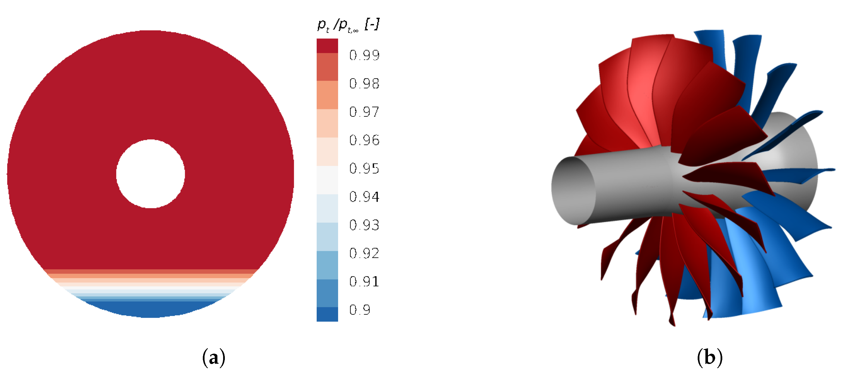
In the terminology of frequency-domain methods, the rotational asymmetry in the mean flow can be described by harmonics with zero frequency and a non-zero interblade phase angle. Moreover, in case of zero-frequency disturbances, the notion of a sampling point t i is replaced with the respective sampling phase φ l corresponding to circumferential positions rather than time instants [11]. Each sampling point corresponds to a specific passage index l. If one considers a configuration consisting of a stator, a rotor and a second stator with blade counts B S 1 , B R and B S 2 , then instead of φ i = ω t i for disturbances with frequency ω > 0 , the zero-frequency case is given by
λ l = 2 π k S 1 B S 1 B S 2 l = σ l .
The crucial idea of applying the multidimensional harmonic balance approach to circumferentially varying flow, is to represent this variation in a multidimensional phase domain. More precisely, each interblade phase angle k , σ b is identified with a multidimensional interblade phase angle
k σ b = k 0 σ b 0 , , k M 1 σ b M 1
and the reconstruction of the flow field with respect to the multidimensional passage indices is then given by
q ˜ x , r , ϑ , l 0 , l 1 , = Re k 0 K 0 k M 1 K M 1 q ^ k 0 , , k M 1 x , r , ϑ e i k 0 σ b 0 l 0 + + k M 1 σ b M 1 l M 1 k 0 K 0 .
In the case of M fundamental interblade phase angles, then for every base interblade phase angle σ b m a separate phase dimension is introduced. Each harmonic of the interblade phase angle is then defined by an M-dimensional integer vector k in the M-ary Cartesian product over M sets according to
K = K 0 × × K M 1 = k 0 , , k M 1 | k m K m .
For every base interblade phase angle in the interblade phase angle basis vector Equation (3), a separate passage index axis l m in a multidimensional passage domain l is spanned. The M-dimensional passage domain is represented by a hyperphase vector λ of length M
λ = λ 0 , , λ M 1 = σ b l = σ b 0 l 0 , , σ b M 1 l M 1 R M
by introducing auxiliary 2 π -periodic phase variables λ i , one for each base interblade phase angle σ b m . With the definition of appropriate sampling phases λ l that correspond to a circumferentially equidistant distribution of Δ l sampling phases in the interval [ 0 , 2 π ) according to
λ l = 2 π l Δ l = 2 π l gcd ( B S 1 , B S 2 ) B S 2 l = 0 , , Δ l 1 ,
every passage dimension has a set of L m passage indices
L m = l i Z | 0 i L m 1
and the complete set of indices covering the M-dimensional passage domain is given by the M-ary Cartesian product of the indices for each passage axis
L = L 0 × × L M 1 = l 0 , , l M 1 | l m L m .
In this way, the MDFT approach is able to incorporate the influence of indexing on the steady part of the flow. To furthermore consider the influence of indexing on the unsteady part of the flow, the cross-coupling of the non-zero and zero-frequency disturbances is computed as the Cartesian product
L × T = L 0 × × L M 1 × T 0 × × T M 1 = l 0 , , l M 1 , t 0 , , t M 1 | l m L m , t m T m ,
where every frequency dimension has a set of N m sampling points
T m = t i R | 0 i N m 1
in the interval
0 t i < 2 π ω b m .
The forward and backward discrete multidimensional Fourier transforms extended by the cross-coupling between non-zero and zero frequencies are then given by
q x , r , ϑ , t , l = Re k K q ^ k x , r , ϑ e i k , τ + k , λ R ^ ( k , ω b ) , ( k , σ b ) x , r , ϑ = ψ ω 1 N L t T l L R q x , r , ϑ , t , l e i k , τ + k , λ
with the prefactor of the Fourier transform
ψ ω = 1 , if ω = 0 2 , if ω > 0 ,
the phase vectors
τ = ω b t , λ = σ b l ,
and N = m = 0 M 1 N m and L = m = 0 M 1 L m .
To explain this in more detail, a configuration consisting of a stator, a rotor and a second stator with stator blade count ratio B S 1 / B S 2 = 2 / 5 is considered. The first stator generates disturbances that are captured in the downstream-positioned second stator as zero-frequency harmonics with an interblade phase angle unequal to zero. Furthermore, the rotor generates non-zero frequency disturbances that interact with the disturbances generated by the first stator. For simplicity, in the following only the first harmonic K = 1 of each disturbance is considered.
Figure 1a shows an unfolded view of this interaction in a bi-dimensional time–passage–index domain. For the non-zero frequency disturbance, originating from the relative rotational motion of the rotor, a continuous time axis t is spanned and the period T of the disturbance is marked on the axis. According to the Nyquist–Shannon sampling theorem [12], three discrete sampling points are positioned equidistantly on the axis within this period. Since for zero-frequency disturbances the notion of a sampling point corresponds to a specific passage index l rather than a time instant, a second axis corresponding to the passages of the second stator with indices l = 0 , , L 1 is spanned. In the following, the case where the passage indices correspond to real integer stator positions is considered. The two stator rows with blade count ratio B S 1 / B S 2 = 2 / 5 have a common periodicity of gcd ( B S 1 , B S 2 ) = 1 ; therefore, according to Equation (17) it suffices to sample the passages with integer passage indices l = 0 , , 4 instead of l = 0 , , B S 2 1 , as indicated by the sampling points on the passage indices axis. In contrast to non-zero frequency harmonics, where the discrete time instants can be positioned arbitrarily along the continuous time axis, the sampling indices for the zero-frequency harmonics can only be distributed at discrete passages indicated by the dashed horizontal lines.
To now incorporate the influence of indexing on the unsteady part of the flow, more precisely the cross-coupling between the zero and non-zero frequency disturbances, the Cartesian product of the time instants on the time axis with the passage indices on the passage axis is computed. Then, for every point of the sampling grid a unique and fixed relation between a discrete time instant in a continuous time and a discrete stator position is defined. Furthermore, the passage indices correspond to discrete phase positions on the circumference, as depicted in Figure 1b. The sampling phases of the zero-frequency disturbance are distributed equidistantly in the interval [ 0 , 2 π ) on the phase axis covering the full annulus domain. Furthermore, the non-zero frequency disturbances are represented in the 2 π -periodic hyperphase domain τ = ω b t ; cf. [8]. By computing the Cartesian product of the time instants with the sampling phases, the domain is extended to a multidimensional 2 π -periodic time–phase domain, indicated by the grey background. In this way, the cross-coupling between the non-zero and zero-frequency disturbance is directly included within the MDFT approach.
The multidimensional harmonic balance approach is implemented in the framework of the CFD code TRACE (Turbomachinery Research Aerodynamic Computational Environment). TRACE is a parallel Navier–Stokes flow solver developed at the Institute of Propulsion Technology of the German Aerospace Center (DLR) to model and investigate complex turbomachinery flows [13]. Details on the implementation and validation of the MDFT approach in TRACE can be found in [8].

3. Application

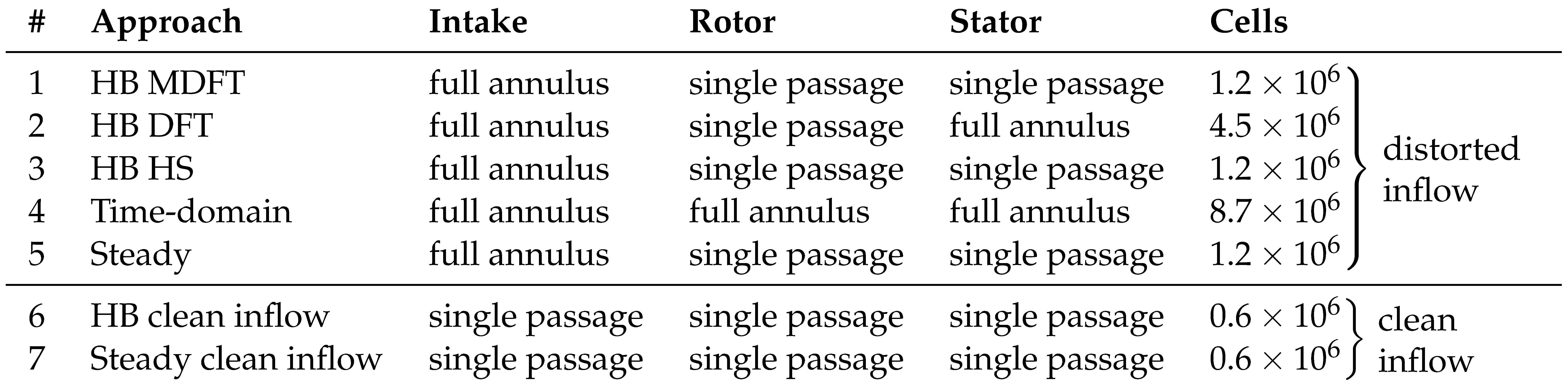
Testcase Description

To validate the indexing extension of the MDFT approach, a modern low-pressure fan stage of a civil aero engine derived from a previous DLR design study [14] under the influence of an inhomogeneous inflow condition is investigated; see Figure 2. The operating point used in the following is the point of maximum efficiency. Here, the fan exhibits a meridional inflow Mach number of 0.65 and a design total pressure ratio of 1.3 . The rotor and stator are composed of 15 blades and 15 vanes, where the rotor is subject to an imposed periodic variation in the inflow condition whilst the stator has a fixed relative position with respect to the inflow distortion and therefore exhibits indexing. The imposed inflow distortion, seen in Figure 2a, models an ingested boundary layer of an airplane fuselage and is similar to the ones presented by [15,16]. The motivation for such boundary layer ingesting systems is that they offer considerable advantages regarding system efficiency and mission fuel burn [17]. The distortion has the form of an ideal turbulent boundary layer that covers 50 % of the inlet duct height in the lower part of the annulus. The highest total pressure distortion in this boundary layer is 12 % relative to the far-field inflow total pressure. Table 1 shows the different simulation approaches and its associated geometry setups. All simulations with distorted inflow use a full annulus inlet duct to prescribe the incoming total pressure distortion as a two-dimensional distribution according to Figure 2a. Downstream, in all frequency-domain simulations a single-rotor passage is employed. In the relative system of the stator, the setups of the frequency-domain approaches with distorted inflow differ. To demonstrate the capability of the multidimensional harmonic balance approach to simulate indexing on a single passage domain, the respective setup, Case 1, includes only one stator passage. In contrast, the approach based on a standard DFT, Case 2, requires a full annulus stator row to capture the circumferential variation of the flow in the second stator without additional adjustments of the approach. However, a factor of ~ 3.75 more mesh cells than the MDFT approach is necessary, which increases the computational costs of the simulation. Case 3 uses a single-passage stator domain in combination with additional zero-frequency harmonic sets as proposed by [9]. By neglecting the influence of indexing or clocking on the propagation of unsteady disturbances, the harmonic set approach allows the reduction in the computational domain to a single-passage stator, leading to the same computational domain as used by the MDFT approach. However, it has to be validated if the approximations made within the harmonic set approach lead to an adequate simulation of the complex interaction mechanisms within this testcase.
To assess the validity and accuracy of the frequency-domain results, all frequency-domain simulations are compared to a full annulus unsteady time-domain simulation with distorted inflow, Case 4, using the BDF2 scheme with 1920 time steps per rotor revolution and 20 subiterations per physical time step. To ensure spatial periodicity in the time-domain simulation, the intake, rotor and stator row have to be duplicated to full annulus domains, which leads to a factor of ~ 7.25 more mesh cells than the MDFT setup. In addition to the unsteady frequency- and time-domain simulations with distorted inflow, Cases 1–4, results obtained with a steady mixing plane approach and distorted inflow are also presented, Case 5. To represent the unsteady design operating conditions of the fan stage, a harmonic balance simulation with clean inflow conditions without inlet distortion, Case 6, has been carried out. Furthermore, a full steady design characteristic with clean inflow, Case 7, at design speed has been computed. Observe, that for the latter two setups with clean inflow conditions, the computational domain of the intake can be reduced to a single passage, whilst the steady simulation with distorted inflow, Case 5, still requires a full annulus intake domain, since the inlet distortion is here also prescribed as a 2D distribution.
In the following, the simulation setup of the indexing extension of the MDFT approach is explained in more detail. For this approach, the computational domain of the stator only consists of a single passage. As a consequence, the inlet distortion, prescribed on a full annulus intake domain, is captured in the relative system of the stator as a zero-frequency disturbance with an interblade angle unequal to zero; cf. Equation (4). Furthermore, the rotor generates non-zero frequency disturbances that are captured in the stator system with the blade passing frequency of the rotor ω R and an interblade phase angle of zero, since the fan stage comprises 15 blades and 15 vanes. Additionally, the interaction of the inlet disturbance with the unsteady flow field of the rotor generates a rotational asymmetry of the unsteady flow field in the stator, which can be expressed by the blade passing frequency of the rotor ω R and an interblade phase angle unequal to zero.
The crucial idea of the indexing extension of the MDFT approach is to represent all of these disturbances in a multidimensional frequency–phase domain; see Figure 3a. Therefore, a dimension for the frequency, as well as a dimension for the circumferential position, denoted as interblade angle, is spanned. The harmonics of the rotor’s blade passing frequency are marked on the frequency axis. Likewise, the inlet distortion as a steady disturbance is marked on the phase axis with zero frequency and an interblade phase angle unequal to zero in the interval [ π , π ) . To now incorporate the influence of indexing on the unsteady part of the flow, i.e., the cross-coupling between the zero and non-zero frequency disturbances, all possible frequency–phase combinations are computed according to k , ω b + k , σ b . Observe that the mode equality ( ω , m ) = ( ω , m ) with the circumferential wavenumber m and the interblade phase angle σ according to Equation (4) is taken into account, so that modes are not included multiple times.
Figure 3b shows an unfolded view of the corresponding time–passage domain. For the non-zero frequency disturbance, originated from the relative rotational motion of the rotor, a continuous time axis t is spanned and the period T of the disturbance is marked on the axis. According to [18], 33 discrete sampling points are positioned equidistantly on the axis within this period. Since for zero-frequency disturbances the notion of a sampling point corresponds to a specific passage index rather than a time instant, a second axis consisting of the stator’s passages with indices l = 0 , , 14 is spanned. The fan intake and the stator with blade count ratio B I n / B S = 1 / 15 have a common periodicity of gcd ( B I n , B S ) = 1 . Therefore, all 15 stator passages, marked by the sampling points on the vertical passage index axis, have to be sampled. To now incorporate the influence of indexing on the unsteady part of the flow, i.e., the cross-coupling between the zero and non-zero frequency disturbances, the Cartesian product of the time instants on the time axis with the passage indices on the passage axis is computed. For every point of the sampling grid, a unique and fixed relation between a discrete time instant in a continuous time and a discrete stator position is defined. From this, it follows that multidimensional forward and backward discrete Fourier transforms according to Equations (23) and (24) can be applied in the harmonic balance solution procedure.
To ensure comparability between all simulation methods, for the interface between the rotor and stator, as well as for the exit plane, 2D nonreflecting boundary conditions formulated in the frequency domain have been used for the harmonic balance simulations [6,19,20] and for the time-domain simulation [21,22]. The inlet distortion is prescribed as a 2D distribution; cf. Figure 2a, with Riemann boundary conditions. To model the effects of turbulence, the k- ω turbulence model [23] is used in a transport equation framework for both the frequency- and time-domain simulations. For the frequency-domain simulations, the transport equations are solved for the zeroth harmonic, as well as for the higher harmonics, to include the effect of unsteadiness in the turbulence model.

4. Results

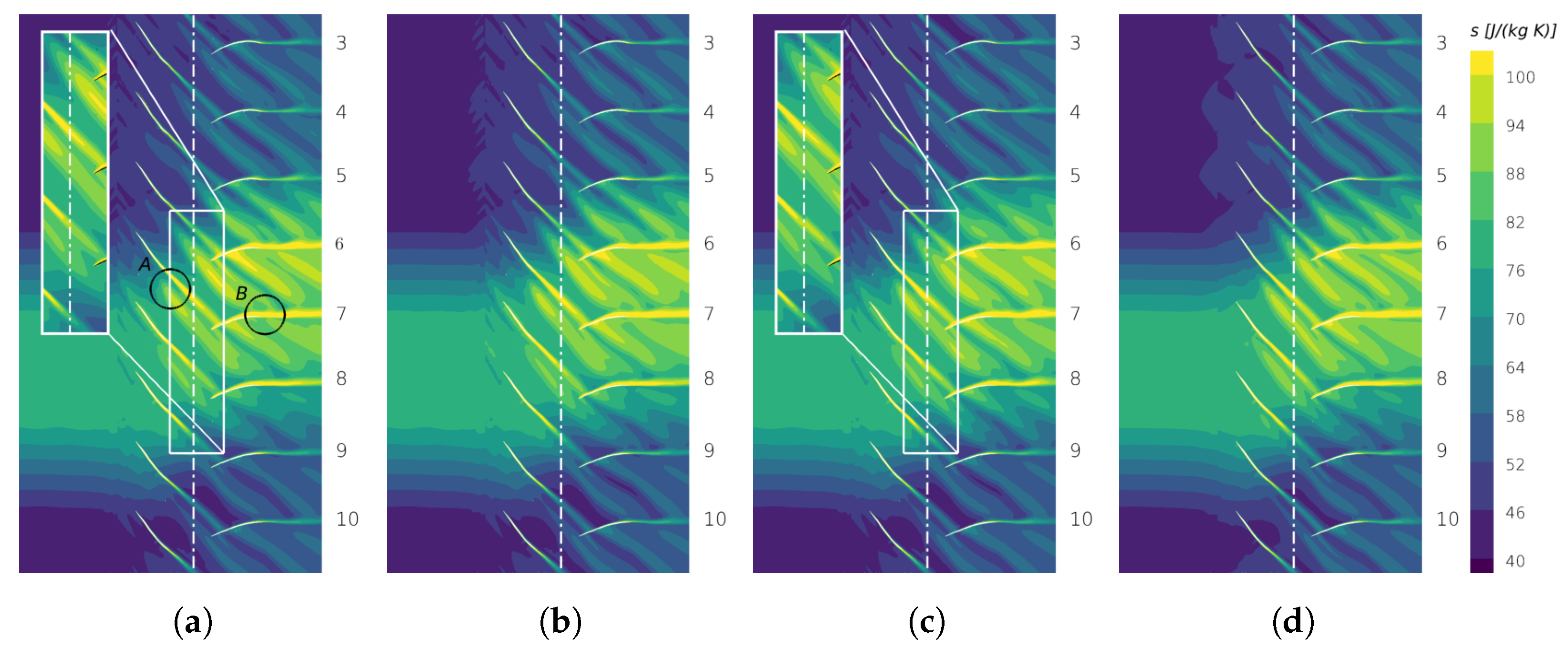
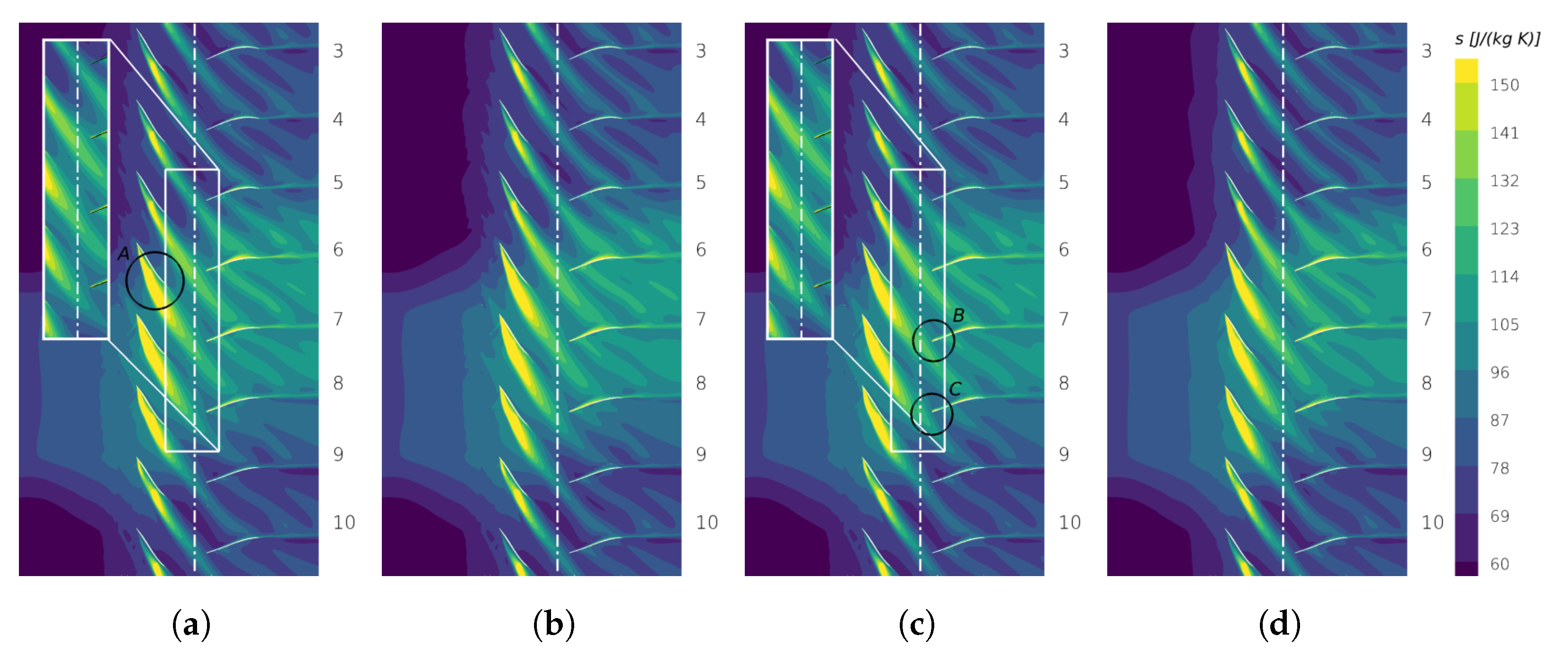
4.1. Instantaneous Entropy Distribution

In order to assess the capability of the different frequency-domain approaches to predict rotational asymmetric flow phenomena, Figure 4 shows the instantaneous entropy distribution for all frequency-domain approaches in a blade-to-blade cut at ~ 90 % relative radial height. This radial height represents a region where the total pressure deficit of the inlet distortion strongly interacts with the fan stage. Here, all frequency-domain simulations have been reconstructed in the time-domain and plotted on multiple passages in a post-processing step. An analysis of the impact of the modelling approach onto the prediction of the harmonic corresponding to the first fan blade passing frequency can be found in [24].
The inlet distortion modelling an ingested boundary layer enters the computational domain from the left. One can see that the total pressure deficit of the inlet distortion leads to increased entropy levels in this region. The distortion changes the ratio between total pressure and static pressure. This change in the static pressure also influences the static temperature and as a consequence the entropy. Furthermore, the velocity differences in the inlet distortion, generating a shearing in the flow that additionally generates entropy by dissipation.
One can see that the distorted flow convects through the intake and then interacts with the rotor row. Here, the distortion covers approximately four rotor blades in the circumferential direction. The increased profile loading on the blades, which interact with the inlet distortion, leads to an increased entropy production in the profile boundary layer. This leads to thicker wakes with increased entropy levels in comparison to the rotor blades in clean inflow far away from the area of influence of the inlet disturbance; cf. Figure 4a circle A. Comparing the results of all frequency-domain approaches, one can see that the interaction of the inlet distortion with the rotor blades and the thickening of the rotor wakes is equally well predicted in each approach, as is to be expected since the setups are identical across the intake and the rotor row; cf. Table 1. Special attention is therefore paid to the stator row, where the setups differ.
Figure 4a shows the frequency-domain simulation carried out with the MDFT approach on a single-passage stator domain, see Table 1 Case 1. One can see that the wakes of the rotor are continuously captured over the interface to the stator, cf. the marked white box. Furthermore, the inlet distortion itself as a rotational asymmetry in the flow is also perfectly captured. In the relative system of the stator, these thickened rotor wakes in the region of influence of the inlet distortion mainly interact with the stator blades 5–9. As a consequence of this interaction, the stator blades 5–9 also exhibit a thickening of their boundary layers and increased entropy levels in their wakes; cf. circle B. In contrast, the rotor blades 1–4 and 10–15 experience clean inflow conditions and therefore their wakes are thinner with lower entropy levels than in the region of disturbed inflow. The same can be applied to the stator blades in clean inflow.
If one qualitatively evaluates the entropy distribution over the fan stage computed with the MDFT approach, it can be stated that the approach is capable of capturing all relevant flow physics of the fan stage. First, the inlet distortion is accurately captured in the relative system of the stator, which represents the influence of the inlet distortion on the steady part of the flow, since in the relative system of the stator the inlet distortion is experienced as a steady disturbance. Second, the influence of the inlet distortion on the unsteady part of the flow is also accurately captured. To explain this in more detail, note that in the relative system of the stator, the wakes of the rotor are captured as unsteady disturbances with the blade passing frequency of the rotor ω R and an interblade phase angle of zero. In the region of influence of the inlet distortion, the disturbed inflow interacts with the rotor blades leading to an amplified entropy production in the rotor profile boundary layers, and as a consequence, to thickened rotor wakes. These thickened wakes in the region of disturbed inflow then lead to a circumferentially varying unsteady flow. In the relative system of the stator, this rotational asymmetry is captured with the blade passing frequency of the rotor ω R and non-zero interblade phase angle. Comparing the results of the MDFT approach with the results of the time-domain approach, as in Figure 4d, one can see that the thickening of the rotor wakes in the region of influence of the inlet distortion is accurately predicted. Additionally, the further convection of the thickened wakes into the relative system of the stator is also captured, confirming that the MDFT approach is able to account for the influence of the inlet distortion on the unsteady part of the flow.
To further validate the results of the MDFT approach, Figure 4b shows the simulation carried out with a standard DFT on a full annulus stator domain; see Table 1 Case 2. Comparing the stator rows in Figure 4a,b, one can see that the MDFT approach captures the interaction of the inlet distortion with the rotor wakes and its interaction with the stator blades with excellent agreement to the full annulus DFT. In particular, the computed position of the wakes, as well as their interactions with the inlet distortion, are almost identical in both approaches.
Alongside these two approaches, Figure 4c depicts the simulation carried out with the harmonic set approach on a single-passage stator domain, shown in Table 1 Case 3. In the relative system of the stator, the harmonic set approach neglects the influence of indexing on the propagation of the unsteady disturbances. More precisely, the harmonics of the rotor’s blade passing frequency ω R experience the same mean flow with every blade passage. Therefore, the harmonic set simulation exhibits differences in the relative system of the stator in comparison to the MDFT approach and the simulation based on a full annulus DFT. As already discussed, the inlet distortion interacts with the rotor wakes, which results in thicker wakes with increased entropy levels. In the intrarow gap, where the flow passes from the moving system of the rotor to the stationary system of the stator, one can see within the marked white box that those thickened wakes in the region of influence of the inlet distortion are not continuously resolved over the interface. The wakes are positioned at different axial positions leading to offsets in the contour levels at the interface. Directly downstream of the interface in the relative system of the stator, the entropy levels of the wakes in the region of influence of the inlet distortion abruptly drop to a lower level. Evaluating the further propagation of the wakes in the downstream direction, one can see that the wakes are located at different axial positions in comparison to the other frequency-domain approaches. Since the inlet distortion strongly interacts with the unsteady flow field in the rotor, leading to a circumferentially varying unsteady flow, the ability to resolve the thickened wakes at their correct axial and circumferential positions with the right entropy levels is connected to the ability of an approach to capture the influence of indexing on the unsteady part of the flow. This interaction is, however, neglected in the harmonic set approach.
Examining the entropy field computed with the harmonic set approach far away from the region of influence of the inlet disturbance, one can see that the convection of the rotor wakes at the interface and their propagation downstream is accurately captured. This emphasises that in regions where only a minor interaction of the inlet distortion with the unsteady flow occurs, the harmonic set approach provides good results on a computationally attractive single-passage domain. Due to the assumptions of the harmonic set approach, major deviations are only to be expected where a strong nonlinear interaction between harmonic sets may occur, e.g., the unsteady interaction between an inlet distortion and downstream blades and their wakes. Therefore, for such flow phenomena advanced methodologies such as the MDFT approach or the full annulus DFT are recommended.
Figure 5 shows the instantaneous entropy distribution for all approaches in a blade-to-blade cut at ~ 95 % relative radial height. This height is of special interest, since here the interaction of the rotor’s tip leakage vortex with the inlet distortion and its further propagation and interaction with the stator can be evaluated in detail. The tip leakage vortex is generated in the constructional rotor tip gap, where the pressure difference between the two sides of the blade generates a fluid motion over the rotor’s tip from the pressure side to the suction side. This tip leakage flow then interacts with the main flow in the passage and with other secondary flow phenomena, and finally, rolls up into a spiral vortex. The further interaction of such vortices with other incoming unsteady disturbances generates a highly three-dimensional flow field. In the present testcase, the tip leakage vortices within the region of influence of the inlet distortion interact with the distorted inflow, while other blades experience clean inflow conditions depending on the relative circumferential position of each respective blade to the inlet distortion. In Figure 5a, one can identify the tip leakage vortices as local regions with increased entropy levels along the suction side of the rotor’s blades, which also extend over the rotor’s passages. In particular, the entropy rise becomes even stronger in regions where the tip leakage vortices interact with the inlet distortion, as seen in circle A, whilst far away from the region of influence of the inlet distortion, the entropy levels in the vortices are much lower. This highlights that the inlet distortion has a significant negative influence on the tip leakage vortices, since the inlet distortion strengthens the tip leakage vortices, and thereby amplifies the losses. In the regions behind the trailing edges of the rotor’s blades, the tip leakage vortices unify with the wakes of the rotor. One can see that the MDFT approach properly captures the further propagation of the tip leakage vortices unified with the wakes into the relative system of the stator. The contour lines are continuous over the interface, as seen in the marked white box, and the interaction with the downstream stator is captured accurately compared to the unsteady time-domain simulation.
Comparing the results of the single-passage MDFT approach with the simulation based on a full annulus standard DFT, as in Figure 5b, one can see that both simulations show very good agreement with each other. This further highlights that the MDFT approach has been successfully extended to account for rotationally asymmetric flow phenomena, such as the interaction of tip leakage vortices with distorted inflow, on a single passage domain. In contrast, in the simulation based on the harmonic set concept, seen in Figure 5c, the tip leakage vortices unified with the wakes of the rotor exhibit entropy offsets at the interface to the stator, which are marked with the white box, leading to discontinuous contour lines over the interface. Furthermore, in the relative system of the stator, the axial position of the vortex is predicted to be further downstream. For example, for the stator blades 7 and 8, circles B and C, the vortices unified with the wakes are closer to the leading edges of the blades as in the simulations carried out with the MDFT approach or the standard DFT. This highlights that important parts of the unsteady flow physics are unresolved if the influence of indexing on the unsteady part of the flow is neglected.

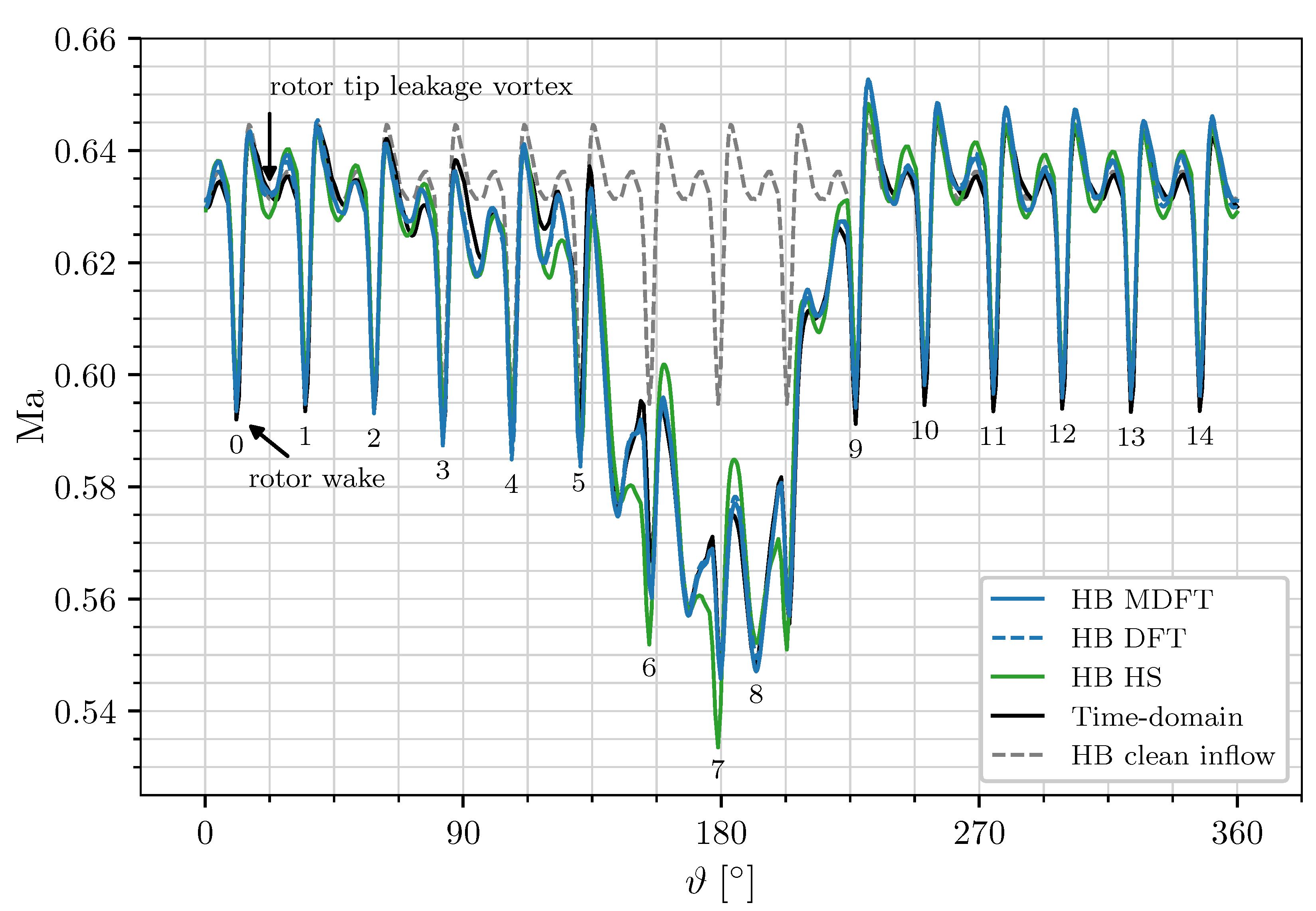
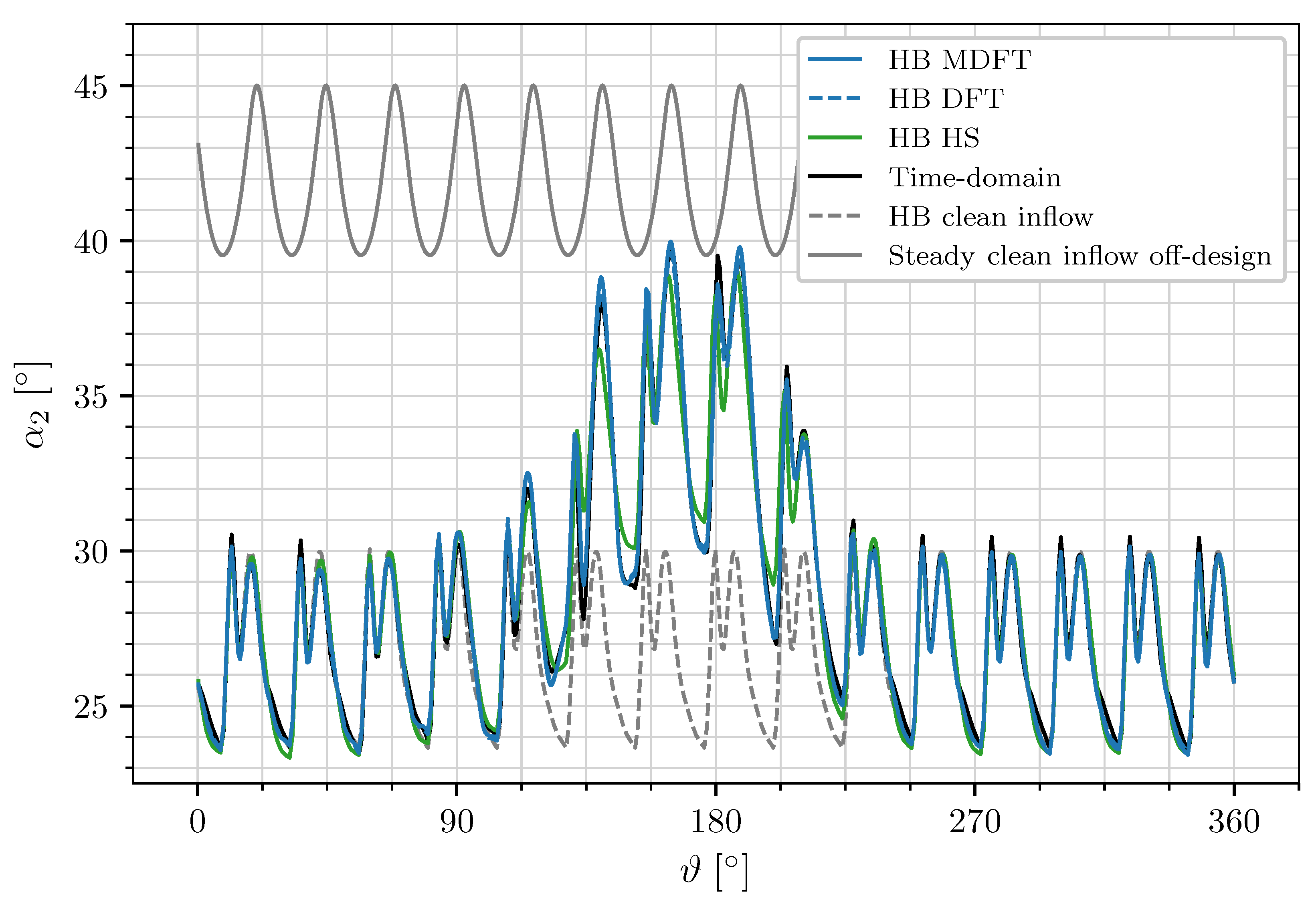
4.2. Analysis of the Flow in Front of the Stator

Figure 6 shows the entropy distribution over the full radius and circumference of all frequency- and time-domain approaches in front of the stator at slice position A. In all approaches, one can see the 15 wakes of the 15 rotor blades at the enumerated positions characterised by the thin areas with increased entropy levels from hub to tip. Due to the relative rotational motion between rotor and stator, the rotor wakes exhibit a curved bend over the radial height. Furthermore, one can see that the inlet distortion generates an area of increased entropy in the lower part of the annulus between blades 5 and 9. Since the rotor in front of the stator is moving counterclockwise, the region of influence of the distortion with increased entropy is also shifted counterclockwise. Observe that the blades 6–8, especially, are in the strongest region of influence of the inlet distortion and therefore experience an increased profile loading in comparison to the rotor blades with clean inflow. Furthermore, the inlet distortion increases the entropy production in the tip leakage vortices, which is also visible in Figure 6. In the tip region between the blades 5–9 (see for example, in Figure 6a the red circle between blade 6 and 7) one can identify tip leakage vortices in distorted flow with a strong circular rotating entropy rise, which is more prominent than the entropy rise of the tip leakage vortices of blades 1–5 and 9–15 in clean inflow (see for example, the red circle between blade 13 and 14). As a consequence of this entropy rise, one may expect higher losses in regions where the inlet distortion interacts with the tip leakage vortices.
Comparing the results of the MDFT approach with the full annulus DFT, as in Figure 6a,c, one can see that the key flow physics discussed above are captured almost identically in both approaches. Comparing both simulations with the results computed with the harmonic set approach, as in Figure 6b, one can see that the harmonic set approach is also able to capture the interaction of inlet distortion with the rotor wakes, but with a slightly different entropy distribution in certain passages. In the region marked by the red circle between blade 4 and 6, the entropy levels are overestimated by the harmonic set approach in comparison with the MDFT and the standard DFT approaches. Furthermore, in the region of influence of the inlet distortion, blades 5–9, the contour levels computed with the harmonic set approach are nearly continuous from blade to blade, whilst the MDFT and the standard DFT approaches exhibit a rather step-like course from blade to blade. Comparing all frequency-domain approaches to the unsteady time-domain simulation, seen in Figure 6d, one can see that the single-passage MDFT as well as the standard DFT approaches both lead to very good agreement with the unsteady time-domain simulation, whilst the harmonic set approach exhibits the previously discussed overestimated entropy levels in certain passages.
To evaluate the differences in the flow solutions of all unsteady approaches resolving the inlet distortion quantitatively, Figure 7 shows the Mach number over the circumference at ~ 90 % relative radial height and slice position A; cf. Figure 6. Additionally, the harmonic balance simulation without an inlet distortion, Table 1 Case 6, is depicted for the same slice position and radial height. One can see that in regions of clean inflow, 0–90° and 225–360°, the Mach number oscillates nearly periodically. The trends in the simulations with an inlet distortion are here almost identical to the harmonic balance simulation with a uniform inflow. The periodic decreases in the Mach number mark the wakes of the 15 rotor blades, which develop from the viscous boundary layers of the blades and therefore exhibit a velocity deficit with a higher turbulence level in the region behind the trailing edge of each blade. Furthermore, there exists weaker Mach number drops, each on the right side of the stronger drop, which are induced by the tip leakage vortices of the rotor. In the region of disturbed inflow, 90–225°, the Mach number drops abruptly to a lower level and exhibits rather chaotic oscillations in comparison to the periodic behaviour of the harmonic balance simulation with clean inflow conditions in the same region. The chaotic oscillations are induced by the unsteady interaction of the inlet distortion with the rotor’s wakes and tip leakage vortices. Observe that in the region of distorted flow, the Mach number variations due to the wakes are indistinguishable from the Mach number variations due to the tip leakage vortices, whereas in regions of clean inflow both effects are clearly separable.
Comparing the different approaches, one can see that the single-passage MDFT simulation is in very good agreement with the full annulus stator simulation based on a standard DFT. Furthermore, both simulations lead to good agreement with the unsteady time-domain simulation. In contrast, the simulation based on the harmonic set approach shows a deviating course of the Mach number in comparison to the other two frequency-domain approaches, most prominent in the regions of the distorted inflow. As already discussed, the harmonic set approach neglects the influence of the inlet distortion on the unsteady part of flow. The previous results have already shown shifted wakes with deviating entropy levels. This effect is also visible in the Mach number course over the circumference. In regions of distorted inflow, the positions of the Mach number minima are slightly shifted and the amplitudes are either over- or underestimated in comparison to the other two frequency-domain approaches with the distorted inflow.
So far, it has been shown that inlet distortions induce a significant variation in the flow characteristics from passage to passage. However, in conventional turbomachinery blading design, this variation is not taken into account. To highlight that the MDFT method provides added value in predicting circumferentially varying flow conditions, Figure 8 depicts for all unsteady approaches the inflow angle α 2 according to [25] over the circumference at ~ 90 % relative radial height and slice position A. Alongside the results with distorted inflow, the harmonic balance simulation with clean inflow conditions is also depicted. One can see that in regions of distorted flow, the inflow angle α 2 increases by up to 10 , whilst in regions of clean inflow the angles of all approaches with distorted inflow are very close to the angles predicted by the harmonic balance simulation without an inlet distortion. From this, it follows that Figure 8 implicitly shows the distribution of the incidence angle given by the difference of the inflow angles between the unsteady simulations with disturbed and undisturbed inflow. Note that the inflow angle of the simulation with clean inflow is here assumed to match the blade’s inlet angle. One can see that the inflow angle increases in the distorted inflow α 2 , d i s t o r t e d > α 2 , c l e a n , which leads to increased incidence and hence increased profile loading and a higher deflection of the stator blades in the distorted inflow. Comparing the different unsteady approaches, one can see that the MDFT, as well as the simulation based on a standard DFT, exhibits very good agreement with the unsteady time-domain simulation, whilst the simulation based on the harmonic set concept either over- or underestimates the inflow angle in the region of influence of the inlet distortion. In contrast, in passages with clean inflow, the harmonic set approach predicts the inflow angle accurately.
The results so far have shown that the inlet distortion significantly influences the inflow angle of certain stator blades. However, with regard to conventional turbomachinery design, the stator has been designed with a steady mixing plane approach and clean inflow conditions. Therefore, for turbomachinery designers it is of special interest to verify if the present design under perturbed inflow conditions is located within the original design space predicted by a steady approach and clean inflow. Since the most challenging flow conditions in compressors and fans appear close to surge conditions, Figure 8 also shows the inflow angle α 2 in off-design close to the surge margin predicted by a steady simulation in clean inflow. Observe that in numerical simulations the surge margin can only be approximated, since low mass flow rates and the high static pressure at the exit plane close to surge lead to numerical instabilities, which prevent the convergence of the operating point. Therefore, the last converged steady operating point in off-design is only close to surge. One can see that this off-design operating point in the clean inflow conditions exhibits higher inflow angles than the design operating point under the distorted inflow predicted by all unsteady approaches. From this, it follows that the inflow angle variation of the fan under the distorted inflow is still in the design scope of the original fan with homogeneous inflow at off-design operating conditions. Nevertheless, the inflow angle in the region of the distorted flow at the depicted design operating point is still close to the off-design inflow angle. This leads to the issue that the fan in the distorted inflow does not operate at its design conditions defined as the operating point with maximum efficiency. Furthermore, the prescribed inlet distortion in the form of a total pressure disturbance is rather weak. Therefore, in the case of a stronger inlet distortion, the fan may exceed its original design space.

4.3. Analysis of Fan Performance

To complete the evaluation of the fan stage, the operating behaviours of the engine under clean and distorted inflows are investigated. Figure 9 shows the full steady design characteristic at design speed without the inlet distortion. Note that the operating conditions of the point with maximum efficiency on the steady design characteristic have been used for all other simulations presented in the following. First, a reference harmonic balance simulation with clean inflow conditions (see the grey square) is depicted to evaluate the influence of an unsteady approach on the prediction of the design operating conditions in clean inflow. Since the overall variations in the design characteristic are small, detailed figures of the stagnation pressure ratio, as well as the ratio of the isentropic efficiency to the maximum isentropic efficiency, over the ISA-corrected reduced mass flow rate, are also provided. One can see that the harmonic balance simulation in the clean inflow predicts a nearly identical total pressure ratio in comparison with the steady clean inflow simulation. In contrast, a higher isentropic efficiency is predicted, which is due to the well-known effect of the steady mixing plane approach to overestimate mixing losses, since artificial mixing at interfaces produces mixing entropy [26].
Furthermore, for this operating point, steady and unsteady simulations under the distorted inflow are also depicted; cf. Table 1. Here, one can see that due to the reduced inflow velocity in the distorted area, the overall mass flow rate is reduced, while the stagnation pressure ratio rises due to an increased incidence angle; cf. [27]. For the same reason, the distorted inflow reduces the isentropic efficiency of the fan stage [15]. One can see that all unsteady approaches under the distorted inflow show a stronger drop in mass flow rate in comparison to the steady simulation under the distorted inflow with a mixing plane approach. Furthermore, all frequency-domain approaches predict a sightly lower total pressure ratio, but a higher isentropic efficiency than the steady simulation under the distorted inflow with the mixing plane approach, which is again due to the mixing plane approach overestimating mixing losses.
Comparing all frequency-domain approaches, one can see that all methods predict essentially identical values of total pressure ratio and isentropic efficiency. Moreover, the rise in the total pressure ratio and the drop in the efficiency predicted by the frequency-domain simulations are roughly the same as those obtained from the unsteady time-domain results. However, to predict local flow phenomena, such as the interaction of the inlet distortion with the blades and wakes, the capability of an approach to predict the effect of indexing on the unsteady part of the flow is of major importance.

4.4. Computational Costs

The results in this work show that the impact of the inlet distortion on the unsteadiness in the stator can be captured well with a standard harmonic balance approach on a full-annulus domain as well as on a single-passage domain when the MDFT harmonic balance method is used. Therefore, the question of CPU efficiency for these HB approaches, in comparison with a time-domain simulation, arises. As discussed in [24], the harmonic balance approaches are estimated to increase the speed between 1 and 2 orders of magnitude over time-integration methods. The CPU costs of the MDFT approach are, of course, proportional to the number of cells. However, a higher number of sampling points and more frequencies must be considered at the same time, which leads to a trade-off situation that depends on the number of stator positions necessary to resolve the asymmetry. A comprehensive analysis of this trade-off is beyond the scope of this publication, but can be found in [24]. In this thesis, it is shown that the computing time of the MDFT approach can be further reduced when a reduced number of passage indices and a reduced spectrum is considered, leading to results equivalent to the full spectrum simulation.

5. Conclusions

In this work, the harmonic balance approach using multidimensional time, recently introduced by the authors, has been extended to account for rotationally asymmetric flow on a single-passage domain. After a detailed introduction into the theory of the proposed extension, the method has been successfully applied to a modern low-pressure fan stage of a civil aero engine under the influence of an inhomogeneous, rotationally asymmetric inflow condition.
The evaluation of the results has shown that the MDFT approach is able to capture all relevant flow physics of this testcase. First, the inlet distortion is perfectly captured in the relative system of the stator, which represents the influence of the inlet distortion on the steady part of the flow. Second, the MDFT approach resolves the thickening of the rotor’s wakes and tip leakage vortices in the region of influence of the inlet distortion. Even more importantly, the further convection of both local flow phenomena into the relative system of the stator is perfectly captured, which validates that the MDFT approach has been successfully extended to account for the influence of the inlet distortion on the unsteady part of the flow. Comparing the results of the MDFT approach computed on a single-passage stator row with the reference frequency-domain simulation based on a standard DFT with a full annulus stator row, both approaches have shown almost identical simulation results. Furthermore, both approaches exhibit very good agreement to the unsteady time-domain simulation. Additionally, simulations with the harmonic set concept have been presented, which exhibited major differences to all other frequency- and time-domain approaches. It has been shown that the capability of resolving the thickened wakes at the right axial and circumferential positions with the correct entropy levels is connected to the capability of an approach to consider the influence of indexing on the unsteady part of the flow. However, this interaction exactly is neglected within the harmonic set approach, leading to the described differences to the other frequency- and time-domain approaches.
The inflow angle under distorted flow varied by multiple degrees, leading to increased incidence and hence increased profile loading and a higher deflection of the stator blades in distorted inflow. However, all simulation approaches with distorted inflow still exhibited smaller inflow and outflow angles than the angles within an off-design operating point near surge predicted by a steady mixing plane simulation with clean inflow. From this, it has been determined that the fan under distorted inflow is still in the design scope of the original fan in clean inflow, but it does not operate at its design conditions. Consequently, in the case of stronger inlet distortion, it might happen that the fan in distorted inflow exceeds its original design space, which highlights that unsteady approaches provide detailed insights into the unsteady flow field at off-design operating conditions.
To complete the evaluation of the fan with inlet distortion, design characteristics of all simulations with clean and distorted inflows have been computed and influence mechanisms of the ingested boundary layer have been evaluated. However, for average quantities such as the total pressure ratio and isentropic efficiency, it appears to be of secondary importance if the respective approach is capable of simulating the effect of indexing on the unsteady part of the flow. Nevertheless, if a detailed aerodynamic analysis of the unsteady flow field in the fan stage is required, it has been shown that only the frequency-domain approaches are capable of resolving this unsteady interaction, such as the MDFT approach or the full annulus DFT, which lead to simulation results that are comparable to the unsteady time-domain simulation.

Author Contributions

Conceptualization, L.J., C.F. and G.A.; software, L.J., C.F., G.A. and E.K.; investigation, L.J.; writing—original draft preparation, L.J.; writing—review and editing, L.J. and C.F.; project administration, G.A. All authors have read and agreed to the published version of the manuscript.

Funding

This research received no external funding.

Institutional Review Board Statement

Not applicable.

Informed Consent Statement

Not applicable.

Data Availability Statement

Data is contained within the article.

Conflicts of Interest

Author Laura Junge was employed by the company Leybold GmbH (Part of Atlas of Copco Group). The remaining authors declare that the research was conducted in the absence of any commercial or financial relationships that could be construed as a potential conflict of interest.

Nomenclature

BBlade count
iSquare root of 1
DFTDiscrete Fourier transform
HBHarmonic balance
HSHarmonic set
KHighest harmonic
K Set of harmonic indices
kHarmonic index
LNumber of passages
L Set of passage indices
lPassage index
Δ l Passage periodicity
MNumber of time dimensions
MaMach number
MDFTMultidimensional discrete Fourier transform
NNumber of sampling points
q Vector of conservative flow variables
R Flow residual
sEntropy
TPeriod
T Set of sampling points
tPhysical time, sampling point
x , r , ϑ Cylindrical coordinates
α Flow angle
Δ ϑ Pitch
σ Interblade phase angle value
τ , λ Hyperphase
ψ Prefactor of Fourier transform
Ω Rotational speed
ω Angular frequency
F 1 , F (Inverse) Fourier transform
S Set of frequencies and interblade phase angles
gcdGreatest common divisor
Re Real part of a complex quantity
^ Fourier coefficient
˜ Multidimensional quantity
m Base frequency index, time dimension index
b Base quantity

References

  1. He, L.; Ning, W. Efficient approach for analysis of unsteady viscous flows in turbomachines. AIAA J. 1998, 36, 2005–2012. [Google Scholar] [CrossRef]
  2. Vasanthakumar, P. Three Dimensional Frequency-Domain Solution Method for Unsteady Turbomachinery Flows. Ph.D. Thesis, Durham University, Durham, UK, 2003. [Google Scholar]
  3. Hall, K.C.; Thomas, J.P. Computation of Unsteady Nonlinear Flows in Cascades Using a Harmonic Balance Technique. AIAA J. 2002, 40, 879–886. [Google Scholar] [CrossRef]
  4. McMullen, M. The Application of Non-Linear Frequency Domain Methods to the Euler and Navier-Stokes Equations. Ph.D. Thesis, Stanford University, Stanford, CA, USA, 2003. [Google Scholar]
  5. Guedeney, T.; Gomar, A.; Gallard, F.; Sicot, F.; Dufour, G.; Puigt, G. Non-uniform Time Sampling for Multiple-frequency Harmonic Balance Computations. J. Comput. Phys. 2013, 236, 317–345. [Google Scholar] [CrossRef]
  6. Frey, C.; Ashcroft, G.; Kersken, H.P.; Voigt, C. A Harmonic Balance Technique For Multistage Turbomachinery Applications. In Proceedings of the ASME Turbo Expo 2014, Düsseldorf, Germany, 16–20 June 2014. GT2014-25230. [Google Scholar]
  7. Subramanian, V.; Custer, C.H.; Weiss, J.M.; Hall, K.C. Unsteady Simulation of a Two-Stage Cooled High Pressure Turbine Using an Efficient Non-Linear Harmonic Balance Method. In Proceedings of the ASME Turbo Expo 2013, San Antonio, TX, USA, 3–7 June 2013. GT2013-94574. [Google Scholar]
  8. Junge, L.; Frey, C.; Ashcroft, G.; Kügeler, E. A New Harmonic Balance Approach Using Multidimensional Time. J. Eng. Gas Turbines Power 2021, 143, 081007. [Google Scholar] [CrossRef]
  9. Frey, C.; Ashcroft, G.; Kersken, H.P.; Schönweitz, D.; Mennicken, M. Simulation of Indexing and Clocking with Harmonic Balance. Int. J. Turbomach. Propuls. Power 2018, 3, 1. [Google Scholar] [CrossRef]
  10. He, L.; Chen, T.; Wells, R.G.; Li, Y.S.; Ning, W. Analysis of Rotor-Rotor and Stator-Stator Interferences in Multi-Stage Turbomachines. J. Turbomach. 2002, 124, 564–571. [Google Scholar] [CrossRef]
  11. Frey, C.; Ashcroft, G.; Kersken, H.P.; Schönweitz, D.; Mennicken, M. Simulation of Indexing and Clocking with Harmonic Balance. In Proceedings of the 12th European Conference on Turbomachinery Fluid dynamics & Thermodynamics ETC12, Stockholm Sweden, 3–7 April 2017. [Google Scholar]
  12. Shannon, C. Communication in the Presence of Noise. Proc. IRE 1949, 37, 10–21. [Google Scholar] [CrossRef]
  13. Becker, K.; Heitkamp, K.; Kügeler, E. Recent Progress in a Hybrid-Grid CFD Solver for Turbomachinery Flows. In Proceedings of the Fifth European Conference on Computational Fluid Dynamics ECCOMAS CFD 2010, Lisbon, Portugal, 14–17 June 2010. [Google Scholar]
  14. Lengyel-Kampmann, T.; Otten, T.; Schmidt, T.; Nicke, E. Optimization of an Engine with a Gear Driven Counter Rotating Fan Part I: Fan Performance and Design. In Proceedings of the 22nd ISABE Conference, Phoenix, AZ, USA, 25–30 October 2015. [Google Scholar]
  15. Gunn, E.J.; Hall, C.A. Aerodynamics of Boundary Layer Ingesting Fans. In Proceedings of the ASME Turbo Expo 2014, Düsseldorf, Germany, 16–20 June 2014. Volume 1A: Aircraft Engine; Fans and Blowers, V01AT01A024. [Google Scholar]
  16. Kim, H.; Liou, M.S. Flow Simulation of N2B Hybrid Wing Body Configuration. In Proceedings of the 50th AIAA Aerospace Sciences Meeting including the New Horizons Forum and Aerospace Exposition, Nashville, TN, USA, 9–12 January 2012. [Google Scholar] [CrossRef]
  17. Plas, A.; Crichton, D.; Sargeant, M.; Hynes, T.; Greitzer, E.; Hall, C.; Madani, V. Performance of a Boundary Layer Ingesting (BLI) Propulsion System. In Proceedings of the 45th AIAA Aerospace Sciences Meeting and Exhibit, Reno, NV, USA, 8–11 January 2007. [Google Scholar] [CrossRef]
  18. Orszag, S.A. On the elimination of aliasing in finite-difference schemes by filtering high-wavenumber components. J. Atmos. Sci. 1971, 28, 1074. [Google Scholar] [CrossRef]
  19. Frey, C.; Ashcroft, G.; Kersken, H.P. Simulations of Unsteady Blade Row Interactions Using Linear and Non-Linear Frequency Domain Methods. In Proceedings of the ASME Turbo Expo 2015, Montreal, QC, Canada, 15–19 June 2015. [Google Scholar]
  20. Kersken, H.P.; Ashcroft, G.; Frey, C. Nonreflecting Boundary Conditions for Aeroelastic Analysis in Time And Frequency Domain 3D RANS Solver. In Proceedings of the ASME Turbo Expo 2014, Düsseldorf, Germany, 16–20 June 2014. GT2014-25499. [Google Scholar]
  21. Schlüß, D.; Frey, C. Time Domain Flutter Simulations of a Steam Turbine Stage Using Spectral 2D Non-Reflecting Boundary Conditions. In Proceedings of the 15th International Symposium on Unsteady Aerodynamics, Aeroacoustics & Aeroelasticity of Turbomachines (ISUAAAT15), Oxford, UK, 24–27 September 2018. [Google Scholar]
  22. Schlüß, D.; Frey, C. Time Domain Implementation of a Spectral Non-Reflecting Boundary Condition for Unsteady Turbomachinery Flows. In Proceedings of the 24th ISABE Conference, Canberra, Australia, 22–27 September 2019. [Google Scholar]
  23. Wilcox, D.C. Reassessment of the Scale-Determining Equation for Advanced Turbulence Models. AIAA J. 1988, 26, 1299–1310. [Google Scholar] [CrossRef]
  24. Junge, L.K. A New Harmonic Balance Approach Using Multidimensional Time. Ph.D. Thesis, Ruhr-Universität Bochum, Universitätsbibliothek, Bochum, Germany, 2023. [Google Scholar] [CrossRef]
  25. Cumpsty, N. Compressor Aerodynamics; Number Bd. 10 in Compressor Aerodynamics; Krieger Publishing Company: Malabar, FL, USA, 2004. [Google Scholar]
  26. Denton, J.D. The Calculation of Three-Dimensional Viscous Flow Through Multistage Turbomachines. J. Turbomach. 1992, 114, 18–26. [Google Scholar] [CrossRef]
  27. Fidalgo, V.J.; Hall, C.A.; Colin, Y. A Study of Fan-Distortion Interaction Within the NASA Rotor 67 Transonic Stage. J. Turbomach. 2012, 134, 051011. [Google Scholar] [CrossRef]
Figure 1. Passage indices for B S 1 / B S 2 = 2 / 5 correspond to real stator positions. (a) Sampling points. (b) Sampling phases.
Ijtpp 09 00017 g001
Figure 2. Fan with inlet distortion. (a) Distorted relative total pressure distribution on fan stage entry plane. (b) Full annulus setup of the fan stage.
Ijtpp 09 00017 g002
Figure 3. Unfolded bi-dimensional frequency–time domain. (a) Frequency interblade phase angle combinations. (b) Sampling point combinations.
Ijtpp 09 00017 g003
Figure 4. Instantaneous entropy distribution at 90 % relative radial height. (a) HB MDFT, (b) HB DFT, (c) HB HS, (d) time domain.
Ijtpp 09 00017 g004
Figure 5. Instantaneous entropy distribution at 95 % relative radial height. (a) HB MDFT, (b) HB DFT, (c) HB HS, (d) time domain.
Ijtpp 09 00017 g005
Figure 6. Instantaneous entropy distribution in front of the stator. (a) HB MDFT, (b) HB HS, (c) HB DFT, (d) time domain.
Ijtpp 09 00017 g006
Figure 7. Instantaneous Mach number over the circumference at 90 % relative radial height and slice position A.
Ijtpp 09 00017 g007
Figure 8. Instantaneous inflow angle over the circumference at 90 % relative radial height and slice position A.
Ijtpp 09 00017 g008
Figure 9. Performance map for design speed.
Ijtpp 09 00017 g009
Table 1. Geometry setup of fan with inlet distortion.
Ijtpp 09 00017 i001
Disclaimer/Publisher’s Note: The statements, opinions and data contained in all publications are solely those of the individual author(s) and contributor(s) and not of MDPI and/or the editor(s). MDPI and/or the editor(s) disclaim responsibility for any injury to people or property resulting from any ideas, methods, instructions or products referred to in the content.

