
Fractional-Order LCL Filters: Principle, Frequency Characteristics, and Their Analysis

1
College of Electrical Engineering, Guangxi University, Nanning 530004, China
2
College of Mechanical and Electrical and Quality Technology Engineering, Nanning University, Nanning 530200, China
3
Electric Power Research Institute of Guangxi Power Grid Corporation, Nanning 530023, China
*
Authors to whom correspondence should be addressed.
Fractal Fract. 2024, 8(1), 38; https://doi.org/10.3390/fractalfract8010038
Submission received: 3 December 2023
/
Revised: 26 December 2023
/
Accepted: 2 January 2024
/
Published: 5 January 2024
(This article belongs to the Special Issue Advance on the Fractal and Fractional Calculus in Electrical and Electronic Engineering)
Abstract
:The fractional-order LCL filter, composed of two fractional-order inductors and one fractional-order capacitor, is a novel fractional-order π-type circuit introduced in recent years. Based on mathematical modeling, this article comprehensively studies the principles and frequency characteristics of fractional-order LCL filters. Five critical properties are derived and rigorously demonstrated. One of the most significant findings is that we identify the necessary and sufficient condition for resonance in fractional-order LCL filters when the sum of the orders of the fractional-order inductors and the fractional-order capacitor is equal to 2, which provides a theoretical foundation for effectively avoiding resonance in fractional-order LCL filters. The correctness of our theoretical derivation and analysis was confirmed through digital simulations. This study reveals that fractional-order LCL filters exhibit more versatile operational characteristics than traditional integer-order LCL filters, paving the way for broader application prospects.
1. Introduction
The development of fractional calculus and the research on the implementation methods of fractional-order elements have opened up new approaches for the design, modeling, and analysis of circuits [1,2,3,4,5,6,7,8,9,10,11]. Fractional-order circuits have become an emerging interdisciplinary research area and have drawn much interest [5].
Fractional-order inductors and fractional-order capacitors [12,13] are the essential building elements of fractional-order circuits. The mathematical models of a fractional-order inductor and a fractional-order capacitor can be expressed as [6,7,8].
where L is the inductance of a fractional-order inductor, and C is the capacitance of a fractional-order inductor. and are the order of a fractional-order inductor and a fractional-order capacitor, respectively. and satisfy . Particularly, when and , a fractional-order inductor and a fractional-order capacitor are traditional inductors and capacitors, respectively. is the inductor voltage, is the inductor current, is the capacitor voltage, and is the capacitor current.
From (1), we know that in addition to the traditional parameter (such as L or C), the fractional-order element introduces an additional parameter, namely order, which makes the element and system more complex and more difficult to analyze, on the one hand, but, on the other hand, it increases the flexibility and degree of freedom and brings in immense versatility towards design and application. For more information about the operating characteristics of fractional-order inductors and fractional-order capacitors, please refer to [3,6,7,8,12,13].
In recent years, many realizations and fabrication methods of fractional-order inductors and fractional-order capacitors have been reported [14,15,16,17,18,19,20,21,22,23,24,25,26,27,28,29,30], and the orders of some capacitors, such as super-capacitors, were verified as possibly being much further away from 1 by experiments [27]. At the same time, fractional-order inductors and fractional-order capacitors have gradually been applied to various traditional integer-order circuits, and counterpart fractional-order circuits are constructed, such as fractional-order chaotic circuits [3], fractional-order sinusoidal oscillators [4], fractional-order RLC/RC/RL circuits [6,7,10,11], fractional-order power electronic converters [8,9,31,32,33,34,35,36], etc.
The traditional integer-order LCL filter [37,38,39], which consists of two inductors, L1 and L2, and one capacitor, C, is a pivotal circuit extensively utilized in power electronic converters, such as in a grid-connected inverter, as shown in Figure 1a.
Figure 1b displays the Bode plot of an integer-order LCL filter, where ωrp denotes resonant frequency. When ω < ωrp and ω > ωrp, the asymptotic slopes of the logarithmic magnitude-frequency characteristic curve of an integer-order LCL filter are −20 dB/dec and −60 dB/dec, respectively [39]. The integer-order LCL filter plays a key role in filtering high-order harmonics in the AC side voltage and improving the quality of the current injected into the grid [37,38,39]. Compared with L filters, integer-order LCL filters can achieve a better high-frequency harmonic attenuation effect. However, the integer-order LCL filter has an inherent resonant peak, which will destroy the stability of the system when the system is not designed and controlled properly [37,38,39].
A fractional-order capacitor is introduced to replace the integer-order capacitor in an integer-order LCL filter to form an LCαL filter [40]. Theoretical analysis and numerical simulations show that the LCαL filter provides a wider bandwidth to mitigate higher-order resonant frequencies than its integer-order counterpart. The circuit and mathematical model of a fractional-order LCL filter are preliminarily given in [41]. However, the detailed theoretical derivation and analysis of the frequency characteristics are missing.
This study employs Caputo’s fractional calculus [1] to investigate the mathematical modeling and frequency characteristic analysis of fractional-order LCL filters. The aim is to expand the LCL filters from the integer-order domain to the fractional-order domain, laying a theoretical groundwork for the engineering application of fractional-order LCL filters. The main contributions and originality of this research are summarized as follows:
- (1)
- This paper pioneered a method for the theoretical analysis of the frequency characteristics of fractional-order LCL filters, summarized their five critical properties, and systematically revealed their principles and frequency characteristics.
- (2)
- It is found that the necessary and sufficient condition for resonance in the magnitude-frequency characteristic curve of fractional-order LCL filters is that the sum of the orders of the fractional-order inductor and the fractional-order capacitor is equal to 2. This provides a theoretical basis for effectively avoiding resonance in fractional-order LCL filters.
- (3)
- This paper fills the gap in the research on the frequency characteristics of general fractional systems with -order (where ).
The rest of this paper is organized as follows: the circuit and mathematical models of a fractional-order LCL filter are given in Section 2. In Section 3, the frequency characteristics of a fractional-order LCL filter are studied in depth, and five important properties of a fractional-order LCL filter are systematically presented. In Section 4, digital simulations are performed to verify the correctness of the theoretical derivation and analysis. Finally, conclusions are drawn in Section 5.
2. The Circuit and Mathematical Models of a Fractional-Order LCL Filter
By introducing the fractional-order inductors and the fractional-order capacitor to replace the inductors and the capacitor in an integer-order LCL filter, respectively, the main circuit of a fractional-order LCL filter can be obtained, as shown in Figure 2a, where the fractional-order LCL filter is used for the AC side filtering of a grid-connected inverter. denotes the inductance of the input side fractional-order inductor in units of , and its order is ; denotes the inductance of the output side fractional-order inductor in units of , and its order is ; C denotes the capacitance of the fractional-order capacitor in units of , and its order is . All the value ranges of , , and are (0, 2). Obviously, a fractional-order LCL filter is the general form of an LCL filter, and an integer-order LCL filter is just the special case of a fractional-order LCL filter when . In addition, is the DC voltage provided by the renewable energy generation or energy storage unit; , , and are the input voltage, the output voltage, and the fractional-order capacitor’s terminal voltage of a fractional-order LCL filter, respectively. , , and are the input current, the output current, and the fractional-order capacitor’s current of a fractional-order LCL filter, respectively. When a fractional-order LCL filter is used for the AC side filtering of a grid-connected inverter, , , and are also known as the AC side voltage of the inverter, the power grid voltage, and the current injected into the grid, respectively.
According to the Kirchhoff voltage law and the Kirchhoff current law, the time domain mathematical model of a fractional-order LCL filter can be expressed as
By performing the Laplace transform on (2), the s-domain expression of a fractional-order LCL filter can be obtained as
According to (3), we obtain the model structure of a fractional-order LCL filter, as shown in Figure 2b.
According to (3) and Figure 2b, the output current expression of a fractional-order LCL filter can be obtained as
In order to simplify the analysis, let ; then, (4) can be simplified as
Generally, is regarded as the disturbance of the system, so the transfer function from the input voltage to the output current can be obtained; that is, the transfer function of a fractional-order LCL filter is
where
From (6), we know that a fractional-order LCL filter is a fractional-order system with order , where . Until now, no study has systematically introduced the frequency characteristics of such fractional-order systems.
According to (6), the frequency domain model of a fractional-order LCL filter can be expressed as
Substituting the Euler equation
into (8), the frequency domain expression of a fractional-order LCL filter can be further expressed as
Based on (9), the expressions of the magnitude-frequency characteristics and the phase-frequency characteristics of a fractional-order LCL filter can be obtained as
3. The Frequency Characteristics and Analysis of a Fractional-Order LCL Filter
3.1. The Resonance Characteristics of a Fractional-Order LCL Filter
In (10), when , since , with the angular frequency increasing from 0, the denominator of increases monotonically; that is, decreases monotonically. In this case, there is no resonance in the magnitude-frequency characteristics of a fractional-order LCL filter.
When , , let us define an intermediate variable
namely, .
Substituting the expression of into (10), we obtain
When the angular frequency satisfies
can be expressed as
According to (15), we know that when , due to , we have . This means that the magnitude-frequency characteristics of a fractional-order LCL filter exhibit a resonance peak at . Conversely, if the magnitude-frequency characteristics of a fractional-order LCL filter have a resonance peak when , that is, , it follows that must be satisfied. For ease of distinction, we denote the when as , which represents the resonant frequency.
From the above analysis, we discern that the fractional-order LCL filter possesses the following resonance property:
Property 1.
When , the necessary and sufficient condition for a fractional-order LCL filter to have a resonance peak is
Substituting into (12), the expression of the resonant frequency can be obtained as follows:
According to (17), we further obtain the following resonant frequency property of a fractional-order LCL filter:
Property 2.
When the magnitude-frequency characteristics of a fractional-order LCL filter have a resonant peak, that is, the condition of holds, the expression of the resonant frequency is . The resonant frequency is only determined by the values of , , and , and is independent of the order of the fractional-order inductors and the order of the fractional-order capacitor.
Property 1 reveals the condition for the existence of the resonance of a fractional-order LCL filter, essentially, and provides a straightforward criterion for determining whether a fractional-order LCL filter exhibits a resonant peak. For example, in traditional integer-order LCL filters, since both and are 1, that is, , their magnitude-frequency characteristics invariably exhibit a resonance peak, as illustrated in Figure 1b. Furthermore, Property 1 offers theoretical ground for effectively circumventing resonance in the design phase of a fractional-order LCL filter. When a fractional-order LCL filter manifests a resonance peak, it can readily lead to system instability [37,38,39]. For an integer-order LCL filter, additional passive or active dampers are commonly incorporated to eliminate resonance and enhance system stability against variations [37,38]. However, the former can incur additional losses, diminishing the attenuation capability of high-frequency harmonics, while the latter can complicate the design of the controller. In contrast, for a fractional-order LCL, we can effectively circumvent the resonance peak by judiciously selecting the order of fractional-order inductors and the fractional-order capacitor, such that , thereby fundamentally enhancing system stability without adding dampers.
3.2. The Corner Frequency and Logarithmic Magnitude-Frequency Characteristics of a Fractional-Order LCL Filter
To analyze the corner frequency of a fractional-order LCL filter, according to the value range of , the following two intermediate variables of angular frequency are defined.
Figure 3 shows the waveforms of in (18) and in (19). From Figure 3, we know that when , there is ; when , there is .
Substituting (18) and (19) into (10), the magnitude-frequency characteristics of a fractional-order LCL filter can be expressed as
where
(1) The analysis when
According to the value range of , (20) can be further expressed as
For the first formula of (22), when , , considering that always holds, so it can be simplified as
According to (23), the logarithmic magnitude-frequency characteristic and its asymptotic slope of a fractional-order LCL filter when can be obtained as
For the second formula of (22), when , . Additionally, considering that there is when , then . So, it can be simplified as
According to (26), the logarithmic magnitude-frequency characteristic and its asymptotic slope of a fractional-order LCL filter when can be obtained as
(2) The analysis when
When , according to the value range of angular frequency, (20) can be further expressed as
For the first formula of (29), when , , considering that always holds, it can be simplified as
According to (30), we obtain
For the second formula of (29), when , . Additionally, considering that there is when , then . So, it can be simplified as
According to (33), we obtain
(3) A summary of the corner frequency and logarithmic magnitude-frequency characteristic
Drawing from the aforementioned theoretical derivation, we can deduce that when , the corner frequency of the fractional-order LCL filter is , and when , the corner frequency is . and can be condensed into the following expression for the corner frequency.
Furthermore, to facilitate discussions, we define the frequency ranges as the low-frequency band for and the high-frequency band for . By comparing (30)–(35) with (23)–(28), we observe that the expressions for the magnitude-frequency characteristics of the fractional-order LCL filter are identical when (0, 0.5] ∪ [1.5, 2.5] ∪ [3.5, 4) and (0.5, 1.5) ∪ (2.5, 3.5). The primary distinction lies in their corner frequency expressions. In summary, the logarithmic magnitude-frequency characteristics of fractional-order LCL filters can be summarized as follows.
Property 3.
When , the asymptotic slope of the logarithmic magnitude-frequency characteristic in the low-frequency band of a fractional-order LCL filter is ; when , the asymptotic slope of the logarithmic magnitude-frequency characteristic in the high-frequency band is .
Property 3 is crucial for analyzing the filtering performance of fractional-order LCL filters. From Property 3, it can be observed that the asymptotic slope of the logarithmic magnitude-frequency characteristics of a fractional-order LCL filter in the low-frequency band is solely determined by the order of the fractional-order inductors and is independent of the order of the fractional-order capacitor; in the high-frequency band, the asymptotic slope is affected by both and . Considering that , we know that the asymptotic slope range of the logarithmic magnitude-frequency characteristics of a fractional-order LCL filter in the low-frequency band and high-frequency band is (0 dB/dec, −40 dB/dec) and (0 dB/dec, −120 dB/dec), respectively.
According to (36), we find that the corner frequency of a fractional-order LCL filter is not only affected by the values of , and but also related to the order of the fractional-order inductors and the order of the fractional-order capacitor. Additionally, when , there is , which means that the resonant frequency is equal to the corner frequency. In particular, when , according to (25), (28), and (36), we obtain the corner frequency of an integer-order LCL filter as , and the asymptotic slopes of the low-frequency and high-frequency bands are −20 dB/dec and −60 dB/dec, respectively.
3.3. The Phase-Frequency Characteristics of a Fractional-Order LCL Filter
It is known to all that for a complex number , the value range of is generally called the principal argument of , and there is
where .
From (37), the first term of (11) can be further expressed as
which means always holds when .
To facilitate the derivation, let the center frequency
then, the (11) can be further simplified as
When , considering the characteristics of the sin and cos functions, the following relationship always holds.
then, there is
Therefore, the phase-frequency characteristics of a fractional-order LCL filter when are
When , , so (40) can be further simplified as
According to (37), the second term in (42) can be further expressed as
By synthesizing (42) and (43), the phase-frequency characteristics of a fractional-order LCL filter when can be obtained as
Based on (42) and (43), the phase-frequency characteristics of a fractional-order LCL filter can be summarized as follows.
Property 4.
When , the phase of a fractional-order LCL filter is ; when , if , the phase is . If , the phase is .
According to Property 4, it can be observed that when , the phase of the fractional-order LCL filter is solely determined by the order of the fractional-order inductor, and it is independent of the order of the fractional-order capacitor. Conversely, when , the phase is influenced by both and .
3.4. The Phase Crossover Frequency and Gain Margin of a Fractional-Order LCL Filter
It is well known that the frequency at which the open-loop phase-frequency characteristic intersects the horizontal line is commonly referred to as the phase crossover frequency, denoted as . According to (40), we know that the intersection frequency should satisfy the following equation for a fractional-order LCL filter.
By solving (45), we obtain
Given that , we have , so the numerator of (46) satisfies . Considering the domains of and , the denominator of (46) satisfies , if and only if . This means the right side of (46) is greater than 0, indicating that (46) has a real number solution, implying the presence of a phase crossover frequency in the phase-frequency characteristic of a fractional-order LCL filter. To sum up, the phase crossover frequency characteristics of a fractional-order LCL filter can be summarized as follows.
Property 5.
If and only if , the phase-frequency characteristics of a fractional-order LCL filter has a phase crossover frequency , and the expression of is
In particular, when , there is ; that is, the phase crossover frequency is equal to the resonant frequency.
When , the gain margin of a fractional-order LCL filter and its logarithmic expression can be obtained as
3.5. The Gain Crossover Frequency and Phase Margin of a Fractional-Order LCL Filter
As is widely known, the frequency satisfies or is usually referred to as the phase crossover frequency. According to (10), we know that the gain crossover frequency of a fractional-order LCL filter should satisfy the following equation.
By sorting out Equation (50), we obtain
The above formula is a highly complex nonlinear equation, making it challenging to derive an analytical solution for the gain crossover frequency of a fractional-order LCL filter. In order to obtain the trend graph of the change in with the order of the fractional-order inductors and the order of the fractional-order capacitor, we successively used the fsolve function, the particle swarm optimization algorithm [42], and the differential evolution algorithm [43] to solve (49) based on MATLAB 2018a software, and we found that the differential evolution algorithm has the best solution effect and relatively stable results.
Figure 4 shows a change diagram of the digital solution of obtained by the differential evolution algorithm versus plane when . The main circuit parameters of a fractional-order LCL filter are as follows: , , .
From Figure 4, we observe that as the combination of and approaches , there is a notable increase in the value of . This is attributed to the presence of a resonance peak in the fractional-order LCL filter when , which makes the logarithmic magnitude-frequency characteristic curve cross the 0 dB line many times. This phenomenon will be further verified in the following digital simulations.
Additionally, according to Property 3 and Figure 4, we know the following:
(1) Except for the case of , as the order of the fractional-order inductors increases, the asymptotic slope of the logarithmic magnitude-frequency characteristic curve in the low-frequency band increases accordingly, and the gain crossover frequency decreases.
(2) Considering that the order of the fractional-order capacitor does not affect the low-frequency asymptotic slope of the logarithmic magnitude-frequency characteristic curve of a fractional-order LCL filter, altering the order does not alter the gain crossover frequency, except in the case of .
The formula for calculating the phase margin of a fractional-order LCL filter is the same as that of an integer-order LCL filter, namely
4. Simulation Results and Analysis
To validate the theoretical derivation, analyze the frequency characteristics of fractional-order LCL filters, and investigate the impact of the order of the fractional-order inductors and the fractional-order capacitor on these characteristics, a digital model of a fractional-order LCL filter is established and simulated using MATLAB software. The main circuit parameters of the fractional-order LCL filter are consistent with those in Figure 4, and the order of the fractional-order inductors and the fractional-order capacitor will be specified later.
4.1. The Frequency Characteristic Simulation Curves of a Fractional-Order LCL Filter
(1) The frequency characteristic curves when is constant and changes
Simulation condition I: Set the order of the fractional-order inductors to 0.8, 1.0, and 1.2, respectively. For each case, increase the order of the fractional-order capacitor from 0.6 to 1.4 in 0.2 intervals.
The Bode plots of a fractional-order LCL filter based on Simulation condition I, as shown in Figure 5, and the corresponding frequency characteristic indicators are summarized in Table 1. In this table, NaN indicates the absence of such indicators, and Inf denotes infinite indicators.
(2) The frequency characteristic curves when is constant and changes
Simulation condition II: Set the order of the fractional-order capacitor to 0.8, 1.0, and 1.2, respectively. For each case, increase the order of the fractional-order inductor from 0.6 to 1.4 in 0.2 intervals.
4.2. The Analysis of the Frequency Characteristics of a Fractional-Order LCL Filter
(1) When , for instance, the combinations of and are (0.8, 1.2), (1.0, 1.0), and (1.2, 0.8), the magnitude-frequency characteristic curves of these fractional-order LCL filters cross the 0 dB line multiple times and exhibit a resonance peak at the resonant frequency. Moreover, the phase-frequency characteristic curves make a jump of −180° at the resonant frequency. For example, when the combination of and is (0.8, 1.2), the phase-frequency characteristic curve makes a jump from −72° to −252°. Furthermore, it can be observed that the resonant frequency is solely determined by , and and is independent of and . In this scenario, the theoretically calculated resonant frequency is
and the measured resonant frequency from the curves is 28,867 rad/s. Obviously, these two frequencies are essentially identical, with the minor deviation attributable to the discrete points connected by the curve in the Bode plot. In conclusion, the correctness of Properties 1 and 2 is confirmed.
(2) In each subplot of Figure 5, when the order of the fractional-order inductors remains constant and the order of the fractional-order capacitor changes, the five logarithmic magnitude-frequency characteristic curves overlap in the low-frequency band and diverge in the high-frequency band. This suggests that the order of the fractional-order capacitor does not affect the logarithmic magnitude-frequency characteristics of a fractional-order LCL filter in the low-frequency band, but it does have an effect in the high-frequency band. The asymptotic slope of the logarithmic magnitude-frequency characteristic curve of a fractional-order LCL filter in the low-frequency band is , which is solely related to . For example, when is 0.8, 1.0, and 1.2, the theoretical low-frequency slopes calculated based on Property 3 are , , and , while the measured values from the curves are , , and , aligning with the theory.
Additionally, the asymptotic slope of the logarithmic magnitude-frequency characteristic curve in the high-frequency band is , which is influenced by and . For example, when the combinations of and are , , and , the theoretical high-frequency slopes are , , and , with the measured curve values being , , and , which demonstrates that the theoretical calculated values are consistent with the actual measured values, too.
In each subplot of Figure 6, when remains constant, and takes on different values, the slopes of the low-frequency and high-frequency bands of the five logarithmic magnitude-frequency characteristic curves differ, further indicating that the asymptotic slope of the logarithmic magnitude-frequency characteristics of a fractional-order LCL filter in the low-frequency band are solely determined by , while the asymptotic slope in the high-frequency band is influenced by and .
Furthermore, when , the corner frequency is calculated according to the first formula of (36); for example, when , the theoretically calculated and the measured corner frequencies are 28,868 rad/s and 28,867 rad/s, respectively, which are essentially equivalent. When , the corner frequency should be calculated according to the second formula of (36); for example, when the combinations of and are and , the theoretically calculated corner frequencies are 2,024,272 rad/s and 2487 rad/s. The corner frequencies derived from the curve are 2,024,102 rad/s and 2487 rad/s, respectively. This suggests that the theoretically calculated values align with the actual measurements.
To sum up, the correctness of Property 3 has been confirmed.
(3) In each subplot of Figure 5, when is constant and changes, if , the five phase-frequency characteristic curves overlap; if , they diverge. This indicates that solely influences the phase-frequency characteristics of a fractional-order LCL filter in the high-frequency band but not in the low-frequency band. The low-frequency phase follows the law. For example, when is 0.8, 1.0, and 1.2, the theoretically calculated and measured low-frequency phases are , , and , respectively. It can be observed that the low-frequency phase is solely determined by .
Additionally, when , the high-frequency phase follows the rule . For example, when the combinations of and are , , and , both the theoretically calculated and the measured high-frequency phases equal , , and , respectively. When , the high-frequency phase follows the rule . For example, when the combinations of and are , , and , the theoretically calculated and measured high-frequency phases match , , and , respectively. Overall, the correctness of Property 4 has been verified.
(4) The measured value of the phase crossover frequencies shown in Table 1 and Table 2 equals the theoretical value calculated by (47). For example, when the combinations of and are , , , and , the calculated and measured phase-crossing frequencies are equivalent, specifically 508,310 rad/s, 98,864 rad/s, 28,867 rad/s, and 107,916 rad/s, respectively. In conclusion, the correctness of Property 5 is confirmed.
(5) From Table 1 and Figure 5, it is evident that when remains constant, and varies, the gain crossover frequency remains relatively constant, except when . For example, when the combinations of and are and , the gain crossover frequencies are nearly identical, specifically 1334 rad/s and 1345 rad/s, respectively. Furthermore, when approaches 2, there is a resonance in the magnitude-frequency characteristics of a fractional-order LCL filter, resulting in a sudden increase in the gain crossover frequency. Similarly, Table 2 and Figure 6 show that when remains constant and varies, the gain crossover frequency gradually increases as decreases, except when . These simulation results generally align with the observations presented in Figure 5.
Overall, the theoretical derivation and analysis of the frequency characteristics of fractional-order LCL filters have been validated through digital simulations.
5. Conclusions
Building on the mathematical model of fractional-order LCL filters, this article deduces five critical properties of these filters, systematically analyzing and summarizing their working principles and frequency characteristics. The primary differences in frequency characteristics between integer-order LCL filters and fractional-order LCL filters are summarized in Table 3.
Compared with an integer-order LCL filter, since the extra parameters of and are included, although a fractional-order LCL filter is more complicated to analyze, it has many novel behaviors and a wider operating range, which brings great flexibility and advantages to the application. The research in this paper provides a theoretical basis for the design of fractional-order LCL filters. By appropriately selecting the values of and , it is possible to obtain fractional-order LCL filters that can better coordinate filtering performance and system stability. It is expected that fractional-order LCL filters will be applied to replace traditional integer-order LCL filters in power electronic systems, such as inverters and rectifiers, and to construct better-performing fractional-order power electronic systems.
Furthermore, the frequency characteristic analysis method of fractional-order LCL filters proposed in this paper fills the gap in the research on the frequency characteristics of general fractional systems with -order (where ) and has good theoretical significance.
Author Contributions
Conceptualization, J.X.; Methodology, J.X., E.Z. and X.L.; Software, E.Z., G.H. and X.M.; Validation, X.L. and X.M.; Formal analysis, W.L.; Investigation, J.X. and G.H.; Resources, G.H. and W.L.; Data curation, J.X. and E.Z.; Writing—original draft, J.X.; Writing—review & editing, X.L.; Supervision, X.L. All authors have read and agreed to the published version of the manuscript.
Funding
This research received no external funding.
Data Availability Statement
The original contributions presented in the study are included in the article, further inquiries can be directed to the corresponding authors.
Conflicts of Interest
Author Xuanren Meng was employed by the company Electric Power Research Institute of Guangxi Power Grid Corporation. The remaining authors declare that the research was conducted in the absence of any commercial or financial relationships that could be construed as a potential conflict of interest.
References
- Podlubny, I. Fractional Differential Equations; Academic: New York, NY, USA, 1999. [Google Scholar]
- Monje, C.A.; Chen, Y.; Vinagre, B.M.; Xue, D.; Feliu, V. Fractional-Order Systems and Controls: Fundamentals and Applications; Springer: London, UK, 2010. [Google Scholar]
- Petras, I. Fractional Calculus. In Fractional-Order Nonlinear Systems; Higher Education: Beijing, China, 2011. [Google Scholar]
- Radwan, A.G.; Soliman, A.M.; Elwakil, A.S. Design equations for fractional-order sinusoidal oscillators: Four practical circuit examples. Int. J. Circuit Theory Appl. 2008, 36, 473–492. [Google Scholar] [CrossRef]
- Elwakil, A.S. Fractional-order circuits and systems: An emerging interdisciplinary research area. IEEE Circuits Syst. Mag. 2010, 10, 40–50. [Google Scholar] [CrossRef]
- Radwan, A.G.; Salama, K.N. Fractional-order RC and RL circuits. Circuits Syst. Signal Process. 2012, 31, 1901–1915. [Google Scholar] [CrossRef]
- Radwan, A.G.; Fouda, M.E. Optimization of Fractional-Order RLC Filters. Circuits Syst. Signal Process. 2013, 32, 2097–2118. [Google Scholar] [CrossRef]
- Xu, J.; Li, X.; Meng, X.; Qin, J.; Liu, H. Modeling and analysis of a single-phase fractional-order voltage source pulse width modulation rectifier. J. Power Sources 2020, 479, 228821. [Google Scholar] [CrossRef]
- Xu, J.; Li, X.; Liu, H.; Meng, X. Fractional-order modeling and analysis of a Three-phase Voltage Source PWM Rectifier. IEEE Access 2020, 8, 13507–13515. [Google Scholar] [CrossRef]
- Freeborn, T.J.; Maundy, B.; Elwakil, A. Fractional resonance-based RLβCα filters. Math. Probl. Eng. 2013, 2013, 726721. [Google Scholar] [CrossRef]
- Diao, L.; Zhang, X.; Chen, D. Fractional-order multiple RL alpha C beta circuit. Acta Phys. Sin. 2014, 63, 038401. [Google Scholar] [CrossRef]
- Westerlund, S.; Ekstam, L. Capacitor theory. IEEE Trans. Dielectr. Elect. Insul. 1994, 1, 826–839. [Google Scholar] [CrossRef]
- Westerlund, S. Dead Matter Has Memory; Causal Consulting: Kalmar, Sweden, 2002. [Google Scholar]
- Valsa, J.; Vlach, J. RC models of a constant phase element. Int. J. Circuit Theory Appl. 2013, 41, 59–67. [Google Scholar] [CrossRef]
- Sarafraz, M.S.; Tavazoei, M.S. Passive realization of fractional-order impedances by a fractional element and RLC components: Conditions and procedure. IEEE Trans. Circuits Syst. I Reg. Pap. 2017, 64, 585–595. [Google Scholar] [CrossRef]
- Semary, M.S.; Fouda, M.E.; Hassan, H.N.; Radwan, A.G. Realization of fractional-order capacitor based on passive symmetric network. J. Adv. Res. 2019, 18, 147–159. [Google Scholar] [CrossRef]
- Tsirimokou, G.; Psychalinos, C.; Elwakil, A.S. Emulation of a constant phase element using operational transconductance amplifiers. Analog Integr. Circuits Signal Process. 2015, 85, 413–423. [Google Scholar] [CrossRef]
- Bertsias, P.; Psychalinos, C.; Radwan, A.G.; Elwakil, A.S. High-Frequency Capacitorless Fractional-Order CPE and FI Emulator. Circuits Syst. Signal Process. 2018, 37, 2694–2713. [Google Scholar] [CrossRef]
- Jiang, Y.; Zhang, B. High-Power Fractional-Order Capacitor With 1 < alpha < 2 Based on Power Converter. IEEE Trans. Ind. Electron. 2018, 65, 3157–3164. [Google Scholar]
- Kapoulea, S.; Psychalinos, C.; Elwakil, A.S.; Radwan, A.G. One-terminal electronically controlled fractional-order capacitor and inductor emulator. AEU-Int. J. Electron. Commun. 2019, 103, 32–45. [Google Scholar] [CrossRef]
- Jesus, I.S.; Machado, J.A.T. Development of fractional order capacitors based on electrolyte processes. Nonlinear Dyn. 2009, 56, 45–55. [Google Scholar] [CrossRef]
- Krishna, M.S.; Das, S.; Biswas, K.; Goswami, B. Fabrication of a fractional order capacitor with desired specifications: A study on process identification and characterization. IEEE Trans. Electron Devices 2011, 58, 4067–4073. [Google Scholar] [CrossRef]
- Haba, T.C.; Ablart, G.; Camps, T.; Olivie, F. Influence of the electrical parameters on the input impedance of a fractal structure realised on silicon. Chaos Solitons Fractals 2005, 24, 479–490. [Google Scholar] [CrossRef]
- Mondal, D.; Biswas, K. Packaging of single-component fractional order element. IEEE Trans. Device Mater. Reliab. 2013, 13, 73–80. [Google Scholar] [CrossRef]
- Agambayev, A.; Patole, S.P.; Farhat, M.; Elwakil, A.; Bagci, H.; Salama, K.N. Ferroelectric fractional-order capacitors. ChemElectroChem 2017, 4, 2807–2813. [Google Scholar] [CrossRef]
- Agambayev, A.; Patole, S.; Bagci, H.; Salama, K.N. Tunable fractional-order capacitor using layered ferroelectric polymers. AIP Adv. 2017, 7, 095202. [Google Scholar] [CrossRef]
- Freeborn, T.J.; Maundy, B.; Elwakil, A.S. Measurement of supercapacitor fractional-order model parameters from voltage-excited step response. IEEE J. Emerg. Sel. Top. Circuits Syst. 2013, 3, 367–376. [Google Scholar] [CrossRef]
- Machado, J.A.T.; Galhano, A.M.S.F. Fractional order inductive phenomena based on the skin effect. Nonlinear Dyn. 2012, 68, 107–115. [Google Scholar] [CrossRef]
- Tripathy, M.C.; Mondal, D.; Biswas, K.; Sen, S. Experimental studies on realization of fractional inductors and fractional-order bandpass filters. Int. J. Circuit Theory Appl. 2015, 43, 1183–1196. [Google Scholar] [CrossRef]
- Adhikary, A.; Choudhary, S.; Sen, S. Optimal design for realizing a grounded fractional order inductor using GIC. IEEE Trans. Circuits Syst. I Reg. Pap. 2018, 65, 2411–2421. [Google Scholar] [CrossRef]
- Wang, F.; Ma, X. Transfer function modeling and analysis of the open-loop buck converter using the fractional calculus. Chin. Phys. B 2013, 22, 030506. [Google Scholar] [CrossRef]
- Wang, F.; Ma, X. Modeling and Analysis of the Fractional Order Buck Converter in DCM Operation by using Fractional Calculus and the Circuit-Averaging Technique. J. Power Electron. 2013, 13, 1008–1015. [Google Scholar] [CrossRef]
- Wei, Z.; Zhang, B.; Jiang, Y. Analysis and Modeling of Fractional-Order Buck Converter Based on Riemann-Liouville Derivative. IEEE Access 2019, 7, 162768–162777. [Google Scholar] [CrossRef]
- Tan, C.; Liang, Z. Modeling and simulation analysis of fractional-order Boost converter in pseudo-continuous conduction mode. Acta Phys. Sin. 2014, 63, 070502. [Google Scholar]
- Yang, N.; Liu, C.; Wu, C. Modeling and dynamics analysis of the fractional-order Buck-Boost converter in continuous conduction mode. Chin. Phys. B 2012, 21, 080503. [Google Scholar] [CrossRef]
- Chen, X.; Chen, Y.; Zhang, B.; Qiu, D. A Modeling and Analysis Method for Fractional-Order DC-DC Converters. IEEE Trans. Power Electron. 2017, 32, 7034–7044. [Google Scholar] [CrossRef]
- Twining, E.; Holmes, D.G. Grid current regulation of a three-phase voltage source inverter with an LCL input filter. IEEE Trans. Power Electron. 2003, 18, 888–895. [Google Scholar] [CrossRef]
- Wang, X.; Ruan, X.; Liu, S.; Tse, C.K. Full feedforward of grid voltage for grid-connected inverter with LCL filter to suppress current distortion due to grid voltage harmonics. IEEE Trans. Power Electron. 2010, 25, 3119–3127. [Google Scholar] [CrossRef]
- Wu, W.; He, Y.; Tang, T.; Blaabjerg, F. A New Design Method for the Passive Damped LCL and LLCL Filter-Based Single-Phase Grid-Tied Inverter. IEEE Trans. Ind. Electron. 2013, 60, 4339–4350. [Google Scholar] [CrossRef]
- El-Khazali, R. Fractional-Order LCαL Filter-Based Grid Connected PV Systems. In Proceedings of the 2019 IEEE 62nd International Midwest Symposium on Circuits and Systems (MWSCAS), Dallas, TX, USA, 4–7 August 2019; pp. 533–536. [Google Scholar]
- Sun, E. Modeling and Simulation of Fractional Active Power Filter. Master’s Thesis, School of Electrical Engineering, Dalian University of Technology, Dalian, China, 2017. (In Chinese with English abstract). [Google Scholar]
- Kennedy, J.; Eberhart, R. Particle swarm optimization. In Proceedings of the IEEE International Conference on Neural Networks, Perth, Australia, 27 November–1 December 1995; Volume 4, pp. 1942–1948. [Google Scholar]
- Price, K.V.; Storn, R. Differential evolution: A simple evolution strategy for fast optimization. Dr. Dobb’s J. 1997, 22, 18–24. [Google Scholar]
Figure 1.
The main circuit topology and Bode plot of an integer-order LCL filter. (a) A grid-connected inverter with an integer-order LCL filter. (b) The Bode plot of an integer-order LCL filter.
Figure 1.
The main circuit topology and Bode plot of an integer-order LCL filter. (a) A grid-connected inverter with an integer-order LCL filter. (b) The Bode plot of an integer-order LCL filter.
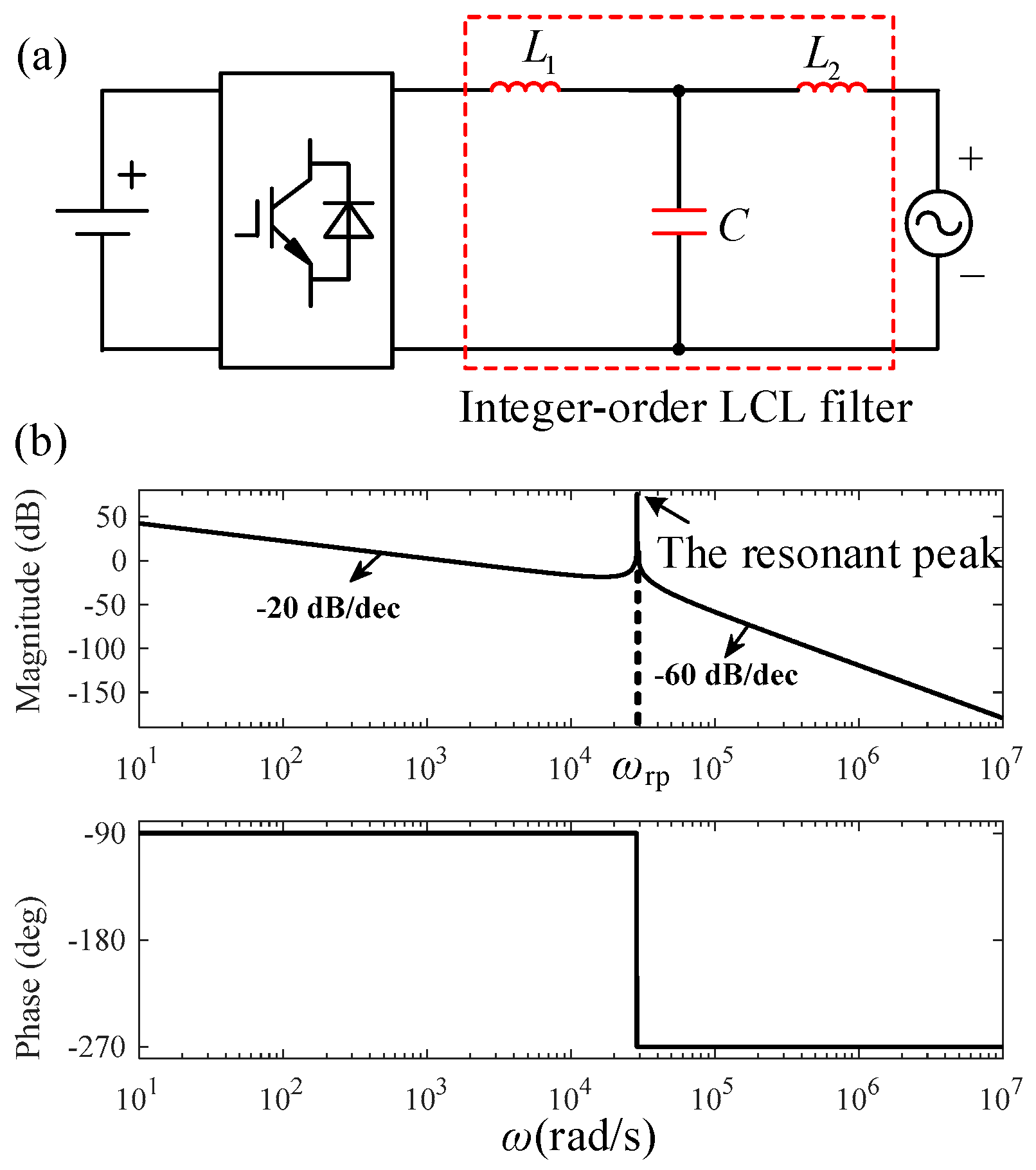
Figure 2.
The main circuit topology and the model structure of a fractional-order LCL filter. (a) The main circuit topology of a fractional-order LCL filter. (b) The model structure of a fractional-order LCL filter.
Figure 2.
The main circuit topology and the model structure of a fractional-order LCL filter. (a) The main circuit topology of a fractional-order LCL filter. (b) The model structure of a fractional-order LCL filter.
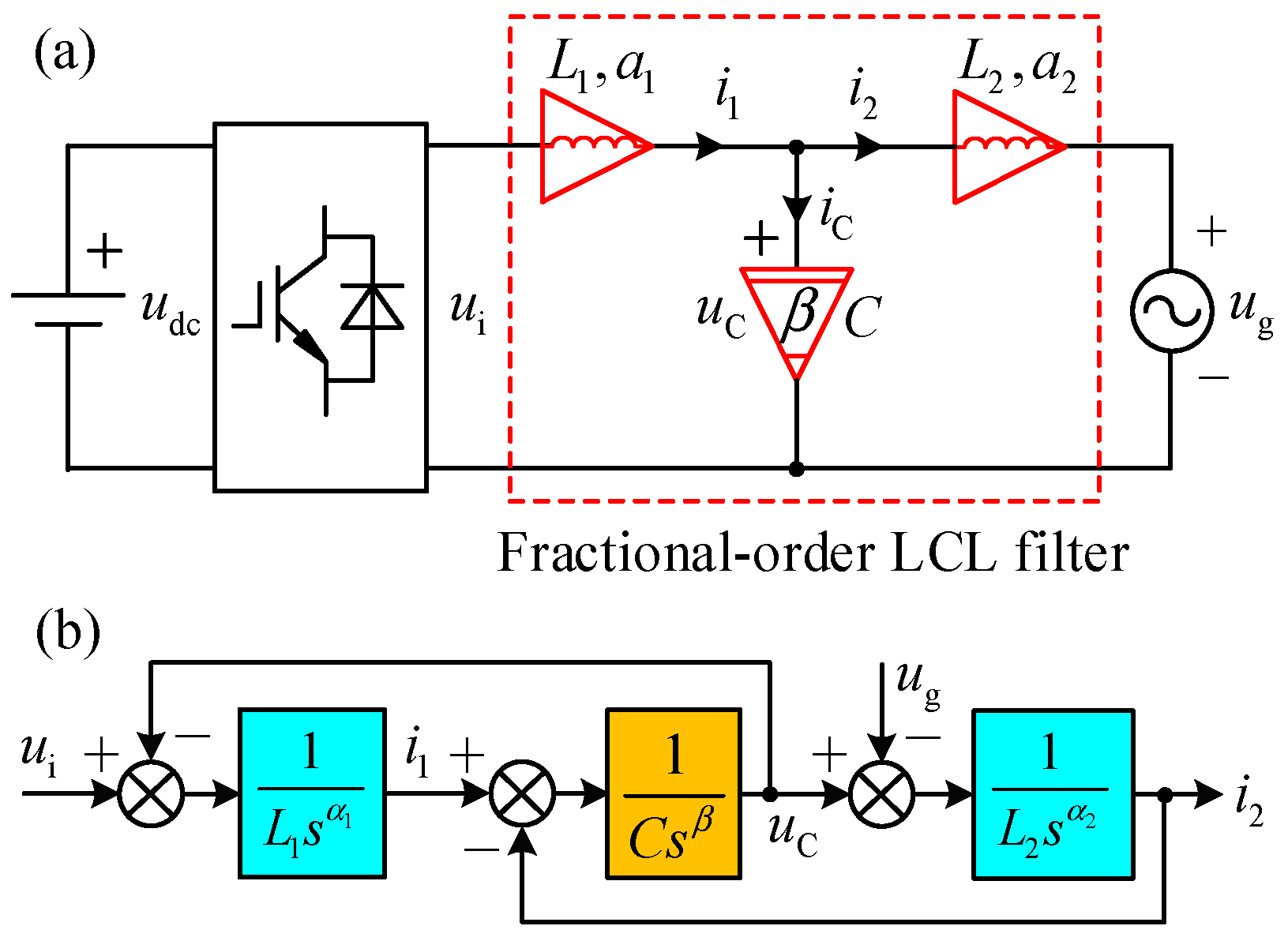
Figure 3.
The waveforms of and versus .
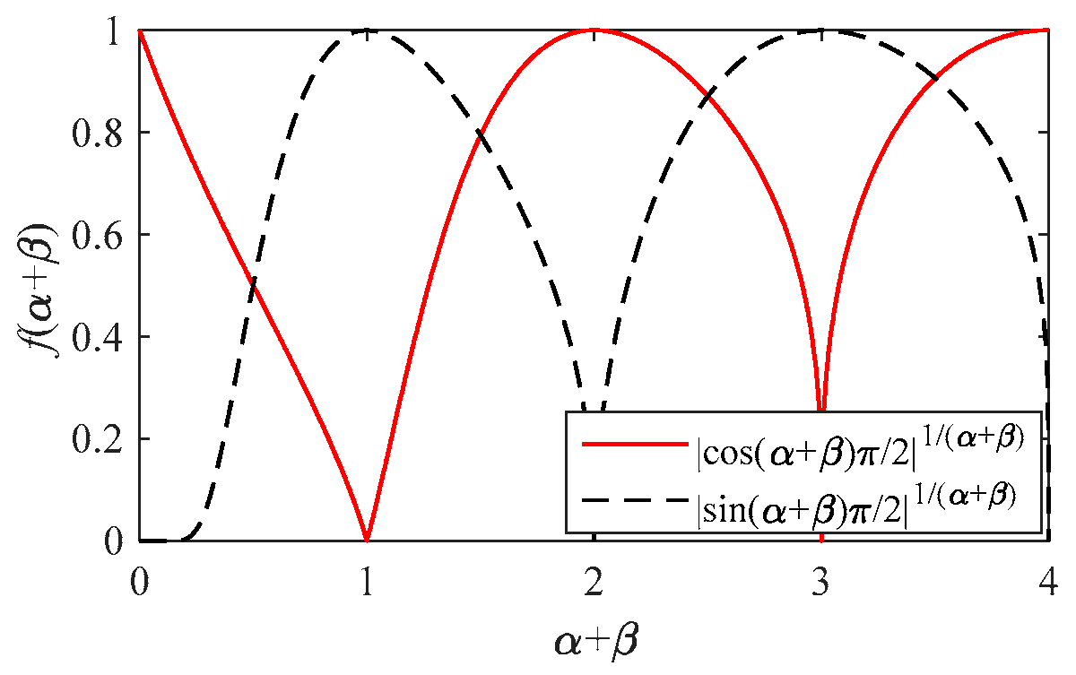
Figure 4.
The change diagram of the digital solution of obtained by the differential evolution algorithm versus plane.
Figure 4.
The change diagram of the digital solution of obtained by the differential evolution algorithm versus plane.
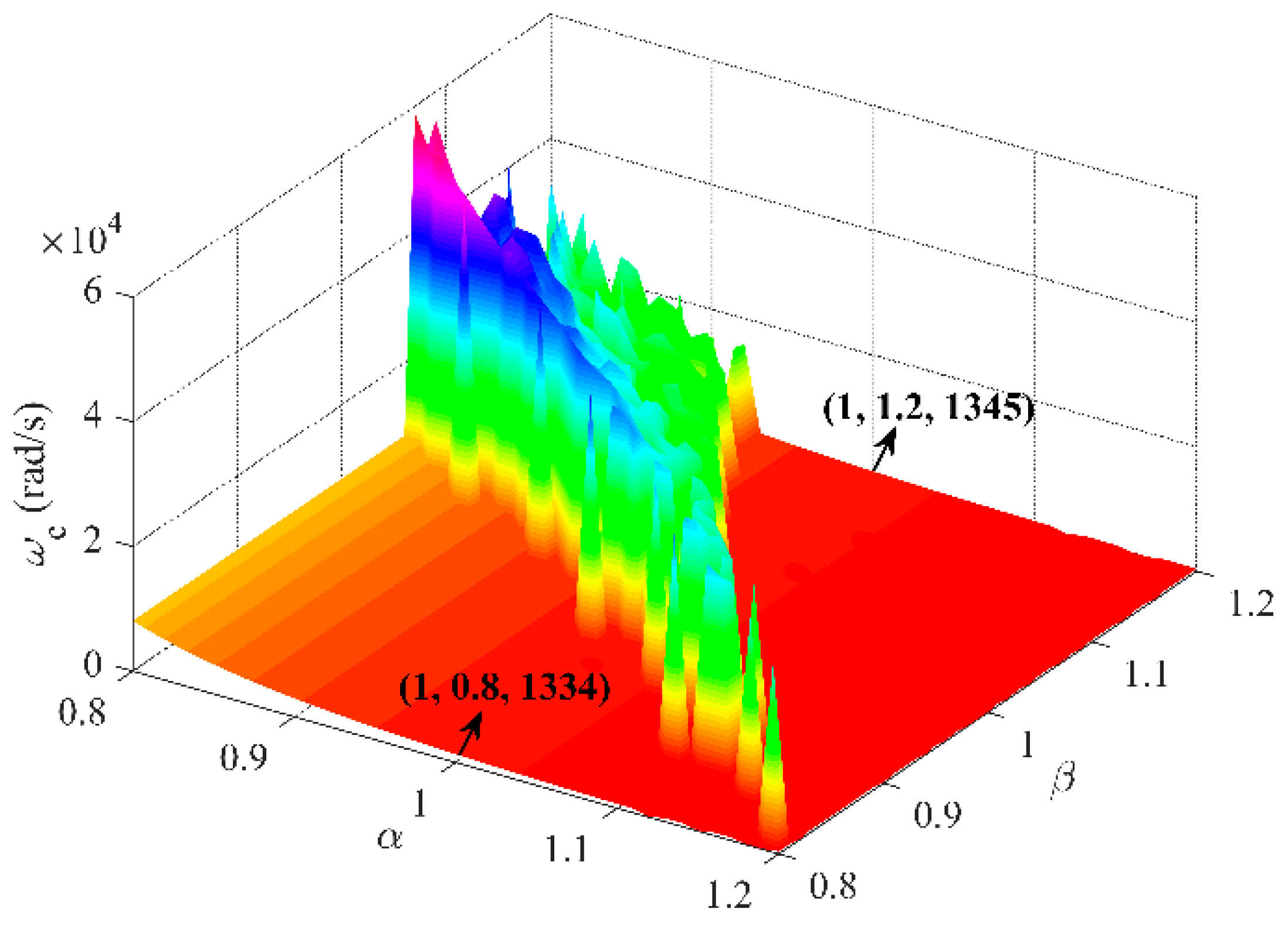
Figure 5.
The frequency characteristic curves of a fractional-order LCL Filter when is constant and changes. (a) The frequency characteristics when . (b) The frequency characteristics when . (c) The frequency characteristics when .
Figure 5.
The frequency characteristic curves of a fractional-order LCL Filter when is constant and changes. (a) The frequency characteristics when . (b) The frequency characteristics when . (c) The frequency characteristics when .

Figure 6.
The frequency characteristic curves of a fractional-order LCL Filter when is constant and changes. (a) The frequency characteristics when . (b) The frequency characteristics when . (c) The frequency characteristics when .
Figure 6.
The frequency characteristic curves of a fractional-order LCL Filter when is constant and changes. (a) The frequency characteristics when . (b) The frequency characteristics when . (c) The frequency characteristics when .


Table 1.
The frequency characteristic indicators of a fractional-order LCL when is constant and changes.
Table 1.
The frequency characteristic indicators of a fractional-order LCL when is constant and changes.
| Serial Number | (rad/s) | (dB) | (rad/s) | (°) | (rad/s) | ||
|---|---|---|---|---|---|---|---|
| 1 | 0.8 | 0.6 | 5,257,083 | 53.39 | 8059 | 107.98 | 2,024,102 |
| 2 | 0.8 | 0.8 | 508,310 | 28.80 | 8075 | 107.93 | 329,599 |
| 3 | 0.8 | 1.0 | 98,864 | 9.06 | 8186 | 107.76 | 87,883 |
| 4 | 0.8 | 1.2 | 28,867 | −79.03 | 33,194 | −72.00 | 28,867 |
| 5 | 0.8 | 1.4 | NaN | Inf | 13,749 | 241.70 | 11,092 |
| 6 | 1.0 | 0.6 | 429,574 | 47.38 | 1334 | 90.00 | 329,598 |
| 7 | 1.0 | 0.8 | 92,922 | 27.10 | 1334 | 89.99 | 87,883 |
| 8 | 1.0 | 1.0 | 28,867 | −75.58 | 29,510 | 90.00 | 28,867 |
| 9 | 1.0 | 1.2 | NaN | Inf | 1345 | 90.16 | 11,092 |
| 10 | 1.0 | 1.4 | NaN | Inf | 1379 | 91.43 | 4772 |
| 11 | 1.2 | 0.6 | 87,883 | 45.96 | 402 | 71.99 | 87,882 |
| 12 | 1.2 | 0.8 | 28,867 | −57.73 | 28,950 | −108.0 | 28,867 |
| 13 | 1.2 | 1.0 | NaN | Inf | 402 | 72.01 | 11,092 |
| 14 | 1.2 | 1.2 | NaN | Inf | 402 | 72.07 | 4772 |
| 15 | 1.2 | 1.4 | NaN | Inf | 403 | 72.33 | 2487 |
Table 2.
The frequency characteristic indicators of a fractional-order LCL when is constant and changes.
Table 2.
The frequency characteristic indicators of a fractional-order LCL when is constant and changes.
| Serial Number | (rad/s) | (dB) | (rad/s) | (°) | (rad/s) | ||
|---|---|---|---|---|---|---|---|
| 1 | 0.6 | 0.8 | 19,437,846 | 50.51 | 16,538 | 124.85 | 2,024,630 |
| 2 | 0.8 | 0.8 | 508,310 | 28.80 | 8075 | 107.93 | 329,599 |
| 3 | 1.0 | 0.8 | 92,922 | 27.10 | 1334 | 89.99 | 87,883 |
| 4 | 1.2 | 0.8 | 28,867 | −57.73 | 28,950 | −108.0 | 28,867 |
| 5 | 1.4 | 0.8 | NaN | Inf | 171 | 54.00 | 11,092 |
| 6 | 0.6 | 1.0 | 686,670 | 13.13 | 368,962 | 56.77 | 329,598 |
| 7 | 0.8 | 1.0 | 98,864 | 9.06 | 8186 | 107.76 | 87,882 |
| 8 | 1.0 | 1.0 | 28,867 | −75.58 | 29,510 | −90.00 | 28,867 |
| 9 | 1.2 | 1.0 | NaN | Inf | 402 | 72.01 | 11,092 |
| 10 | 1.4 | 1.0 | NaN | Inf | 171 | 54.01 | 4772 |
| 11 | 0.6 | 1.2 | 107,916 | −7.69 | 133,810 | −19.98 | 87,883 |
| 12 | 0.8 | 1.2 | 28,867 | −93.42 | 33,192 | −72.00 | 28,867 |
| 13 | 1.0 | 1.2 | NaN | Inf | 1345 | 90.16 | 11,092 |
| 14 | 1.2 | 1.2 | NaN | Inf | 402 | 72.07 | 4771 |
| 15 | 1.4 | 1.2 | NaN | Inf | 170.7 | 54.04 | 2487 |
Table 3.
The comparison between an integer-order LCL filter and a fractional-order LCL filter.
| Properties | Integer-Order LCL Filters | Fractional-Order LCL Filters | Notes on Fractional-Order LCL Filters |
|---|---|---|---|
| Variables | Three Variables | Five Variables | is the order of the fractional-order inductors, and is the order of the fractional-order capacitor. |
| Range of and | An integer-order LCL filter is the special case of a fractional-order LCL filter when . | ||
| The transfer function, | |||
| Resonance peak | Exists a resonance peak | Exists a resonance peak when | The necessary and sufficient condition for the existence of a resonance peak is . |
| Resonant frequency, | is determined by the values of , , and , and is independent of and . | ||
| Corner frequency, | According to the different value range of , there are two calculation formulas of . is affected by both and . | ||
| Slope of the logarithmic magnitude-frequency characteristic, | The slope is only determined by when , while is affected by both and when . The range of slope is (0 dB/dec, −40 dB/dec) and (0 dB/dec, −120 dB/dec) when and , respectively. | ||
| Center frequency, | is affected by both and . | ||
| Phase-frequency characteristic, | is only determined by when , while is affected by both and when . The high-frequency phase curve changes from to the more lagging direction when , and to the opposite direction when . | ||
| Phase crossover frequency, | If and only if , the phase-frequency characteristics of a fractional-order LCL filter has a . |
Disclaimer/Publisher’s Note: The statements, opinions and data contained in all publications are solely those of the individual author(s) and contributor(s) and not of MDPI and/or the editor(s). MDPI and/or the editor(s) disclaim responsibility for any injury to people or property resulting from any ideas, methods, instructions or products referred to in the content. |
© 2024 by the authors. Licensee MDPI, Basel, Switzerland. This article is an open access article distributed under the terms and conditions of the Creative Commons Attribution (CC BY) license (https://creativecommons.org/licenses/by/4.0/).
Share and Cite
MDPI and ACS Style
Xu, J.; Zeng, E.; Li, X.; He, G.; Liu, W.; Meng, X. Fractional-Order LCL Filters: Principle, Frequency Characteristics, and Their Analysis. Fractal Fract. 2024, 8, 38. https://doi.org/10.3390/fractalfract8010038
AMA Style
Xu J, Zeng E, Li X, He G, Liu W, Meng X. Fractional-Order LCL Filters: Principle, Frequency Characteristics, and Their Analysis. Fractal and Fractional. 2024; 8(1):38. https://doi.org/10.3390/fractalfract8010038
Chicago/Turabian StyleXu, Junhua, Ermeng Zeng, Xiaocong Li, Guopeng He, Weixun Liu, and Xuanren Meng. 2024. "Fractional-Order LCL Filters: Principle, Frequency Characteristics, and Their Analysis" Fractal and Fractional 8, no. 1: 38. https://doi.org/10.3390/fractalfract8010038