Two-Directional Operation of Bistable Latchable Micro Switch Actuated by a Single Electrode †


1
School of Mechanical Engineering, Faculty of Engineering, Tel Aviv University, Ramat Aviv 69978, Israel
2
Department of Civil Engineering, Faculty of Engineering, Ariel University, Ariel 44837, Israel
3
Center for Nanoscale Science and Technology, National Institute of Standards and Technology, Gaithersburg, MD 20899, USA
*
Author to whom correspondence should be addressed.
†
Presented at the Eurosensors 2017 Conference, Paris, France, 3–6 September 2017.
Proceedings 2017, 1(4), 277; https://doi.org/10.3390/proceedings1040277
Published: 16 August 2017
(This article belongs to the Proceedings of Proceedings of Eurosensors 2017, Paris, France, 3–6 September 2017)
Abstract
:Curved micromechanical beams are a versatile platform for exploring multistable behavior, with potential applications in mechanical based logic elements and electrical and optical switches. Here we demonstrate bidirectional electrostatic actuation of a bistable, latched, micromechanical beam by the same electrode, which was used for the snap-through switching of the device. The release of the mechanically-latched beam is achieved by pre-loading the structure using a rising voltage applied to the electrode, followed by a sudden decrease of the voltage. This abrupt removal of the loading results in a transient response and dynamic snap-back of the beam.
1. Introduction
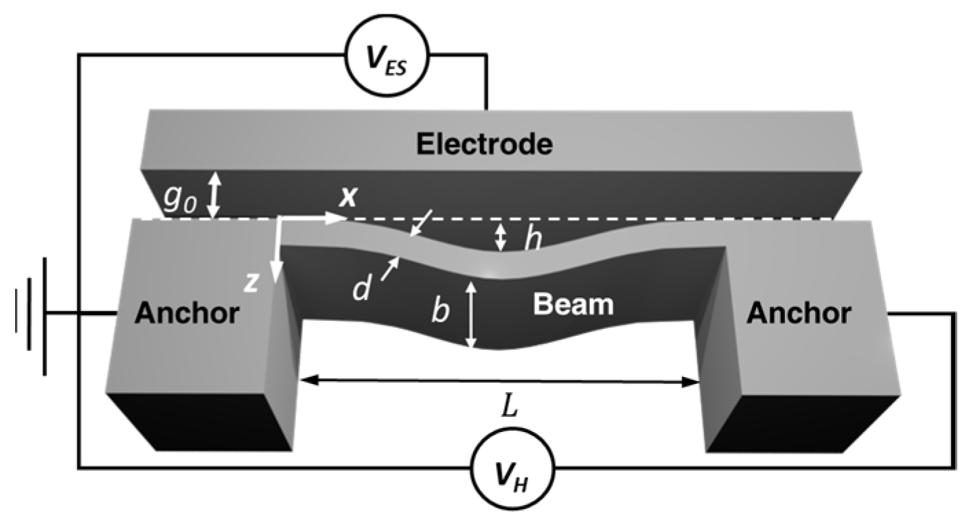
Curved beams (Figure 1) may exhibit two different stable configurations under identical loading conditions. The transition from one stable region to another is referred to as a snap-through. Electrostatically-actuated bistable micro/nanoelectromechanical systems (NEMS/MEMS) are useful for applications such as electrical and optical switches [1], mechanical non-volatile memories [2], locking mechanisms [3], and threshold inertial sensors [4]. The functionality of these devices relies on the ability of an actuating transducer to apply loading in two opposite directions. In the case of electrostatic actuation, electrodes located at two opposite sides of the beam are required to achieve the effect [2,5]. However, such devices are bulky and their design and operation are challenging.
Curved beams that exhibit latching can remain within the nonvolatile, second stable state without any loading. The magnitude of the critical quasi-static release force is a function of the beam geometry and can be negative [5]. In our work, we experimentally show that snap-back can be carried out dynamically, using a single electrode. This was accomplished by a linearly rising load followed by a sudden drop in the actuating field. The behavior of electrostatically actuated, bistable beams was investigated intensively by our group [5,6,7] and others [1,2,8]. However, the latching release approach introduced here was not discussed previously. Our goal was to determine, theoretically and experimentally, the appropriate conditions for a dynamic release. Overall, our results suggest that this single-electrode approach enables batch fabrication of compact bistable micro- and nano-electromechanical systems.
A model, describing the actuation of a curved beam is formulated with the assumptions that the width of the beam, its initial midpoint elevation as well as deflections are all much smaller than the length. Under these assumptions, the beam behavior is described using the Euler-Bernoulli theory with the shallow arch approximation.
2. Model
Assuming a symmetric response, we employ a single-degree-of-freedom (DOF), reduced order model, obtained using the Galerkin decomposition, to describe the beam dynamics [7]. The equation of motion, using the fundamental buckling mode of a straight beam as the base function [5], is
Here ρ, E, A, Iyy and wm are the beam density, effective (plain strain) modulus of elasticity, cross sectional area, moment of inertia and the beam midpoint elevation above the clamped ends, respectively, Figure 1. ε0 = 8.854 × 10⁻¹² F·m−1 is the permittivity of free space, c is the damping coefficient, VES is the actuation voltage. While a multi degree of freedom model captures symmetry breaking behavior [5,6,7,8], we found that the simpler, single DOF model is adequate for describing leading static and dynamic effects. Figure 2a shows a static equilibrium curve of the beam. A negative release voltage (meaning that the electrostatic force is applied in an opposite direction), and latching points at zero voltage are observed [5]. It was shown theoretically in [5], that the beam can be dynamically switched from the latching state back to its initial position with a sudden voltage drop. The beam in the latched state is subjected to a quasi-static loading of duration T given by
where Vmax is the peak voltage value, and H is the Heaviside step function. The equation specifies a slowly increasing voltage, defined by T, to a value of Vmax. During this process, the beam gains strain energy while moving towards the electrode. At Vmax, the signal abruptly drops to zero, causing the release of the accumulated energy. The beam crosses the latching point at a sufficiently high velocity, and switches back to its initial state. Figure 2b shows results from two time-dependent loading scenarios. Our data show that Vmax = 10 V was insufficient for the transition to occur, whereas Vmax = 50 V shows dynamic switching.
3. Experiment
3.1. Experimental Procedure & Equipment
To explore the phenomenon, we used beams fabricated from highly-doped single-crystal Si using silicon on insulator (SOI) substrates. Details of the fabrication procedure are outlined in [7]. Each die comprised 40 identical beams characterized by nominal values of b = 20 µm, d = 3.5 µm, g0 = 10 µm, L = 1000 µm and various h’s. Dimensions of the fabricated micromechanical beams were measured using optical microscopy, yielding d = (3.31 ± 0.09) µm, g0 = (10.97 ± 0.09) µm and h = (2.12 ± 0.09) µm. The reported values are (mean ± one standard deviation), with uncertainties determined from the pixel to µm ratio from the camera resolution [5,8].
Using a wafer probe station, device dynamics were interrogated under room temperature and ambient conditions. The dynamic electrical signal was generated with a signal processor and amplified ×20 using a dual-channel amplifier. Visualization of the in-plane (parallel to the wafer surface) motion of the beam, captured at a frame rate of 5 Hz, was achieved using a camera mounted on a trinocular optical microscope.
3.2. Experimental Results
We used quasi-static conditions to characterize the beam static behavior. By slowly increasing VES, we constructed a buckling curve showing the relationship between VES and the midpoint location (wm). Details of the procedure are shown in [7]. In order to induce bistability with a latching point, we increased the beam curvature using Joule heating, by applying a voltage VH across the beam (Figure 1). VH was gradually increased in increments of ≈0.1 V. At each step, the electrostatic loading experiment was carried out until the beam exhibited bistability with latching. VH ≈ 3.3 V, corresponding to h = (4.15 ± 0.09) µm, satisfied both bistability and latching conditions, as shown in Figure 3.
Using our model in Equation (1), with the signal from Equation (2), we released the beam from the latching point by first ramping the voltage gradually to a value of VES ≈ Vmax, and then suddenly dropping VES to zero. Initially, the beam was subjected to a preloading of Vmax ≈ 25 V, however, this value was not sufficient to release the beam. An increase to Vmax ≈ 27.5 V resulted in a dynamic release, returning the beam to its respective initial position, as seen in Figure 4.
4. Summary & Conclusions
We demonstrated a curved, bistable, latched beam transition from the second to the initial equilibrium using a single actuating electrode. We experimentally observed transitions from the latching point to the initial state. When the beam is in the latched state, we employed a slowly increasing actuating voltage followed by a sudden drop. During actuation, the beam strain energy continuously grew as it deflected towards the electrode. Upon an abrupt drop in actuation, the release of the accumulated energy allowed the beam a transition to the initial state. Overall, our experimental results confirm the theoretical predictions concerning the possibility of releasing a latched beam using a single electrode actuation.
Acknowledgments
The devices were fabricated and tested at the Center for Nanoscale Science and Technology Facility (CNST) at the National Institute of Standards and Technology and at the Tel Aviv University MEMS design and characterization lab (MDCL). The authors would like to thank Stella Lulinski and Yoav Kessler for their help with the experiments. This research is supported by Ariel University, Israel Ministry of Science, Technology & Space, and Israel Science Foundation (ISF, grant no. 1272/16).
Conflicts of Interest
The authors declare no conflict of interest.
References
- Que, L.; Udeshi, K.; Park, J.; Gianchandani, Y.B. A bi-stable electro-thermal RF switch for high power applications. In Proceedings of the 17th IEEE International Conference on Micro Electro Mechanical Systems, Maastricht MEMS 2004 Technical Digest, Maastricht, The Netherlands, 25–29 January 2004; pp. 797–800. [Google Scholar]
- Charlot, B.; Sun, W.; Yamashita, K.; Fujita, H.; Toshiyoshi, H. Bistable nanowire for micromechanical memory. J. Micromech. Microeng. 2008, 18, 045005. [Google Scholar] [CrossRef]
- Qiu, J.; Lang, J.H.; Slocum, A.H.; Weber, A.C. A bulk-micromachined bistable relay with U-shaped thermal actuators. MEMS J. 2005, 14, 1099–1109. [Google Scholar]
- Zhao, J.; Jia, J.; Wang, H.; Li, W. A novel threshold accelerometer with postbuckling structures for airbag restraint systems. IEEE Sens. J. 2007, 7, 1102. [Google Scholar] [CrossRef]
- Medina, L.; Gilat, R.; Krylov, S. Latching in bistable electrostatically actuated curved micro beams. Int. J. Eng. Sci. 2017, 110, 15–34. [Google Scholar] [CrossRef]
- Medina, L.; Gilat, R.; Ilic, B.R.; Krylov, S. Experimental dynamic trapping of electrostatically actuated bistable micro-beams. Appl. Phys. Lett. 2016, 108, 073503. [Google Scholar] [CrossRef] [PubMed]
- Krylov, S.; Ilic, B.R.; Schreiber, D.; Seretensky, S.; Craighead, H. The pull-in behavior of electrostatically actuated bistable microstructures. J. Micromech. Microeng. 2008, 18, 055026. [Google Scholar] [CrossRef]
- Zhang, W.M.; Yan, H.; Peng, Z.K.; Meng, G. Electrostatic pull-in instability in MEMS/NEMS: A review. Sens. Actuators A Phys. 2014, 214, 187–218. [Google Scholar] [CrossRef]
Figure 1.
Schematics of an initially curved beam with length L, elevation h, thickness d, width b, electrode gap distance g0, and actuation voltage VES. Application of VH between the two anchors allows for Joule heating of the micromechanical beam and tailoring of its midpoint elevation.
Figure 1.
Schematics of an initially curved beam with length L, elevation h, thickness d, width b, electrode gap distance g0, and actuation voltage VES. Application of VH between the two anchors allows for Joule heating of the micromechanical beam and tailoring of its midpoint elevation.

Figure 2.
Model results for a bistable beam with L = 1000 µm, b = 20 µm, d = 1 µm, h = 3 µm and g0 = 10 µm: (a) Buckling curve, where I, S, R, L and PI represent the initial position, snap-thorough, release, latching and pull-in points. Dashed gray line represents VES = 0. Arrows represent the motion of the beam midpoint along the equilibrium curve. Dotted arrows signify dynamic transition at point S and towards the electrode at point PI. (b) The simulated response, assuming a quality factor Q = 10, for two different signals: (1) for Vmax = 10 V and (2) Vmax = 50 V. Dashed gray line represents wm = 0.
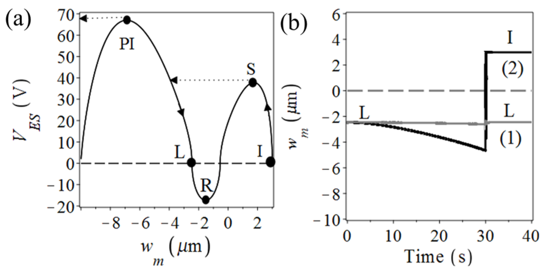
Figure 3.
Experimental results: Joule heating with VH ≈ 3.3 V, induces an elevation of h = (4.15 ± 0.09) µm: (a) Time history showing the snap-through and unloading until the beam is “stuck” at the latching point. (b) Static buckling curve of the heated beam.
Figure 3.
Experimental results: Joule heating with VH ≈ 3.3 V, induces an elevation of h = (4.15 ± 0.09) µm: (a) Time history showing the snap-through and unloading until the beam is “stuck” at the latching point. (b) Static buckling curve of the heated beam.
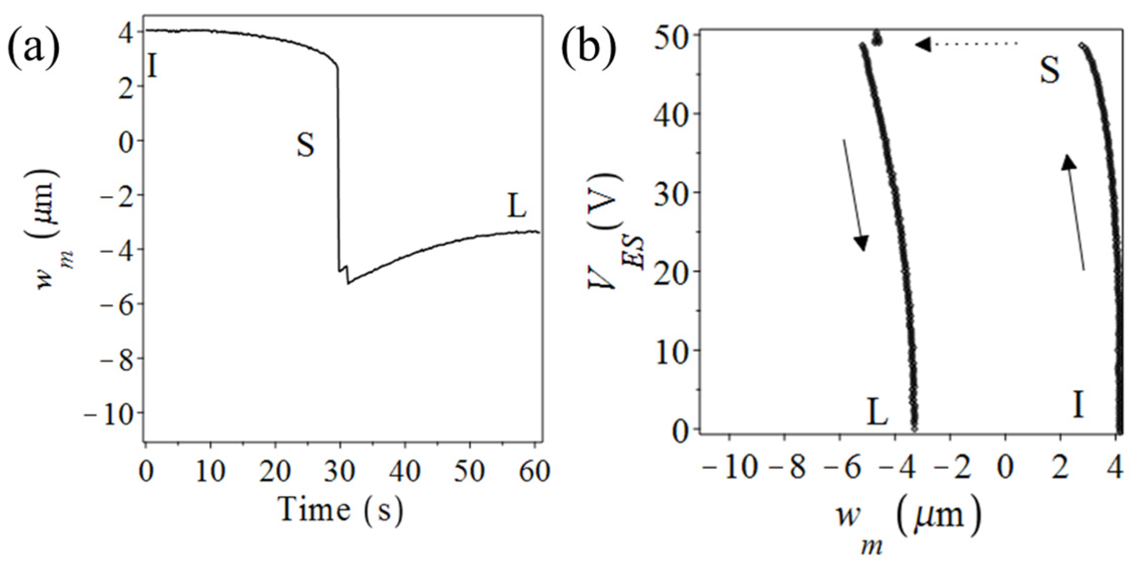
Figure 4.
Experimental results: (a) Time history of a latched beam from Figure 3, actuated by a ramp signal up to Vmax ≈ 27.5 V. Snapshots of the beam: (b) The latched beam at zero voltage. (c) The beam final position at the initial location resulting from a successful dynamic release. Scale bars in (b) and (c) represent (5 ± 0.09) µm (mean ± one standard deviation).

© 2017 by the authors. Licensee MDPI, Basel, Switzerland. This article is an open access article distributed under the terms and conditions of the Creative Commons Attribution (CC BY) license (https://creativecommons.org/licenses/by/4.0/).
Share and Cite
MDPI and ACS Style
Medina, L.; Gilat, R.; Ilic, B.; Krylov, S. Two-Directional Operation of Bistable Latchable Micro Switch Actuated by a Single Electrode. Proceedings 2017, 1, 277. https://doi.org/10.3390/proceedings1040277
AMA Style
Medina L, Gilat R, Ilic B, Krylov S. Two-Directional Operation of Bistable Latchable Micro Switch Actuated by a Single Electrode. Proceedings. 2017; 1(4):277. https://doi.org/10.3390/proceedings1040277
Chicago/Turabian StyleMedina, Lior, Rivka Gilat, Bojan Ilic, and Slava Krylov. 2017. "Two-Directional Operation of Bistable Latchable Micro Switch Actuated by a Single Electrode" Proceedings 1, no. 4: 277. https://doi.org/10.3390/proceedings1040277