Modelling New Techniques for Improving Separation in Miniature Capillary- and Planar-Based Capillary Electrophoresis Systems †


Electronics and Computer Science, University of Southampton, Southampton, UK
*
Author to whom correspondence should be addressed.
†
Presented at the Eurosensors 2017 Conference, Paris, France, 3–6 September 2017.
Proceedings 2017, 1(4), 278; https://doi.org/10.3390/proceedings1040278
Published: 16 August 2017
(This article belongs to the Proceedings of Proceedings of Eurosensors 2017, Paris, France, 3–6 September 2017)
Abstract
:The capillary/channel length is an important factor in capillary electrophoresis (CE) systems since it is directly related to the amount of separation attainable. In this work we present methods to increase the effective channel length without the need to modify the physical channel length. Using an electrode located close to the capillary surface it is possible to dynamically modify zeta-potential and therefore the electroosmotic flow (EOF). By controlling the EOF, certain ionic species within a sample can be held in a short channel whilst other species migrate along the channel. Alternatively the sample can be transported back and forth along the active channel length until sufficient separation has been attained. CE enables detailed analysis of a sample’s composition and this is of interest to a range of applications.
1. Introduction
The aim of this work is to improve the applicability of capillary electrophoresis (CE) in both portable and in-situ devices. In conventional CE a sample migrates along a capillary or micro-machined channel when subjected to an electric-field. As the sample migrates, it begins to separate into its constituent components due to differences in their electrophoretic mobilities. Hence the channel length is a key factor in the amount of separation that can be achieved, although simply increasing its length to maximise separation limits the ability to miniaturise CE systems. To address this issue, novel separation enhancement methods need to be developed and for example approaches involving complex buffering solutions or channel wall coatings have been tried. These are specific both to the application and the species to be separated [1]. In this work, the dynamic control of the electroosmotic flow (EOF) is investigated using computational modelling. Controlling this flow allows the effective channel length to be increased by affecting the residency time of the sample in the channel under given separation conditions, allowing greater separations between species for a given length of channel. It should be noted that the techniques described can be applied to a wide range of applications typical to CE. This includes, for example, the analysis of amino acids and proteins, organic acids, DNA and enzymes. Other applications of standard CE include aiding the separation and detection of substances found in explosive media and nerve agent degradation products, such as those used by terrorists. Other biological and chemical species such as uric acid, ascorbic acid, carbohydrates and glucose etc. have also attracted attention. These examples demonstrate the attractiveness of CE as a powerful separation technique and unsurprisingly this has prompted numerous attempts at miniaturisation [1].
To investigate the separation enhancement methods proposed, a computational model has been developed using COMSOL Multiphysics 4.2a. With fabrication in mind, the cases of both a capillary-based and planar-based device are considered, resulting in a computational model which serves as a design tool for miniaturised CE systems. Examples for the case of a mixed sample of Cu2+, Fe2+ and Fe3+ ions are used to demonstrate the use of the model for a corrosion monitoring application. These metal ions have similar electrophoretic mobilities which make their separation difficult, but the use of the models described in this paper improves the separation without compromising the channel length and consequently the device size.
Controlling the EOF (and Zeta-Potential)
An electric-field applied along the length of a fluid filled channel will cause a mixed sample of ions to migrate along the channel. The charged species within the sample migrate at different velocities dependent on their electrophoretic mobility combined with a fixed velocity contribution from the EOF. If the sample consists of a mixture of cations, they will all be attracted to the cathode. If the EOF also flows towards the cathode then attaining a good separation within a short channel length becomes problematic. This is because the sample will migrate along the channel in a short time as both the EOF and electrophoretic flow act in the same direction, but only the electrophoretic force acts to separate the sample. In general, the longer the sample is present in the electric-field the larger the separation that will occur. Some researchers try to eliminate EOF by modifying the channel walls prior to performing the separation [2]. Commonly, researchers report work where they modify buffer solutions to get the EOF to a fixed value that is favourable for their required separation. In the work reported here however, the EOF needs to be modified dynamically. This can be achieved by placing an electrode, referred to as the zeta-potential modification (ZPM) electrode, close to the capillary or channel surface [3]. The application of a potential on this electrode modifies the charge on the inside surface of the channel wall which in turn alters the zeta-potential and therefore the EOF [4]. There have been numerous reports of experimental results regarding the modification of the EOF using external electric fields on both chip- and non-chip-based CE systems [1]. The majority of the reported work has been on characterising the ability to modify the EOF, rather than investigating the benefits of EOF control for the improvement of separation. Culbertson et al. and Kašička et al. show how the resolution of CE systems can be improved by the control of EOF for capillary based systems [5]. The extension of this to planar systems has received less attention. Further to this, there has been little if any computation modelling of the dynamic modification of the EOF. This is important for describing the enhancement in the resolution and for use as a design tool for systems incorporating the separation enhancement methods.
2. Separation Enhancement Routines
As an illustration, we investigate a mixed sample of Cu2+, Fe2+ and Fe3+ ions in a channel with width, height and length of 300 μm, 50 μm and 80 mm respectively using COMSOL 4.2a, where the ZPM electrode can be dynamically controlled. Two separation enhancement routines are described here. The first matches the EOF to oppose the velocity of the ions being separated, whereas the second modifies the EOF numerous times throughout an experimental run causing the sample to migrate back and forth along the channel multiple times.
2.1. Method 1: Matching EOF to Electrophoretic Flow
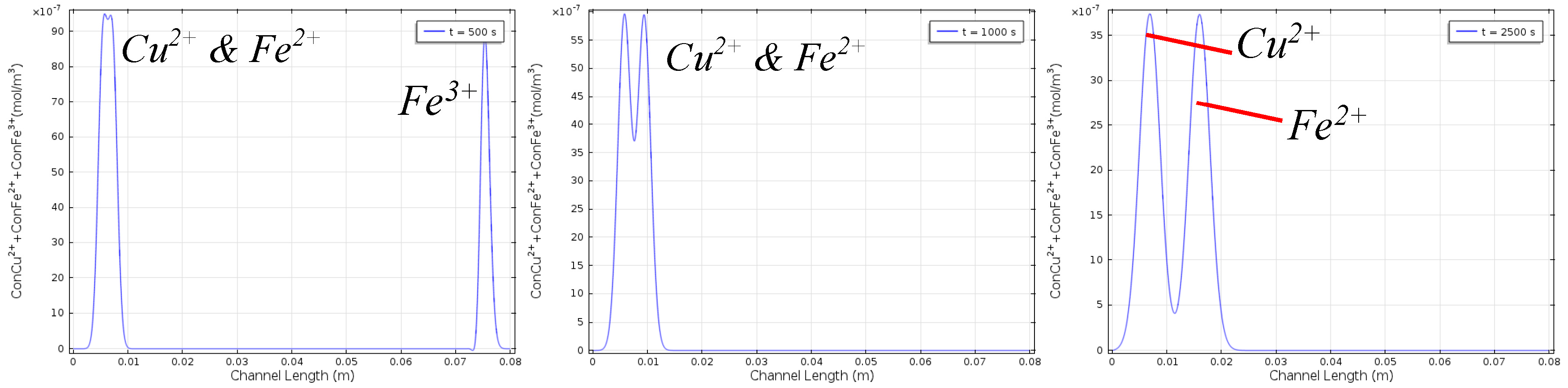
Consider the case of a sample of two ionic species, species SA and SB where SA has the higher electrophoretic mobility. After some time travelling along a channel subjected to an electric-field, SA will move ahead of SB and the sample will become separated. This assumes that the channel is long enough for the differences in the values of electrophoretic mobility to produce sufficient separation for the two ionic species to be considered as effectively isolated from each other. If the two ions have similar electrophoretic mobilities then a long channel length would be required to separate them. A solution to this is to reduce the absolute velocities of the two species whilst maintaining their difference in velocity. This can be achieved by making the EOF oppose the direction of flow of charged species along the channel (Figure 1).
The concept of matching the EOF to the electrophoretic flow relies on understanding how the potential applied to the ZPM electrode affects the EOF. The values of electrophoretic mobility of the analytes being separated must also be known. In the case of the mixed sample of species SA and SB, if a potential is applied to the ZPM electrode to make the EOF equal and opposite to the velocity of species SB, then the net velocity of SB will be zero and so it will not migrate down the channel. On the other hand, SA, which has the slightly higher mobility, will be able to travel along the channel, albeit relatively slowly. It is possible to calculate the time taken for species SA to separate from SB; further to this it is also possible to work out the minimum channel length required to allow complete separation. For samples where there are more than two ionic species to be separated the problem becomes more complicated. However, in many cases matching the EOF to be equal in magnitude and opposite in direction to the mean velocity of the ensemble of ionic species will significantly improve the separation. The composition of every sample is different and so the optimum value for EOF will vary. It is impractical to perfectly match the EOF to the species velocity either by modification of the buffer solution (since every sample would require a different buffer solution composition) or indeed by using a ZPM electrode without using some form of active control, although we suggest a possible method for providing this. An alternative method (method 2) is introduced to mitigate this requirement for highly precise control of the EOF and thus may be considered a more practical method.
2.2. Method 2: Switching EOF Direction to Cycle Ion Movement in the Channel
By using a ZPM electrode it is possible to completely reverse the direction of EOF. Hence a sample can be made to migrate from the injection point to the end of the channel (taking care to prevent the sample from leaving the channel) and then by reversing the EOF, the sample can be made to migrate back toward the start of the channel. Upon approaching the start of the channel, the EOF can be reset back to its original value enabling the sample to migrate toward the end of the channel once again. This cycle can be repeated a number of times, significantly increasing the total distance travelled by the sample when compared to the fixed length of the channel.
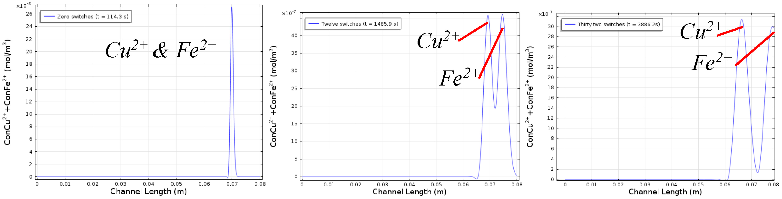
Figure 2 shows a sequence of illustrations to demonstrate the switching EOF separation enhancement method. The results from the COMSOL simulation can be seen in Figure 3. It can be seen that when the sample reaches the end of the channel for the first time, there is some separation but not enough to clearly distinguish the analytes. By reversing the EOF the sample is moved back to the start of the channel, without affecting the separation already achieved. The original EOF direction is re-established and the sample then migrates along the channel once again, and when it reaches the end of the channel for a second time, it has become further separated. Upon each successive migration along the channel length the sample becomes further separated. This process can be repeated until the ions are sufficiently separated such that different groups of ions can be detected individually. The migration time of the ions in the electric-field is greatly increased without compromising the physical channel length. The separated species could still be identified based on their migration time which would enable the use of non-qualitative detection systems, for example contactless conductivity detection.
3. Conclusions
Novel separation enhancement methods based on dynamic control of the EOF have been developed and modelled. These methods enable an increase in the effective channel length without increasing the actual channel length and do not require complex chemical buffering systems. This could be an alternative to complex chemical buffering systems, allowing more generic separation solutions to be implemented rather than highly application specific solutions.
Conflicts of Interest
The authors declare no conflict of interest.
References
- Lewis, A.P.; Cranny, A.; Harris, N.R.; Green, N.G.; Wharton, J.A.; Wood, R.J.K.; Stokes, K.R. Review on the development of truly portable and in-situ capillary electrophoresis systems. Meas. Sci. Technol. 2013, 24, 042001. [Google Scholar] [CrossRef]
- Doherty, E.A.S.; Meagher, R.J.; Albarghouthi, M.N.; Barron, A.E. Microchannel wall coatings for protein separations by capillary and chip electrophoresis. Electrophoresis 2003, 24, 34–54. [Google Scholar] [CrossRef] [PubMed]
- Van der Wouden, E.J.; Heuser, T.; Hermes, D.C.; Oosterbroek, R.E.; Gardeniers, J.G.E.; van den Berg, A. Field-effect control of electro-osmotic flow in microfluidic networks. Colloids Surfaces A Physicochem. Eng. Asp. 2005, 267, 110–116. [Google Scholar] [CrossRef]
- Van der Wouden, E.J.; Hermes, D.C.; Gardeniers, J.G.; van den Berg, A. Directional flow induced by synchronized longitudinal and zeta-potential controlling AC-electrical fields. Lab Chip 2006, 6, 1300–1305. [Google Scholar] [CrossRef] [PubMed]
- Kašička, V.; Prusík, Z.; Sázelová, P.; Brynda, E.; Stejskal, J. Capillary zone electrophoresis with electroosmotic flow controlled by external radial electric field. Electrophoresis 1999, 20, 2484–2492. [Google Scholar] [CrossRef]
Figure 1.
Simulation with EOF set to be about equal and opposite to the mobility of Cu2+.

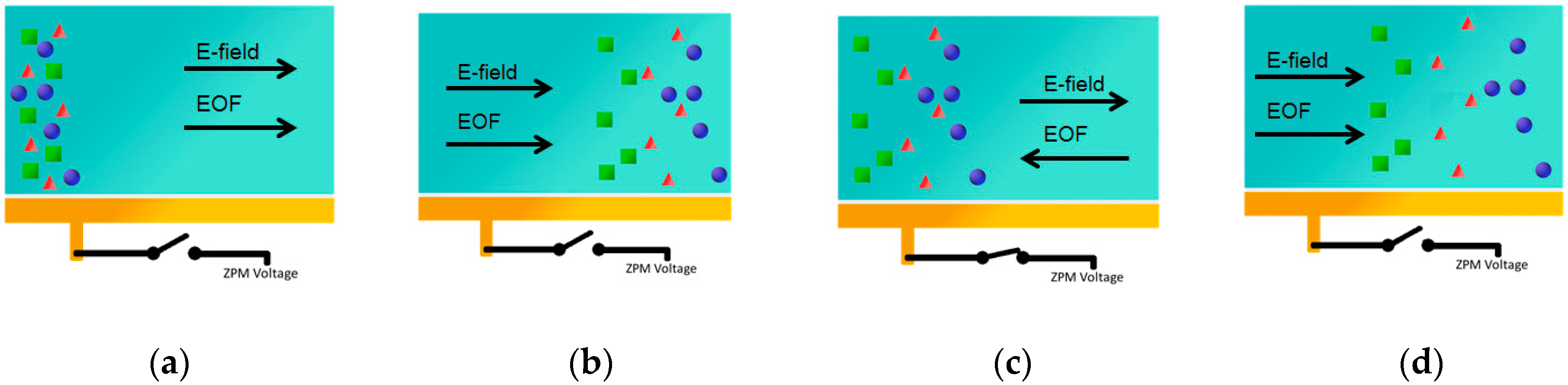
Figure 2.
Illustration of switching EOF separation enhancement method. The blue (●) ions have the highest mobility, followed by the red (▲) ions, with the green (■) ions having the lowest mobility. (a) Sample of mixed ions injected into channel. (b) Sample approaches end of channel. Sample starts to separate but many ions still overlap. (c) Voltage applied to ZPM electrode. EOF reversed sending ions back to start of channel whilst maintaining their separation. (d) Sample approaches end of channel again. Separation of sample is improved.

Figure 3.
Simulation results showing the effect of the EOF switching to send the sample back and forth along the channel. Number of EOF switches: is shown in the legend of each graph. Sample is depicted at the end of the channel in each instance.
Figure 3.
Simulation results showing the effect of the EOF switching to send the sample back and forth along the channel. Number of EOF switches: is shown in the legend of each graph. Sample is depicted at the end of the channel in each instance.

Publisher’s Note: MDPI stays neutral with regard to jurisdictional claims in published maps and institutional affiliations. |
© 2017 by the authors. Licensee MDPI, Basel, Switzerland. This article is an open access article distributed under the terms and conditions of the Creative Commons Attribution (CC BY) license (https://creativecommons.org/licenses/by/4.0/).
Share and Cite
MDPI and ACS Style
Lewis, A.; Harris, N. Modelling New Techniques for Improving Separation in Miniature Capillary- and Planar-Based Capillary Electrophoresis Systems. Proceedings 2017, 1, 278. https://doi.org/10.3390/proceedings1040278
AMA Style
Lewis A, Harris N. Modelling New Techniques for Improving Separation in Miniature Capillary- and Planar-Based Capillary Electrophoresis Systems. Proceedings. 2017; 1(4):278. https://doi.org/10.3390/proceedings1040278
Chicago/Turabian StyleLewis, Adam, and Nick Harris. 2017. "Modelling New Techniques for Improving Separation in Miniature Capillary- and Planar-Based Capillary Electrophoresis Systems" Proceedings 1, no. 4: 278. https://doi.org/10.3390/proceedings1040278