Geometrical Optimisation of Diode-Based Calorimetric Thermal Flow Sensors through Multiphysics Finite Element Modelling †


1
Engineering Department, University of Cambridge, Cambridge CB2 1TN, UK
2
Flusso Ltd., Cambridge CB21 5XE, UK
*
Author to whom correspondence should be addressed.
†
Presented at the Eurosensors 2017 Conference, Paris, France, 3–6 September 2017.
Proceedings 2017, 1(4), 280; https://doi.org/10.3390/proceedings1040280
Published: 11 August 2017
(This article belongs to the Proceedings of Proceedings of Eurosensors 2017, Paris, France, 3–6 September 2017)
Abstract
:For the first time, 3D multiphysics finite element modelling has been used to optimise the geometry of a calorimetric thermal flow sensor. The model involves and couples three physics domains: electric, thermal and fluid mechanics. The model is validated against experimental data obtained from a thermoelectronic flow sensor comprising of a tungsten heating resistor and temperature sensing diodes. Upstream and downstream diodes measure the temperature change caused by the asymmetric thermal profile when gas flow is introduced. The optimum distance between the diodes and the heater is shown along with the advantages of altering heater and membrane geometries, providing the knowledge for application-driven sensor optimisation.
1. Introduction
At a solid-fluid boundary there is a shear stress exerted when the fluid is moving, generated due to the viscosity of the fluid and the no-slip condition. This solid-fluid interaction results in the development of a velocity boundary layer in addition to a thermal boundary layer when coupled with a heat source. Numerically modelling flow sensing is a challenging task due to the complex description of these phenomena and analytical solutions can rarely be attained. Hence, most other simulations presented in literature are significantly simplified and cannot be used to attain quantitative data [1,2]. Our group has previously reported a 3D multiphysics coupled model [3]. In this work, we use the model to optimise the geometry of thermal flow sensors to maximize the sensitivity, ultimately providing the knowledge to tailor sensor geometry to application.
2. Device Structure
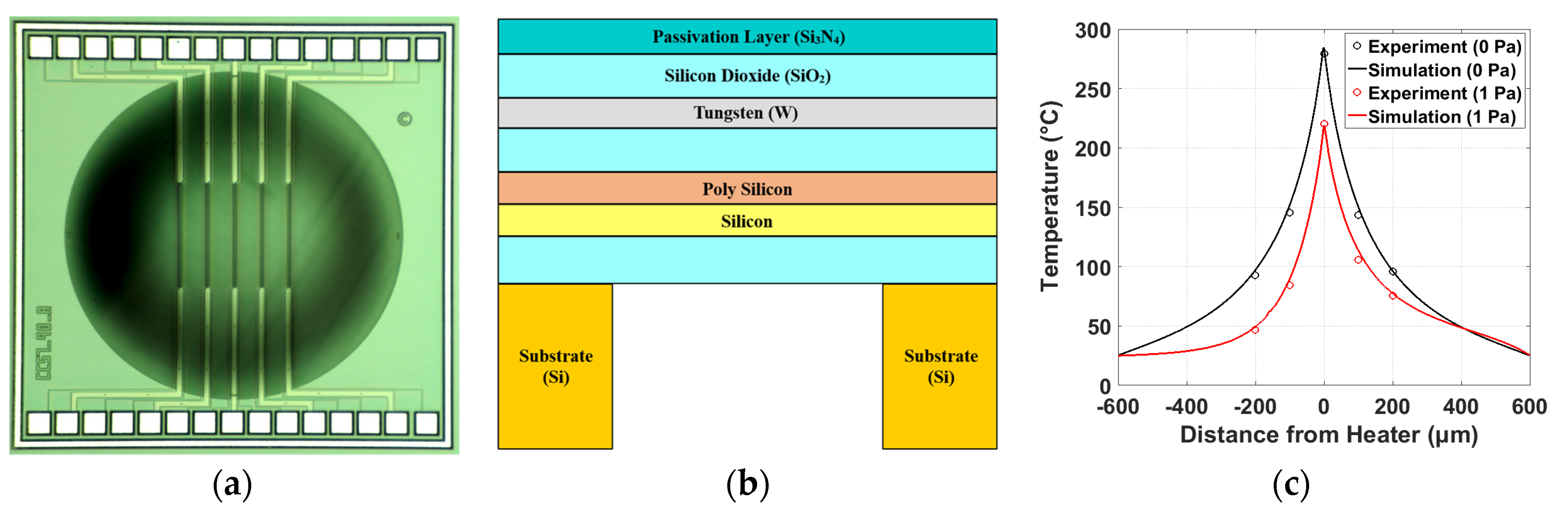
The device presented in this paper is a thermal SOI CMOS MEMS flow sensor (Figure 1a) with the cross-section shown in Figure 1b. Situated in the tungsten layer, there are 5 resistors with dimensions 2 μm × 400 μm × 0.3 μm. The central wire is biased with a constant current (10 mA) and acts as a heat source. Underneath each resistor there are temperature sensing diodes of the same dimensions. These diodes are forward biased at 10 μA and the voltage drop (Vd) between the two junctions is measured and converted into a temperature by: Vd = −0.00157T + 0.76. Thermoelectronic flow sensors have the benefit over conventional thermoresistive sensors that the temperature sensor and heating element are two different components and can therefore be optimised separately. Other advantages and a detailed description of the diode-based flow sensor can be found in [4].
3. Numerical Model
COMSOL Multiphysics was used to define and implement the numerical simulation. The model consisted of three separate yet interlacing physics modules that were: (a) Electric Current—a biasing current is defined for the central resistor and locally heats up the membrane via Joule heating, (b) Heat Transfer—due to the temperature gradient between the heated resistor and the surrounding media, heat transfer into the membrane through conduction is defined as well as through conduction and convection into the fluid above and below the membrane, and (c) Fluid Dynamics—laminar flow is introduced through the fluid above the membrane, affecting the amount of forced convection into the fluid. This results in an asymmetric thermal profile and changes the operating temperature of the heating resistor. Interpolative lookup tables were defined for the material properties due to their dependence on temperature. A detailed overview of the equations and boundary conditions that were defined for this model can be found here [3].
In order to ensure the simulation accurately portrays the device, numerical and experimental results have been compared. The temperature output for varying power (not shown here) matched to within 1% up to the maximum operating temperature of 300 °C, confirming the Joule heating implementation was accurate. The coupling between Joule heating and heat transfer is validated in Figure 1c, where the temperature profile across the chip, parallel to the direction of flow, is shown in stagnant flow condition. Finally, forced convection is also added to the model that matches experimental results within a 5% accuracy.
4. Optimisation
If the heat source is located on a wall where a hydrodynamic boundary layer exists, a thermal boundary layer will also build up. The temperature difference between the upstream and downstream diodes is measured and correlated to the flow conditions; this method is known as the calorimetric approach. In calorimetric thermoelectronic flow sensors the location of the diodes must be optimised for the highest possible sensitivity. A previous work by [5] modelled the temperature profile for various wall shear stresses, but was a very simplified model where the results could not be quantitatively taken and used for geometrical optimisation.
Figure 2a shows that leaving a larger gap between sensing diode and heater results in sharper temperature increase for low wall shear stresses, but the sensitivity saturates earlier. This leads to the conclusion that the optimum distance is dependent on the flow velocities (wall shear stresses) being measured. Figure 2b shows how the temperature difference varies as the diode becomes further from the heater. For each wall shear stress there is an optimum distance where the temperature difference is the largest, hence leading to the highest sensitivity. However this distance becomes larger as the wall shear stress decreases. Therefore we can now select the optimised distance of sensing elements based on the desired range of flows. A constant heater length of 200 µm and heater width of 2 µm were used.
Another important geometrical parameter determining the performance of the sensor is the ratio between the membrane and heater size. Firstly, it is important to minimise the power dissipation into the substrate below. Assuming that the heated area around the hot-film and the membrane are circular and have radii of and respectively, the thermal resistance can be defined as:
where is the thickness of the membrane. If we further assume that the temperature at the edge of the membrane is ambient, i.e., , and that equals the temperature of the sensor, , then the conduction power dissipation through the membrane can be expressed as:
This shows that power loss from the membrane into the substrate depends on membrane thickness and the ratio of . Membrane thickness cannot be altered because it is limited by the foundry fabrication process and must maintain mechanical robustness. Simultaneously to reducing power dissipation into the substrate, it is important to maximise the sensitivity. It is undesirable to increase the diameter of the membrane due to this causing increased fragility and cost. The effect of different ratios can be altered by changing the length of the heater. All simulations were run at a constant power of 11.7 mW and constant membrane diameter of 1.2 mm. The first observation is that shorter heaters have the ability to produce larger temperature differences; due to the fact the current density must increase in order to exhibit identical power. Figure 3a shows the optimum diode distance at each wall shear stress for the different heater lengths. At low wall shear stresses the heater length can be considered negligible. However, when the wall shear stresses are significantly high, using a longer heater provides an optimum diode distance that varies less dramatically, leading to the conclusion that longer heater lengths would be more suitable in situations where a wide range of wall shear stresses need to be measured. The selection of heater length then becomes a compromise and must be chosen for specific application.
Unlike heater length, heater width had negligible effect on the optimum diode distance meaning it should be kept as thin as possible to allow the maximum achievable temperature without exceeding the current density limit. In fact, simulations in stagnant flow (Figure 3b) showed a significant difference in the shape of heated zone within the membrane (more circular for shorter heaters). From this we can deduce that the most important factor in deciding optimum diode distance is the shape of the membrane temperature profile produced by the heater.
The power dissipation presented in Equation (2) assumes that the membrane is circular. It is possible to further optimise the geometry by converting this shape into a square with rounded corners (300 µm radius of curvature) providing the equivalent radius, , of the new shape is used where A is the area of the shape and Pe is the wetted perimeter. When is substituted into Equation (2) there is a reduction in power dissipation by 7% which agrees with the numerical results.
5. Conclusions
A novel diode-based flow sensor, fabricated with SOI CMOS MEMS technology, has been numerically modelled. Simulations were validated against experimental results and proven to be quantitatively accurate. The temperature difference of the upstream and downstream diode was calculated at different distances from the heater for a variety of flow rates, and showed that with increased flow rate the optimum location of the diode becomes closer to the heater. The different optimum distances can be ascribed to a different initial temperature distribution and its evolution with increasing wall shear stress. Furthermore, it was shown that the heater width has negligible effect on the temperature distribution whereas heater length affected the shape of the heated region, resulting in different optimum diode distances. Finally, a rounded square membrane can reduce power dissipation (by 7%). This set of information will ultimately provide the ability for application-driven optimisation of thermal flow sensors by spatial heat generation and temperature distribution sensing engineering.
Acknowledgments
This work was partly supported through the EU FP7 project SOI-HITS (288481).
Conflicts of Interest
The authors declare no conflict of interest.
References
- Lin, Q.; Jiang, F.; Wang, X.-Q.; Han, Z.; Tai, Y.-C.; Lew, J.; Ho, C.-M. MEMS thermal shear-stress sensors: Experiments, theory and modelling. In Proceedings of the Technical Digest of the 2000 Solid-State Sensor and Actuator Workshop, Hilton Head, SC, USA, 4–8 June 2000; pp. 304–307. [Google Scholar]
- Fürjes, P.; Légrádi, G.; Dücső, C.; Aszódi, A.; Bársony, I. Thermal characterisation of a direction dependent flow sensor. Sens. Actuators A Phys. 2004, 115, 417–423. [Google Scholar] [CrossRef]
- Falco, C.; de Luca, A.; Safaz, S.; Haneef, I.; Coull, J.; Ali, S.; Udrea, F. 3-D Multiphysics modelling of a SOI CMOS MEMS thermal wall shear stress sensors. Procedia Eng. 2015, 87, 628–631. [Google Scholar] [CrossRef]
- De Luca, A.; Falco, C.; Gardner, E.L.W.; Coull, J.D.; Udrea, F. Diode-Based CMOS MEMS Thermal Flow Sensors. In Proceedings of the Transducers 2017—19th International Conference on Solid-State Sensors, Actuators and Microsystems, Kaohsiung, Taiwan, 18–22 June 2017. [Google Scholar]
- Sabaté, N.; Santander, J.; Fonseca, L.; Gràcia, I.; Cané, C. Multi-range silicon micromachined flow sensor. Sens. Actuators A Phys. 2004, 110, 282–288. [Google Scholar] [CrossRef]
Figure 1.
(a) Optical micrograph of the fabricated thermoelectronic flow sensor (size: 1.6 mm x 1.6 mm); (b) the cross-section of the sensor (not to scale) and (c) temperature profile parallel to the direction of flow at no flow (wall shear stress 0 Pa) and flow (wall shear stress 1 Pa).
Figure 1.
(a) Optical micrograph of the fabricated thermoelectronic flow sensor (size: 1.6 mm x 1.6 mm); (b) the cross-section of the sensor (not to scale) and (c) temperature profile parallel to the direction of flow at no flow (wall shear stress 0 Pa) and flow (wall shear stress 1 Pa).

Figure 2.
(a) Temperature difference against wall shear stress for the calorimetric method and (b) temperature output as a function of diode distance from central heater for varying wall shear stress.
Figure 2.
(a) Temperature difference against wall shear stress for the calorimetric method and (b) temperature output as a function of diode distance from central heater for varying wall shear stress.

Figure 3.
(a) Optimum diode distance for varying wall shear stress at 4 different heater lengths and (b) showing the difference in heated region shape for heater lengths 200 µm and 800 µm.
Figure 3.
(a) Optimum diode distance for varying wall shear stress at 4 different heater lengths and (b) showing the difference in heated region shape for heater lengths 200 µm and 800 µm.

© 2017 by the authors. Licensee MDPI, Basel, Switzerland. This article is an open access article distributed under the terms and conditions of the Creative Commons Attribution (CC BY) license (https://creativecommons.org/licenses/by/4.0/).
Share and Cite
MDPI and ACS Style
Gardner, E.L.; Luca, A.D.; Falco, C.; Udrea, F. Geometrical Optimisation of Diode-Based Calorimetric Thermal Flow Sensors through Multiphysics Finite Element Modelling. Proceedings 2017, 1, 280. https://doi.org/10.3390/proceedings1040280
AMA Style
Gardner EL, Luca AD, Falco C, Udrea F. Geometrical Optimisation of Diode-Based Calorimetric Thermal Flow Sensors through Multiphysics Finite Element Modelling. Proceedings. 2017; 1(4):280. https://doi.org/10.3390/proceedings1040280
Chicago/Turabian StyleGardner, Ethan L., Andrea De Luca, Claudio Falco, and Florin Udrea. 2017. "Geometrical Optimisation of Diode-Based Calorimetric Thermal Flow Sensors through Multiphysics Finite Element Modelling" Proceedings 1, no. 4: 280. https://doi.org/10.3390/proceedings1040280