Reduction of Electrostatic Control Voltage with a Tri-Electrode Actuator †

Department of Electrical and Computer Engineering, University of Manitoba, Winnipeg, MB R3T 5V6, Canada
*
Author to whom correspondence should be addressed.
†
Presented at the Eurosensors 2017 Conference, Paris, France, 3–6 September 2017.
Proceedings 2017, 1(4), 282; https://doi.org/10.3390/proceedings1040282
Published: 11 August 2017
(This article belongs to the Proceedings of Proceedings of Eurosensors 2017, Paris, France, 3–6 September 2017)
Abstract
:We present a new tri-electrode topology for reducing the control voltage for electrostatic actuators. Conventional parallel plate actuators are dual-electrode systems, formed by the MEMS structure and the drive electrode. By placing a perforated intermediate electrode between these elements, a tri-electrode configuration is formed. This topology enables a low voltage on the intermediate electrode to modulate the electrostatic force on the MEMS device, while the higher voltage on the drive electrode remains fixed. Results presented show that in comparison to conventional parallel plate electrostatic actuators, the intermediate electrode’s modulating voltage can be as low as 20% of normal, while still providing the full actuation stroke.
1. Introduction
Conventional electrostatic actuators suffer pull-in after displacing only approximately 1/3 of the electrode separation [1], thereby limiting the controllable displacement range. Accordingly, the driver electrode must be placed distant from the MEMS structure when large controllable stroke is required. However, this leads to significantly elevated driving voltage, since the electrostatic force is proportional to the square of the separation distance. Various researches have been carried out [2,3,4,5,6,7] to overcome the drawback. Shai Shmulevich et al. [2] proposed a design with a nonlinear spring whose spring constant increases as the actuator closes, and an 18.6 µm out of 21 µm was achieved; Holger Conrad et al. [3] came up with a v-shaped actuator design so that the displacement is amplified by angle between the pulling direction and actuation direction. Other methods also exist such as nonlinear driver electrodes [4] and bi-directional moving of the upper electrode [5,6]. In [7], a capacitor in series with the electrode power supply was explored to avoid pull-in. However, this still suffers from the requirement for larger voltage as the series capacitor is charged in the effort to mitigate positive feedback of MEMS motion.
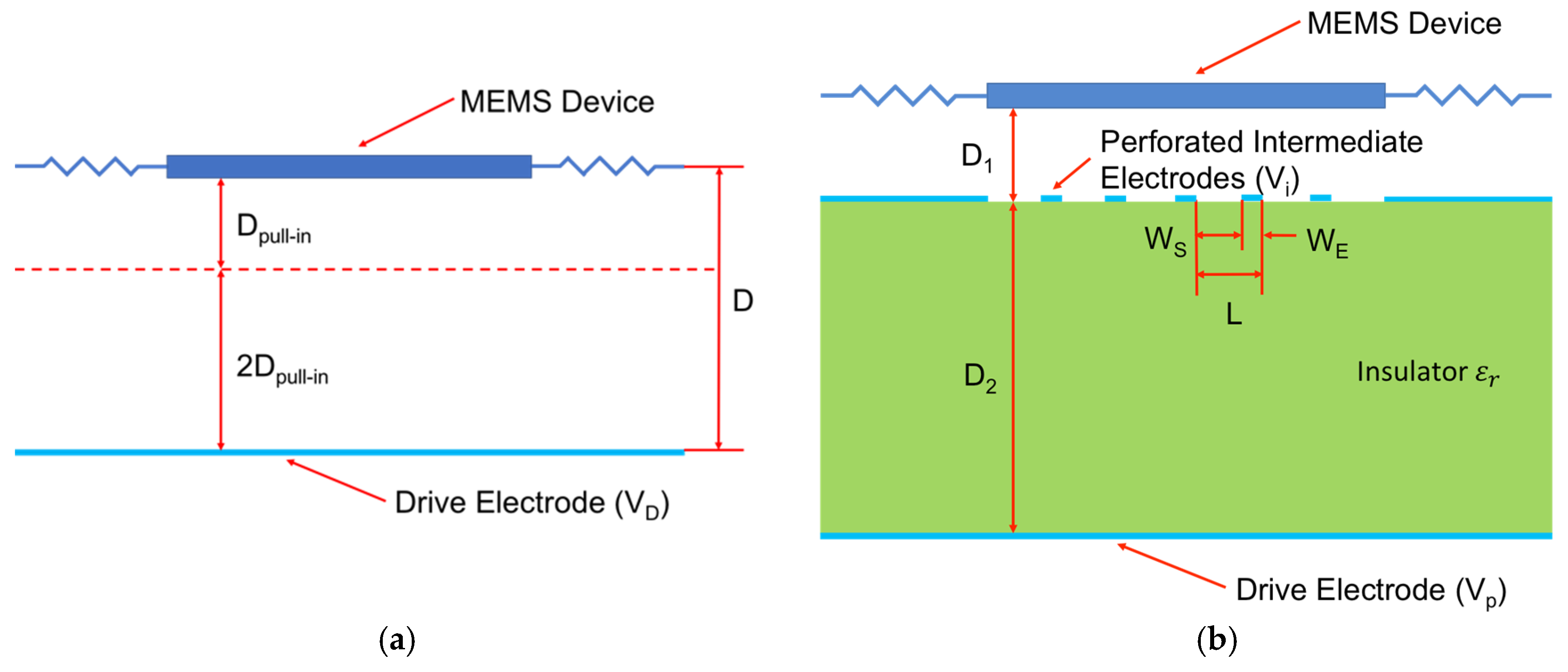
In this paper, we introduce an intermediate electrode between the underlying drive electrode and the above MEMS structure, to modulate the electrostatic force on the MEMS structure. Figure 1a shows a conventional electrostatic actuator, with the MEMS structure placed at a distance D above the drive electrode biased to VD. The controllable stroke Dpull-in occurring at Vpull-in is approximately 1/3 of D. The tri-electrode topology is shown in Figure 1b. The perforated intermediate electrode has solid elements of width WE spaced WS apart, and electrode-spacing pitch L = WE + WS. It is located a distance D1 below the MEMS structure and D2 above the drive electrode (held at a fixed voltage Vp). A modulation voltage Vi is applied on the intermediate electrode.
The electric field modulation enabled by the intermediate electrode in the space D1 is illustrated in the FEM simulation of Figure 2. This simulation has the MEMS held fixed. This figure shows the case of WS = D, WE = 1/6 D, D1 = 7/15 D, and D2 = 7/10 D. In Figure 2a, a Vi = −0.2 Vpull-in is applied on the intermediate electrode, while a Vi = 0.2 Vpull-in is applied in Figure 2b. In both Figure 2a,b, the color gradient represents the potential, while the black arrow shows the electric field. It is clearly seen in Figure 2a that a large portion of the electric field converges on the intermediate electrode, while in Figure 2b the phenomenon is much less significant. The total induced charge on the surface of the MEMS also varies with Vi accordingly. Let us normalize the charge on the MEMS when Vi = 0 V as Q. For the case where Vi = 0.2 Vpull-in, the charge on the MEMS increases to 1.446 Q. While for the case where Vi = −0.2 Vpull-in, the charge on the MEMS decreases to 0.554 Q. This shows that a small fractional voltage Vi can cause a large change on the charge on the MEMS.
2. Simulation Set-Up to Calculate MEMS Displacement
To demonstrate the theory of operation of the new tri-electrode topology, displacement studies were done for both cantilever and square membrane electrostatic actuators. These studies compared the performance of the tri-electrode actuator to that of conventional parallel plate cantilever and membrane actuators, see Figure 3. The dimensional parameters are given in Table 1 (see Figure 1 for parameter definition). For clarity, all parameters are normalized to D, which is the spacing between the drive electrode and the MEMS in the conventional situation.
Simulations of a conventional cantilever actuator were first carried out, in order to obtain the required driving voltage to achieve Dpull-in, and so Vpull-in. For the tri-electrode actuator simulations, first Vp has to be found such that it enables a similar stroke as Dpull-in. Simulations were done with ±Vi set to a fraction of Vpull-in, in order to find the needed drive electrode voltage (Vp) to achieve a maximum controllable stroke of approximately Dpull-in.
3. MEMS Displacement Simulation Results
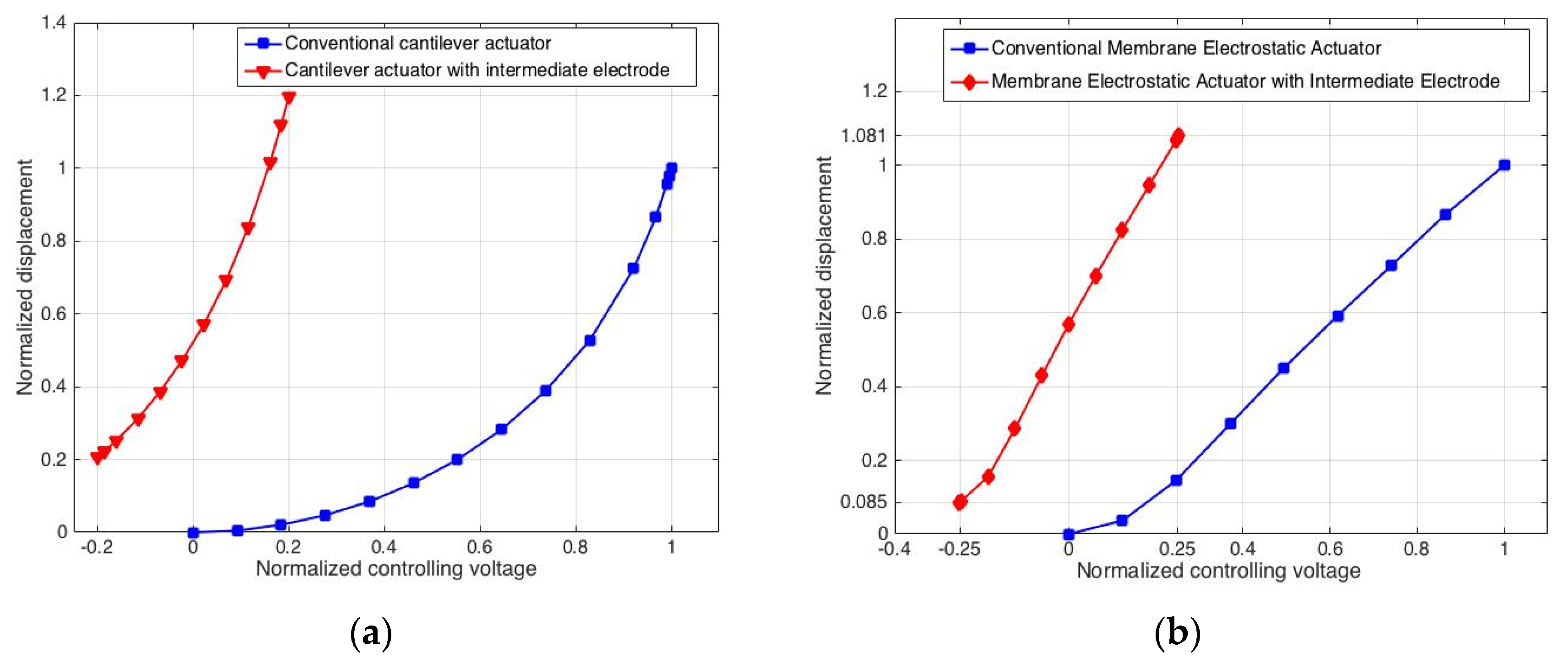
Figure 4a,b compare the tri-electrode topology to conventional parallel plate cantilever and membrane actuators. Displacement is plotted normalized to Dpull-in for the conventional actuators. For the cantilever case, the same controllable stroke can be achieved using the tri-electrode topology with −0.2 Vpull-in < Vi < 0.2 Vpull-in. In the case of the square membrane, −0.25 Vpull-in < Vi < 0.25 Vpull-in is required to realize the same controllable stroke. Also, with this topology, the controllable stroke can reach more than 80% of D1 for the cantilever case, and more than 70% of D1 for the square membrane case. This illustrates that the intermediate electrode does not suffer from pull-in for most of D1.
4. Conclusions
In this paper, we introduce a tri-electrode topology for electrostatic actuators. This topology enables the same controllable stroke as conventional electrostatic actuators, but with greatly reduced control voltage. This is achieved by modulation of the electrostatic force on the MEMS structure by the variable control voltage on the perforated intermediate electrode, as opposed to the drive electrode which has a fixed voltage.
Acknowledgments
This research was financially supported by the Natural Sciences and Engineering Research Council (NSERC) of Canada, and the University of Manitoba Graduate Fellowship (UMGF).
Conflicts of Interest
The authors declare no conflict of interest.
References
- Hung, E.S.; Senturia, S.D. Extending the travel range of analog-tuned electrostatic actuators. J. Microelectromech. Syst. 1999, 8, 497–505. [Google Scholar] [CrossRef]
- Shmulevich, S.; Rivlin, B.; Hotzen, I.; Elata, D. A gap-closing electrostatic actuator with a linear extended range. J. Microelectromech. Syst. 2013, 22, 1109–1114. [Google Scholar] [CrossRef]
- Conrad, H.; Schenk, H.; Kaiser, B.; Langa, S.; Gaudet, M.; Schimmanz, K.; Stolz, M.; Lenz, M. A small-gap electrostatic micro-actuator for large deflections. Nat. Commun. 2015. [Google Scholar] [CrossRef] [PubMed]
- Rosa, M.A.; de Bruyker, D.; Völkel, A.R.; Peeters, E.; Dunec, J. A novel external electrode configuration for the electrostatic actuation of MEMS based devices. J. Micromech. Microeng. 2004, 14, 446–451. [Google Scholar] [CrossRef]
- Sugimoto, T.; Nonaka, K.; Horenstein, M.N. Bidirectional electrostatic actuator operated with charge control. J. Microelectromech. Syst. 2005, 14, 718–724. [Google Scholar] [CrossRef]
- Ren, H.; Wang, W.; Tao, F.; Yao, J. A bi-directional out-of-plane actuator by electrostatic force. Micromachines 2013, 4, 431–443. [Google Scholar] [CrossRef]
- Seeger, J.I.; Crary, S.B. Analysis and simulation of MOS capacitor feedback for stabilizing electrostatically actuated mechanical devices. Trans. Built Environ. 1997, 31. [Google Scholar] [CrossRef]
Figure 1.
(a) Conventional electrostatic actuator; (b) New topology with perforated intermediate electrode.
Figure 1.
(a) Conventional electrostatic actuator; (b) New topology with perforated intermediate electrode.

Figure 2.
The electrical field distribution passing through intermediate electrode perforations: (a) Intermediate electrode voltage Vi = −0.2 Vpull-in; (b) Intermediate electrode voltage Vi = 0.2 Vpull-in.
Figure 2.
The electrical field distribution passing through intermediate electrode perforations: (a) Intermediate electrode voltage Vi = −0.2 Vpull-in; (b) Intermediate electrode voltage Vi = 0.2 Vpull-in.
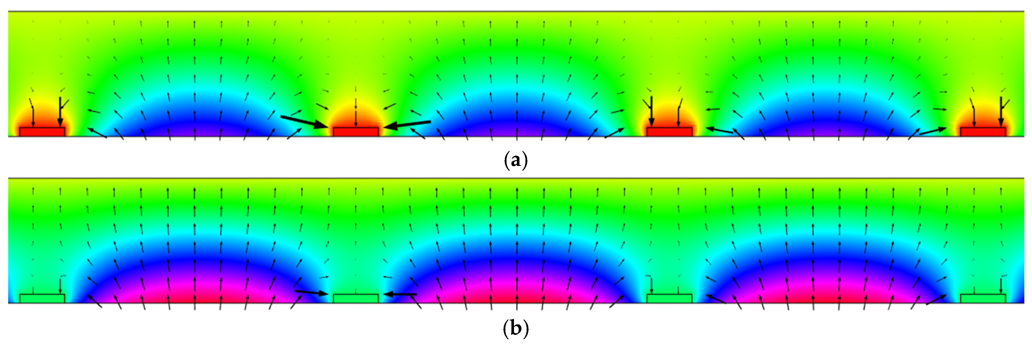
Figure 3.
(a) Simulation structure of the cantilever actuator; (b) Structure of the square membrane actuator.
Figure 3.
(a) Simulation structure of the cantilever actuator; (b) Structure of the square membrane actuator.

Figure 4.
Simulations showing the tri-electrode topology achieving similar stroke as convention electrostatic actuators. (a) Cantilever simulation showing Vi needing to be only −0.2 Vpull-in < Vi < 0.2 Vpull-in; (b) Membrane simulation showing Vi needing to be only −0.25 Vpull-in < Vi < 0.25 Vpull-in.

Table 1.
Structure Parameters Used in Displacement Simulations.
| Parameter | Cantilever Tri-Electrode Actuator | Membrane Tri-Electrode Actuator |
|---|---|---|
| L | 7/6 D | 2/3 D |
| WS | D | 2/5 D |
| WE | 1/6 D | 4/15 D |
| D1 | 7/15 D | 7/15 D |
| D2 | D | D |
Publisher’s Note: MDPI stays neutral with regard to jurisdictional claims in published maps and institutional affiliations. |
© 2017 by the authors. Licensee MDPI, Basel, Switzerland. This article is an open access article distributed under the terms and conditions of the Creative Commons Attribution (CC BY) license (https://creativecommons.org/licenses/by/4.0/).
Share and Cite
MDPI and ACS Style
Zhou, Y.; Shafai, C. Reduction of Electrostatic Control Voltage with a Tri-Electrode Actuator. Proceedings 2017, 1, 282. https://doi.org/10.3390/proceedings1040282
AMA Style
Zhou Y, Shafai C. Reduction of Electrostatic Control Voltage with a Tri-Electrode Actuator. Proceedings. 2017; 1(4):282. https://doi.org/10.3390/proceedings1040282
Chicago/Turabian StyleZhou, Yu, and Cyrus Shafai. 2017. "Reduction of Electrostatic Control Voltage with a Tri-Electrode Actuator" Proceedings 1, no. 4: 282. https://doi.org/10.3390/proceedings1040282