Particle Separation with Deterministic Lateral Displacement (DLD): The Anisotropy Effect †
by
 ,
,
Eloise Pariset
1,2 ,
,
Jean Berthier
1,2,
Catherine Pudda
1,2,
Fabrice Navarro
1,2,
Béatrice Icard
1,2 and
Vincent Agache
1,2,* 1
CEA, LETI, MINATEC Campus, F-38054 Grenoble, France
2
Université Grenoble Alpes, F-38000 Grenoble, France
*
Author to whom correspondence should be addressed.
†
Presented at the Eurosensors 2017 Conference, Paris, France, 3–6 September 2017.
Proceedings 2017, 1(4), 313; https://doi.org/10.3390/proceedings1040313
Published: 18 August 2017
(This article belongs to the Proceedings of Proceedings of Eurosensors 2017, Paris, France, 3–6 September 2017)
Abstract
:Deterministic lateral displacement (DLD) is a passive and label-free microfluidic separation technique with a strong potential for biological sample preparation purposes. Numerical and experimental models have been proposed so far to predict the particle behavior in DLD channels. However, they do not take into account the influence of the pillar anisotropy that induces a secondary pressure gradient in the direction perpendicular to the main flow. The influence of the pillar geometry on the anisotropy magnitude is presented. We show that anisotropy impacts the trajectory of particles in DLD devices and should be included in predictive models for the critical diameter.
1. Introduction
Deterministic lateral displacement (DLD) is a microfluidic particle-separation technique that makes use of successive bifurcations of the laminar flow around an array of regularly arranged pillars. This technique enables to separate nanometer to micrometer-sized particles around a critical diameter called Dc. Several models are available to anticipate the value of Dc according to the geometrical characteristics of the DLD array, such as the pillar inter-spacing, the array rotation angle, the shape and the orientation of the pillars [1,2,3].
DLD technology has been recently widely applied to the separation of biological particles, to purify blood components [4], isolate cancer cells from blood samples [5] and fractionate isolated extracellular vesicles into several subpopulations [6,7].
Recently, the asymmetry of the oblique pillar array was shown to induce symmetry breaking of the flow lane distribution. The flow lane asymmetry results in two critical diameters and an intermediate particle trajectory, called “mixed motion”, in addition to the conventional “zigzag” and “displacement” modes [8,9]. The magnitude of anisotropy was quantified by Vernekar et al. [10] by considering the undesired lateral pressure gradient in DLD channels, according to the array rotation angle and the aspect ratio of the oblique primitive lattice cell. The anisotropy effect was experimentally proved to change the critical diameter and induce unexpected particle trajectories. Asymmetrical DLD lattice cells were recently exploited to increase the separation efficiency of red blood cells [11].
As the DLD anisotropy effect appears to be a key parameter to optimize particle separation, the influence of several geometrical parameters on the anisotropy magnitude is presented here. In particular, the pillar orientation is shown to be a dominant factor that has not been considered so far. The influence of the anisotropy effect on the particle trajectory is illustrated and provides perspectives for tunable multi-separation DLD devices.
2. Materials and Methods
In order to separate micrometer to nanometer-sized particles, the required DLD pillars have micrometric dimensions. The fabrication process flow was based on 200 mm silicon microtechnologies.
Imaging was performed by epifluorescence microscopy to visualize the trajectory of monodisperse fluorescent polystyrene particles (ThermoFisher Scientific, Fluoro-Max Dyed Green Aqueous Fluorescent Particles) flowing in the DLD channel. The chips were integrated onto a plastic cartridge with plug and play tubing connectors. Fluids were actuated by a pressure-based flow controller (Fluigent, MFCS-EZ) in order to obtain flow rates of about 100 µL/min in the pillar array.
Finite element modeling with COMSOL Multiphysics® was used to model the particle behavior in DLD channels. The hydrodynamics of the carrier fluid was first computed. To obtain the particle trajectory, the Newton equation was solved for each particle, taking into account inertia, gravity and drag force. The COMSOL module “Particle Tracing” needed refinements to take into account the wall-exclusion effect. A rebound condition—based on the distance from the particle barycenter to the wall—was set up on any solid boundary (pillars and channel walls), so that the particle envelope did not intersect the wall surface.
3. Results
3.1. Numerical and Experimental Validation of DLD Separation
In order to model DLD particle separation with a finite element method, the steric effect of the particles was considered thanks to a computed wall-distance map. The distance from each point of the computational domain to the boundary was given by the Eikonal equation [12]. In case of a particle-wall contact (when the particle-wall distance is equal to the particle radius and its velocity is directed towards the wall), a rebound condition was set up:
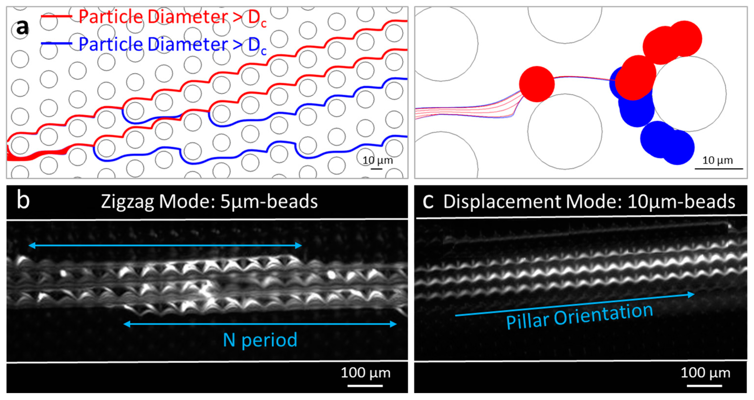
Figure 1a shows two populations of particles of different sizes (diameters 7 and 7.2 µm), transported by a carrier fluid, moving around circular pillars (inter-pillar spacing = 15 µm). The DLD separation around the critical diameter is well modeled, at the precision of the distance field.
Figure 1b,c show experimental observations of the zigzag mode and the displacement mode in a DLD device with expected critical diameter around 5 µm [2]. The trajectory of fluorescent particles confirms that 5 µm-beads follow a zigzag mode (periodic pattern with a globally straight path), while 10 µm-beads follow a displacement mode (constant deviation of the particle flow, oriented towards the direction of the pillar row). Thus, the two conventional trajectory modes in DLD—zigzag and displacement—are verified both experimentally and numerically.
3.2. Influence of the Anisotropy Effect on the Particle Separation
In DLD devices with slanted elongated pillars, a third mode of trajectory is observed in the numerical calculation (Figure 2). Particles larger than Dc still follow a displacement mode, but particles smaller than Dc are oriented downwards, in the direction of pillars, while zigzagging between pillar rows. Thus, the pillar shape and orientation can induce such a large anisotropy that the particle trajectory is modified.
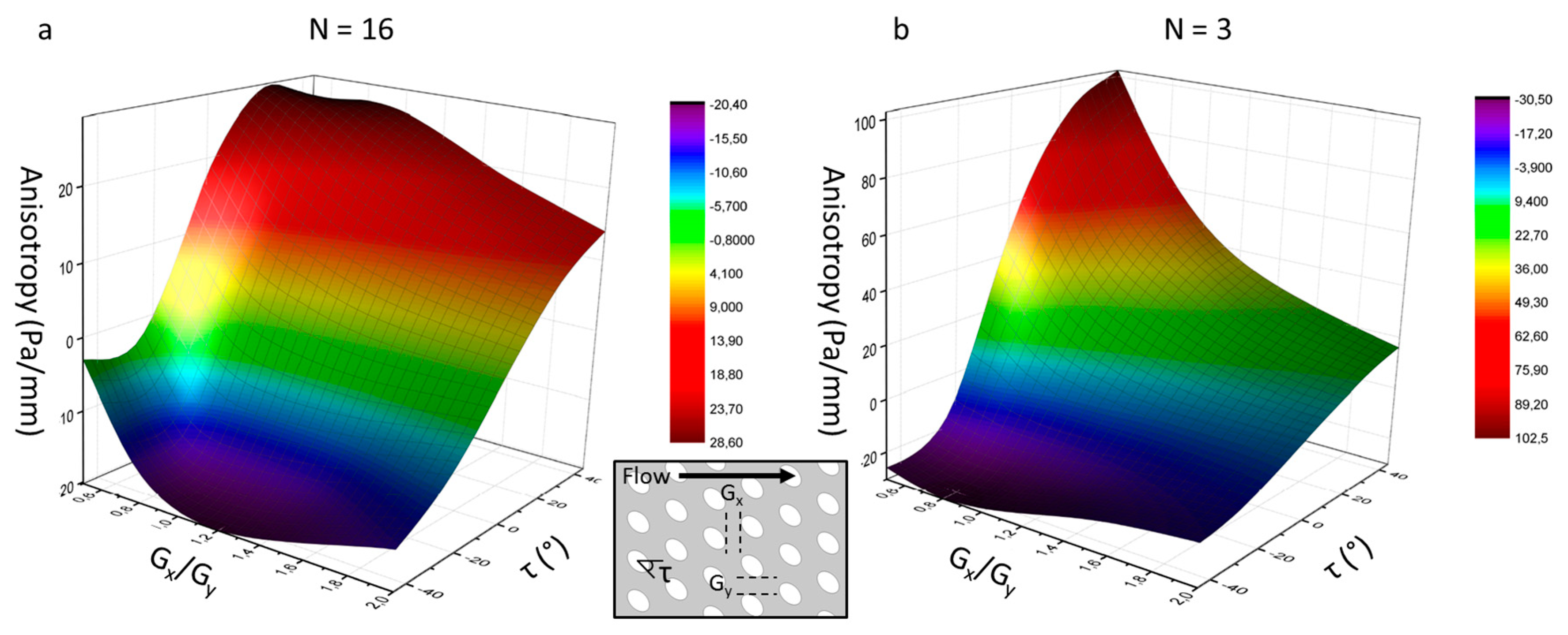
3.3. Parametric Study of the Anisotropy Magnitude
In order to anticipate the anisotropy effect in DLD arrays, the magnitude of anisotropy was quantified according to three geometrical parameters of ellipsoidal pillars (represented in Figure 3): the ratio of lateral-gap to downstream-gap (Gx/Gy), the pillar slant angle (τ) and the array period (N). The anisotropy is defined as the lateral pressure gradient in the channel cross direction [10].
The reported influence of the inter-pillar gap ratio (Gx/Gy) and the array period (N) on the anisotropy magnitude is verified for non-slanted pillars (τ = 0) [10]: anisotropy increases when Gx/Gy and N decrease. Figure 3 introduces a new important dimension, which is is the pillar slant angle (τ). Positive angles (pillars oriented upwards) generate positive anisotropy, while negative angles (pillars oriented downwards) lead to negative anisotropy. For downward-oriented pillars, a minimum anisotropy value is encountered at specific Gx/Gy ratios (called RG), whereas for upward-oriented pillars, the anisotropy continuously grows when Gx/Gy decreases. Above RG, the anisotropy becomes more negative when Gx/Gy decreases. However, below RG, the pillars are too close to enable streamline zigzag across successive rows and streamlines are focused in the upward array direction, which makes the anisotropy become less negative.
4. Discussion
In this work, a new parameter is introduced to take into account the anisotropy in DLD channels: the slant angle of elongated pillars (τ). In ellipsoidal pillar arrays, this new parameter brings an important contribution to anisotropy—in addition to the gap ratio and the array period [10]—in the anisotropy magnitude. The parametric study we have performed could be generalized to other asymmetric pillar shapes, like foils.
It is demonstrated that the particle trajectory is influenced by the lateral pressure gradient in highly anisotropic DLD arrays. Therefore, the critical diameter is modulated by the anisotropy magnitude, but this effect is not included in DLD models so far. Tunable multi-separation devices could be designed by changing the slant angle of elongated pillars in successive DLD areas. Moreover, the DLD separation efficiency could be greatly increased by orienting elongated pillars in the opposite direction to the pillar array. In this case, particles following a zigzag mode are oriented downwards, which separates them even better from the displaced particles.
Acknowledgments
This work was supported by a CFR CEA grant for Ph.D. funding, and the FET Proactive H2020 Viruscan project (number 731868).
Conflicts of Interest
The authors declare no conflict of interest.
References
- Inglis, D.W.; Davis, J.A.; Austin, R.H.; Sturm, J.C. Critical particle size for fractionation by deterministic lateral displacement. Lab. Chip 2006, 6, 655–658. [Google Scholar] [CrossRef] [PubMed]
- Loutherback, K.; Chou, K.S.; Newman, J.; Puchalla, J.; Austin, R.H.; Sturm, J.C. Crossing microfluidic streamlines to lyse, label and wash cells. Microfluid. Nanofluidics 2010, 9, 1143–1149. [Google Scholar] [CrossRef]
- Wei, J.; Song, H.; Shen, Z.; He, Y.; Xu, X.; Zhang, Y.; Li, B.N. Numerical Study of Pillar Shapes in Deterministic Lateral Displacement Microfluidic Arrays for Spherical Particle Separation. IEEE Trans. Nanobiosci. 2015, 14, 660–667. [Google Scholar] [CrossRef] [PubMed]
- Kim, B.; Choi, Y.J.; Seo, H.; Shin, E.-C.; Choi, S. Deterministic Migration-Based Separation of White Blood Cells. Small 2016, 12, 5159–5168. [Google Scholar] [CrossRef] [PubMed]
- Okano, H.; Konishi, T.; Suzuki, T.; Suzuki, T.; Ariyasu, S.; Aoki, S.; Abe, R.M. Separation of viable and nonviable mammalian cells using a deterministic lateral displacement microfluidic device. Hayase Biomed. Microdevices 2015, 17, 59. [Google Scholar] [CrossRef] [PubMed]
- Wunsch, B.H.; Smith, J.T.; Gifford, S.M.; Wang, C.; Brink, M.; Bruce, R.L.; Austin, R.H.; Stolovitzky, G.; Astier, Y. Nanoscale lateral displacement arrays for the separation of exosomes and colloids down to 20nm. Nat. Nanotechnol. 2016, 11, 936–940. [Google Scholar] [CrossRef] [PubMed]
- Pariset, E.; Agache, V.; Millet, A. Extracellular Vesicles: Isolation Methods. Adv. Biosyst. 2017, 1, 1700040. [Google Scholar] [CrossRef] [PubMed]
- Kulrattanarak, T.; van der Sman, R.G.M.; Schroën, C.G.P.H.; Boom, R.M. Analysis of mixed motion in deterministic ratchets via experiment and particle simulation. Microfluid. Nanofluidics 2010, 10, 843–853. [Google Scholar] [CrossRef]
- Kulrattanarak, T.; van der Sman, R.G.M.; Lubbersen, Y.S.; Schroën, C.G.P.H.; Pham, H.T.M.; Sarro, P.M.; Boom, R.M. Mixed motion in deterministic ratchets due to anisotropic permeability. J. Colloid Interface Sci. 2011, 354, 7–14. [Google Scholar] [CrossRef] [PubMed]
- Vernekar, R.; Krüger, T.; Loutherback, K.; Morton, K.; Inglis, D. Anisotropic permeability in deterministic lateral displacement arrays. Phys. Fluid Dyn. 2016, arXiv:1610.08427v1. [Google Scholar] [CrossRef] [PubMed]
- Zeming, K.K.; Salafi, T.; Chen, C.-H.; Zhang, Y. Asymmetrical Deterministic Lateral Displacement Gaps for Dual Functions of Enhanced Separation and Throughput of Red Blood Cells. Sci. Rep. 2016, 6, 22934. [Google Scholar] [CrossRef] [PubMed]
- Bronstein, A.M.; Bronstein, M.M.; Kimmel, R. Generalized multidimensional scaling: A framework for isometry-invariant partial surface matching. J. Comput. Phys. 2007, 225, 771–784. [Google Scholar] [CrossRef]
Figure 1.
(a) Finite element modeling of the DLD separation; Epifluorescence microscopy images of the trajectory of 5 µm (b) and 10 µm (c) polystyrene fluorescent beads in a DLD device of triangular pillars (inter-pillar spacing = 20 µm and array period = 13).
Figure 1.
(a) Finite element modeling of the DLD separation; Epifluorescence microscopy images of the trajectory of 5 µm (b) and 10 µm (c) polystyrene fluorescent beads in a DLD device of triangular pillars (inter-pillar spacing = 20 µm and array period = 13).

Figure 2.
Trajectory modeling of 2 µm, 4 µm and 6 µm beads in an array of slanted elipsoidal pillars.
Figure 2.
Trajectory modeling of 2 µm, 4 µm and 6 µm beads in an array of slanted elipsoidal pillars.
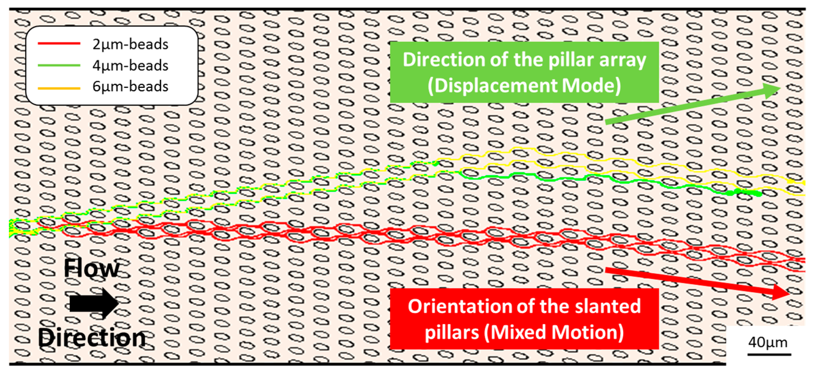
Figure 3.
Evolution of the anisotropy with the ratio of lateral-gap to downstream-gap (Gx/Gy) and the pillar slant angle (τ) for an array period N = 16 (a) and N = 3 (b).
Figure 3.
Evolution of the anisotropy with the ratio of lateral-gap to downstream-gap (Gx/Gy) and the pillar slant angle (τ) for an array period N = 16 (a) and N = 3 (b).

Publisher’s Note: MDPI stays neutral with regard to jurisdictional claims in published maps and institutional affiliations. |
© 2017 by the authors. Licensee MDPI, Basel, Switzerland. This article is an open access article distributed under the terms and conditions of the Creative Commons Attribution (CC BY) license (https://creativecommons.org/licenses/by/4.0/).
Share and Cite
MDPI and ACS Style
Pariset, E.; Berthier, J.; Pudda, C.; Navarro, F.; Icard, B.; Agache, V. Particle Separation with Deterministic Lateral Displacement (DLD): The Anisotropy Effect. Proceedings 2017, 1, 313. https://doi.org/10.3390/proceedings1040313
AMA Style
Pariset E, Berthier J, Pudda C, Navarro F, Icard B, Agache V. Particle Separation with Deterministic Lateral Displacement (DLD): The Anisotropy Effect. Proceedings. 2017; 1(4):313. https://doi.org/10.3390/proceedings1040313
Chicago/Turabian StylePariset, Eloise, Jean Berthier, Catherine Pudda, Fabrice Navarro, Béatrice Icard, and Vincent Agache. 2017. "Particle Separation with Deterministic Lateral Displacement (DLD): The Anisotropy Effect" Proceedings 1, no. 4: 313. https://doi.org/10.3390/proceedings1040313