MEMS Inertial Switch for Military Applications †


1
Agency for Defence Development, Daejeon, Korea
2
Micro-infinity Co. Ltd., Suwon, Korea
*
Author to whom correspondence should be addressed.
†
Presented at the Eurosensors 2017 Conference, Paris, France, 3–6 September 2017.
Proceedings 2017, 1(4), 343; https://doi.org/10.3390/proceedings1040343
Published: 9 August 2017
(This article belongs to the Proceedings of Proceedings of Eurosensors 2017, Paris, France, 3–6 September 2017)
Abstract
:We developed a MEMS inertial switch (hereafter, the switch) for an ignition system of missiles. The developed switch consists of four folded beams and a plate suspended by the beams, analogous to a well-known spring-mass system. The plate and four beams compose a single body, which is made from single crystalline silicon wafers by deep reactive ion etching techniques. This process gives high thermal stability and stress-free structure. The switching, either open or close a conductive path, is achieved by the movement of the plate suspended with four folded beams when the acceleration exceeds a predetermined threshold. With a spinning-rate table, the function of the switch was tested at various revolution speeds. The test results are compared with the calculation results by our analytical model.
1. Introduction
Most missiles have a safe-and-arm device (SAD) to prevent accidental or unintentional firing of a rocket motor. As critical components of the SAD, various types of inertial switches have been used for decades. In this application in which dimensional constraints are tightly given, sizing down of the switch is important. Using MEMS would be a good choice because it can be easily accommodated in a small space. For this reason, the demand of MEMS inertial switches has been increased in this field. The function of the switches is mainly to either open or close a path of ignition systems. That is, the switch opens ignition circuits in a safe state while, in an arm state, it closes the circuits to allow passing firing currents to an igniter. The switching to a turn-on state is achieved when acceleration of the missile exceeds a predetermined level. For SAD applications, the acceleration level triggering the MEMS switch is usually about 10 g lower than that of other uses. Although there has been growing interest in the MEMS inertial switch [1,2,3,4], reports on the switches capable of acting at such a relative low acceleration are scanty because of the difficulty associated with their designing and manufacturing [5].
We developed the MEMS switch for the SAD of cold launched missiles. The switch developed consists of a plate (mass) suspended by 4 folded beams (spring), the switching of which is achieved by inertial movement of the plate. Our switch is similar to the horizontal inertial switch designed by Massad et al. [6] in terms of configuration, except that the switching is achieved by an acceleration. The goal of the present work is to develop the capability of switching at a low-g level (about 10 g). To this end, we employ a finite element method in ANSYS Workbench to determine the design parameters of the switch. A challenge in the development of a low-g MEMS inertial switch is to make it withstand unintentional shock (ranging hundreds of g) from harsh military environments. In the design stage, this risk was also checked by the use of the finite element model, i.e., the stresses induced at each part of the switch were calculated in several shock conditions. With some proto-type switches, we tested their switching functions by the spin-rate table. The test results were compared with the results of our analytical model for switching performance, which were iteratively used to obtain optimal design parameters.
2. Design and Fabrication of MEMS Switch
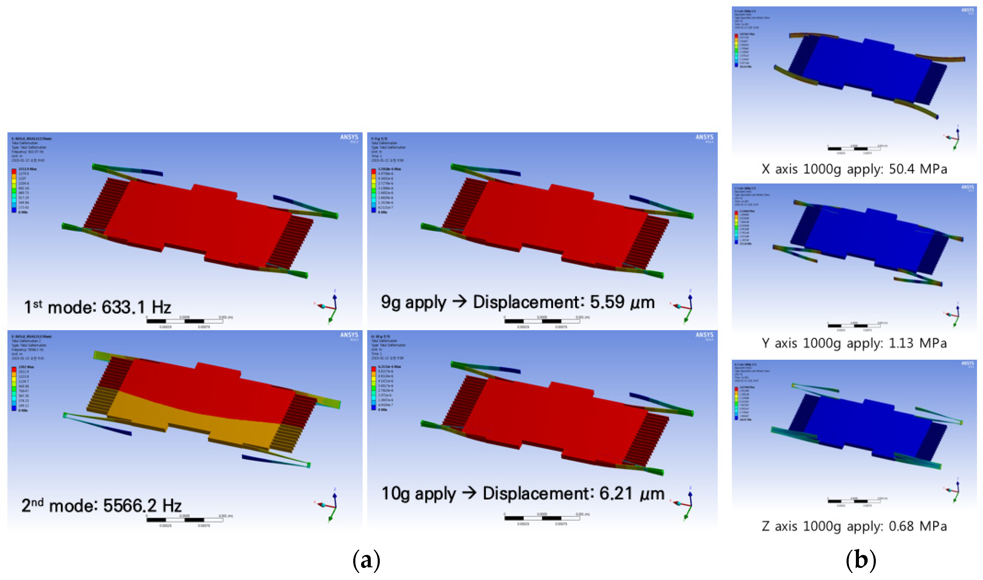
Figure 1 illustrates the MEMS inertial switch designed with a threshold of 10 g, which is operated only in one direction. Three parameters are identified to be important in design: the mass of the plate, the elasticity of four folded beams, and the distance between the contacts. In practice, the mass of the plate is constrained by the size of a chip in wafer. The beams, acting as a spring, was designed to be folded four times to obtain greater displacement and better linearity. Figure 2a shows the results of finite element analysis, which is the typical example that the displacement of the plate was 6.21 μm when 10 g is applied. This kind of results allow us to decide values of the important design parameters, for instance, the distance between the contacts was 6 μm.
The switch can undergo abnormally higher shock in military uses. The robustness of the switch, under the circumstance, was also checked by the finite element model. As can be seen in Figure 2b, when applied a 1000 g shock, the calculated stress was not more than 1.13 GPa for Y-axis, which is almost a sixth of the facture strength of silicon, 7 GPa.
The fabrication flow of the switch is shown in Figure 3. In the figure, the three terms are used to classify wafer layers: “base glass” for the bottom layer; “device wafer” for the middle layer; and “cap glass” for the top layer. During fabrication, the switch is protected from contamination by a wafer level packaging. This packaging process enhances the integrity of the switch because it keeps the plate from moving by unintentional shock or vibration. Figure 4 displays a SEM image of the fabricated switch.
3. Test and Analysis Results
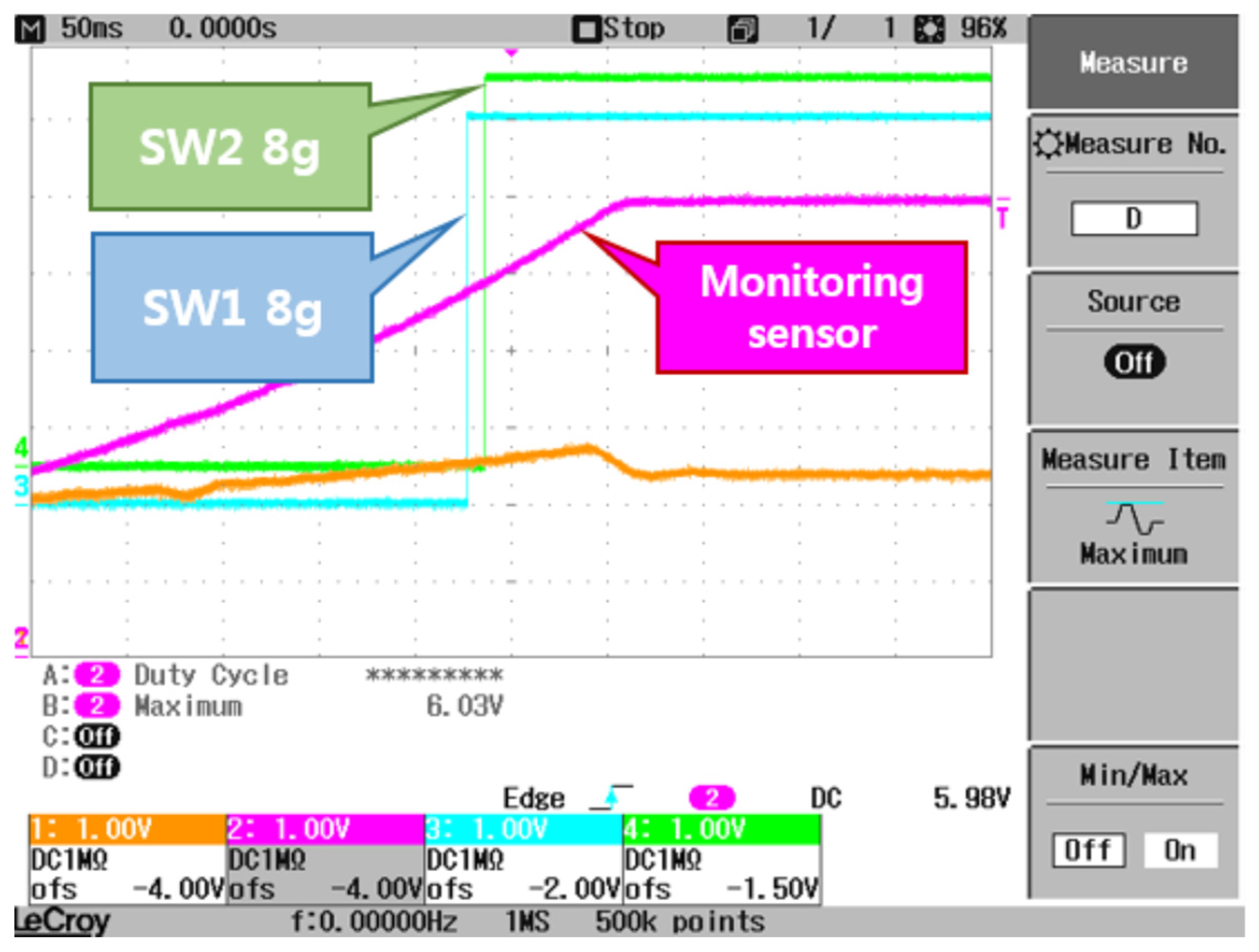
The switching function was examined with the spinning-rate table (Acutronic 10 Axis Rate Table AC1120) that can simulate acceleration. A typical test result is given in Figure 5 that the vertical axis is the voltage between the two contacts and the horizontal axis is the applied acceleration. In this test, the acceleration level was increased to 12 g, which is controlled by a revolution speed of the spin table. The threshold level of switching is determined if the voltage rises abruptly during step increases of acceleration. It was found that the switching threshold level of the developed switch was 8 g (see Figure 5).
An analytical model was developed to predict the switching performance. The present MEMS switch can be modeled as a single degree of freedom spring-mass-damper-contact system. The governing differential equation of the system is given by
where m is the mass, c the damping factor, k the stiffness, x the displacement of mass, and fe the electric force between the contacts. The last term here represents the force owing to electric power supplied to detect whether the two contacts are open or close, which can be expressed as
where Vsense is the supplied voltage for detecting, A the area of the contact, x the gap between the two contacts, and the dielectric constant of the air between the two contacts. The spring constant of a folded beam is expressed as below:
where E is Young’s modulus, h the thickness, w the width, and l the length of a spring. Once the values of Equations (2) and (3) are obtained, Equation (1) can then be solved by numerical schemes such as the Runge-Kutta method. The calculation results, the displacement of the plate as a function time at various acceleration levels, were compared with the test results. The agreement between the two results is rather good although the comparison results are not presented here.
4. Conclusions
A MEMS inertial switch for missile ignition systems was developed. The special feature of this switch is that the switching occurs at low-g levels, i.e., the threshold acceleration level is no more than 10 g. The switch consists of a plate and the four folded beams corresponding respectively to a mass and a spring, the switching of which is achieved by inertial movement of the plate. In fabrication, a wafer-level-packaging process was adopted to make the switch robust against harsh military environments. The switching function was examined with a spinning-rate table, the result of which agree with the analytical model developed to predict switching performance. This switch can be applicable to a safe-and-arm device of the rocket motor ignition system for cold-launched missiles.
Conflicts of Interest
The authors declare no conflict of interest.
References
- Loke, Y.; Mckinnon, G.; Brett, M.J. Fabrication and Characterization of Silicon Micro Machined Threshold Accelerometer. Sens. Actuators A Phys. 1991, 29, 235–240. [Google Scholar] [CrossRef]
- Tonnesen, T.; Ludtke, O.; Noetzel, J.; Binder, J.; Mader, G. Simulation, Design and Fabrication of electroplated acceleration switches. J. Micromech. Microeng. 1997, 7, 237–239. [Google Scholar] [CrossRef]
- Lee, J.I.; Song, Y.; Jung, H.K.; Choi, J.; Eun, Y.; Kim, J. Carbon Nanotubes Integrated Inertial Switch for Reliable Detection of Threshold Acceleration. In Proceedings of the Solid State Sensors, Actuators and Microsystems Conference, Beijing, China, 5–9 June 2011; pp. 711–714. [Google Scholar]
- Michaelis, S.; Timme, H.J.; Wycisk, M.; Binder, J. Additive Electroplating Technology as a post CMOS process for the production of MEMS acceleration threshold switches for transportation application. J. Micromech. Microeng. 2000, 10, 120–123. [Google Scholar] [CrossRef]
- Kim, H.; Jang, Y.; Kim, J. MEMS Acceleration Switch with Bi-directional Tunable Threshold. Sens. Actuators A Phys. 2014, 208, 120–129. [Google Scholar] [CrossRef]
- Massad, J.E.; Sumali, H.; Epp, D.S.; Dyck, C.W. Modeling, Simulation and Testing of the Mechanical Dynamics of an RF Mems Switch. In Proceedings of the 2005 International Conference on MEMS, NANO and Smart Systems, Banff, AB, Canada, 24–27 July 2005; pp. 237–240. [Google Scholar]
Figure 1.
Schematic of MEMS inertial switch.
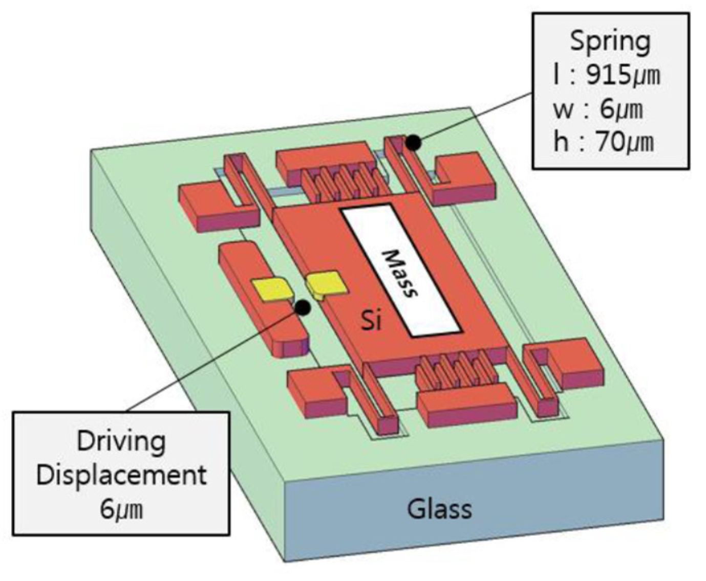
Figure 2.
(a) Simulation results of MEMS switching; (b) FEM analysis of MEMS switch

Figure 3.
Fabrication process of MEMS switch.
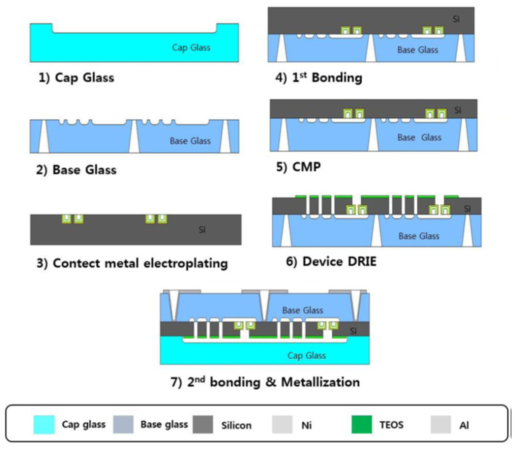
Figure 4.
SEM image of MEMS switch.
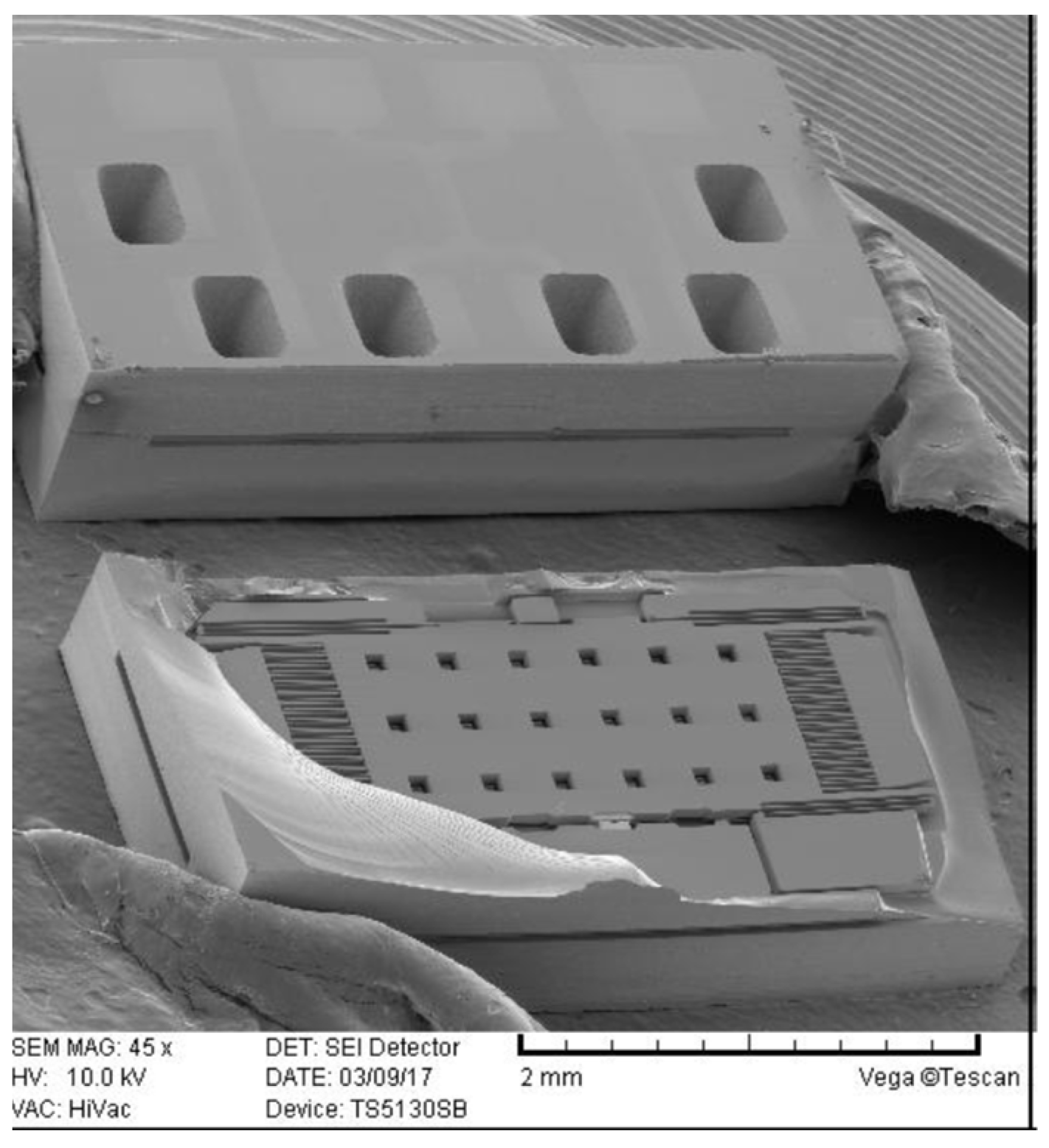
Figure 5.
MEMS switch test result.

Publisher’s Note: MDPI stays neutral with regard to jurisdictional claims in published maps and institutional affiliations. |
© 2017 by the authors. Licensee MDPI, Basel, Switzerland. This article is an open access article distributed under the terms and conditions of the Creative Commons Attribution (CC BY) license (https://creativecommons.org/licenses/by/4.0/).
Share and Cite
MDPI and ACS Style
Lee, H.-N.; Jang, S.-G.; Lee, S.; Lee, J.-S.; Hwang, Y.-S. MEMS Inertial Switch for Military Applications. Proceedings 2017, 1, 343. https://doi.org/10.3390/proceedings1040343
AMA Style
Lee H-N, Jang S-G, Lee S, Lee J-S, Hwang Y-S. MEMS Inertial Switch for Military Applications. Proceedings. 2017; 1(4):343. https://doi.org/10.3390/proceedings1040343
Chicago/Turabian StyleLee, Hyo-Nam, Seung-Gyo Jang, Sungryeol Lee, Jeong-Sun Lee, and Young-Suk Hwang. 2017. "MEMS Inertial Switch for Military Applications" Proceedings 1, no. 4: 343. https://doi.org/10.3390/proceedings1040343