A Comb-Based Capacitive MEMS Microphone with High Signal-to-Noise Ratio: Modeling and Noise-Level Analysis †


1
Institute for Physics of Electrotechnology at Technical University of Munich, 80333 Munich, Germany
2
Infineon Technologies AG, 85579 Neubiberg, Germany
*
Author to whom correspondence should be addressed.
†
Presented at the Eurosensors 2017 Conference, Paris, France, 3–6 September 2017.
Proceedings 2017, 1(4), 346; https://doi.org/10.3390/proceedings1040346
Published: 8 August 2017
(This article belongs to the Proceedings of Proceedings of Eurosensors 2017, Paris, France, 3–6 September 2017)
Abstract
:We present a physics-based system-level model for optimizing a novel comb-based capacitive MEMS microphone towards high signal-to-noise ratios. The model includes non-linear coupling effects between the electrodes as well as the physical dependencies on relevant design parameters, thus enabling predictive statements w.r.t. the device performance. It is calibrated and validated by finite element simulations and laser Doppler vibrometer measurements of first prototypes. Being formulated as a generalized Kirchhoffian network, it can be implemented in a standard circuit simulation tool. The predicted signal-to-noise ratio of this concept reaches up to 78 dB(A), which significantly exceeds state-of-the-art devices.
1. Motivation and Description of Device Concept
Conventional backplate-based silicon microphones have reached a mature state in the market, especially in mobile communication applications. Consisting of a moveable membrane, which detects incident acoustical waves by the capacitance change w.r.t. a stiff, perforated backplate [1], they suffer from high fluidic noise, which limits the signal-to-noise-ratio (SNR) achievable by this technology. In order to overcome this constraint, a novel microphone concept was recently introduced in [2]. Thereby radially aligned comb fingers are attached to the bottom side of a moveable membrane (see Figure 1).
In conjunction with a spidernet-like stator fixed to the substrate underneath, they form an interdigitated comb-system. This specific design as a backplate-free device is expected to exhibit lower losses and, thus, higher SNR compared to classical microphones.
First system-level models of this design are presented in [2,3], describing the microphone as a system of two coupled one-dimensional harmonic oscillators. Membrane and stator are both considered moveable and couple via electrostatic and fluidic damping forces. However, up to now, only linearized operation around a fixed working point (e.g., fixed fluidic damping coefficient taken from FE-simulation) could be simulated. In this work, the model is extended to a generalized, physics-based description including the dependencies on the relevant design parameters for all involved coupling mechanisms, thus building the basis for predictive simulation and optimization with respect to the key figures “noise” and “SNR.”
2. Physics-Based Modeling of Electrostatic Force and Fluidic Damping
The microphone model is intended for system-level simulation covering the interplay of the transducer, package and read-out electronics. Hence, the model complexity for each subsystem has to be reduced. For the comb read-out, periodic boundary conditions are applied and only the two-dimensional cut as shown in Figure 2a and Figure 3a is considered for deriving the electrostatic and fluidic subdomain models. Subsequently the 2D models are extruded to model the full 3D operation.
2.1. Capacitive Transducer Model
The capacitive transducer model is built by summing up the electric capacitance between membrane and stator () and the electric capacitance between the comb fingers (), both depending on the vertical displacement :
Here, is the permittivity, the lateral width of the stator comb, and the lateral distance between motor and stator combs. Fringing fields are taken into account introducing an effective overlap of the combs , where is extracted from finite element simulation (FE). The total active capacitance of the microphone is obtained by multiplying Equation (1) with the number of comb-systems (N), the radial length of combs (L) and a factor of 2 for symmetry reasons. Figure 2c shows that the resulting model exhibits an accuracy of above 95% for parameter variations within the relevant design space.
2.2. Fluidic Damping Model
Fluidic FE simulations have been carried out in order to identify the most dominant contributions to the fluidic damping. The air flow in the symmetric basic cell of the comb structure is depicted in Figure 3a. It is dominated by the broader channel between two neighboring comb systems (“spacing path”), allowing to neglect the slide-film damping effects in the “comb-path”. The contributions to the damping can be modeled applying a fluidic network consisting of a Hagen-Poiseuille flow in the channel , a viscous orifice flow , and a transit region represented by . Analytical formulations for the network components can be derived from the Stokes equation and e.g., be found in [4]. Using a correction structurally similar to to take into account the residual flow through the “comb-path” , the fluidic damping model can be formulated as:
Here, is the viscosity of air and the mean distance of two neighboring comb cells. The correction factor is extracted from FE-Simulation. The resulting damping forces obtained by Equation (2) show an overall precision of 97% compared to FE-Simulations (see Figure 3c). Finally, the total damping force is obtained by extruding this model in radial direction and multiplying Equation (2) by the number of comb-systems and a factor of 2 for symmetry reasons.
2.3. Verification of the System-Level Model
In order to validate the above described models, they are implemented into a system-level model derived in [2], allowing for comparison of the membrane frequency response to data recorded by laser Doppler (LDV) vibrometry of first prototypes. The simulations reproduce the amplitude as well as the resonance frequencies and their peak widths (which is equivalent to the Q factor) for varying bias voltages with excellent agreement (Figure 4a). This proves the quality of the derived submodels as well as the quality of total system-level model including the couplings between the single energy domains. Comparison of measured and simulated amplitudes and Q factors for different design variants are listed in Table 1. The accuracy of over 94% for all design variants validates the 3D extrusion of the subdomain models and demonstrates the predictive power of the system model.
3. Noise and SNR
The validated, physics-based system-level model can now be applied to optimize the device concept w.r.t. its total SNR. In order to get the highest dynamic range and a linear sensor response, an overlap of the combs of 50% is suggested, which has not been technologically realized yet. Figure 4b shows the simulated spectral noise density and discriminates the contributions of different parts of the device to the overall noise level, considering a fully packaged microphone as described in [2]. It revealed that the proposed variant yields very promising SNR values of up to 78 dB(A), which is exceeding state-of-the art microphones. The simulated sensitivity of the microphone amounts to −45.2 . Although the noise contribution of the ASIC is neglected here, the results indicate the potential and the promising perspective of the device for further investigations.
4. Conclusions
We presented a physics-based and hence predictive system-level model describing the electrode coupling in comb-based capacitive MEMS-microphones designed for high SNR. All subdomain models are validated by FE-simulations and measurements. The system model is applied to investigate the potential of the device w.r.t. the obtainable SNR. Simulations of a design variant with 50% overlap of the comb fingers reveal a very promising SNR of 78 dB(A) and provide the design space for the technological realization of optimized devices.
Acknowledgments
This project has received funding from the Electronic Component Systems for European Leadership Joint Undertaking (Grant Agreement No. 692480).
Conflicts of Interest
The authors declare no conflict of interest.
References
- Dehé, A.; Wurzer, M.; Füldner, M.; Krumbein, U. The Infineon Silicon MEMS Microphone. In Proceedings of the SENSOR 2013, Nürnberg, Germany, 14–16 May 2013; pp. 95–99. [Google Scholar]
- Manz, J.; Bosetti, G.; Dehé, A.; Schrag, G. A Novel Silicon “Star-Comb” Microphone Concept for Enhanced Signal-to-noise Ratio: Modeling, Design and First Prototype. In Proceedings of the Transducers 2017, Kaohsiung, Taiwan, 18–22 June 2017. [Google Scholar]
- Bosetti, G.; Manz, J.; Schrag, G.; Dehé, A. Modeling of an Out-of-plane Capacitive MEMS Transducer with Dynamically Coupled Electrodes. In Proceedings of the DTIP 2017, Bordeaux, France, 29 May–1 June 2017; pp. 29–33. [Google Scholar]
- Niessner, M.; Schrag, G. Mixed-Level Approach for the Modeling of Distributed Effects in Microsystems, in System-Level Modeling of MEMS; Wiley-VCH: Weinheim, Germany, 2013; pp. 163–189. [Google Scholar]
Figure 1.
(a) Schematic view of the microphone introduced in [2]. Radially aligned combs attached to the membrane form the interdigitated comb-structure with respect to the stator; (b) Bottom view of the comb structure (SEM picture of a prototype); (c) Cross-sectional view of the comb-system.
Figure 1.
(a) Schematic view of the microphone introduced in [2]. Radially aligned combs attached to the membrane form the interdigitated comb-structure with respect to the stator; (b) Bottom view of the comb structure (SEM picture of a prototype); (c) Cross-sectional view of the comb-system.

Figure 2.
(a) Electrostatic potential inside the comb structure as obtained by FE-simulation; (b) Effective comb overlap accounting for fringing-field effects (c) Capacitance of comb fingers vs. vertical deflection: comparison between compact model and data from electrostatic FE simulations.
Figure 2.
(a) Electrostatic potential inside the comb structure as obtained by FE-simulation; (b) Effective comb overlap accounting for fringing-field effects (c) Capacitance of comb fingers vs. vertical deflection: comparison between compact model and data from electrostatic FE simulations.
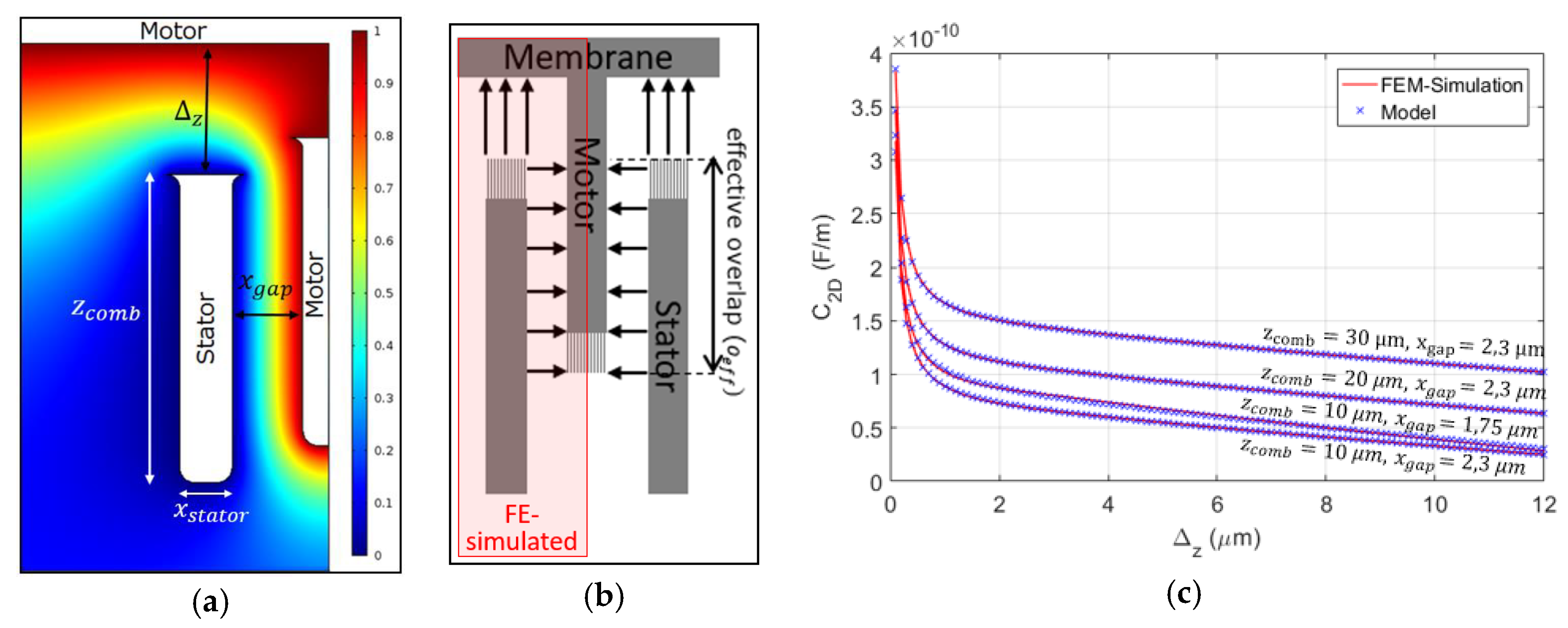
Figure 3.
Derivation of the viscous damping model: (a) Fluid flow induced by moving membrane as obtained by FE simulations; (b) System-level model describing the fluidic damping in the comb system (c) Validation of damping model and discrimination of different contributions.
Figure 3.
Derivation of the viscous damping model: (a) Fluid flow induced by moving membrane as obtained by FE simulations; (b) System-level model describing the fluidic damping in the comb system (c) Validation of damping model and discrimination of different contributions.
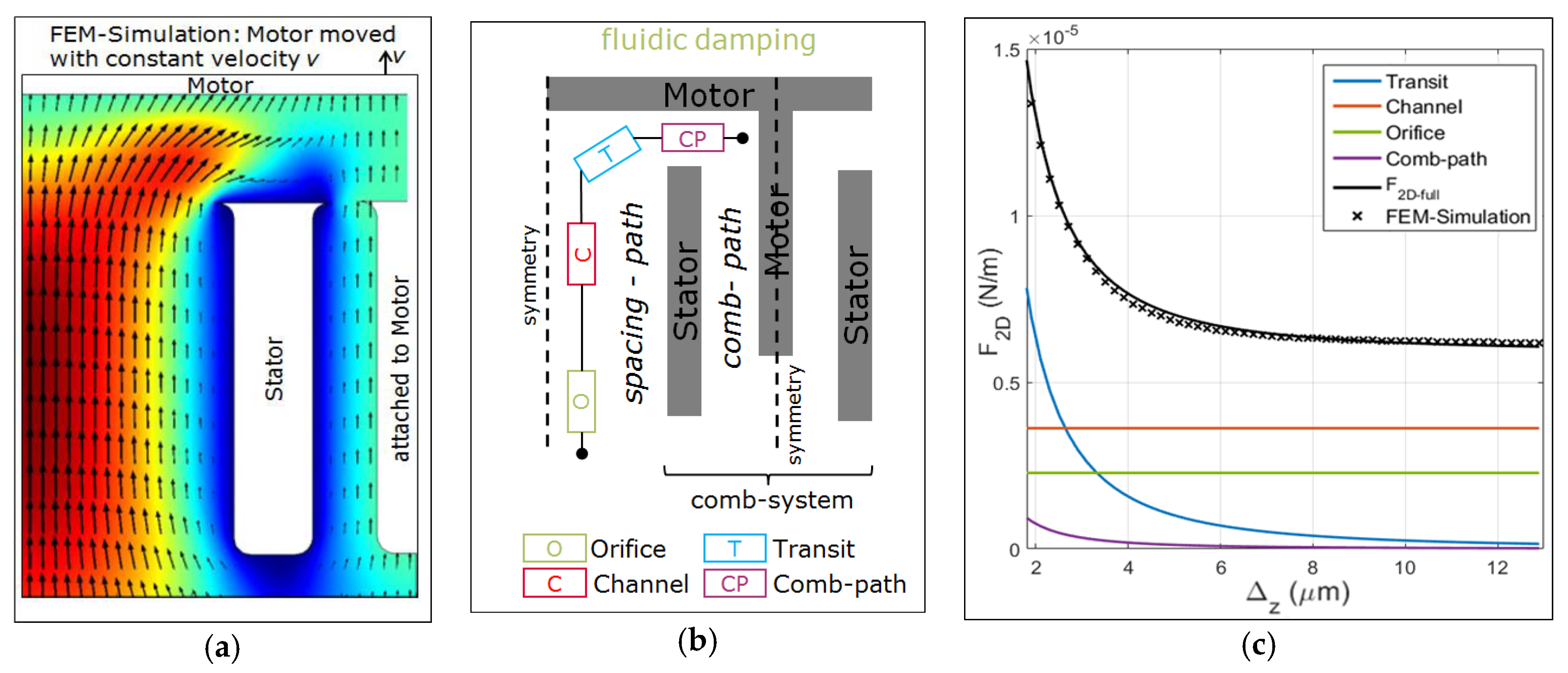
Figure 4.
(a) Frequency response of the microphone: comparison with LDV measurements for different bias voltages (b) Spectral noise density of a device with 50% overlap of the combs.
Figure 4.
(a) Frequency response of the microphone: comparison with LDV measurements for different bias voltages (b) Spectral noise density of a device with 50% overlap of the combs.


Table 1.
Simulated and measured Q-factors and displacements for different design variants (N: number of comb-systems, L: radial width of comb-fingers).
Table 1.
Simulated and measured Q-factors and displacements for different design variants (N: number of comb-systems, L: radial width of comb-fingers).
| Parameter | Q-Factor (sim.) | Q-Factor (meas.) | Amplitude at 1 kHz (sim.) | Amplitude at 1 kHz (meas.) |
|---|---|---|---|---|
| N = 60, L = 150 μm | 10.0 | ± 0.04 | 40.8 nm | ± 0.3 nm |
| N = 30, L = 150 μm | 14.6 | ± 0.50 | 26.1 nm | ± 4.5 nm |
| N = 90, L = 200 μm | 7.69 | ± 0.08 | 58.9 nm | ± 0.2 nm |
Publisher’s Note: MDPI stays neutral with regard to jurisdictional claims in published maps and institutional affiliations. |
© 2017 by the authors. Licensee MDPI, Basel, Switzerland. This article is an open access article distributed under the terms and conditions of the Creative Commons Attribution (CC BY) license (https://creativecommons.org/licenses/by/4.0/).
Share and Cite
MDPI and ACS Style
Anzinger, S.; Manz, J.; Dehe, A.; Schrag, G. A Comb-Based Capacitive MEMS Microphone with High Signal-to-Noise Ratio: Modeling and Noise-Level Analysis. Proceedings 2017, 1, 346. https://doi.org/10.3390/proceedings1040346
AMA Style
Anzinger S, Manz J, Dehe A, Schrag G. A Comb-Based Capacitive MEMS Microphone with High Signal-to-Noise Ratio: Modeling and Noise-Level Analysis. Proceedings. 2017; 1(4):346. https://doi.org/10.3390/proceedings1040346
Chicago/Turabian StyleAnzinger, Sebastian, Johannes Manz, Alfons Dehe, and Gabriele Schrag. 2017. "A Comb-Based Capacitive MEMS Microphone with High Signal-to-Noise Ratio: Modeling and Noise-Level Analysis" Proceedings 1, no. 4: 346. https://doi.org/10.3390/proceedings1040346